EP1385710B1 - Dispositif de fixation d'un module electronique de surveillance sur un pneumatique - Google Patents
Dispositif de fixation d'un module electronique de surveillance sur un pneumatique Download PDFInfo
- Publication number
- EP1385710B1 EP1385710B1 EP02727536A EP02727536A EP1385710B1 EP 1385710 B1 EP1385710 B1 EP 1385710B1 EP 02727536 A EP02727536 A EP 02727536A EP 02727536 A EP02727536 A EP 02727536A EP 1385710 B1 EP1385710 B1 EP 1385710B1
- Authority
- EP
- European Patent Office
- Prior art keywords
- patch
- insert
- electronic monitoring
- plaster
- tyre
- Prior art date
- Legal status (The legal status is an assumption and is not a legal conclusion. Google has not performed a legal analysis and makes no representation as to the accuracy of the status listed.)
- Expired - Lifetime
Links
Images

Classifications
-
- B—PERFORMING OPERATIONS; TRANSPORTING
- B60—VEHICLES IN GENERAL
- B60C—VEHICLE TYRES; TYRE INFLATION; TYRE CHANGING; CONNECTING VALVES TO INFLATABLE ELASTIC BODIES IN GENERAL; DEVICES OR ARRANGEMENTS RELATED TO TYRES
- B60C23/00—Devices for measuring, signalling, controlling, or distributing tyre pressure or temperature, specially adapted for mounting on vehicles; Arrangement of tyre inflating devices on vehicles, e.g. of pumps or of tanks; Tyre cooling arrangements
- B60C23/02—Signalling devices actuated by tyre pressure
- B60C23/04—Signalling devices actuated by tyre pressure mounted on the wheel or tyre
- B60C23/0491—Constructional details of means for attaching the control device
- B60C23/0493—Constructional details of means for attaching the control device for attachment on the tyre
-
- B—PERFORMING OPERATIONS; TRANSPORTING
- B29—WORKING OF PLASTICS; WORKING OF SUBSTANCES IN A PLASTIC STATE IN GENERAL
- B29D—PRODUCING PARTICULAR ARTICLES FROM PLASTICS OR FROM SUBSTANCES IN A PLASTIC STATE
- B29D30/00—Producing pneumatic or solid tyres or parts thereof
- B29D30/0061—Accessories, details or auxiliary operations not otherwise provided for
- B29D2030/0072—Attaching fasteners to tyres, e.g. patches, in order to connect devices to tyres
-
- B—PERFORMING OPERATIONS; TRANSPORTING
- B29—WORKING OF PLASTICS; WORKING OF SUBSTANCES IN A PLASTIC STATE IN GENERAL
- B29D—PRODUCING PARTICULAR ARTICLES FROM PLASTICS OR FROM SUBSTANCES IN A PLASTIC STATE
- B29D30/00—Producing pneumatic or solid tyres or parts thereof
- B29D30/0061—Accessories, details or auxiliary operations not otherwise provided for
- B29D2030/0077—Directly attaching monitoring devices to tyres before or after vulcanization, e.g. microchips
-
- Y—GENERAL TAGGING OF NEW TECHNOLOGICAL DEVELOPMENTS; GENERAL TAGGING OF CROSS-SECTIONAL TECHNOLOGIES SPANNING OVER SEVERAL SECTIONS OF THE IPC; TECHNICAL SUBJECTS COVERED BY FORMER USPC CROSS-REFERENCE ART COLLECTIONS [XRACs] AND DIGESTS
- Y10—TECHNICAL SUBJECTS COVERED BY FORMER USPC
- Y10T—TECHNICAL SUBJECTS COVERED BY FORMER US CLASSIFICATION
- Y10T152/00—Resilient tires and wheels
- Y10T152/10—Tires, resilient
Definitions
- the invention relates to tires equipped with electronic modules of removable monitoring and securing device such modules on the pneumatic, modules generally encapsulated in rigid housings.
- EP-0 936 089 discloses such solutions in which modules including both circuits and reloading batteries are inserted in rubber plasters comparable to those used for make repairs and carry a circular housing allowing the in place of the module, these plasters are fixed under the crown of the tire by a self-vulcanizing system.
- Different systems for fixing the module in the housing are presented such as a module with a locking ring or with a thread to realize its screwing.
- This zone is indeed more subject to deformations which risk adversely affect the good performance of the interface between the plaster and the tire. This phenomenon is further accentuated by the large size of the surface of the plaster carrying the module that will generate a large area of work on the tire. It should be noted, moreover, that the presented embodiment does not allow to use a more conventional system of repair with a rubber eraser with a hot glue that improves this interface hold.
- the subject of the invention is tires and fastening devices removable electronic surveillance modules likely to contain batteries overcoming all the aforementioned drawbacks.
- the device for fixing an electronic module of monitoring on a tire includes the features of claim 1.
- the invention also relates to a tire thus equipped.
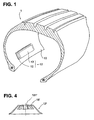
- the tire 1 carries at its internal lining An electronic monitoring module carried by a fixing device 11.
- This fixing device comprises a repair patch 12 fixed on the pneumatic and a housing 13 carrying the electronic module and fixed on the plaster 12.
- the housing 13 carries two brackets 131 and 132 on the plaster 12 by means of two screws 14 and 15 to come to screw in the plaster 12, washers 16 and 17 cooperating with said screws for the maintaining the housing 13 in position relative to the plaster 12.
- the plaster 12 will be described more precisely with reference to FIG. 12 carries two housings 121 and 122 for receiving inserts 18 and 19 of form frustoconical which carries in their center a thread 181 and 191 intended to cooperate with the screws 14 and 15.
- the bond between the patch 12 made in mixture elastomer and inserts is achieved by gluing, however the form frustoconical inserts helps prevent them from becoming to separate from the plaster under certain constraints.
- the contour of the plaster follows the frustoconical shapes of the inserts 18 and 19, which allows the plaster by the particular form it adopts to act vis-à-vis the housing 13 as a silent-block damping stresses and deformations suffered by the tire and therefore by the plaster, this provision allows in particular to position the fixing device 11 in the lower zone of the pneumatic as shown in Figure 1 but also in any what other interior position of the tire.
- the outer surface 130 of the plaster which will be free once the plaster installed in the tire is covered with a butyl rubber coating for maintain its tightness vis-à-vis including gases and oxidation.
- the whole of the plaster 12 can be made entirely of rubber butyl or be formed in the heart of the plaster by other mixtures elastomeric.
- the surface 182, 192 respectively bases of smaller diameter inserts 18, 19 is not in contact with the air but in contact with the butyl rubber layer.
- this insert is chosen to present both good adhesion with rubber and good rigidity so these inserts can be made in "NYLON” (registered trademark), bronze or brass.
- the choice of metal in the case of a metal insert is, in fact, limited so as not to generate a field magnetic that may interfere with the module.
- the plaster 12 is in contact with a polyester fabric 21 which will be removed during its use, as for the more traditional plasters of repair, with a rubber compound to be fixed on the tire.
- a self-vulcanizing adhesive for bonding with the pneumatic it may be interesting to keep the system hot with the bonding rubber which improves the performance of the plaster-pneumatic interface.
- the plaster can be made by hot molding on the inserts in a mold in the case where we choose a single rubber mix to achieve it. We can also produce a stack of cold products in a mold and cook.
- FIG. 4 represents an embodiment variant of the plaster 12 'which possesses a single insert 18 'carrying the thread 181'.
- This plaster with a single insert can suffice especially if we consider a module without batteries so lower clutter and weight.
- the fixing screw of the housing with the plaster can in such a case be directly attached to the housing.
Landscapes
- Engineering & Computer Science (AREA)
- Mechanical Engineering (AREA)
- Tires In General (AREA)
- Measuring Fluid Pressure (AREA)
- Arrangements For Transmission Of Measured Signals (AREA)
- Fittings On The Vehicle Exterior For Carrying Loads, And Devices For Holding Or Mounting Articles (AREA)
- Force Measurement Appropriate To Specific Purposes (AREA)
Description
- la figure 1 est une représentation schématique d'un pneumatique sur lequel est fixé intérieurement un module de surveillance électronique conformément à l'invention,
- la figure 2 est une représentation en coupe du dispositif de fixation du module représenté sur la figure 1,
- la figure 3 est une représentation en coupe de l'emplâtre utilisé dans le dispositif de fixation représenté sur la figure 2,
- la figure 4 est une représentation en coupe de l'emplâtre représenté sur la figure 3 selon une variante de réalisation.
Claims (12)
- Dispositif de fixation d'un module électronique de surveillance sur un pneumatique, ledit dispositif de fixation (11) comprenant un emplâtre (12) en mélange caoutchouteux dont la surface destinée à être au contact de l'air porte au moins un insert rigide (18,19) comportant un filetage (181,191) destiné à coopérer avec une vis (14,15), caractérisé en ce qu'une patte de fixation (131,132) portée par un boítier (13) portant le module de surveillance électronique coopère avec ladite vis (14,15) pour le maintien en position du boítier (13) par rapport à l'emplâtre (12).
- Dispositif selon la revendication 1, dans lequel l'insert (18, 19) a une forme tronconique de sorte que sa base de plus faible diamètre soit disposée à l'opposé de la surface de contact de l'insert avec le pneumatique.
- Dispositif selon la revendication 2, dans lequel la forme extérieure de l'emplâtre (12) suit celle de l'insert (18, 19).
- Dispositif selon l'une quelconque des revendications 1 à 3, dans lequel l'insert (18, 19) est réalisé en bronze.
- Dispositif selon l'une quelconque des revendications 1 à 3, dans lequel l'insert (18, 19) est réalisé en « NYLON ».
- Dispositif selon l'une quelconque des revendications 1 à 3, dans lequel l'insert (18, 19) est réalisé en laiton.
- Dispositif selon l'une quelconque des revendications 1 à 6, dans lequel l'emplâtre (12) porte deux inserts (18, 19), la forme extérieure de l'emplâtre (12) suivant celles des deux inserts de sorte que l'emplâtre constitue un silent-bloc vis-à-vis du boítier (12).
- Dispositif selon l'une quelconque des revendications 1 à 7, dans lequel l'emplâtre (12) comporte un tissu de rigidification (20).
- Dispositif selon la revendication 8, dans lequel le tissu de rigidification (20) est constitué par de la rayonne.
- Dispositif selon l'une quelconque des revendications 1 à 9, dans lequel la surface (130) de l'emplâtre (12) destiné à être au contact de l'air est recouverte d'un revêtement imperméable aux gaz.
- Dispositif selon la revendication 10, dans lequel le revêtement imperméable aux gaz est constitué par un caoutchouc butyle.
- Pneumatique comportant un dispositif de fixation d'un module électronique de surveillance selon l'une quelconque des revendications 1 à 11.
Applications Claiming Priority (3)
| Application Number | Priority Date | Filing Date | Title |
|---|---|---|---|
| FR0105071A FR2823148A1 (fr) | 2001-04-09 | 2001-04-09 | Dispositif de fixation d'un module electronique de surveillance sur un pneumatique |
| FR0105071 | 2001-04-09 | ||
| PCT/EP2002/003840 WO2002081238A1 (fr) | 2001-04-09 | 2002-04-08 | Dispositif de fixation d'un module electronique de surveillance sur un pneumatique |
Publications (2)
| Publication Number | Publication Date |
|---|---|
| EP1385710A1 EP1385710A1 (fr) | 2004-02-04 |
| EP1385710B1 true EP1385710B1 (fr) | 2005-06-29 |
Family
ID=8862310
Family Applications (1)
| Application Number | Title | Priority Date | Filing Date |
|---|---|---|---|
| EP02727536A Expired - Lifetime EP1385710B1 (fr) | 2001-04-09 | 2002-04-08 | Dispositif de fixation d'un module electronique de surveillance sur un pneumatique |
Country Status (10)
| Country | Link |
|---|---|
| US (1) | US6782741B2 (fr) |
| EP (1) | EP1385710B1 (fr) |
| JP (1) | JP4009201B2 (fr) |
| AT (1) | ATE298675T1 (fr) |
| BR (1) | BRPI0208720B1 (fr) |
| CA (1) | CA2442294A1 (fr) |
| DE (1) | DE60204871T2 (fr) |
| FR (1) | FR2823148A1 (fr) |
| WO (1) | WO2002081238A1 (fr) |
| ZA (1) | ZA200307404B (fr) |
Families Citing this family (28)
| Publication number | Priority date | Publication date | Assignee | Title |
|---|---|---|---|---|
| DE10131411A1 (de) * | 2001-06-26 | 2003-02-20 | Beru Ag | Rad für Fahrzeuge mit Luftreifen und Anordnung aus einem Ventil, einer Vorrichtung zum Messen des Reifendruckes und einer sie im Luftreifen haltenden Feder |
| US6952160B1 (en) * | 2002-08-07 | 2005-10-04 | Ford Global Technologies, Llc | Method and apparatus, for identifying the location of pressure sensors in a tire pressure monitoring system |
| DE10255138A1 (de) * | 2002-11-26 | 2004-06-17 | Iq-Mobil Electronics Gmbh | Haltevorrichtung zur Befestigung eines elektronischen Bauteils |
| JP4255301B2 (ja) * | 2003-03-31 | 2009-04-15 | 横浜ゴム株式会社 | タイヤ用電子部品の取り付け構造 |
| US7106688B2 (en) * | 2003-04-14 | 2006-09-12 | Cisco Technology, Inc. | System and method for preventing phantom data communication links |
| FR2861650B1 (fr) * | 2003-11-05 | 2006-01-06 | Michelin Soc Tech | Dispositif de fixation d'un module de surveillance sur la surface interieure d'un pneumatique |
| US20060237109A1 (en) * | 2003-11-17 | 2006-10-26 | Anton Mangold | Holding device for fixing an electronic component |
| US20050262934A1 (en) * | 2004-05-25 | 2005-12-01 | Sensfab Pte Ltd | Tyre pressure monitoring sensor |
| US7224269B2 (en) * | 2004-12-15 | 2007-05-29 | Ford Global Technologies, Llc | Method and system for resetting tire pressure monitoring system for an automotive vehicle |
| US7441452B2 (en) * | 2005-05-09 | 2008-10-28 | Ford Global Technologies, Llc | TPMS sensor assembly and method therefore |
| US7369043B2 (en) * | 2005-05-11 | 2008-05-06 | Ford Global Technologies, Llc | Method and apparatus for automatically identifying the location of pressure sensors in a tire pressure monitoring system |
| US7954370B2 (en) * | 2005-06-10 | 2011-06-07 | Michelin Recherche Et Technique | Use of piezoelectric sensor attached to electronics package housing |
| US7570157B2 (en) * | 2005-10-24 | 2009-08-04 | Ford Global Technologies, Llc | Method and apparatus for adjusting the pressure sensor measurement range in a tire pressure monitoring system |
| WO2007049093A1 (fr) * | 2005-10-28 | 2007-05-03 | Pirelli Tyre S.P.A. | Pneu comprenant une unite electronique, et procede permettant de monter l'unite electronique dans le pneu |
| US7705717B2 (en) * | 2005-11-30 | 2010-04-27 | Ford Global Technologies | Method and apparatus for receiving signals from a sensor into a tire pressure monitoring system |
| FR2902173B1 (fr) * | 2006-06-09 | 2008-12-05 | Michelin Soc Tech | Valve de pneumatique et procede pour son demontage |
| FR2903752B1 (fr) * | 2006-07-13 | 2008-12-05 | Michelin Soc Tech | Valve de pneumatique. |
| EP2318222B1 (fr) * | 2008-08-29 | 2016-06-22 | Compagnie Générale des Etablissements Michelin | Appareil à pneumatique 1-d |
| FR2940930B1 (fr) | 2009-01-09 | 2011-11-18 | Michelin Soc Tech | Ensemble de fixation d'un module electronique a une paroi interne d'un pneumatique |
| CN102371859B (zh) * | 2010-08-19 | 2014-02-12 | 青岛泰凯英轮胎有限公司 | 轮胎胎压监测系统安装底座及装置 |
| US20120112898A1 (en) * | 2010-11-05 | 2012-05-10 | San-Chuan Yu | Programmable tire-condition sensor having a flexible shell, its installation method and a tire carrying same |
| WO2012110877A1 (fr) | 2011-02-16 | 2012-08-23 | 1814393 Ontario Inc. | Système de montage pour détection de pression de pneumatique |
| US20140130357A1 (en) | 2012-11-09 | 2014-05-15 | The Goodyear Tire & Rubber Company | Securing to a pneumatic tire |
| US20140174621A1 (en) * | 2012-12-20 | 2014-06-26 | The Goodyear Tire & Rubber Company | Pneumatic tire with built in fastener system |
| FR3029845B1 (fr) * | 2014-12-15 | 2017-08-11 | Michelin & Cie | Patch pour module electronique de pneumatique |
| JP2017071341A (ja) * | 2015-10-08 | 2017-04-13 | 株式会社デンソー | タイヤマウントセンサおよびそれに用いられるセンサ装置 |
| FR3059603A1 (fr) * | 2016-12-07 | 2018-06-08 | Compagnie Generale Des Etablissements Michelin | Pneumatique adapte pour roulage a plat equipe d’un organe electronique |
| CN110406143A (zh) * | 2019-08-27 | 2019-11-05 | 杭州朝阳橡胶有限公司 | 一种在轮胎内部自动贴合tpms传感器的系统 |
Family Cites Families (9)
| Publication number | Priority date | Publication date | Assignee | Title |
|---|---|---|---|---|
| US4862486A (en) | 1987-11-16 | 1989-08-29 | Wing J Keith | Revolution counter attached to tires |
| US5218861A (en) | 1991-03-27 | 1993-06-15 | The Goodyear Tire & Rubber Company | Pneumatic tire having an integrated circuit transponder and pressure transducer |
| US5500065A (en) | 1994-06-03 | 1996-03-19 | Bridgestone/Firestone, Inc. | Method for embedding a monitoring device within a tire during manufacture |
| US6030478A (en) | 1998-02-10 | 2000-02-29 | Bridgestone/Firestone, Inc. | Method and apparatus for removably inserting an electric tire tag into a tire |
| WO1999041093A1 (fr) * | 1998-02-12 | 1999-08-19 | Michelin Recherche Et Technique S.A. | Dispositif de fixation de module electronique de pneu |
| US6192746B1 (en) * | 1999-04-29 | 2001-02-27 | Bridgestone/Firestone Research, Inc. | Apparatus and method of providing electrical power to an active electronic device embedded within a tire |
| US6255940B1 (en) * | 1999-10-01 | 2001-07-03 | The Goodyear Tire & Rubber Company | Apparatus for monitoring a condition of a tire |
| US6462650B1 (en) * | 2000-08-11 | 2002-10-08 | Raymond J. Balzer | Tire module attachment mount |
| US6688353B1 (en) * | 2000-03-31 | 2004-02-10 | Bridgestone/Firestone North American Tire, Llc | Attachment patch for mounting an electronic monitoring device to the inside of a pneumatic tire |
-
2001
- 2001-04-09 FR FR0105071A patent/FR2823148A1/fr active Pending
-
2002
- 2002-04-08 BR BRPI0208720A patent/BRPI0208720B1/pt not_active IP Right Cessation
- 2002-04-08 EP EP02727536A patent/EP1385710B1/fr not_active Expired - Lifetime
- 2002-04-08 CA CA002442294A patent/CA2442294A1/fr not_active Abandoned
- 2002-04-08 WO PCT/EP2002/003840 patent/WO2002081238A1/fr active IP Right Grant
- 2002-04-08 DE DE60204871T patent/DE60204871T2/de not_active Expired - Lifetime
- 2002-04-08 JP JP2002579250A patent/JP4009201B2/ja not_active Expired - Fee Related
- 2002-04-08 AT AT02727536T patent/ATE298675T1/de not_active IP Right Cessation
-
2003
- 2003-09-23 ZA ZA200307404A patent/ZA200307404B/xx unknown
- 2003-10-03 US US10/678,835 patent/US6782741B2/en not_active Expired - Lifetime
Also Published As
| Publication number | Publication date |
|---|---|
| US20040112489A1 (en) | 2004-06-17 |
| US6782741B2 (en) | 2004-08-31 |
| ATE298675T1 (de) | 2005-07-15 |
| BR0208720A (pt) | 2004-07-20 |
| FR2823148A1 (fr) | 2002-10-11 |
| ZA200307404B (en) | 2004-04-21 |
| DE60204871D1 (de) | 2005-08-04 |
| JP4009201B2 (ja) | 2007-11-14 |
| CA2442294A1 (fr) | 2002-10-17 |
| DE60204871T2 (de) | 2006-05-18 |
| WO2002081238A1 (fr) | 2002-10-17 |
| EP1385710A1 (fr) | 2004-02-04 |
| BRPI0208720B1 (pt) | 2016-12-27 |
| JP2004523425A (ja) | 2004-08-05 |
Similar Documents
| Publication | Publication Date | Title |
|---|---|---|
| EP1385710B1 (fr) | Dispositif de fixation d'un module electronique de surveillance sur un pneumatique | |
| EP1684997B1 (fr) | Dispositif de fixation d'un module sur la surface d'un pneumatique | |
| US10105999B2 (en) | System and method for tire rims configured to receive gravity-based devices | |
| US6832573B2 (en) | Wheel-mounted tire pressure gauge | |
| US20020059972A1 (en) | Wheel with integral compressed air tank apparatus | |
| FR2897014A1 (fr) | Dispositif de securite pour roue de vehicule | |
| US20020139288A1 (en) | Wheel-mounted tire pressure gauge | |
| US7275427B1 (en) | Device for mounting electronic monitoring components to a tire | |
| EP3328710B1 (fr) | Joint de tablier pour l'accouplement d'un dispositif de direction assistée au tablier d'un véhicule | |
| JPH08511323A (ja) | ライナ/外部機構直結式の流体圧力容器のボス−ライナ取付装置 | |
| US20080006358A1 (en) | Wheel rim, in particular for an all-terrain vehicle or running at low pressure | |
| JP2005280514A (ja) | 懸架装置 | |
| JP3979710B2 (ja) | 安全弁 | |
| US10682598B2 (en) | Device for storing a fuel filter in a vehicle and method | |
| US7591360B2 (en) | Clutch assembly | |
| ES2105629T3 (es) | Disposicion de conjunto para mediciones del par de giro en vehiculos de motor. | |
| CN220663467U (zh) | 一种内封式双物料桶装水盖及桶装水桶 | |
| US20080086862A1 (en) | Repair for crankshaft ends | |
| CN220102829U (zh) | 一种精密耐候汽车塑胶配件 | |
| JP2521067B2 (ja) | 自動車の応急用タイヤ | |
| CN220615390U (zh) | 一种车轮总成及车辆 | |
| US4258772A (en) | Air valve tightening construction for tire tube | |
| FR3071567A1 (fr) | Dispositif de fixation antivibratoire | |
| US20220324257A1 (en) | Assembly for an inner tube | |
| CN112644272A (zh) | 一种后轮分离器 |
Legal Events
| Date | Code | Title | Description |
|---|---|---|---|
| PUAI | Public reference made under article 153(3) epc to a published international application that has entered the european phase |
Free format text: ORIGINAL CODE: 0009012 |
|
| 17P | Request for examination filed |
Effective date: 20031110 |
|
| AK | Designated contracting states |
Kind code of ref document: A1 Designated state(s): AT BE CH CY DE DK ES FI FR GB GR IE IT LI LU MC NL PT SE TR |
|
| AX | Request for extension of the european patent |
Extension state: AL LT LV MK RO SI |
|
| GRAP | Despatch of communication of intention to grant a patent |
Free format text: ORIGINAL CODE: EPIDOSNIGR1 |
|
| GRAS | Grant fee paid |
Free format text: ORIGINAL CODE: EPIDOSNIGR3 |
|
| GRAA | (expected) grant |
Free format text: ORIGINAL CODE: 0009210 |
|
| AK | Designated contracting states |
Kind code of ref document: B1 Designated state(s): AT BE CH CY DE DK ES FI FR GB GR IE IT LI LU MC NL PT SE TR |
|
| PG25 | Lapsed in a contracting state [announced via postgrant information from national office to epo] |
Ref country code: NL Free format text: LAPSE BECAUSE OF FAILURE TO SUBMIT A TRANSLATION OF THE DESCRIPTION OR TO PAY THE FEE WITHIN THE PRESCRIBED TIME-LIMIT Effective date: 20050629 Ref country code: TR Free format text: LAPSE BECAUSE OF FAILURE TO SUBMIT A TRANSLATION OF THE DESCRIPTION OR TO PAY THE FEE WITHIN THE PRESCRIBED TIME-LIMIT Effective date: 20050629 Ref country code: FI Free format text: LAPSE BECAUSE OF FAILURE TO SUBMIT A TRANSLATION OF THE DESCRIPTION OR TO PAY THE FEE WITHIN THE PRESCRIBED TIME-LIMIT Effective date: 20050629 Ref country code: IE Free format text: LAPSE BECAUSE OF FAILURE TO SUBMIT A TRANSLATION OF THE DESCRIPTION OR TO PAY THE FEE WITHIN THE PRESCRIBED TIME-LIMIT Effective date: 20050629 Ref country code: AT Free format text: LAPSE BECAUSE OF FAILURE TO SUBMIT A TRANSLATION OF THE DESCRIPTION OR TO PAY THE FEE WITHIN THE PRESCRIBED TIME-LIMIT Effective date: 20050629 Ref country code: IT Free format text: LAPSE BECAUSE OF FAILURE TO SUBMIT A TRANSLATION OF THE DESCRIPTION OR TO PAY THE FEE WITHIN THE PRESCRIBED TIME-LIMIT;WARNING: LAPSES OF ITALIAN PATENTS WITH EFFECTIVE DATE BEFORE 2007 MAY HAVE OCCURRED AT ANY TIME BEFORE 2007. THE CORRECT EFFECTIVE DATE MAY BE DIFFERENT FROM THE ONE RECORDED. Effective date: 20050629 |
|
| REG | Reference to a national code |
Ref country code: GB Ref legal event code: FG4D Free format text: NOT ENGLISH |
|
| REG | Reference to a national code |
Ref country code: CH Ref legal event code: EP |
|
| REF | Corresponds to: |
Ref document number: 60204871 Country of ref document: DE Date of ref document: 20050804 Kind code of ref document: P |
|
| REG | Reference to a national code |
Ref country code: IE Ref legal event code: FG4D Free format text: LANGUAGE OF EP DOCUMENT: FRENCH |
|
| PG25 | Lapsed in a contracting state [announced via postgrant information from national office to epo] |
Ref country code: GR Free format text: LAPSE BECAUSE OF FAILURE TO SUBMIT A TRANSLATION OF THE DESCRIPTION OR TO PAY THE FEE WITHIN THE PRESCRIBED TIME-LIMIT Effective date: 20050929 Ref country code: DK Free format text: LAPSE BECAUSE OF FAILURE TO SUBMIT A TRANSLATION OF THE DESCRIPTION OR TO PAY THE FEE WITHIN THE PRESCRIBED TIME-LIMIT Effective date: 20050929 Ref country code: SE Free format text: LAPSE BECAUSE OF FAILURE TO SUBMIT A TRANSLATION OF THE DESCRIPTION OR TO PAY THE FEE WITHIN THE PRESCRIBED TIME-LIMIT Effective date: 20050929 |
|
| GBT | Gb: translation of ep patent filed (gb section 77(6)(a)/1977) |
Effective date: 20050930 |
|
| NLV1 | Nl: lapsed or annulled due to failure to fulfill the requirements of art. 29p and 29m of the patents act | ||
| PG25 | Lapsed in a contracting state [announced via postgrant information from national office to epo] |
Ref country code: PT Free format text: LAPSE BECAUSE OF FAILURE TO SUBMIT A TRANSLATION OF THE DESCRIPTION OR TO PAY THE FEE WITHIN THE PRESCRIBED TIME-LIMIT Effective date: 20051207 |
|
| REG | Reference to a national code |
Ref country code: IE Ref legal event code: FD4D |
|
| PG25 | Lapsed in a contracting state [announced via postgrant information from national office to epo] |
Ref country code: LI Free format text: LAPSE BECAUSE OF NON-PAYMENT OF DUE FEES Effective date: 20060430 Ref country code: MC Free format text: LAPSE BECAUSE OF NON-PAYMENT OF DUE FEES Effective date: 20060430 Ref country code: CH Free format text: LAPSE BECAUSE OF NON-PAYMENT OF DUE FEES Effective date: 20060430 Ref country code: BE Free format text: LAPSE BECAUSE OF NON-PAYMENT OF DUE FEES Effective date: 20060430 |
|
| PLBE | No opposition filed within time limit |
Free format text: ORIGINAL CODE: 0009261 |
|
| STAA | Information on the status of an ep patent application or granted ep patent |
Free format text: STATUS: NO OPPOSITION FILED WITHIN TIME LIMIT |
|
| 26N | No opposition filed |
Effective date: 20060330 |
|
| REG | Reference to a national code |
Ref country code: CH Ref legal event code: PL |
|
| BERE | Be: lapsed |
Owner name: SOC. DE TECHNOLOGIE MICHELIN Effective date: 20060430 Owner name: MICHELIN RECHERCHE ET TECHNIQUE S.A. Effective date: 20060430 |
|
| PG25 | Lapsed in a contracting state [announced via postgrant information from national office to epo] |
Ref country code: LU Free format text: LAPSE BECAUSE OF NON-PAYMENT OF DUE FEES Effective date: 20060408 |
|
| PG25 | Lapsed in a contracting state [announced via postgrant information from national office to epo] |
Ref country code: CY Free format text: LAPSE BECAUSE OF FAILURE TO SUBMIT A TRANSLATION OF THE DESCRIPTION OR TO PAY THE FEE WITHIN THE PRESCRIBED TIME-LIMIT Effective date: 20050629 |
|
| PG25 | Lapsed in a contracting state [announced via postgrant information from national office to epo] |
Ref country code: ES Free format text: LAPSE BECAUSE OF NON-PAYMENT OF DUE FEES Effective date: 20060430 |
|
| REG | Reference to a national code |
Ref country code: FR Ref legal event code: PLFP Year of fee payment: 15 |
|
| PGFP | Annual fee paid to national office [announced via postgrant information from national office to epo] |
Ref country code: GB Payment date: 20160421 Year of fee payment: 15 |
|
| PGFP | Annual fee paid to national office [announced via postgrant information from national office to epo] |
Ref country code: FR Payment date: 20160421 Year of fee payment: 15 |
|
| GBPC | Gb: european patent ceased through non-payment of renewal fee |
Effective date: 20170408 |
|
| REG | Reference to a national code |
Ref country code: FR Ref legal event code: ST Effective date: 20171229 |
|
| PG25 | Lapsed in a contracting state [announced via postgrant information from national office to epo] |
Ref country code: FR Free format text: LAPSE BECAUSE OF NON-PAYMENT OF DUE FEES Effective date: 20170502 |
|
| PG25 | Lapsed in a contracting state [announced via postgrant information from national office to epo] |
Ref country code: GB Free format text: LAPSE BECAUSE OF NON-PAYMENT OF DUE FEES Effective date: 20170408 |
|
| PGFP | Annual fee paid to national office [announced via postgrant information from national office to epo] |
Ref country code: DE Payment date: 20180420 Year of fee payment: 17 |
|
| REG | Reference to a national code |
Ref country code: DE Ref legal event code: R119 Ref document number: 60204871 Country of ref document: DE |
|
| PG25 | Lapsed in a contracting state [announced via postgrant information from national office to epo] |
Ref country code: DE Free format text: LAPSE BECAUSE OF NON-PAYMENT OF DUE FEES Effective date: 20191101 |