EP1385342B1 - Communication system and server - Google Patents
Communication system and server Download PDFInfo
- Publication number
- EP1385342B1 EP1385342B1 EP02016500A EP02016500A EP1385342B1 EP 1385342 B1 EP1385342 B1 EP 1385342B1 EP 02016500 A EP02016500 A EP 02016500A EP 02016500 A EP02016500 A EP 02016500A EP 1385342 B1 EP1385342 B1 EP 1385342B1
- Authority
- EP
- European Patent Office
- Prior art keywords
- server
- interface
- unit
- communication system
- connection
- Prior art date
- Legal status (The legal status is an assumption and is not a legal conclusion. Google has not performed a legal analysis and makes no representation as to the accuracy of the status listed.)
- Expired - Fee Related
Links
Images

Classifications
-
- H—ELECTRICITY
- H04—ELECTRIC COMMUNICATION TECHNIQUE
- H04M—TELEPHONIC COMMUNICATION
- H04M3/00—Automatic or semi-automatic exchanges
- H04M3/42—Systems providing special services or facilities to subscribers
- H04M3/42314—Systems providing special services or facilities to subscribers in private branch exchanges
- H04M3/42323—PBX's with CTI arrangements
-
- H—ELECTRICITY
- H04—ELECTRIC COMMUNICATION TECHNIQUE
- H04Q—SELECTING
- H04Q3/00—Selecting arrangements
- H04Q3/58—Arrangements providing connection between main exchange and sub-exchange or satellite
- H04Q3/62—Arrangements providing connection between main exchange and sub-exchange or satellite for connecting to private branch exchanges
-
- H—ELECTRICITY
- H04—ELECTRIC COMMUNICATION TECHNIQUE
- H04M—TELEPHONIC COMMUNICATION
- H04M7/00—Arrangements for interconnection between switching centres
- H04M7/0024—Services and arrangements where telephone services are combined with data services
-
- H—ELECTRICITY
- H04—ELECTRIC COMMUNICATION TECHNIQUE
- H04Q—SELECTING
- H04Q2213/00—Indexing scheme relating to selecting arrangements in general and for multiplex systems
- H04Q2213/13034—A/D conversion, code compression/expansion
-
- H—ELECTRICITY
- H04—ELECTRIC COMMUNICATION TECHNIQUE
- H04Q—SELECTING
- H04Q2213/00—Indexing scheme relating to selecting arrangements in general and for multiplex systems
- H04Q2213/13093—Personal computer, PC
-
- H—ELECTRICITY
- H04—ELECTRIC COMMUNICATION TECHNIQUE
- H04Q—SELECTING
- H04Q2213/00—Indexing scheme relating to selecting arrangements in general and for multiplex systems
- H04Q2213/13103—Memory
-
- H—ELECTRICITY
- H04—ELECTRIC COMMUNICATION TECHNIQUE
- H04Q—SELECTING
- H04Q2213/00—Indexing scheme relating to selecting arrangements in general and for multiplex systems
- H04Q2213/13104—Central control, computer control
-
- H—ELECTRICITY
- H04—ELECTRIC COMMUNICATION TECHNIQUE
- H04Q—SELECTING
- H04Q2213/00—Indexing scheme relating to selecting arrangements in general and for multiplex systems
- H04Q2213/13166—Fault prevention
-
- H—ELECTRICITY
- H04—ELECTRIC COMMUNICATION TECHNIQUE
- H04Q—SELECTING
- H04Q2213/00—Indexing scheme relating to selecting arrangements in general and for multiplex systems
- H04Q2213/13196—Connection circuit/link/trunk/junction, bridge, router, gateway
-
- H—ELECTRICITY
- H04—ELECTRIC COMMUNICATION TECHNIQUE
- H04Q—SELECTING
- H04Q2213/00—Indexing scheme relating to selecting arrangements in general and for multiplex systems
- H04Q2213/13209—ISDN
-
- H—ELECTRICITY
- H04—ELECTRIC COMMUNICATION TECHNIQUE
- H04Q—SELECTING
- H04Q2213/00—Indexing scheme relating to selecting arrangements in general and for multiplex systems
- H04Q2213/1322—PBX
-
- H—ELECTRICITY
- H04—ELECTRIC COMMUNICATION TECHNIQUE
- H04Q—SELECTING
- H04Q2213/00—Indexing scheme relating to selecting arrangements in general and for multiplex systems
- H04Q2213/13296—Packet switching, X.25, frame relay
-
- H—ELECTRICITY
- H04—ELECTRIC COMMUNICATION TECHNIQUE
- H04Q—SELECTING
- H04Q2213/00—Indexing scheme relating to selecting arrangements in general and for multiplex systems
- H04Q2213/13299—Bus
-
- H—ELECTRICITY
- H04—ELECTRIC COMMUNICATION TECHNIQUE
- H04Q—SELECTING
- H04Q2213/00—Indexing scheme relating to selecting arrangements in general and for multiplex systems
- H04Q2213/13389—LAN, internet
Definitions
- the communication system is subdivided into a central unit with a central control unit for controlling the communication system and a switching network for switching information to be transmitted as well as into a peripheral unit having a plurality of connection units.
- the connection units serve a connection of communication terminals or a communication network to the communication system.
- the central unit comprises is arranged on a central module of the communication system.
- the terminal units are each arranged on a separate peripheral module, which can be connected to the central module, for example via connectors.
- the present invention is therefore based on the object to provide a solution for a more reliable and efficient coupling of a server provided for specific operational tasks server to a communication system.
- An essential aspect of the present invention is that by a coupling of a server for a communication system to a communication system via a terminal unit the communication system can save a previously required for this purpose LAN module.
- protocol tunneling mechanisms for transmitting system messages are no longer needed to convert them, for example, for transmission according to a packet-oriented transmission protocol.
- FIG. 1 shows the structure of a communication system with a communication system 101 and a server 116 shown schematically.
- a communication system is described, for example, in WO 01/89231.
- the communication system 101 has a generally arranged on a central module central processing unit 102 to a central control device 103 (c ommon c ontrol -CC) and a switching network 104 (s witching n etwork - SN) on.
- the central control device 103 comprises a microprocessor 105 for controlling functions of the communication system 101.
- voice or data transmission channels to be connected via the communication system 101 are switched through.
- the central control device 103 and the switching network 104 are connected to one another via a conversion unit 106.
- the conversion unit 106 is a central for a microprocessor bus 107 between the controller 103 and the conversion unit 106 are used transmission protocol and a supported from the coupling network 104 HDLC protocol (h igh le vel d ata l ink c ontrol) bidirectionally converted into each other.
- IOM2 transmission protocol Details of the IOM2 transmission protocol can be found in the product brochure "ICs for Communications - IOM2 Interface Reference Guide", Siemens AG, Kunststoff 3/91, order no. B115-H6397-XX-7600, pages 6 to 12.
- IOM2-transmission protocol can be used for bidirectional data transmission between the switching network 104 and the terminal units 108, 109 110 and the PCM transmission protocol (p sleeve c ode m odulation) may be used.
- the communication system 101 For a connection of the communication system 101 to a data network, for example a local computer network 114 ( l ocal a rea n etwork -LAN), the communication system 101 has a separate data network coupling unit 115.
- the data network coupling unit 115 has a plurality of identical contact devices, not explicitly shown in FIG. 1, for connecting controller units.
- controller units have a HDLC and a PCM interface to the central unit 102 and a standard MII interface (m edium i ndependent i nterface) to a LAN terminal unit of the communication system 101.
- a connection between the local computer network 114 and the LAN Connection unit can be realized for example by means of a 10Base-T or a 100Base-T interface.
- a controller unit of the data network coupling unit 115 usually serves for protocol-based preprocessing of control data received via the local computer network 114 and its forwarding to the central unit 102.
- the central unit 102 then controls the execution of the functions identified by the control data.
- This also includes functions to be performed by the data network coupling unit 115.
- the functions such as coupling of different computer networks, external access to network resources in the context of "teleworking", CTI applications or "Voice over IP” applications are performed by the data network coupling unit 115 associated function-specific digital signal processors, which are controlled by the central control unit 103 ,
- To the local computer network 114 can be connected, for example, provided for specific tasks server 116, which make available for the communication system 101 on common personal computers but not in the central control unit 103 executable programs that do not need to be ported to the communication system 101.
- the central control unit 103 is relieved by outsourcing a corresponding program sequence control, so that process computing resources of the central control unit 103 can be reserved primarily for switching control tasks.
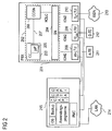
- FIG. 2 shows schematically the structure of a communication system with a communication system 201 and a server 215, which is connected to the communication system 201 via a connection unit 208, 209, 210 of the communication system 201.
- the communication system 201 shown in Figure 2 corresponds to the integration and functionality of the central unit 202, terminal units 208, 209, 210, communication terminals 211, 212 and other communication networks 213 of the communication system 101.
- the central unit 202 is divided into a central control unit 203 with a microprocessor 205, in a switching network 204 and in a conversion unit 206, which is connected via a microprocessor bus 207 to the central control unit.
- a server 215 is connected to the communication system 201 via one or more of the connection units 208, 209, 210.
- the server 215 has at least one central processing unit (not explicitly shown in FIG. 2) for executing application programs, an input / output unit and an interface for connection to a connection unit 208, 209, 210 of the communication system 201.
- On the server 215 is preferably a widespread operating system, such as MS-Windows, Unix or Linux, installed, so that the execution of a variety of common application programs is guaranteed.
- the interface of the server into one of the terminal units 208, 209, 210 may for example comprise a hardware-S0 interface and the software side a CAPI programming interface (c ommon a pplication p rogramming i nterface).
- a starting interface at the hardware level can be used a vCAPI Programming Interface (c ommon a pplication p rogramming i nterface) at the software level.
- two or more interfaces can be used in parallel.
- the server 215 has an interface for a data network with packet-oriented exchange, for example, a local computer network 214.
- the interface of the server 215 is made available for the communication system 201, so that an additional data network coupling unit 115 shown in FIG. 1 is no longer required is. This makes it possible to forward speech information to the server 215 for processing and to process it for use in the local computer network 214 allow.
- Possible fields of application are for example routing, remote access service (r emote a ccess s ervice - RAS), encryption, providing CAPI interfaces (c ommon a pplication p rogramming i nterface), file transfer, protocol conversion in accordance with the H.323 standard ( "Voice o -ver IP ”) or speech coding / compression.
- Other applications include providing a CSTA applications (c omputer s upported t elecommunications a pplication) on TAPI Programming Interfaces (t elephony a pplication p rogramming nterface) as well as a provision of TAPI drivers.
- a database backup program executable therein is installed in a storage unit of the server 215, which is made available to the communication equipment 201 for securing data for operating the communication equipment 201 and executing performance features, respectively.
- This offers the advantage of utilization in data processing of established and proven data protection mechanisms without the interposition of additional servers or without porting of the respective data backup programs to communication system operating systems.
- the server 215 has PMC module interfaces, which are also made available to the communication system 201.
- PMC module interfaces are preferably suitable for continuous, PC conventional peripheral cards and for example for applications such as ATM (a synchronous t ransfer m ode), xDSL (d igital s ubscriber L ine) signal encoding / -kompression, encryption, or "Voice -Mail "provided.
- the server 215 is preferably configured to perform system database / system software updates to the communication system through appropriate control programs. This offers the advantage that corresponding control programs do not have to be ported specifically to the operating system of the communication system 201. In addition, process computing resources of the central control unit 203 are thus reserved for call control tasks.
Description
Aus der Produktschrift "Sonderausgabe telcom report und Siemens Magazin COM: ISDN im Büro - HICOM", Siemens AG, Berlin und München, 1985, Seite 58 bis 75 ist eine Kommunikationsanlage für Informationsvermittlung bekannt, insbesondere Sprachinformationsvermittlung. Die Kommunikationsanlage ist in eine Zentraleinheit mit einer zentralen Steuerungseinheit zur Steuerung der Kommunikationsanlage und einem Koppelnetz zur Vermittlung von zu übertragenden Informationen sowie in eine mehrere Anschlußeinheiten aufweisende Peripherieeinheit untergliedert. Die Anschlußeinheiten dienen dabei einem Anschluß von Kommunikationsendgeräten oder eines Kommunikationsnetzes an die Kommunikationsanlage. Die Zentraleinheit umfaßt ist auf einer zentralen Baugruppe der Kommunikationsanlage angeordnet. Die Anschlußeinheiten sind jeweils auf einer separaten Peripherie-Baugruppe angeordnet, die mit der zentralen Baugruppe beispielsweise über Steckverbindungen verbindbar sind.From the product brochure "Special issue telcom report and Siemens Magazine COM: ISDN in the office - HICOM", Siemens AG, Berlin and Munich, 1985, pages 58 to 75, a communication system for information transfer is known, especially voice information. The communication system is subdivided into a central unit with a central control unit for controlling the communication system and a switching network for switching information to be transmitted as well as into a peripheral unit having a plurality of connection units. The connection units serve a connection of communication terminals or a communication network to the communication system. The central unit comprises is arranged on a central module of the communication system. The terminal units are each arranged on a separate peripheral module, which can be connected to the central module, for example via connectors.
Aus WO 01/89231 ist bekannt, für spezielle betriebliche Aufgaben vorgesehene Server über ein lokales Rechnernetz (lokal area network) eine LAN-Baugruppe mit einer Kommunikationsanlage zu verbinden, wobei die LAN-Baugruppe Bestandteil der Kommunikationsanlage ist. Aufgrund möglicher Störungen auf Übertragungsstrecken zwischen der Kommunikationsanlage und dem jeweiligen Server ist eine Auslagerung von Daten auf einen leistungsfähigen Rechner mit verhältnismäßig großen Speicherressourcen kritisch. Dies gilt insbesondere im Hinblick auf Datenverluste oder Netzwerkstörungen, welche die Erreichbarkeit von Ressourcen des jeweiligen Servers beeinträchtigen. Zudem ist für eine Übertragung von Systemmeldungen der Kommunikationsanlage zur Verarbeitung und Rückübermittlung durch einen externen Server eine Anwendung von Protokoll-Tunnelungsmechanismen im Hinblick auf unterschiedliche verwendete Übertragungsprotokolle erforderlich. Die Anwendung von Protokoll-Tunnelungsmechanismen wirkt sich dabei nachteilig auf bei der Übertragung zwischen Kommunikationsanlage und Server erreichte Datenübertragungsraten aus, insbesondere Nutzdatenübertragungsraten. Ein weiterer nachteiliger Aspekt sind bei einer Protokollumsetzung nie auszuschließende Daten- und Informationsverluste, die somit das Risiko von Datenübertragungsfehlern erhöhen.From WO 01/89231 it is known to provide for specific operational tasks server via a local computer network ( l okal a rea n etwork) to connect a LAN module with a communication system, the LAN module is part of the communication system. Due to possible disturbances on transmission links between the communication system and the respective server, a transfer of data to a powerful computer with relatively large storage resources is critical. This applies in particular with regard to data losses or network disruptions which impair the accessibility of resources of the respective server. In addition, for transmission of system messages of the communication equipment for processing and return by an external server, an application of protocol tunneling mechanisms with respect to different ones is used Transmission protocols required. The use of protocol tunneling mechanisms has a detrimental effect on data transmission rates achieved in the transmission between communication system and server, in particular user data transmission rates. Another disadvantageous aspect of a protocol implementation is never to be excluded data and information losses, thus increasing the risk of data transmission errors.
In US 6,052,461 ist ein Kommunikationssystem mit den Merkmalen entsprechend dem Oberbegriff des Anspruchs 1 beschrieben. Dagegen ist dort nicht offenbart, daß der Server zur Durchführung eines Systemsoftware-Updates für die Kommunikationsanlage ausgebildet ist. Statt dessen werden Status-Informationen bei Zustandsänderungen durch einen einer Nebenstellenanlage zugeordneten Server aktualisiert. Dies hat den Nachteil, daß Systemsoftware-Updates über zusätzliche Schnittstellen bereitgestellt werden müssen, was wiederum nachteilige Auswirkungen auf einen zuverlässigen und gegenüber unberechtigten Zugriffen sicheren Betrieb eines Kommunikationssystems hat.In US 6,052,461 a communication system having the features according to the preamble of claim 1 is described. In contrast, there is not disclosed that the server is designed to carry out a system software update for the communication system. Instead, status information on state changes is updated by a server associated with a PBX. This has the disadvantage that system software updates must be provided via additional interfaces, which in turn has detrimental effects on a reliable and unauthorized access operation of a communication system.
Der vorliegenden Erfindung liegt daher die Aufgabe zugrunde, eine Lösung für eine zuverlässigere und leistungsfähigere Kopplung eines für spezielle betriebliche Aufgaben vorgesehenen Servers an eine Kommunikationsanlage zu schaffen.The present invention is therefore based on the object to provide a solution for a more reliable and efficient coupling of a server provided for specific operational tasks server to a communication system.
Diese Aufgabe wird durch ein Kommunikationssystem mit den in Anspruch 1 angegebenen Merkmalen und einen Server für ein Kommunikationssystem mit den in Anspruch 8 angegebenen Merkmalen gelöst. Vorteilhafte Weiterbildungen des erfindungsgemäßen Kommunikationssystems sind in den abhängigen Ansprüchen angegeben.This object is achieved by a communication system having the features specified in claim 1 and a server for a communication system having the features specified in claim 8. Advantageous developments of the communication system according to the invention are specified in the dependent claims.
Ein wesentlicher Aspekt der vorliegenden Erfindung besteht darin, daß durch eine Ankopplung eines Servers für ein Kommunikationssystem an eine Kommunikationsanlage über eine Anschlußeinheit der Kommunikationsanlage eine bisher für diese Zwecke erforderliche LAN-Baugruppe eingespart werden kann. Außerdem sind keine Protokoll-Tunnelungsmechanismen zur Übertragung von Systemmeldungen mehr erforderlich, um diese beispielsweise für eine Übertragung gemäß einem paketorientierten Übertragungsprotokoll umzuwandeln bzw. zurückzugewinnen. Hierdurch wird die Realisierung einer Server-Anbindung an die Kommunikationsanlage vereinfacht und zudem die Nutzdatentransferrate erhöht. Dies ermöglicht wiederum eine Auslagerung speicherintensiver Systemdaten und rechenintensiver Funktionen und Anwendungen von der Kommunikationsanlage auf den Server, zumal die Ausfallsicherheit im Vergleich zu einer Verwendung von LAN-Baugruppen zur Server-Anbindung deutlich erhöht ist.An essential aspect of the present invention is that by a coupling of a server for a communication system to a communication system via a terminal unit the communication system can save a previously required for this purpose LAN module. In addition, protocol tunneling mechanisms for transmitting system messages are no longer needed to convert them, for example, for transmission according to a packet-oriented transmission protocol. This simplifies the realization of a server connection to the communication system and also increases the user data transfer rate. This in turn makes it possible to outsource memory-intensive system data and compute-intensive functions and applications from the communication system to the server, especially since the reliability in comparison to a Use of LAN modules for server connection is significantly increased.
Die vorliegende Erfindung wird nachfolgend an einem Ausführungsbeispiel anhand der Zeichnung näher erläutert. Es zeigt
- Figur 1
- eine schematische Darstellung des Aufbaus eines Kommunikationssystems mit einer separaten Datennetzkopplungseinheit einer Kommunikationsanlage,
- Figur 2
- eine schematische Darstellung des Aufbaus eines Kommunikationssystems mit einer Kommunikationsanlage und einem über eine Anschlußeinheit der Kommunikationsanlage mit dieser verbundenen Server.
- FIG. 1
- a schematic representation of the structure of a communication system with a separate data network coupling unit of a communication system,
- FIG. 2
- a schematic representation of the structure of a communication system with a communication system and a connected via a terminal unit of the communication system with this server.
In Figur 1 ist der Aufbau eines Kommunikationssystems mit einer Kommunikationsanlage 101 (private branch exchange - PBX) und einem Server 116 schematisch dargestellt. Ein solches Kommunikationssystem ist beispielweise in WO 01/89231 beschrieben. Die Kommunikationsanlage 101 weist eine üblicherweise auf einer zentralen Baugruppe angeordnete Zentraleinheit 102 mit einer zentralen Steuerungseinrichtung 103 (common control -CC) und einem Koppelnetz 104 (switching network - SN) auf. Die zentrale Steuerungseinrichtung 103 umfaßt zur Steuerung von Funktionen der Kommunikationsanlage 101 einen Mikroprozessor 105. Durch das Koppelnetz 104 werden über die Kommunikationsanlage 101 zu verbindende Sprach- bzw. Datenübertragungskanäle durchgeschaltet. Die zentrale Steuerungseinrichtung 103 und das Koppelnetz 104 sind über eine Umwandlungseinheit 106 miteinander verbunden. Durch die Umwandlungseinheit 106 werden ein für einen Mikroprozessorbus 107 zwischen der zentralen Steuerungseinrichtung 103 und der Umwandlungseinheit 106 verwendetes Übertragungsprotokoll und ein vom Koppelnetz 104 unterstütztes HDLC-Protokoll (high level data link control) bidirektional in einander umgewandelt. (B ranch derivatives p e x change - PBX) in Figure 1 shows the structure of a communication system with a
An das Koppelnetz 104 sind über Verbindungsleitungen Anschlußeinheiten 108, 109, 110 angeschlossen, die üblicherweise jeweils auf einer dezentralen Baugruppe angeordnet sind. Beispielsweise ist eine analoge Anschlußeinheit 108 mit einer ab-Schnittstelle zum Anschluß von analogen Kommunikationsendgeräten 111, eine digitale Anschlußeinheit 109 mit einer UpOe-Schnittstelle zum Anschluß von digitalen Kommunikationsendgeräten 112 und eine weitere digitale Anschlußeinheit 110 mit einer S0-Schnittstelle zum Anschluß eines ISDN-Kommunikationsnetzes 113 an die Kommunikationsanlage 101 vorgesehen. Sprach- bzw. Dateninformationen werden entsprechend dem IOM2-Übertragungsprotokoll (ISDN oriented modular extended) zwischen den Anschlußeinheiten 108, 109, 110 und dem Koppelnetz 104 übertragen. Einzelheiten zum IOM2-Übertragungsprotokoll sind der Produktschrift "ICs for Communications - IOM2 Interface Reference Guide", Siemens AG, München 3/91, Bestell-Nr. B115-H6397-X-X-7600, Seite 6 bis 12 zu entnehmen. Anstelle des IOM2-Übertragungsprotokoll kann zur bidirektionalen Datenübertragung zwischen dem Koppelnetz 104 und den Anschlußeinheiten 108, 109, 110 auch das PCM-Übertragungsprotokoll (pulse code modulation) verwendet werden.To the
Für eine Verbindung der Kommunikationsanlage 101 mit einem Datennetz, beispielsweise einem lokalen Rechnernetz 114 (local area network -LAN), weist die Kommunikationsanlage 101 eine separate Datennetzkopplungseinheit 115 auf. Die Datennetzkopplungseinheit 115 weist eine Mehrzahl von in Figur 1 nicht explizit dargestellten gleichen Kontaktvorrichtungen zum Anschluß von Controllereinheiten auf. Derartige Controllereinheiten verfügen über eine HDLC- und eine PCM-Schnittstelle zur Zentraleinheit 102 und über eine standardisierte MII-Schnittstelle (medium independent interface) zu einer LAN-Anschlußeinheit der Kommunikationsanlage 101. Eine Verbindung zwischen dem lokalen Rechnernetz 114 und der LAN-Anschlußeinheit kann beispielsweise mittels einer 10Base-T- oder einer 100Base-T-Schnittstelle realisiert werden.For a connection of the
Eine Controllereinheit der Datennetzkopplungseinheit 115 dient üblicherweise einer protokollgemäßen Vorverarbeitung von Steuerdaten, die über das lokale Rechnernetz 114 empfangen wurden, und deren Weiterleitung an die Zentraleinheit 102. Die Zentraleinheit 102 steuert dann die Ausführung der durch die Steuerdaten identifizierten Funktionen. Dies schließt auch von der Datennetzkopplungseinheit 115 auszuführende Funktionen ein. Die Funktionen, wie Kopplung von unterschiedlichen Rechnernetzen, externer Zugriff auf Netzressourcen im Rahmen von "Teleworking", CTI-Anwendungen oder "Voice over IP"-Anwendungen werden durch der Datennetzkopplungseinheit 115 zugeordnete funktionsspezifische digitale Signalprozessoren ausgeführt, die durch die zentrale Steuerungseinheit 103 angesteuert werden.A controller unit of the data
An das lokale Rechnernetz 114 können beispielsweise für spezielle Aufgaben vorgesehene Server 116 angeschlossen werden, die für die Kommunikationsanlage 101 auf gängigen Personal Computern nicht aber in der zentralen Steuerungseinheit 103 lauffähige Programme verfügbar machen, die damit nicht auf die Kommunikationsanlage 101 portiert werden müssen. Zudem wird die zentrale Steuerungseinheit 103 durch eine Auslagerung einer entsprechenden Programmablaufsteuerung entlastet, so daß Prozeßrechenressourcen der zentralen Steuerungseinheit 103 primär für vermittlungstechnische Steuerungsaufgaben reserviert werden können.To the
In Figur 2 ist der Aufbau eines Kommunikationssystems mit einer Kommunikationsanlage 201 und einem Server 215 schematisch dargestellt, der über eine Anschlußeinheit 208, 209, 210 der Kommunikationsanlage 201 mit dieser verbunden ist. Die in Figur 2 dargestellte Kommunikationsanlage 201 entspricht hinsichtlich der Einbindung und Funktionalität von Zentraleinheit 202, Anschlußeinheiten 208, 209, 210, Kommunikationsendgeräten 211, 212 und weiteren Kommunikationsnetzen 213 der Kommunikationsanlage 101. So gliedert sich die Zentraleinheit 202 in eine zentrale Steuerungseinheit 203 mit einem Mikroprozessor 205, in ein Koppelnetz 204 und in eine Umwandlungseinheit 206, welche über einen Mikroprozessorbus 207 mit der zentralen Steuerungseinheit verbunden ist.2 shows schematically the structure of a communication system with a
Über eine oder mehrere der Anschlußeinheiten 208, 209, 210 ist ein Server 215 mit der Kommunikationsanlage 201 verbunden. Der Server 215 weist zumindest eine in Figur 2 nicht explizit dargestellte zentrale Recheneinheit zur Ausführung von Anwendungsprogrammen, eine Ein-/Ausgabeeinheit und eine Schnittstelle zum Anschluß an eine Anschlußeinheit 208, 209, 210 der Kommunikationsanlage 201 auf. Auf dem Server 215 ist vorzugsweise ein weitverbreitetes Betriebssystem, wie MS-Windows, Unix oder Linux, installiert, so daß die Ablauffähigkeit einer Vielzahl von gängigen Anwendungsprogrammen gewährleistet ist. Die Schnittstelle des Servers zu einer der Anschlußeinheiten 208, 209, 210 kann beispielsweise hardwareseitig eine S0-Schnittstelle und softwareseitig eine CAPI-Programmierschnittstelle (common application programming interface) umfassen. Eine Alternative dazu ist eine Verwendung einer Up0-Schnittstelle auf Hardwareebene und einer auf dem CSTA-Standard (computer supported telecommunications application) basierende Programmierschnittstelle auf Softwareebene. Als weitere Alternative können eine ab-Schnittstelle auf Hardwareebene und eine vCAPI-Programmierschnittstelle (common application programming interface) auf Softwareebene verwendet werden. Zur Erhöhung der Ausfallsicherheit können auch zwei oder mehrere Schnittstellen parallel verwendet werden.A
Des weiteren verfügt der Server 215 über eine Schnittstelle für ein Datennetz mit paketorientierter Vermittlung, beispielsweise ein lokales Rechnernetz 214. Dabei wird die Schnittstelle des Servers 215 für die Kommunikationsanlage 201 verfügbar gemacht, so daß eine zusätzliche, in Figur 1 dargestellte Datennetzkopplungseinheit 115 nicht mehr erforderlich ist. Dadurch ist es möglich Sprachinformationen zur Verarbeitung an den Server 215 weiterzuleiten und durch diesen für eine Verwendung im lokalen Rechnernetz 214 aufbereiten zu lassen. Mögliche Anwendungsgebiete sind beispielsweise Routing, Fernzugriffsdienst (remote access service - RAS), Verschlüsselung, Bereitstellung von CAPI-Schnittstellen (common application programming interface), Dateitransfer, Protokollkonvertierung entsprechend dem H.323-Standard ("Voice o-ver IP") oder Sprachcodierung/-kompression. Weitere Anwendungsgebiete sind eine Bereitstellung CSTA-Anwendungen (computer supported telecommunications application) über TAPI-Programmierschnittstellen (telephony application programming nterface) sowie eine Bereitstellung von TAPI-Treibern. Neben Kostenvorteilen durch eine derartige Ressourcenteilung ergeben sich insbesondere gegenüber externen Serverlösungen erhebliche Leistungsverbesserungen, die u.a. durch eine entfallende "Protokoll-Tunnellung" bedingt sind. Außerdem sind keine Verschlüsselungsmaßnahmen bei einer Datenübermittlung zwischen Server 215 und Kommunikationsanlage 201 erforderlich.Furthermore, the
Darüber hinaus ist auf in einer Speichereinheit des Servers 215 ein in diesem ablauffähiges Datenbanksicherungsprogramm installiert, das für die Kommunikationsanlage 201 zur Sicherung von Daten zum Betrieb der Kommunikationsanlage 201 bzw. zur Ausführung von Leistungsmerkmalen verfügbar gemacht wird. Dies bietet den Vorteil der Nutzbarmachung in der Datenverarbeitung etablierter und erprobter Datensicherungsmechanismen ohne Zwischenschaltung zusätzlicher Server bzw. ohne Portierung der jeweiligen Datensicherungsprogramme auf Kommunikationsanlagenbetriebssysteme.In addition, a database backup program executable therein is installed in a storage unit of the
Vorzugsweise verfügt der Server 215 über PMC-Modul-Schnittstellen, die ebenfalls für die Kommunikationsanlage 201 verfügbar gemacht werden. Derartige PMC-Modul-Schnittstellen sind vorzugsweise für gängige, PC-übliche Peripheriekarten geeignet und beispielsweise für Anwendungen wie ATM (asynchronous transfer mode), xDSL (digital subscriber line), Signalcodierung/-kompression, Verschlüsselung oder "Voice-Mail" vorgesehen.Preferably, the
Darüber hinaus ist der Server 215 vorzugsweise zur Durchführung von Systemdatenbank-/Systemsoftware-Updates für die Kommunikationsanlage durch entsprechende Steuerungsprogramme eingerichtet. Dies bietet den Vorteil, daß entsprechende Steuerungsprogramme nicht speziell auf das Betriebssystem der Kommunikationsanlage 201 portiert werden müssen. Außerdem bleiben Prozeßrechenressourcen der zentralen Steuerungseinheit 203 auf diese Weise für vermittlungstechnische Steuerungsaufgaben reserviert.In addition, the
Die Anwendung der vorliegenden Erfindung ist nicht auf das beschriebene Ausführungsbeispiel beschränkt.The application of the present invention is not limited to the described embodiment.
Claims (8)
- Communications system with- a PBX system (201), comprising- a control unit (203) to control functions of the PBX system (201),- a switching network (204) controlled by the control unit (203) to switch voice and/or data information, and- at least one connection unit (208-210) connected to the switching network (204) for the connection of terminals (211-212), communications networks (213) and/or computer networks (214),- a server (215) connected to a connection unit (208-210) of the PBX system (201) with at least one computing unit, a working memory, an input/output unit and an interface for connection to a connection unit (208-210) of a PBX system (201),characterized in that the server (215) is designed to carry out a system software update for the PBX system (201).
- Communications system according to Claim 1,
in which the server (215) is connected via an So interface and a CAPI programming interface to the connection unit (208-210). - Communications system according to one of Claims 1 or 2,
in which the server (215) is connected via a Up0 interface and a programming interface based on the CSTA standard to the connection unit (208-210). - Communications system according to one of Claims 1 to 3,
in which the server (215) is connected via an ab-interface and a vCAPI programming interface to the connection unit (208-210). - Communications system according to one of Claims 1 to 4,
in which the server (215) has at least one PMC module interface which is made available for the PBX system (201). - Communications system according to one of Claims 1 to 5,
in which the server (215) has an interface to a data network (214) with packet-oriented switching, said interface being made available for the PBX system (201). - Communications system according to one of Claims 1 to 6,
in which a data backup program which is made available for the PBX system (201) and which can be run by the server (215) is installed on a storage medium allocated to the server (215) in order to back up data for the operation of the PBX system (201) and/or in order to perform service features. - Server (215) for a communications system according to Claim 1, with- at least one computing unit,- a working memory,- an input/output unit, and- an interface for connection to a connection unit of a PBX system,characterized in that the server (215) is designed to carry out a system software update for the PBX system (201).
Priority Applications (2)
| Application Number | Priority Date | Filing Date | Title |
|---|---|---|---|
| EP02016500A EP1385342B1 (en) | 2002-07-23 | 2002-07-23 | Communication system and server |
| DE50208599T DE50208599D1 (en) | 2002-07-23 | 2002-07-23 | Communication system and server for communication system |
Applications Claiming Priority (1)
| Application Number | Priority Date | Filing Date | Title |
|---|---|---|---|
| EP02016500A EP1385342B1 (en) | 2002-07-23 | 2002-07-23 | Communication system and server |
Publications (2)
| Publication Number | Publication Date |
|---|---|
| EP1385342A1 EP1385342A1 (en) | 2004-01-28 |
| EP1385342B1 true EP1385342B1 (en) | 2006-11-02 |
Family
ID=29797166
Family Applications (1)
| Application Number | Title | Priority Date | Filing Date |
|---|---|---|---|
| EP02016500A Expired - Fee Related EP1385342B1 (en) | 2002-07-23 | 2002-07-23 | Communication system and server |
Country Status (2)
| Country | Link |
|---|---|
| EP (1) | EP1385342B1 (en) |
| DE (1) | DE50208599D1 (en) |
Family Cites Families (5)
| Publication number | Priority date | Publication date | Assignee | Title |
|---|---|---|---|---|
| US6052461A (en) * | 1997-07-17 | 2000-04-18 | Ericsson Inc. | Method and apparatus for maintaining real-time busy status information of telephone extensions in a private branch exchange |
| CN1130949C (en) * | 1997-09-22 | 2003-12-10 | 西门子公司 | Communication system |
| DE19910468A1 (en) * | 1999-03-10 | 2000-09-14 | Nokia Telecommunications Oy No | ISDN private automatic branch exchange for programming operating settings and questioning of call data over personal computer has emulation software for programming |
| FR2792480B1 (en) * | 1999-04-19 | 2001-06-15 | France Telecom | SYSTEM FOR IMPLEMENTING TELEPHONE SERVICES |
| US6920130B2 (en) * | 2000-12-14 | 2005-07-19 | Nortel Networks Limited | Gateway adapter for a PBX system |
-
2002
- 2002-07-23 EP EP02016500A patent/EP1385342B1/en not_active Expired - Fee Related
- 2002-07-23 DE DE50208599T patent/DE50208599D1/en not_active Expired - Lifetime
Also Published As
| Publication number | Publication date |
|---|---|
| EP1385342A1 (en) | 2004-01-28 |
| DE50208599D1 (en) | 2006-12-14 |
Similar Documents
| Publication | Publication Date | Title |
|---|---|---|
| EP0687402B1 (en) | Circuit arrangement for integrating edp systems in the use of telephone installations | |
| DE19636819C2 (en) | Computer controlled telephone set | |
| EP1189406B1 (en) | Distributed communication system with central CSTA-interface for the control of local functions | |
| EP0303870A2 (en) | Modular structured digital communication system with operational and reliable components | |
| EP1385342B1 (en) | Communication system and server | |
| EP0734186B1 (en) | Method for controlling an access network and an access network and an exchange therefor | |
| EP1385341B1 (en) | PBX and integrated server for a PBX | |
| EP1018287B1 (en) | Communication system | |
| EP1395024B1 (en) | Method for providing CTI services and/or performance features over a communication link comprising multiple communication channels | |
| EP0942619B1 (en) | Terminal device combination for switching exchange | |
| EP1123614B1 (en) | Network architecture for communication networks and/or data networks | |
| EP1001589B1 (en) | Central de télécommunications | |
| EP1091535A2 (en) | Method and electronic units for the transfer of speech data packets using supplementary services and associated devices and programs | |
| DE19914511B4 (en) | Switching device with ISDN connection | |
| DE19917062C2 (en) | Optimized interface between access network and switching facility | |
| EP1168789A2 (en) | Direct connection between the switching matix of a CTI-Server and a telecommunications exchange | |
| DE19917383C1 (en) | Control of arrangements in computer network | |
| EP1089530B1 (en) | Method for verifying the stand-by situation of an application registered in a communication system | |
| EP0982968B1 (en) | Private branch exchange | |
| DE19820852B4 (en) | telecommunications system | |
| DE10117366B4 (en) | Method and arrangement for operating a telecommunications network | |
| DE60035493T2 (en) | A service provision method in a communication network and program modules and related means | |
| DE19948090B4 (en) | Method for connecting a terminal to a telecommunications system and associated electronic components | |
| EP1220550B1 (en) | Communication device | |
| EP0969648B1 (en) | Method and system to secure a telecommunication link |
Legal Events
| Date | Code | Title | Description |
|---|---|---|---|
| PUAI | Public reference made under article 153(3) epc to a published international application that has entered the european phase |
Free format text: ORIGINAL CODE: 0009012 |
|
| AK | Designated contracting states |
Kind code of ref document: A1 Designated state(s): AT BE BG CH CY CZ DE DK EE ES FI FR GB GR IE IT LI LU MC NL PT SE SK TR |
|
| AX | Request for extension of the european patent |
Extension state: AL LT LV MK RO SI |
|
| 17P | Request for examination filed |
Effective date: 20040728 |
|
| AKX | Designation fees paid |
Designated state(s): DE FR GB IT |
|
| 17Q | First examination report despatched |
Effective date: 20041130 |
|
| GRAP | Despatch of communication of intention to grant a patent |
Free format text: ORIGINAL CODE: EPIDOSNIGR1 |
|
| GRAS | Grant fee paid |
Free format text: ORIGINAL CODE: EPIDOSNIGR3 |
|
| GRAA | (expected) grant |
Free format text: ORIGINAL CODE: 0009210 |
|
| AK | Designated contracting states |
Kind code of ref document: B1 Designated state(s): DE FR GB IT |
|
| REG | Reference to a national code |
Ref country code: GB Ref legal event code: FG4D Free format text: NOT ENGLISH |
|
| REF | Corresponds to: |
Ref document number: 50208599 Country of ref document: DE Date of ref document: 20061214 Kind code of ref document: P |
|
| GBT | Gb: translation of ep patent filed (gb section 77(6)(a)/1977) |
Effective date: 20061207 |
|
| ET | Fr: translation filed | ||
| PLBE | No opposition filed within time limit |
Free format text: ORIGINAL CODE: 0009261 |
|
| STAA | Information on the status of an ep patent application or granted ep patent |
Free format text: STATUS: NO OPPOSITION FILED WITHIN TIME LIMIT |
|
| 26N | No opposition filed |
Effective date: 20070803 |
|
| REG | Reference to a national code |
Ref country code: GB Ref legal event code: 732E Free format text: REGISTERED BETWEEN 20121025 AND 20121031 |
|
| REG | Reference to a national code |
Ref country code: FR Ref legal event code: TP Owner name: SIEMENS ENTERPRISE COMMUNICATIONS GMBH & CO. K, DE Effective date: 20130108 |
|
| REG | Reference to a national code |
Ref country code: DE Ref legal event code: R082 Ref document number: 50208599 Country of ref document: DE Representative=s name: FRITZSCHE PATENT, DE |
|
| REG | Reference to a national code |
Ref country code: DE Ref legal event code: R081 Ref document number: 50208599 Country of ref document: DE Owner name: SIEMENS ENTERPRISE COMMUNICATIONS GMBH & CO. K, DE Free format text: FORMER OWNER: SIEMENS AKTIENGESELLSCHAFT, 80333 MUENCHEN, DE Effective date: 20130313 Ref country code: DE Ref legal event code: R082 Ref document number: 50208599 Country of ref document: DE Representative=s name: FRITZSCHE PATENT, DE Effective date: 20130313 Ref country code: DE Ref legal event code: R081 Ref document number: 50208599 Country of ref document: DE Owner name: UNIFY GMBH & CO. KG, DE Free format text: FORMER OWNER: SIEMENS AKTIENGESELLSCHAFT, 80333 MUENCHEN, DE Effective date: 20130313 Ref country code: DE Ref legal event code: R082 Ref document number: 50208599 Country of ref document: DE Representative=s name: FRITZSCHE PATENTANWAELTE, DE Effective date: 20130313 |
|
| REG | Reference to a national code |
Ref country code: GB Ref legal event code: 746 Effective date: 20130418 |
|
| REG | Reference to a national code |
Ref country code: DE Ref legal event code: R082 Ref document number: 50208599 Country of ref document: DE Representative=s name: FRITZSCHE PATENT, DE |
|
| REG | Reference to a national code |
Ref country code: DE Ref legal event code: R082 Ref document number: 50208599 Country of ref document: DE Representative=s name: FRITZSCHE PATENT, DE Effective date: 20131112 Ref country code: DE Ref legal event code: R081 Ref document number: 50208599 Country of ref document: DE Owner name: UNIFY GMBH & CO. KG, DE Free format text: FORMER OWNER: SIEMENS ENTERPRISE COMMUNICATIONS GMBH & CO. KG, 81379 MUENCHEN, DE Effective date: 20131112 Ref country code: DE Ref legal event code: R082 Ref document number: 50208599 Country of ref document: DE Representative=s name: FRITZSCHE PATENTANWAELTE, DE Effective date: 20131112 |
|
| REG | Reference to a national code |
Ref country code: FR Ref legal event code: CD Owner name: UNIFY GMBH & CO.KG, DE Effective date: 20140429 |
|
| REG | Reference to a national code |
Ref country code: FR Ref legal event code: PLFP Year of fee payment: 15 |
|
| PG25 | Lapsed in a contracting state [announced via postgrant information from national office to epo] |
Ref country code: IT Free format text: LAPSE BECAUSE OF NON-PAYMENT OF DUE FEES Effective date: 20150723 |
|
| REG | Reference to a national code |
Ref country code: DE Ref legal event code: R082 Ref document number: 50208599 Country of ref document: DE Representative=s name: FRITZSCHE PATENTANWAELTE, DE Ref country code: DE Ref legal event code: R081 Ref document number: 50208599 Country of ref document: DE Owner name: UNIFY GMBH & CO. KG, DE Free format text: FORMER OWNER: UNIFY GMBH & CO. KG, 81379 MUENCHEN, DE |
|
| REG | Reference to a national code |
Ref country code: FR Ref legal event code: PLFP Year of fee payment: 16 |
|
| PG25 | Lapsed in a contracting state [announced via postgrant information from national office to epo] |
Ref country code: IT Free format text: LAPSE BECAUSE OF NON-PAYMENT OF DUE FEES Effective date: 20150723 |
|
| PGRI | Patent reinstated in contracting state [announced from national office to epo] |
Ref country code: IT Effective date: 20170520 |
|
| REG | Reference to a national code |
Ref country code: FR Ref legal event code: PLFP Year of fee payment: 17 |
|
| PGFP | Annual fee paid to national office [announced via postgrant information from national office to epo] |
Ref country code: DE Payment date: 20180725 Year of fee payment: 17 Ref country code: IT Payment date: 20180720 Year of fee payment: 17 Ref country code: FR Payment date: 20180723 Year of fee payment: 17 |
|
| PGFP | Annual fee paid to national office [announced via postgrant information from national office to epo] |
Ref country code: GB Payment date: 20180725 Year of fee payment: 17 |
|
| REG | Reference to a national code |
Ref country code: DE Ref legal event code: R119 Ref document number: 50208599 Country of ref document: DE |
|
| GBPC | Gb: european patent ceased through non-payment of renewal fee |
Effective date: 20190723 |
|
| PG25 | Lapsed in a contracting state [announced via postgrant information from national office to epo] |
Ref country code: DE Free format text: LAPSE BECAUSE OF NON-PAYMENT OF DUE FEES Effective date: 20200201 Ref country code: GB Free format text: LAPSE BECAUSE OF NON-PAYMENT OF DUE FEES Effective date: 20190723 |
|
| PG25 | Lapsed in a contracting state [announced via postgrant information from national office to epo] |
Ref country code: FR Free format text: LAPSE BECAUSE OF NON-PAYMENT OF DUE FEES Effective date: 20190731 |
|
| PG25 | Lapsed in a contracting state [announced via postgrant information from national office to epo] |
Ref country code: IT Free format text: LAPSE BECAUSE OF NON-PAYMENT OF DUE FEES Effective date: 20190723 |