EP1018287B1 - Communication system - Google Patents
Communication system Download PDFInfo
- Publication number
- EP1018287B1 EP1018287B1 EP98954133A EP98954133A EP1018287B1 EP 1018287 B1 EP1018287 B1 EP 1018287B1 EP 98954133 A EP98954133 A EP 98954133A EP 98954133 A EP98954133 A EP 98954133A EP 1018287 B1 EP1018287 B1 EP 1018287B1
- Authority
- EP
- European Patent Office
- Prior art keywords
- telecommunication terminal
- data
- computer device
- bus system
- communication system
- Prior art date
- Legal status (The legal status is an assumption and is not a legal conclusion. Google has not performed a legal analysis and makes no representation as to the accuracy of the status listed.)
- Expired - Lifetime
Links
Images


Classifications
-
- H—ELECTRICITY
- H04—ELECTRIC COMMUNICATION TECHNIQUE
- H04M—TELEPHONIC COMMUNICATION
- H04M7/00—Arrangements for interconnection between switching centres
- H04M7/0012—Details of application programming interfaces [API] for telephone networks; Arrangements which combine a telephonic communication equipment and a computer, i.e. computer telephony integration [CPI] arrangements
- H04M7/0015—First party call control architectures
-
- H—ELECTRICITY
- H04—ELECTRIC COMMUNICATION TECHNIQUE
- H04M—TELEPHONIC COMMUNICATION
- H04M3/00—Automatic or semi-automatic exchanges
- H04M3/42—Systems providing special services or facilities to subscribers
- H04M3/42314—Systems providing special services or facilities to subscribers in private branch exchanges
- H04M3/42323—PBX's with CTI arrangements
-
- H—ELECTRICITY
- H04—ELECTRIC COMMUNICATION TECHNIQUE
- H04Q—SELECTING
- H04Q11/00—Selecting arrangements for multiplex systems
- H04Q11/04—Selecting arrangements for multiplex systems for time-division multiplexing
- H04Q11/0428—Integrated services digital network, i.e. systems for transmission of different types of digitised signals, e.g. speech, data, telecentral, television signals
- H04Q11/0435—Details
- H04Q11/0471—Terminal access circuits
-
- H—ELECTRICITY
- H04—ELECTRIC COMMUNICATION TECHNIQUE
- H04Q—SELECTING
- H04Q2213/00—Indexing scheme relating to selecting arrangements in general and for multiplex systems
- H04Q2213/13093—Personal computer, PC
-
- H—ELECTRICITY
- H04—ELECTRIC COMMUNICATION TECHNIQUE
- H04Q—SELECTING
- H04Q2213/00—Indexing scheme relating to selecting arrangements in general and for multiplex systems
- H04Q2213/13176—Common channel signaling, CCS7
-
- H—ELECTRICITY
- H04—ELECTRIC COMMUNICATION TECHNIQUE
- H04Q—SELECTING
- H04Q2213/00—Indexing scheme relating to selecting arrangements in general and for multiplex systems
- H04Q2213/13209—ISDN
-
- H—ELECTRICITY
- H04—ELECTRIC COMMUNICATION TECHNIQUE
- H04Q—SELECTING
- H04Q2213/00—Indexing scheme relating to selecting arrangements in general and for multiplex systems
- H04Q2213/1322—PBX
-
- H—ELECTRICITY
- H04—ELECTRIC COMMUNICATION TECHNIQUE
- H04Q—SELECTING
- H04Q2213/00—Indexing scheme relating to selecting arrangements in general and for multiplex systems
- H04Q2213/13292—Time division multiplexing, TDM
Definitions
- the present invention relates to a communication system for connecting at least one telecommunications terminal and at least one computer device to a switching device.
- ISDN Integrated Services Digital Network
- the ISDN standard includes standard digital transmission protocols, connections and connecting cables. Two types of ISDN connections are available to the user.
- the international basic connection (S 0 ) comprises two B channels with 64 Kbit / s each and one D channel with 16 Kbit / s. The B channels transmit the useful information. The D channel is used for signaling. Up to eight telephones or other end devices can then be operated on an S 0 interface.
- the internationally standardized primary multiplex connection (S 2M ) is also available, which comprises 30 B channels and 1 D channel with 64 kbit / s.
- ISDN telephones can be operated directly on public networks or on private branch exchanges (PABX, Private Automatic Brunch Exchange).
- PABX Private Automatic Brunch Exchange
- public communication networks usually provide two-wire U k0 interfaces. These U k0 interfaces are converted into a so-called network termination (NT) into a four-wire S 0 interface.
- the network termination requires energy from the public electricity network.
- the network termination supplies an end device with emergency power supply with energy from the public telephone network. Emergency operation is indicated by a reversal of the supply voltage at the S 0 interface.
- Terminal devices are preferably connected to private branch exchanges via the U p0 interface.
- the U p0 interface also transmits two B channels and one D channel.
- the U p0 interface is not internationally standardized. That is why there are many other manufacturer-specific U interfaces in addition to it.
- a PC is standard with a keyboard interface, a parallel one and two serial interfaces (RS - 232).
- the Keyboard interface is occupied by the keyboard.
- a serial Interface is assigned to the mouse and the parallel Interface is reserved for the printer.
- Peripheral devices only have the second serial interface to disposal. Data transmission via a serial
- the interface in the PC area is limited to a maximum of 115.2 kbps. This is why peripheral devices that have large amounts of data produce such as Scanner, via additional plug-in cards directly to computer internal buses like the PCI bus or connected to the ISA bus. However, this requires open the computer and insert additional cards to install.
- Another disadvantage of the many different ones Interfaces in the PC area lie in the use of many different plug connections.
- bus systems are known in the prior art.
- PCI - Peripheral Component Interconnect
- ISA Industry Standard Architecture
- buses can be a SCSI (Small Computersystems Interface) interface also led out of the computer case and so for connecting up to seven peripheral devices with high data transfer rates, e.g. Hard drives or Scanner can be used.
- SCSI Small Computersystems Interface
- ADB Apple Desktop Bus
- RS-485 interface which is an extension of the RS-232 - Interface represents the Access.bus (A.b), the Connection Highway Interface (CHI), the GeoPort and more recently the Universal Serial Bus (USB) is available.
- ADB Apple Desktop Bus
- RS-485 interface which is an extension
- USB bus offers low to medium data transfer rates (up to 12 Mbit / s). This makes the USB bus extremely suitable a variety of peripheral devices such as Scanner, Personal Digital Assistant (PDA), keyboards and mice to join. Up to 127 devices can be connected to the USB bus become.
- the PCI bus also supports the plug - and - play functionality.
- the connection cables are shielded Four-wire lines. Two wires are used to Transmission of a supply voltage of 5 volts used. The other two wires are twisted and are used for signal transmission. For data transfer rates of 1.5 Mbit / s unshielded, untwisted cables are sufficient.
- the Plugs are designed in such a way that a terminal device does not exceed 5 amps can feed into the supply line of the USB bus.
- the power supply via the USB bus offers the possibility To produce peripherals without power supplies and thereby saving costs.
- PCs and other end devices can be connected together to public telephone networks or to private branch exchanges.
- the public telephone network or the private branch exchange provide an interface, such as the S 0 interface or the U p0 interface, which allows the connection of several terminals, the PC and terminal can be operated on the same interface as indicated in FIG. 3 is.
- telephones are usually only equipped with the most necessary functions.
- the telephone or terminal in FIG. 3 can therefore only send data to the private branch exchange (PABX) and receive it from the private branch exchange. Consequently, communication between the PC and the terminal device is only possible indirectly via the private branch exchange (PABX) in FIG. 3.
- PABX private branch exchange
- the PC being connected to the private branch exchange (PABX), for example via an RS-232 interface, via a terminal (TE).
- PABX private branch exchange
- TE terminal
- FIG. 3 also shows the internal structure of a telephone.
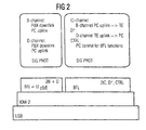
- a telephone essentially has three user interfaces, namely a microphone (acoustic source), a loudspeaker (acoustic sink) and a keyboard for the dialing process (D channel). These three user interfaces, possibly supplemented by further input and output units, are connected to the U p0 / E interface or S 0 interface to the private branch exchange (PABX) or the public telephone network via the internal IOM-2 bus (Input Output Multiplexer).
- the IOM-2 interface has a frame structure for three IOM channels. Each of these IOM channels provides four subchannels, each with 64 kbit / s.
- the IOM - 2 frame structure includes 2 B channels (64 KBit / s), a D channel (16 KBit / s), a D * channel (16 KBit / s), a CTRL channel (16 KBit / s) and 2 IC channels (64 KBit / s).
- the B channels are used to exchange data with the exchange, preferably voice data.
- the D channel is used to exchange control information with the exchange.
- the two IC channels are used for data exchange, preferably voice data, with other end devices, for example slave phones, and the D * and CTRL channel for the exchange of control information with other end devices.
- the phone connected to the exchange must be configured as the master phone.
- a communication system with at least one computer device, at least one telecommunication terminal and a switching device which can be connected to a public telecommunications network, the computer device and the telecommunication terminal being connected via a first bus system, the telecommunication terminal is connected to the switching device via an interface, the telecommunication terminal has a first operating mode in which the received data received from the switching device is converted by the telecommunication terminal to the first bus system and forwarded to the computer device via the first bus system, the computer device via devices for processing the data received from the telecommunication terminal and for forwarding them this data has the first bus system to the telecommunications terminal, the data being output by the telecommunications terminal, characterized in that the first bus system has a larger bandwidth than a second bus system that is used to connect individual internal assemblies of the telecommunication terminal, and that in the first operating mode the transmission data generated by the telecommunication terminal are also forwarded to a computer device via the first bus system, the computer device processes the received data by means of the processing device and forwards the processed transmission
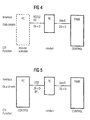
- the terminal (TE) which preferably represents a telephone, is physically connected to a private branch exchange (PABX) via a U p0 / E interface.
- the terminal can be connected to a public telephone network via another interface, for example an S 0 or U k0 interface.
- the PC and the terminal are physically preferably connected via a USB bus.
- FIG. 5 shows the cabling between PC, terminal (TE) and private branch exchange, which is required for the information exchange according to FIG. 1.
- the USB bus Since the USB bus is capable of the entire IOM-2 frame structure to transmit, the two IC channels, the two B channels to the private branch exchange and the D channel not only laboriously filtered out of the IOM-2 frame structure become. Because the entire IOM-2 frame structure is transferred to the PC, the PC can be the end device check completely. This also means that the data which the private branch exchange sends to the terminal (downlink) passed on to the PC in a simple manner. Furthermore, the PC by inserting data into the IOM-2 frame structure in simple data indirectly to the private branch exchange send. For direct communication between PC and end device there are two IC channels in each direction (uplink and Downlink).
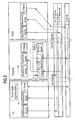
- the IOM-2 framework structure is not the complete one Bandwidth of the USB bus. Therefore, as in FIG. 6 shown via the USB bus to other peripheral devices the PC can be connected. For example, come here Loudspeakers, additional microphones, chip card readers, speed dial memory, Keyboards, mice and cameras for video telephony in question.
- the nesting of the respective layer 1 is shown in FIG Bit frame structures shown in the terminal.
- the bottom one Layer represents the USB bus.
- the IOM-2 layer corresponds to the Layer 1 of the OSI layer model towards the end device.
- Layer 1 of the OSI model becomes the PC through the USB bus shown.
- Layer 1 implementation of IOM / USB takes place in a layer 1 converter not shown here (e.g. plug-in adapter in phone).
- the LAP layer that of layer 2 of the OSI layer model equivalent.
- Layer 3 of the OSI layer model is referred to as the SIG PROT signaling protocol.
- the signaling protocol SIG PROT can be in two operating states are located. One operating state is the Symphony mode.
- the terminal In symphony mode (see Figure 4 and Figure 6) the terminal is controlled by the PABX private branch exchange.
- the second operating state is the butterfly mode (BFL) (see Figure 5 and Figure 7).
- BFL the butterfly mode
- this leads Terminal data only between PC and private branch exchange without responding to them.
- Data (language) between PC and Terminal devices are exchanged via the two IC channels.
- the terminal receives commands from the PC via the control channel (CTRL) (see also Figure 7). Control commands like Keystrokes, the phone can be connected to the D * channel Send PC.
- FIG. 6 shows the logical flow of information in Symphony mode.
- the terminal communicates with the private branch exchange via the U p0 / E interface.
- the bold connection to the private branch exchange indicates that the private branch exchange controls the terminal.
- the PC can communicate with peripheral devices via the USB bus and with the private branch exchange via the USB bus and the end device.
- the Symphony mode enables calls even when the PC is switched off. In symphony mode, the terminal is controlled by the private branch exchange.
- FIG. 7 shows the communication in butterfly mode.
- the end device (TE) is controlled from the PC via the USB bus. This is shown by the USB lines shown in bold.
- Data is only exchanged between the PC and the private branch exchange (PABX). This data is only passed through by the end device and implemented between the U p0 / E interface and the USB bus.
- the PC controls the end device via the control channel (CTRL). Keystrokes on the phone are transmitted to the PC via the D * channel.
- Data (voice) can be exchanged between the end device and the PC via the IC channels.
- the butterfly architecture enables preprocessing of data from the private branch exchange in the PC and the subsequent Output on the phone.
- Voice input via the phone in the PC before transmission the private branch exchange are preprocessed.
- the PC can carry out voice encryption. He would the voice data coming from the phone is encrypted to the Pass on the private branch exchange. Encrypted voice signals from the private branch exchange to the end device in plain text passed. Since there is only one B channel to the private branch exchange and an IC channel to the terminal is occupied, is the Parallel operation of another B channel application in the PC possible.
- the butterfly architecture is also suitable for the PC to implement an answering machine.
- the PC is drawing stand out due to high computing power and high storage capacity the hard drive. To implement an answering machine function it is therefore in the butterfly architecture sufficient to expand the software on the PC.
- the voice - Input and output is preferably again on the phone.
- other peripheral devices can be used, for example can be connected to the PC.
- the H.320 standard is a standard for narrowband image transmission. Since a screen is already available in the PC, only a camera is required to take the picture. This camera can be connected to the USB bus, for example.
- a B channel of the U p0 / E interface is used for video transmission. The second B channel is available for voice transmission (multiplexed with image data). Voice data is input and output via the phone.
- voice data is first exchanged between the PC and telephone via an IC channel. The PC sends the voice data to the private branch exchange via a B channel. The voice data is passed through the phone. This apparently complicated procedure makes it possible to keep the hardware expenditure, in particular in the telephone, as low as possible and to standardize the telephone software as far as possible.
Abstract
Description
Die vorliegende Erfindung betrifft ein Kommunikationssystem zum Anschließen zumindest eines Telekommunikationsendgeräts und zumindest einer Computereinrichtung an eine Vermittlungseinrichtung.The present invention relates to a communication system for connecting at least one telecommunications terminal and at least one computer device to a switching device.
Analoge Telefonanlagen werden zunehmend durch digitale ersetzt, die vorwiegend auf dem ISDN - Standard (Integrated Services Digital Network) beruhen. ISDN ist durch mehrere internationale digitale Kommunikationsstandards definiert, die weltweit von Telefongesellschaften anerkannt werden. Die ISDN-Technologie wird benutzt, um sowohl Sprache als auch Daten, die Graphiken, Töne und Filme umfassen können, digital Signale über öffentliche Fernmeldenetze zu senden. Der ISDN-Standard umfaßt digitale Standardübertragungsprotokolle, Anschlüsse und Verbindungskabel. Dem Benutzer stehen zwei Arten von ISDN-Anschlüssen zur Verfügung. Der international Basisanschluß (S0) umfaßt zwei B - Kanäle mit je 64 KBit/s und einen D - Kanal mit 16 KBit/s. Die B - Kanäle übertragen die Nutzinformation. Der D - Kanal wird für die Signalisierung verwendet. An einer S0 - Schnittstelle können dann bis zu acht Telefone oder andere Endgeräte betrieben werden.Analog telephone systems are increasingly being replaced by digital ones, which are mainly based on the ISDN standard (Integrated Services Digital Network). ISDN is defined by several international digital communication standards that are recognized worldwide by telephone companies. ISDN technology is used to digitally send both voice and data, which may include graphics, sounds and films, over public telecommunications networks. The ISDN standard includes standard digital transmission protocols, connections and connecting cables. Two types of ISDN connections are available to the user. The international basic connection (S 0 ) comprises two B channels with 64 Kbit / s each and one D channel with 16 Kbit / s. The B channels transmit the useful information. The D channel is used for signaling. Up to eight telephones or other end devices can then be operated on an S 0 interface.
Neben dem Basisanschluß (S0) steht der ebenfalls international genormte Primärmultiplexanschluß (S2M) zur Verfügung, der 30 B - Kanäle und 1 D - Kanal mit 64 KBit/s umfaßt.In addition to the basic connection (S 0 ), the internationally standardized primary multiplex connection (S 2M ) is also available, which comprises 30 B channels and 1 D channel with 64 kbit / s.
ISDN-Telefone können direkt an öffentlichen Netzen oder an privaten Nebenstellenanlagen (PABX, Private Automatic Brunch Exchange) betrieben werden. Öffentliche Kommunikationsnetze stellen in Deutschland üblicherweise zweidrähtige Uk0-Schnittstellen zur Verfügung. Diese Uk0 - Schnittstellen werden in einen sogenannten Netzabschluß (NT) in eine vierdrähtige S0 - Schnittstelle umgesetzt. Zum normalen Betrieb benötigt der Netzabschluß Energie aus dem öffentlichen Stromnetz. Bei Stromausfall versorgt der Netzabschluß (NT) ein notspeiseberechtigtes Endgerät mit Energie aus dem öffentlichen Telefonnetz. Der Notbetrieb wird durch eine Umkehr der Versorgungsspannung an der S0 - Schnittstelle angezeigt.ISDN telephones can be operated directly on public networks or on private branch exchanges (PABX, Private Automatic Brunch Exchange). In Germany, public communication networks usually provide two-wire U k0 interfaces. These U k0 interfaces are converted into a so-called network termination (NT) into a four-wire S 0 interface. For normal operation, the network termination requires energy from the public electricity network. In the event of a power failure, the network termination (NT) supplies an end device with emergency power supply with energy from the public telephone network. Emergency operation is indicated by a reversal of the supply voltage at the S 0 interface.
Endgeräte werden vorzugsweise über die Up0 - Schnittstelle an Nebenstellenanlagen angeschlossen. Die Up0 - Schnittstelle überträgt ebenfalls zwei B - Kanäle und einen D - Kanal. Die Up0 - Schnittstelle ist nicht international genormt. Deshalb existieren neben ihr viele andere herstellerspezifische U-Schnittstellen.Terminal devices are preferably connected to private branch exchanges via the U p0 interface. The U p0 interface also transmits two B channels and one D channel. The U p0 interface is not internationally standardized. That is why there are many other manufacturer-specific U interfaces in addition to it.
Da der ISDN - Standard ein digitaler Standard ist, können Computer besonders leicht über Einsteckkarten an ISDN-Schnittstellen angeschlossen werden. Im Gegensatz zur Sprachübertragung durch Telefone oder Bildübertragung durch Faxgeräte bieten Computer die Möglichkeit sehr unterschiedliche Datenformate zu übertragen. So werden im Bereich des Internets eine Vielzahl von Bildformaten, Sprachkompressions-verfahren bis hin zu Formaten zur Übertragung von bewegten Bildern verwendet. Es ist Stand der Technik, Faxe mit Computern zu verschicken und zu empfangen. Ein mit einem Drucker und einem Scanner verbundener Computer ersetzt mit der entsprechenden Software ein Faxgerät.Since the ISDN standard is a digital standard, Computer particularly easy using plug-in cards on ISDN interfaces be connected. In contrast to Voice transmission through phones or image transmission through Fax machines offer computers the possibility of very different Transfer data formats. So in the area of Internet a variety of image formats, voice compression processes to formats for the transmission of moving Images used. It is state of the art to fax with computers to send and receive. One with a printer and a scanner connected computer replaced with the corresponding one Software a fax machine.
Ein Problem in der gegenwärtigen PC-Welt ist die mangelnde Flexibilität der verwendeten Schnittstellen. Ein PC ist standardmäßig mit einer Tastaturschnittstelle, einer parallelen und zwei seriellen Schnittstellen (RS - 232) ausgerüstet. Die Tastaturschnittstelle ist durch die Tastatur belegt. Eine serielle Schnittstelle wird der Maus zugeordnet und die parallele Schnittstelle ist für den Drucker reserviert. Für weitere Peripheriegeräte steht nur die zweite serielle Schnittstelle zur Verfügung. Die Datenübertragung über eine serielle Schnittstelle ist im PC-Bereich auf maximal 115,2 KBit/s begrenzt. Deshalb werden Peripheriegeräte, die große Datenmengen produzieren, wie z.B. Scanner, über zusätzliche Einsteckkarten direkt an computerinterne Busse wie den PCI - Bus oder den ISA - Bus angeschlossen. Dazu ist es allerdings erforderlich, den Computer zu öffnen und weitere Einsteckkarten zu installieren. Ein weiterer Nachteil der vielen verschiedenen Schnittstellen im PC - Bereich liegt in der Verwendung vieler unterschiedlicher Steckverbindungen. Zur Lösung dieses Problems sind im Stand der Technik verschiedene Bussysteme bekannt. Im Unterschied zu den PCI - (Peripheral Component Interconnect) und ISA - (Industry Standard Architecture)-Bussen kann eine SCSI ( Small Computersystems Interface)-Schnittstelle auch aus dem Computergehäuse herausgeführt werden und so zum Anschluß von bis zu sieben Peripheriegeräte mit hohen Datenübertragungsraten, wie z.B. Festplatten oder Scanner verwendet werden. Im Niedrigpreissegment stehen eine Vielzahl von Bussen, wie z.B. der Apple Desktop Bus (ADB), die RS - 485 - Schnittstelle, die eine Erweiterung der RS-232 - Schnittstelle darstellt, der Access.bus (A.b), das Connection Highway Interface (CHI), der GeoPort und neuerdings der Universal Seriell Bus (USB) zur Verfügung.One problem in the current PC world is the lack Flexibility of the interfaces used. A PC is standard with a keyboard interface, a parallel one and two serial interfaces (RS - 232). The Keyboard interface is occupied by the keyboard. A serial Interface is assigned to the mouse and the parallel Interface is reserved for the printer. For further Peripheral devices only have the second serial interface to disposal. Data transmission via a serial The interface in the PC area is limited to a maximum of 115.2 kbps. This is why peripheral devices that have large amounts of data produce such as Scanner, via additional plug-in cards directly to computer internal buses like the PCI bus or connected to the ISA bus. However, this requires open the computer and insert additional cards to install. Another disadvantage of the many different ones Interfaces in the PC area lie in the use of many different plug connections. To solve this problem Various bus systems are known in the prior art. In contrast to the PCI - (Peripheral Component Interconnect) and ISA (Industry Standard Architecture) buses can be a SCSI (Small Computersystems Interface) interface also led out of the computer case and so for connecting up to seven peripheral devices with high data transfer rates, e.g. Hard drives or Scanner can be used. There are one in the low price segment Variety of buses, e.g. the Apple Desktop Bus (ADB), the RS-485 interface, which is an extension of the RS-232 - Interface represents the Access.bus (A.b), the Connection Highway Interface (CHI), the GeoPort and more recently the Universal Serial Bus (USB) is available.
Ein wesentliches Ziel bei der Definition des USB - Standards war ein niedrigpreisliches Bussystem zum Anschluß von externen Peripheriegeräten an PCs zur Verfügung zu stellen. Der USB - Bus bietet geringe bis mittlere Datenübertragungsraten (bis zu 12 MBit/s). Damit ist der USB - Bus hervorragend geeignet um eine Vielzahl von Peripheriegeräten, wie z.B. Scanner, Personal Digital Assistant (PDA), Tastaturen und Mäuse anzuschließen. An den USB - Bus können bis zu 127 Geräte angeschlossen werden. Ferner unterstützt der PCI - Bus die Plug - and - Play - Funktionalität. Die Verbindungskabel sind abschirmte Vierdrahtleitungen. Dabei werden zwei Drähte zur Übertragung einer Versorgungsspannung von 5 Volt verwendet. Die beiden anderen Drähte sind verdrillt und dienen der Signalübertragung. Für Datenübertragungsraten von 1,5 MBit/s sind ungeschirmte, unverdrillte Kabel ausreichend. Die Stecker sind so ausgelegt, daß ein Endgerät maximal 5 Ampere in die Versorgungsleitung des USB - Busses einspeisen kann. Die Energieversorgung über den USB - Bus bietet die Möglichkeit, Peripheriegeräte ohne Netzteile zu produzieren und damit Kosten zu sparen.An essential goal in the definition of the USB standard was a low-cost bus system for connecting external To provide peripheral devices on PCs. The USB bus offers low to medium data transfer rates (up to 12 Mbit / s). This makes the USB bus extremely suitable a variety of peripheral devices such as Scanner, Personal Digital Assistant (PDA), keyboards and mice to join. Up to 127 devices can be connected to the USB bus become. The PCI bus also supports the plug - and - play functionality. The connection cables are shielded Four-wire lines. Two wires are used to Transmission of a supply voltage of 5 volts used. The other two wires are twisted and are used for signal transmission. For data transfer rates of 1.5 Mbit / s unshielded, untwisted cables are sufficient. The Plugs are designed in such a way that a terminal device does not exceed 5 amps can feed into the supply line of the USB bus. The power supply via the USB bus offers the possibility To produce peripherals without power supplies and thereby saving costs.
PCs und weitere Endgeräte, wie z.B. Telefone, können gemeinsam an öffentliche Fernsprechnetze oder auch an private Nebenstellenanlagen angeschlossen werden. Sofern das öffentliche Fernsprechnetz oder die private Nebenstellenanlage eine Schnittstelle, wie z.B. die S0 - Schnittstelle oder die Up0-Schnittstelle zur Verfügung stellen, die den Anschluß mehrerer Endgeräte erlaubt, können PC und Endgerät an derselben Schnittstelle betrieben werden wie dies in Figur 3 angedeutet ist. Aus Kostengründen werden Telefone üblicherweise nur mit den nötigsten Funktionen ausgerüstet. Das Telefon bzw. Endgerät in Figur 3 kann deshalb nur Daten an die Nebenstellenanlage (PABX) senden und von der Nebenstellenanlage empfangen. Folglich ist in Figur 3 eine Kommunikation zwischen PC und Endgerät nur mittelbar über die Nebenstellenanlage (PABX) möglich. Es haben sich ferner herstellerspezifische Lösungen gemäß Figur 4 ausgebildet, wobei der PC beispielsweise über eine RS - 232 - Schnittstelle über ein Endgerät (TE) mit der Nebenstellenanlage (PABX) verbunden ist. Der Vorteil dieser Lösung besteht darin, daß auf PC - Seite auf eine bereits vorhandene Schnittstelle wie beispielsweise die RS - 232-Schnittstelle zurückgegriffen werden kann. Nachteilig ist, daß die genannten Schnittstelle nicht die für die vollständige Kontrolle durch den PC benötigte Bandbreite aufweist.PCs and other end devices, such as telephones, can be connected together to public telephone networks or to private branch exchanges. If the public telephone network or the private branch exchange provide an interface, such as the S 0 interface or the U p0 interface, which allows the connection of several terminals, the PC and terminal can be operated on the same interface as indicated in FIG. 3 is. For cost reasons, telephones are usually only equipped with the most necessary functions. The telephone or terminal in FIG. 3 can therefore only send data to the private branch exchange (PABX) and receive it from the private branch exchange. Consequently, communication between the PC and the terminal device is only possible indirectly via the private branch exchange (PABX) in FIG. 3. Manufacturer-specific solutions have also been developed in accordance with FIG. 4, the PC being connected to the private branch exchange (PABX), for example via an RS-232 interface, via a terminal (TE). The advantage of this solution is that an existing interface such as the RS-232 interface can be used on the PC side. It is disadvantageous that the interface mentioned does not have the bandwidth required for complete control by the PC.
Figur 3 zeigt ferner den internen Aufbau eines Telefons. Ein Telefon besitzt im wesentlichen drei Benutzerschnittstellen, nämlich ein Mikrophon (akust. Quelle), einen Lautsprecher (akust. Senke) und eine Tastatur für den Wählvorgang (D-Kanal). Diese drei Benutzerschnittstellen eventuell ergänzt durch weitere Ein- und Ausgabeeinheiten sind über den telefoninternen IOM-2 - Bus (Input Output Multiplexer) mit der Up0/E - Schnittstelle oder S0 - Schnittstelle zur Nebenstellenanlage (PABX) oder dem öffentlichen Fernsprechnetz verbunden. Die IOM-2 - Schnittstelle weist eine Rahmenstruktur für drei IOM - Kanäle auf. Jeder dieser IOM-Kanäle stellt vier Unterkanäle mit je 64 KBit/s zur Verfügung. In der IOM - 2 - Rahmenstruktur sind unter anderen 2 B - Kanäle (64 KBit/s), ein D - Kanal (16 KBit/s), ein D*-Kanal (16 KBit/s), ein CTRL - Kanal (16 KBit/s) und 2 IC-Kanäle (64 KBit/s) angelegt. Die B - Kanäle dienen dem Datenaustausch mit der Vermittlungsstelle vorzugsweise von Sprachdaten. Der D - Kanal dient zum Austausch von Kontrollinformationen mit der Vermittlungsstelle. Die beiden IC - Kanäle dienen dem Datenaustausch, vorzugsweise von Sprachdaten, mit weiteren Endgeräten, beispielsweise Slavephones, der D* und CTRL - Kanal dem Austausch von Kontrollinformationen mit weiteren Endgeräten. Bei der Verbindung mit weiteren Telefon (Slavephones) muß das Telefon, das mit der Vermittlungsstelle verbunden ist, als Masterphone konfiguriert werden.Figure 3 also shows the internal structure of a telephone. A telephone essentially has three user interfaces, namely a microphone (acoustic source), a loudspeaker (acoustic sink) and a keyboard for the dialing process (D channel). These three user interfaces, possibly supplemented by further input and output units, are connected to the U p0 / E interface or S 0 interface to the private branch exchange (PABX) or the public telephone network via the internal IOM-2 bus (Input Output Multiplexer). The IOM-2 interface has a frame structure for three IOM channels. Each of these IOM channels provides four subchannels, each with 64 kbit / s. The IOM - 2 frame structure includes 2 B channels (64 KBit / s), a D channel (16 KBit / s), a D * channel (16 KBit / s), a CTRL channel (16 KBit / s) and 2 IC channels (64 KBit / s). The B channels are used to exchange data with the exchange, preferably voice data. The D channel is used to exchange control information with the exchange. The two IC channels are used for data exchange, preferably voice data, with other end devices, for example slave phones, and the D * and CTRL channel for the exchange of control information with other end devices. When connecting to other phones (slave phones), the phone connected to the exchange must be configured as the master phone.
Aus US-A 4,748,656 ist eine Schnittstellenanordnung bekannt, die ein Kommunikationssystem mit einem Telekommunikationsendgerät verbindet. Diese Schnittstelle ist durch eine Einsteckkarte in einem Personalcomputer implementiert, welcher einerseits den Betrieb des angeschlossenen Telekommunikationsendgerätes steuert und andererseits Dienste des Kommunikationssystems bereitstellt. Die komplette Signalisierung aus dem Kommunikationssystem wird durch den Personalcomputer ausgewertet, in geeignete Steuersignale umgesetzt und an das Telekommunikationsendgerät weitergeleitet. Die vom Telekommunikationsendgerät empfangenen Daten werden im Personalcomputer ausgewertet und modifiziert. Hieraus werden geeignete Steuer- und Signalisierungsmeldungen abgeleitet, die dann vom Personalcomputer an das Kommunikationssystem weitergeleitet werden. Der Anschluß weiterer Peripheriegeräte an die Schnittstelle zwischen dem Personalcomputer und dem Telekommunikationsendgerät ist jedoch ebensowenig möglich, wie der Stand-alone-Betrieb des Telekommunikationsendgerätes bei ausgeschaltetem Personalcomputer.An interface arrangement is known from US Pat. No. 4,748,656, which is a communication system with a telecommunications terminal combines. This interface is through a plug-in card implemented in a personal computer, which on the one hand the operation of the connected telecommunications terminal controls and on the other hand services of the communication system provides. The complete signaling from the Communication system is evaluated by the personal computer, converted into suitable control signals and sent to the telecommunications terminal forwarded. The from the telecommunications terminal received data are stored in the personal computer evaluated and modified. Suitable tax and signaling messages derived from the personal computer forwarded to the communication system become. The connection of additional peripheral devices to the Interface between the personal computer and the telecommunications terminal is just as little possible as the Stand-alone operation of the telecommunications terminal switched off personal computer.
In "Isar - läßt Daten statt Wasser fließen" ELEKTRONIK Bd. 45, Nr. 20, 01. Oktober 1996, Seite 56 bis 60 ist ein Halbleiter-Baustein sowohl für die digitale als auch für die analoge Datenübertragung beschrieben. Dieser Baustein dient dem Bau kostengünstiger passiver ISDN-PC-Karten, die parallel zum Datentransfer mit ISDN-Teilnehmern auch mit Teilnehmern im analogen Netz kommunizieren und Daten übertragen können. Die Funktionen von passiven ISDN-PC-Karten, die auf dem dort beschriebenen Halbleiterbaustein basieren, sind mit denen aktiver Karten vergleichbar. In einem Anwendungsbeispiel ist der Halbleiterbaustein über einen IOM-2-Bus mit einem ISDN-Transceiver und über einen lokalen Bus mit einer PC-Bus-Schnittstelle verbunden.In "Isar - data flows instead of water" ELEKTRONIK Bd. 45, No. 20, October 01, 1996, pages 56 to 60 is a semiconductor device for both digital and analog Data transmission described. This block serves the Construction of inexpensive passive ISDN PC cards that run parallel to Data transfer with ISDN participants also with participants in can communicate analog network and transmit data. The Functions of passive ISDN PC cards on the there described semiconductor device are based on those comparable to active cards. In an application example is the semiconductor device via an IOM-2 bus with an ISDN transceiver and via a local bus with a PC bus interface connected.
Es ist die Aufgabe der vorliegenden Erfindung eine Lösung anzugeben, durch die ein PC und ein Telefon verbunden werden können, wobei dies mit geringem Hard- und Softwareaufwand erreicht werden soll und wobei über die Schnittstelle zwischen PC und Telefon weitere Peripheriegeräte anschließbar sein sollen.It is the object of the present invention to provide a solution through which a PC and a telephone are connected can, which is achieved with little hardware and software should be and where via the interface between PC and telephone can be connected to other peripheral devices should.
Diese Aufgabe wird gelöst durch ein Kommunikationssystem mit
mindestens einer Computereinrichtung, mindestens einem Telekommunikationsendgerät
und einer Vermittlungseinrichtung, die
an ein öffentliches Fernmeldenetz anschließbar ist, wobei
die Computereinrichtung und das Telekommunikationsendgerät
über ein erstes Bussystem verbunden sind,
das Telekommunikationsendgerät über eine Schnittstelle an die
Vermittlungseinrichtung angeschlossen ist,
das Telekommunikationsendgerät über einen ersten Betriebsmodus
verfügt, in dem die von der Vermittlungseinrichtung
empfangenen Empfangsdaten von dem Telekommunikationsendgerät
auf das erste Bussystem umgesetzt und über das erste
Bussystem an die Computereinrichtung weitergeleitet werden,
die Computereinrichtung über Einrichtungen zum Verarbeiten
der von dem Telekommunikationsendgerät empfangenen Daten und
zum Weiterleiten dieser Daten über das erste Bussystem an das
Telekommunikationsendgerät verfügt, wobei die Daten von dem
Telekommunikationsendgerät ausgegeben werden,
dadurch ge-kennzeichnet daß das erste Bussystem eine größere
Bandbreite aufweist als ein zweites Bussystem, das zur
Verbindung einzelner interner Baugruppen des Telekommunikationsendgerätes
verwendet wird, und daß in dem ersten
Betriebsmodus ferner die von dem Telekommunikationsendgerät
erzeuten Sendedaten über das erste Bussystem eine Computereinrichtung
weitergeleitet werden, die Computereinrichtung
die empfangenen Daten mittels der Verarbeitungseinrichtung
verarbeitet und die verarbeiteten Sendedaten über das erste
Bussystem an das Telekommunikationsendgerät zurückleitet und
das Telekommunikationsendgerät diese Daten zur Weiterleitung
an die Vermittlungseinrichtung auf die entsprechende Schnittstelle
umsetzt. This object is achieved by a communication system with at least one computer device, at least one telecommunication terminal and a switching device which can be connected to a public telecommunications network, the computer device and the telecommunication terminal being connected via a first bus system,
the telecommunication terminal is connected to the switching device via an interface,
the telecommunication terminal has a first operating mode in which the received data received from the switching device is converted by the telecommunication terminal to the first bus system and forwarded to the computer device via the first bus system, the computer device via devices for processing the data received from the telecommunication terminal and for forwarding them this data has the first bus system to the telecommunications terminal, the data being output by the telecommunications terminal,
characterized in that the first bus system has a larger bandwidth than a second bus system that is used to connect individual internal assemblies of the telecommunication terminal, and that in the first operating mode the transmission data generated by the telecommunication terminal are also forwarded to a computer device via the first bus system, the computer device processes the received data by means of the processing device and forwards the processed transmission data back to the telecommunication terminal via the first bus system and the telecommunication terminal converts this data for forwarding to the switching device on the corresponding interface.
Bevorzugte Ausgestaltungen der vorliegenden Erfindung sind Gegenstände der Unteransprüche.Preferred configurations of the present invention are Objects of the subclaims.
Im folgenden wird eine bevorzugte Ausführungsform der vorliegenden Erfindung unter Bezugnahme auf die beiliegenden Zeichnungen näher erläutert. Dabei zeigen:
Figur 1- eine erfindungsgemäße Kopplung zwischen PC und Endgerät
über den USB - Bus, wobei der PC indirekt über
USB und das PC-Endgerät über eine Up0/E - Schnittstelle
mit der Nebenstellenanlage (PABX) verbunden
sind, wobei die Bandbreite der USB-Schnittstelle um
mindestens die
Kanäle 2 IC, D* und CTRL größer ist als die Bandbreite der Upo-Schnittstelle. Figur 2- ein Schichtenmodell für das
Endgerät gemäß Figur 1, das sowohl im herkömmlichen Symphony - Mode (BRI) als auch im erfindungsgemäßen Butterfly - Mode (BFL) betrieben werden kann, - Figur 3
- den logischen Datenfluß bei herkömmlichem Anschluß
eines PCs und eines Endgeräts über eine S0 - Schnittstelle
oder eine Up0/E - Schnittstelle an eine Nebenstellenanlage
(PABX)
über 2 B - Kanäle und einen D-Kanal, - Figur 4
- eine herkömmliche Verkabelung bei Anschluß eines PCs über eine RS - 232 - oder S0 - Schnittstelle über ein Endgerät (TE) an eine Nebenstellenanlage,
- Figur 5
- eine erfindungsgemäß ausgestaltete Butterfly - Architektur, wobei PC und Endgerät (TE) über einen USB-Bus verbunden sind und Endgerät mit der Nebenstellenanlage (PABX) über eine Up0/E - Schnittstelle verbunden sind,
- Figur 6
- eine schematische Darstellung einer Datenübertragung in einer erfindungsgemäßen Butterfly - Architektur im Symphony - Mode, wobei das Endgerät in herkömmlicher Weise von der Nebenstellenanlage gesteuert wird und keine Daten direkt zwischen PC und Endgerät (TE) übertragen werden, und
- Figur 7
- eine schematische Darstellung einer Butterfly - Architektur im erfindungsgemäßen Butterfly - Mode, wobei das Endgerät (TE) vom PC gesteuert wird, wobei ferner das Endgerät die Daten zwischen der Nebenstellenanlage und PC nur weiterreicht und wobei, falls erforderlich, der PC wieder Daten über den USB - Bus an das Endgerät beispielsweise zur Lautsprecherausgabe weiterleitet.
- Figure 1
- a coupling according to the invention between PC and terminal via the USB bus, the PC being connected indirectly via USB and the PC terminal via a U p0 / E interface to the private branch exchange (PABX), the bandwidth of the USB interface being at least the
channels 2 IC, D * and CTRL is larger than the bandwidth of the U po interface. - Figure 2
- 2 shows a layer model for the terminal according to FIG. 1, which can be operated both in the conventional symphony mode (BRI) and in the butterfly mode (BFL) according to the invention,
- Figure 3
- the logical data flow with conventional connection of a PC and a terminal via an S 0 interface or a U p0 / E interface to a private branch exchange (PABX) via 2 B channels and a D channel,
- Figure 4
- conventional cabling when connecting a PC via an RS-232 or S 0 interface via a terminal (TE) to a private branch exchange,
- Figure 5
- a butterfly architecture designed according to the invention, the PC and the terminal (TE) being connected via a USB bus and the terminal being connected to the private branch exchange (PABX) via a U p0 / E interface,
- Figure 6
- a schematic representation of a data transmission in a butterfly architecture according to the invention in symphony mode, the terminal being controlled in a conventional manner by the private branch exchange and no data being transmitted directly between the PC and the terminal (TE), and
- Figure 7
- a schematic representation of a butterfly architecture in the butterfly mode according to the invention, the terminal (TE) being controlled by the PC, the terminal also only passing on the data between the private branch exchange and the PC and, if necessary, the PC again transmitting data via the USB - Forwards the bus to the terminal, for example for loudspeaker output.
Gemäß einer bevorzugte Ausführungsform der vorliegenden Erfindung die in Figur 1 gezeigt ist, ist das Endgerät (TE), das vorzugsweise ein Telefon darstellt, physikalisch über eine Up0/E - Schnittstelle mit einer Nebenstellenanlage (PABX) verbunden. Gemäß einer anderen Ausführungsform kann das Endgerät über eine andere Schnittstelle, beispielsweise eine S0- oderUk0 - Schnittstelle mit einem öffentlichen Fernsprechnetz verbunden sein. PC und Endgerät sind physikalisch vorzugsweise über einen USB - Bus verbunden. In Figur 5 ist die Verkabelung zwischen PC, Endgerät (TE) und Nebenstellenanlage dargestellt, die für den Informationsaustausch gemäß Figur 1 erforderlich ist.According to a preferred embodiment of the present invention, which is shown in FIG. 1, the terminal (TE), which preferably represents a telephone, is physically connected to a private branch exchange (PABX) via a U p0 / E interface. According to another embodiment, the terminal can be connected to a public telephone network via another interface, for example an S 0 or U k0 interface. The PC and the terminal are physically preferably connected via a USB bus. FIG. 5 shows the cabling between PC, terminal (TE) and private branch exchange, which is required for the information exchange according to FIG. 1.
Im Prinzip kommen für die physikalische Verbindung zwischen PC und Endgerät in Figur 1 alle bekannten Busse in Frage, die eine Bandbreite von (4x64 KBit/s + 16 KBit/s) (4 B - Kanäle und 1 D - Kanal) übertragen können. Allerdings fällt der Hardwareaufwand im Endgerät dann besonders gering aus, wenn die physikalische Schnittstelle zwischen PC und Endgerät die gesamte Bandbreite des IOM-2 - Busses, also die gesamte IOM-2 - Rahmenstruktur aufnehmen kann (Figur 2). Wie oben bereits erwähnt beträgt die Bandbreite des IOM-2 - Busses 12x64 KBit/s. Sie entspricht also 12 B - Kanälen oder insgesamt 768 KBit/s. Diese Bedingung erfüllen insbesondere die seriellen Schnittstellen (RS-232) und die S0 - Schnittstelle (Figur 4) nicht. Die erforderliche Bandbreite wird aber beispielsweise vom USB - Bus zur Verfügung gestellt.In principle, all known buses that can transmit a bandwidth of (4x64 KBit / s + 16 KBit / s) (4 B-channels and 1 D-channel) can be used for the physical connection between PC and terminal in FIG. 1. However, the hardware expenditure in the terminal is particularly low if the physical interface between the PC and the terminal can accommodate the entire bandwidth of the IOM-2 bus, that is to say the entire IOM-2 frame structure (FIG. 2). As already mentioned above, the bandwidth of the IOM-2 bus is 12x64 kbit / s. So it corresponds to 12 B channels or a total of 768 kbps. The serial interfaces (RS-232) and the S 0 interface (FIG. 4) in particular do not meet this condition. The required bandwidth is provided by the USB bus, for example.
Da der USB - Bus also in der Lage ist die gesamte IOM-2-Rahmenstruktur zu übertragen, müssen die beiden IC - Kanäle, die beiden B - Kanäle zur Nebenstellenanlage und der D - Kanal nicht erst aufwendig aus der IOM-2 - Rahmenstruktur herausgefiltert werden. Dadurch, daß die gesamte IOM-2 - Rahmenstruktur an den PC übertragen wird, kann der PC das Endgerät vollständig kontrollieren. Dadurch werden ferner die Daten, die die Nebenstellenanlage an das Endgerät schickt (Downlink) in einfacher Weise an den PC weitergereicht. Ferner kann der PC durch Einfügen von Daten in die IOM-2 - Rahmenstruktur in einfacher Weise Daten mittelbar an die Nebenstellenanlage senden. Für die direkte Kommunikation zwischen PC und Endgerät stehen zwei IC - Kanäle in jeder Richtung (Uplink und Downlink) zur Verfügung.Since the USB bus is capable of the entire IOM-2 frame structure to transmit, the two IC channels, the two B channels to the private branch exchange and the D channel not only laboriously filtered out of the IOM-2 frame structure become. Because the entire IOM-2 frame structure is transferred to the PC, the PC can be the end device check completely. This also means that the data which the private branch exchange sends to the terminal (downlink) passed on to the PC in a simple manner. Furthermore, the PC by inserting data into the IOM-2 frame structure in simple data indirectly to the private branch exchange send. For direct communication between PC and end device there are two IC channels in each direction (uplink and Downlink).
Die IOM-2 - Rahmenstruktur belegt nicht die vollständige Bandbreite des USB - Busses. Deshalb können wie in Figur 6 dargestellt über den USB - Bus weitere Peripheriegeräte an den PC angeschlossen werden. Hierfür kommen beispielsweise Lautsprecher, weitere Mikrophone, Chipkartenleser, Kurzwahlspeicher, Tastaturen, Mäuse und Kameras für die Bildtelefonie in Frage.The IOM-2 framework structure is not the complete one Bandwidth of the USB bus. Therefore, as in FIG. 6 shown via the USB bus to other peripheral devices the PC can be connected. For example, come here Loudspeakers, additional microphones, chip card readers, speed dial memory, Keyboards, mice and cameras for video telephony in question.
In Figur 2 ist die Verschachtelung der jeweiligen Schicht 1
Bitrahmenstrukturen im Endgerät dargestellt. Die unterste
Schicht stellt der USB - Bus dar. Über der USB - Schicht
liegt die IOM-2 - Schicht. Die IOM-2 - Schicht entspricht der
Schicht 1 des OSI - Schichtenmodells in Richtung Endgerät. In
Richtung PC wird die Schicht 1 des OSI-Modells durch den USB-Bus
dargestellt. Die Schicht 1 Umsetzung IOM/USB erfolgt in
einem hier nicht gezeigten Schicht 1 Konverter (z.B. Einsteckadapter
in Telefon). In Figur 2 nicht eingezeichnet ist
die LAP - Schicht, die der Schicht 2 des OSI - Schichtenmodells
entspricht. Schicht 3 des OSI - Schichtenmodells wird
als Signalisierungsprotokoll SIG PROT bezeichnet. Das Signalisierungsprotokoll
SIG PROT kann sich in zwei Betriebszuständen
befinden. Ein Betriebszustand ist der Symphony-Mode.
Im Symphony - Mode (siehe Figur 4 sowie Figur 6) wird
das Endgerät von der Nebenstellenanlage PABX gesteuert. Der
zweite Betriebszustand ist der Butterfly - Mode (BFL) (siehe
Figur 5 sowie Figur 7). Im Butterfly - Mode leitet das
Endgerät Daten nur zwischen PC und Nebenstellenanlage weiter
ohne auf diese zu reagieren. Daten (Sprache) zwischen PC und
Endgerät werden über die beiden IC - Kanäle ausgetauscht.
Befehle erhält das Endgerät vom PC über den Kontroll - Kanal
(CTRL) (siehe auch Figur 7). Steuerbefehle, wie
Tastatureingaben, kann das Telefon über den D* - Kanal an den
PC senden.The nesting of the
In Figur 6 ist der logische Informationsfluß im Symphony-Mode dargestellt. Das Endgerät kommuniziert mit der Nebenstellenanlage über die Up0/E - Schnittstelle. Die fett gezeichnete Verbindung zur Nebenstellenanlage weist darauf hin, daß die Nebenstellenanlage das Endgerät kontrolliert. Der PC kann einerseits mit Peripheriegeräten über den USB - Bus und mit der Nebenstellenanlage über den USB - Bus und das Endgerät kommunizieren. Der Symphony - Mode ermöglicht das Telefonieren auch bei ausgeschaltetem PC. Im Symphony - Mode wird das Endgerät durch die Nebenstellenanlage gesteuert.FIG. 6 shows the logical flow of information in Symphony mode. The terminal communicates with the private branch exchange via the U p0 / E interface. The bold connection to the private branch exchange indicates that the private branch exchange controls the terminal. The PC can communicate with peripheral devices via the USB bus and with the private branch exchange via the USB bus and the end device. The Symphony mode enables calls even when the PC is switched off. In symphony mode, the terminal is controlled by the private branch exchange.
In Figur 7 ist die Kommunikation im Butterfly - Mode dargestellt. Das Endgerät (TE) wird vom PC aus über den USB - Bus gesteuert. Dies ist durch die fett eingezeichneten USB - Leitungen dargestellt. Daten werden nur zwischen PC und Nebenstellenanlage (PABX) ausgetauscht. Diese Daten werden durch das Endgerät nur durchgeleitet und zwischen der Up0/E-Schnittstelle und dem USB - Bus umgesetzt. Der PC steuert das Endgerät über den Kontroll - Kanal (CTRL). Tastatureingaben auf dem Telefon werden über den D* - Kanal zum PC übermittelt. Daten (Sprache) können Endgerät und PC über die IC-Kanäle austauschen.FIG. 7 shows the communication in butterfly mode. The end device (TE) is controlled from the PC via the USB bus. This is shown by the USB lines shown in bold. Data is only exchanged between the PC and the private branch exchange (PABX). This data is only passed through by the end device and implemented between the U p0 / E interface and the USB bus. The PC controls the end device via the control channel (CTRL). Keystrokes on the phone are transmitted to the PC via the D * channel. Data (voice) can be exchanged between the end device and the PC via the IC channels.
Die Butterfly - Architektur ermöglicht die Vorverarbeitung von Daten aus der Nebenstellenanlage im PC und die anschließende Ausgabe auf dem Telefon. Umgekehrt kann beispielsweise Spracheingabe über das Telefon im PC vor der Weitergabe an die Nebenstellenanlage vorverarbeitet werden. Beispielsweise kann der PC Sprachverschlüsselung durchführen. Dabei würde er die vom Telefon kommenden Sprachdaten verschlüsselt an die Nebenstellenanlage weitergeben. Verschlüsselte Sprachsignale von der Nebenstellenanlage werden im Klartext an das Endgerät weitergegeben. Da jeweils nur ein B - Kanal zur Nebenstellenanlage und ein IC - Kanal zum Endgerät belegt werden, ist der Parallelbetrieb einer weiteren B - Kanalapplikation im PC möglich.The butterfly architecture enables preprocessing of data from the private branch exchange in the PC and the subsequent Output on the phone. Conversely, for example Voice input via the phone in the PC before transmission the private branch exchange are preprocessed. For example the PC can carry out voice encryption. He would the voice data coming from the phone is encrypted to the Pass on the private branch exchange. Encrypted voice signals from the private branch exchange to the end device in plain text passed. Since there is only one B channel to the private branch exchange and an IC channel to the terminal is occupied, is the Parallel operation of another B channel application in the PC possible.
Die Butterfly - Architektur eignet sich ferner dafür, auf dem PC einen Anrufbeantworter zu implementieren. Der PC zeichnet sich durch hohe Rechenleistung und hohe Speicherkapazität auf der Festplatte aus. Zur Implementierung einer Anrufbeantworterfunktion in die Butterfly - Architektur ist es deshalb ausreichend, die Software auf dem PC zu erweitern. Die Sprach - Ein- und -Ausgabe erfolgt vorzugsweise wieder über das Telefon. Alternativ dazu können weitere Peripheriegeräte beispielsweise an den PC angeschlossen werden.The butterfly architecture is also suitable for the PC to implement an answering machine. The PC is drawing stand out due to high computing power and high storage capacity the hard drive. To implement an answering machine function it is therefore in the butterfly architecture sufficient to expand the software on the PC. The voice - Input and output is preferably again on the phone. Alternatively, other peripheral devices can be used, for example can be connected to the PC.
Ein weiteres bevorzugtes Anwendungsfeld der Computer - Telefon - Integration mittels Butterfly - Architektur ist die Bildtelefonie. Mit dem Standard H.320 steht ein Standard für die schmalbandige Bildübertragung zur Verfügung. Da im PC schon ein Bildschirm zur Verfügung steht ist lediglich eine Kamera zur Bildaufnahme erforderlich. Diese Kamera kann beispielsweise an den USB - Bus angeschlossen werden. Gemäß dem H.320 - Standard wird ein B - Kanal der Up0/E - Schnittstelle für die Videoübertragung verwendet. Der zweite B - Kanal steht zur Sprachübertragung (gemultiplext mit Bilddaten) zur Verfügung. Sprachdaten werden über das Telefon ein- und ausgegeben. Gemäß der Butterfly - Architektur werden Sprachdaten zunächst zwischen PC und Telefon über einen IC - Kanal ausgetauscht. Der PC sendet die Sprachdaten über einen B - Kanal an die Nebenstellenanlage. Dabei werden die Sprachdaten durch das Telefon durchgeleitet. Dieses scheinbar komplizierte Verfahren ermöglicht es den Hardwareaufwand insbesondere im Telefon so gering wie möglich zu halten und die Telefonsoftware weitestgehend zu standardisieren.Another preferred field of application for computer-telephone integration using butterfly architecture is video telephony. The H.320 standard is a standard for narrowband image transmission. Since a screen is already available in the PC, only a camera is required to take the picture. This camera can be connected to the USB bus, for example. According to the H.320 standard, a B channel of the U p0 / E interface is used for video transmission. The second B channel is available for voice transmission (multiplexed with image data). Voice data is input and output via the phone. According to the Butterfly architecture, voice data is first exchanged between the PC and telephone via an IC channel. The PC sends the voice data to the private branch exchange via a B channel. The voice data is passed through the phone. This apparently complicated procedure makes it possible to keep the hardware expenditure, in particular in the telephone, as low as possible and to standardize the telephone software as far as possible.
Claims (12)
- Communication system comprising at least one computer device (PC), at least one telecommunication terminal (TE) and a switching device (PABX) which can be connected to a public telecommunication network, the computer device (PC) and the telecommunication terminal (TE) being connected via a first bus system (USB), the telecommunication terminal (TE) being connected to the switching device (PABX) via an interface (Up0/E), the telecommunication terminal having a first operating mode in which the received data received from the switching device are moved from the telecommunication terminal onto the first bus system (USB) and forwarded to the computer device (PC) via the first bus system, the computer device (PC) having devices for processing the data received from the telecommunication terminal and for forwarding these data to the telecommunication terminal via the first bus system, the data being output by the telecommunication terminal, characterized in that the first bus system (USB) has a greater bandwidth than a second bus system (IOM-2) which is used for connecting individual internal modules of the telecommunication terminal, and in that, in the first operating mode, the transmit data generated by the telecommunication terminal are also forwarded to a computer device (PC) via the first bus system (USB), the computer device processes the received data by means of the processing device and conducts the processed transmit data back to the telecommunication terminal via the first bus system, and the telecommunication terminal moves these data to the corresponding interface for forwarding to the switching device.
- Communication system according to Claim 1,
characterized in that the processing device of the computer device codes the transmit data generated by the telecommunication terminal and decodes the received data received from the switching device. - Communication system according to Claim 1 or 2,
characterized in that the first bus system is implemented by a USB bus and the second bus system is essentially implemented by an IOM-2 multiplexer and all data of the IOM-2 multiplexer are transmitted via the first bus system. - Communication system according to Claim 3,
characterized in that the computer device (PC) controls the telecommunication terminal in the first operating mode via a CTRL channel of the IOM-2 multiplexer, the computer device receives control information from the telecommunication terminal via a D* channel of the IOM-2 multiplexer, such as the information generated during the pressing of certain keys of the telecommunication terminal, and the computer device (PC) and the telecommunication terminal (TE) exchange data via IC channels of the IOM-2 multiplexer. - Communication system according to Claim 3 or 4,
characterized in that the telecommunication terminal moves the data only between the interface (Up0/E) and B channels of the IOM multiplexer. - Communication system according to one of Claims 1 to 5, characterized in that the switching device (PABX) is a private branch exchange.
- Communication system according to Claim 6,
characterized in that the interface (Up0/E) is a Up0/E interface. - Communication system according to one of Claims 1 to 7, characterized in that the telecommunication terminal has a second operating mode in which it is conventionally controlled by the private branch exchange, an operation independent of the computer device (PC) being possible in this operating mode.
- Communication system according to one of Claims 1 to 8, characterized in that the telecommunication terminal (TE) is a telephone.
- Communication system according to one of Claims 3 to 9, characterized in that the computer device (PC) has a program by means of which an answering machine simulation is made possible, the corresponding transmit data representing announcement texts and the computer device having devices for storing these transmit data in order to be able to forward the announcement texts with a time offset and repeatedly via the telecommunication terminal to the switching device, and the received data which represent messages from callers being sent to the computer device from the switching device (PABX) via the telecommunication terminal (TE), being temporarily stored in the computer device and reproduced with a time offset as received data via the telecommunication terminal.
- Communication system according to one of Claims 1 to 10, characterized in that the computer device (PC) has devices for performing video conferences or is connected to corresponding peripheral devices, the computer device receiving the received data from the switching device via the telecommunication terminal and dividing them in accordance with video data and voice data, displaying the video data on a screen of the computer device and sending the voice data back to the telecommunication terminal, and the computer device assembling transmit data or voice data and video data, the voice data being transmitted to the computer device from a microphone of the telecommunication terminal via the first bus system and the transmit data being sent to the switching device via the telecommunication terminal.
- Communication system according to one of Claims 1 to 11, characterized in that the switching device (PABX) corresponds to the ISDN standard.
Applications Claiming Priority (3)
| Application Number | Priority Date | Filing Date | Title |
|---|---|---|---|
| DE19741772 | 1997-09-22 | ||
| DE19741772 | 1997-09-22 | ||
| PCT/DE1998/002634 WO1999016176A2 (en) | 1997-09-22 | 1998-09-07 | Communication system |
Publications (2)
| Publication Number | Publication Date |
|---|---|
| EP1018287A2 EP1018287A2 (en) | 2000-07-12 |
| EP1018287B1 true EP1018287B1 (en) | 2002-01-30 |
Family
ID=7843223
Family Applications (1)
| Application Number | Title | Priority Date | Filing Date |
|---|---|---|---|
| EP98954133A Expired - Lifetime EP1018287B1 (en) | 1997-09-22 | 1998-09-07 | Communication system |
Country Status (5)
| Country | Link |
|---|---|
| US (1) | US7088709B1 (en) |
| EP (1) | EP1018287B1 (en) |
| CN (1) | CN1130949C (en) |
| DE (1) | DE59802979D1 (en) |
| WO (1) | WO1999016176A2 (en) |
Families Citing this family (5)
| Publication number | Priority date | Publication date | Assignee | Title |
|---|---|---|---|---|
| DE50208599D1 (en) * | 2002-07-23 | 2006-12-14 | Siemens Ag | Communication system and server for communication system |
| DE10240651A1 (en) * | 2002-09-03 | 2004-03-11 | Siemens Ag | Arrangement for voice and data communication via a common subscriber line |
| EP1496480A1 (en) * | 2003-07-11 | 2005-01-12 | Axalto S.A. | Device delivering a service using an associated portable memory, and relaying means for allowing activation of an application of the portable memory of the first device by a second device |
| DE102004030838A1 (en) * | 2004-06-25 | 2006-01-19 | Siemens Ag | Communication office |
| US8125911B2 (en) * | 2008-11-26 | 2012-02-28 | Cisco Technology, Inc. | First-hop domain reliability measurement and load balancing in a computer network |
Family Cites Families (16)
| Publication number | Priority date | Publication date | Assignee | Title |
|---|---|---|---|---|
| US4748656A (en) | 1986-03-21 | 1988-05-31 | American Telephone And Telegraph Company | Personal computer--as an interface between a telephone station set and a business communication system |
| FR2641093B1 (en) * | 1988-12-23 | 1994-04-29 | Alcatel Business Systems | |
| DE4008667A1 (en) | 1990-03-17 | 1991-09-19 | Telefonbau & Normalzeit Gmbh | CIRCUIT ARRANGEMENT FOR CONNECTING A COMPUTER TO A DIGITAL TELEPHONE |
| US5365577A (en) * | 1990-09-27 | 1994-11-15 | Radish Communications Systems, Inc. | Telecommunication display system |
| DE4221474C2 (en) * | 1992-06-30 | 1994-07-14 | Siemens Ag | Communication system for multi-service communication terminals in local area networks |
| US5287352A (en) * | 1992-07-17 | 1994-02-15 | Rolm Company | Method and apparatus to reduce register overhead in a serial digital interface |
| US5689553A (en) * | 1993-04-22 | 1997-11-18 | At&T Corp. | Multimedia telecommunications network and service |
| CA2109534A1 (en) * | 1993-11-19 | 1995-05-20 | Mauricio Peres | Interface device |
| US5483530A (en) * | 1993-12-16 | 1996-01-09 | International Business Machines Corporation | System and method for communicating with digital and analog devices via a single digital interface |
| EP0744087A4 (en) | 1994-02-10 | 1999-04-14 | Elonex Technologies Inc | Smart phone |
| CA2158408C (en) * | 1995-09-15 | 1998-12-08 | Graham H. Thompson | Architecture for robust voice cti |
| US5892764A (en) * | 1996-09-16 | 1999-04-06 | Sphere Communications Inc. | ATM LAN telephone system |
| US5974043A (en) * | 1996-09-16 | 1999-10-26 | Solram Electronics Ltd. | System and method for communicating information using the public switched telephone network and a wide area network |
| US6366653B1 (en) * | 1996-09-19 | 2002-04-02 | Acer Incorporated | System for integrating a telephone to a computer |
| US6081841A (en) * | 1998-02-10 | 2000-06-27 | Ricoh Company, Ltd. | Method and apparatus for expanding data rate in an ISDN communication system |
| US5995150A (en) * | 1998-02-20 | 1999-11-30 | Winbond Electronics Corporation America | Dual compressed video bitstream camera for universal serial bus connection |
-
1998
- 1998-09-07 US US09/509,049 patent/US7088709B1/en not_active Expired - Lifetime
- 1998-09-07 CN CN98809411A patent/CN1130949C/en not_active Expired - Fee Related
- 1998-09-07 WO PCT/DE1998/002634 patent/WO1999016176A2/en active IP Right Grant
- 1998-09-07 EP EP98954133A patent/EP1018287B1/en not_active Expired - Lifetime
- 1998-09-07 DE DE59802979T patent/DE59802979D1/en not_active Expired - Lifetime
Also Published As
| Publication number | Publication date |
|---|---|
| CN1271507A (en) | 2000-10-25 |
| WO1999016176A2 (en) | 1999-04-01 |
| DE59802979D1 (en) | 2002-03-14 |
| EP1018287A2 (en) | 2000-07-12 |
| WO1999016176A3 (en) | 1999-06-10 |
| CN1130949C (en) | 2003-12-10 |
| US7088709B1 (en) | 2006-08-08 |
Similar Documents
| Publication | Publication Date | Title |
|---|---|---|
| DE69434646T2 (en) | Network with digital and analog outputs | |
| DE3405286C2 (en) | ||
| CH662025A5 (en) | DIGITAL SWITCHING SYSTEM. | |
| DE19542122B4 (en) | Local communication server system | |
| EP0687402B1 (en) | Circuit arrangement for integrating edp systems in the use of telephone installations | |
| DE19820382A1 (en) | Method and device for dynamic bandwidth allocation to independent data and audio devices | |
| DE19937098A1 (en) | Intelligent allocation of bandwidth for several independent connections on a digital network involves sending link establishment message from source terminal to digital network exchange | |
| DE4131062C1 (en) | ||
| EP0581087B1 (en) | Method for representing subscriber's individual data when transmitting signalling signals and information signals between narrow band networks and ATM-networks | |
| EP1018287B1 (en) | Communication system | |
| EP0303870A2 (en) | Modular structured digital communication system with operational and reliable components | |
| EP0734186B1 (en) | Method for controlling an access network and an access network and an exchange therefor | |
| EP1016312A2 (en) | Method and device for automatic translation of messages in a communications system | |
| DE3336641A1 (en) | CIRCUIT ARRANGEMENT FOR CONTROLLABLE CONNECTING IN A PCM SWITCHING SYSTEM | |
| DE4116057C1 (en) | ||
| EP0127138A2 (en) | Telecommunication system linked to an information processing system | |
| DE4124118A1 (en) | Communications network with local exchange connected to integrated services digital network - has multiplexer between analogue subscribers and two-wire terminal coupled to digital exchange | |
| DE69731613T2 (en) | DEVICE AND METHOD FOR PRODUCING COMPOUNDS | |
| AT390857B (en) | CIRCUIT ARRANGEMENT FOR MEDIATING DATA SIGNALS DIFFERENT DATA SIGNAL RATES IN A DATA SWITCHING SYSTEM | |
| DE19745026A1 (en) | Computer phone integration system | |
| DE19914511B4 (en) | Switching device with ISDN connection | |
| DE3405011C1 (en) | Circuit arrangement for operating two-wire digital connection and/or junction lines on a telecommunications switching system | |
| EP0596296B1 (en) | Digital telecommunication exchange with connection possibility for one or more external computers | |
| EP0440062A2 (en) | Connection state recognizing in a broad band private communication exchange | |
| EP1168789A2 (en) | Direct connection between the switching matix of a CTI-Server and a telecommunications exchange |
Legal Events
| Date | Code | Title | Description |
|---|---|---|---|
| PUAI | Public reference made under article 153(3) epc to a published international application that has entered the european phase |
Free format text: ORIGINAL CODE: 0009012 |
|
| 17P | Request for examination filed |
Effective date: 20000317 |
|
| AK | Designated contracting states |
Kind code of ref document: A2 Designated state(s): DE FR GB IT |
|
| GRAG | Despatch of communication of intention to grant |
Free format text: ORIGINAL CODE: EPIDOS AGRA |
|
| GRAG | Despatch of communication of intention to grant |
Free format text: ORIGINAL CODE: EPIDOS AGRA |
|
| GRAH | Despatch of communication of intention to grant a patent |
Free format text: ORIGINAL CODE: EPIDOS IGRA |
|
| 17Q | First examination report despatched |
Effective date: 20010711 |
|
| GRAH | Despatch of communication of intention to grant a patent |
Free format text: ORIGINAL CODE: EPIDOS IGRA |
|
| GRAA | (expected) grant |
Free format text: ORIGINAL CODE: 0009210 |
|
| REG | Reference to a national code |
Ref country code: GB Ref legal event code: IF02 |
|
| AK | Designated contracting states |
Kind code of ref document: B1 Designated state(s): DE FR GB IT |
|
| REF | Corresponds to: |
Ref document number: 59802979 Country of ref document: DE Date of ref document: 20020314 |
|
| GBT | Gb: translation of ep patent filed (gb section 77(6)(a)/1977) |
Effective date: 20020407 |
|
| ET | Fr: translation filed | ||
| PLBE | No opposition filed within time limit |
Free format text: ORIGINAL CODE: 0009261 |
|
| STAA | Information on the status of an ep patent application or granted ep patent |
Free format text: STATUS: NO OPPOSITION FILED WITHIN TIME LIMIT |
|
| 26N | No opposition filed | ||
| PGFP | Annual fee paid to national office [announced via postgrant information from national office to epo] |
Ref country code: DE Payment date: 20101124 Year of fee payment: 13 |
|
| PGFP | Annual fee paid to national office [announced via postgrant information from national office to epo] |
Ref country code: GB Payment date: 20110923 Year of fee payment: 14 Ref country code: FR Payment date: 20111005 Year of fee payment: 14 |
|
| PGFP | Annual fee paid to national office [announced via postgrant information from national office to epo] |
Ref country code: IT Payment date: 20110927 Year of fee payment: 14 |
|
| REG | Reference to a national code |
Ref country code: GB Ref legal event code: 732E Free format text: REGISTERED BETWEEN 20121025 AND 20121031 |
|
| REG | Reference to a national code |
Ref country code: FR Ref legal event code: TP Owner name: SIEMENS ENTERPRISE COMMUNICATIONS GMBH & CO. K, DE Effective date: 20130108 |
|
| REG | Reference to a national code |
Ref country code: DE Ref legal event code: R082 Ref document number: 59802979 Country of ref document: DE Representative=s name: FRITZSCHE PATENT, DE |
|
| REG | Reference to a national code |
Ref country code: DE Ref legal event code: R082 Ref document number: 59802979 Country of ref document: DE Representative=s name: FRITZSCHE PATENT, DE Effective date: 20130313 Ref country code: DE Ref legal event code: R081 Ref document number: 59802979 Country of ref document: DE Owner name: SIEMENS ENTERPRISE COMMUNICATIONS GMBH & CO. K, DE Free format text: FORMER OWNER: SIEMENS AKTIENGESELLSCHAFT, 80333 MUENCHEN, DE Effective date: 20130313 |
|
| GBPC | Gb: european patent ceased through non-payment of renewal fee |
Effective date: 20120907 |
|
| REG | Reference to a national code |
Ref country code: FR Ref legal event code: ST Effective date: 20130531 |
|
| REG | Reference to a national code |
Ref country code: DE Ref legal event code: R119 Ref document number: 59802979 Country of ref document: DE Effective date: 20130403 |
|
| PG25 | Lapsed in a contracting state [announced via postgrant information from national office to epo] |
Ref country code: GB Free format text: LAPSE BECAUSE OF NON-PAYMENT OF DUE FEES Effective date: 20120907 Ref country code: DE Free format text: LAPSE BECAUSE OF NON-PAYMENT OF DUE FEES Effective date: 20130403 |
|
| PG25 | Lapsed in a contracting state [announced via postgrant information from national office to epo] |
Ref country code: FR Free format text: LAPSE BECAUSE OF NON-PAYMENT OF DUE FEES Effective date: 20121001 Ref country code: IT Free format text: LAPSE BECAUSE OF NON-PAYMENT OF DUE FEES Effective date: 20120907 |
|
| REG | Reference to a national code |
Ref country code: FR Ref legal event code: CD Owner name: UNIFY GMBH & CO.KG, DE Effective date: 20140429 |