EP1385254A2 - Electric motor - Google Patents
Electric motor Download PDFInfo
- Publication number
- EP1385254A2 EP1385254A2 EP03253858A EP03253858A EP1385254A2 EP 1385254 A2 EP1385254 A2 EP 1385254A2 EP 03253858 A EP03253858 A EP 03253858A EP 03253858 A EP03253858 A EP 03253858A EP 1385254 A2 EP1385254 A2 EP 1385254A2
- Authority
- EP
- European Patent Office
- Prior art keywords
- cables
- introducing member
- cable introducing
- electric
- electric motor
- Prior art date
- Legal status (The legal status is an assumption and is not a legal conclusion. Google has not performed a legal analysis and makes no representation as to the accuracy of the status listed.)
- Granted
Links
Images






Classifications
-
- H—ELECTRICITY
- H02—GENERATION; CONVERSION OR DISTRIBUTION OF ELECTRIC POWER
- H02K—DYNAMO-ELECTRIC MACHINES
- H02K5/00—Casings; Enclosures; Supports
- H02K5/04—Casings or enclosures characterised by the shape, form or construction thereof
- H02K5/22—Auxiliary parts of casings not covered by groups H02K5/06-H02K5/20, e.g. shaped to form connection boxes or terminal boxes
- H02K5/225—Terminal boxes or connection arrangements
Definitions
- the present invention relates to an electric motor, and in particular to an improvement of structure for connecting electric cables with internal cables of the electric motor.
- electric cables such as power cables are connected to terminals of internal cables of an electric motor for supplying electricity to the motor and other purposes.
- a high degree of freedom in selecting a direction of the approach and connection of the electric cables has been required by factors such as design of the motor, direction of installation of the motor, and relative position of the motor with respect to a plug socket.
- Electric cables for power supply are difficult to handle in wiring work since they are generally thick and hard. Further, there is not a sufficient space for the wiring work in a machine into which the electric motor is already assembled. Thus, it is desirable to have a high degree of freedom in selecting a direction of approach and connection of the electric cables to the electric motor in order to facilitate the wiring work.
- An object of the present invention is to provide an electric motor having a sufficient degree of freedom in selecting a direction of approach and connection for an electric cable to an internal cable of the motor.
- An electric motor of the present invention comprises: a body containing internal cables; and a cable introducing member having a through hole for introducing electric cables for connection with the internal cables.
- the cable introducing member is mounted on the body to have one of a plurality of different orientations such that a position of the through hole relative to the body is selectable from a plurality of different positions.
- a high degree of freedom is secured in selecting a direction of approach and connection of the electric cables to the electric motor using the same cable introducing member, without forming redundant through holes for obtaining the high degree of freedom.
- ingress of water and dust into the motor from unused through holes is prevented and it is not necessary to close unused through holes.
- the position of the through hole relative to the body of the electric motor may be changed by detaching the cable introducing member from the body and mounting the cable introducing member again on the body to have a different orientation.
- the plurality of orientations of the cable introducing member may be angularly displaced by a predetermined angle.
- the cable introducing member may have a cross section of a regular polygon, or an annular cross section.
- the electric motor may further comprise a terminal rest fixed to the body for allowing connection of the electric cables with the internal cables in at least two different directions.
- the terminal rest may have a plurality of terminals including an upper terminal and a lower terminal positioned at different heights.
- a base member 3 of a terminal case is fixed on a body 1 of an electric motor having an output shaft 2.
- a cable introducing member 10 is mounted on the body 1 by fixing four corners of the member 10 to the base member 3 by screws 12.
- the cable introducing member 10 is a hollow rectangular prism having a square cross-section and four side walls.
- a through hole 11 for inserting the electric cables is formed on one of the side walls of the cable introducing member 10.
- the cable introducing member 10 is easily attached to and detached from the body 1 by turning the screw 12 at the four corners.
- the cable introducing member 10 can take one of four different orientations angularly displaced by 90° since the cable introducing member 10 has a square cross-section.
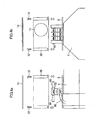
- FIGS. 1, 2a and 2b show three mounting statuses of the cable introducing member 10 on the body 1.
- FIGS. 2a and 2b show orientations of the cable introducing member 10 angularly displacing the orientation of the cable introducing member 10 as shown in FIG. 1 by 90° and 180°, respectively.
- One of the four orientations of the cable introducing member 10 is selected in accordance with approach direction of the electric cables (direction of introducing the electric cable into the terminal case).
- the orientation of the cable introducing member 10 is selected so that the through hole 11 formed in one of the side walls is positioned in conformity with approach direction of the external electric cables.
- FIGS. 3, 4a and 4b The connection of the electric cables introduced from the insertion hole 11 with the internal cables is shown in FIGS. 3, 4a and 4b.
- a terminal rest 15 for the connection of the electric cables 90 with internal cables 80 is fixed to the base member 3 at an approximately central position of the base member 3.
- the terminal rest 15 includes terminals for internal cables 80 and electric cables 90 to be connected to the internal cables 80, and the internal cables 80 and the associated electric cables 90 are fixed to the terminals by screws to be connected with one another.
- the terminal rest 15 has a plurality of pairs of terminals. Each pair comprises an upper terminal to which the electric cable 90 is connected, and a lower terminal to which the internal cable 80 is connected, which are electrically connected to each other.
- the electric cables 90 may be connected to the upper terminal in a direction as indicated by a broken line 91 which is opposite to the direction of the electric cables 90 as indicated by the solid line.
- One of the connecting directions of the electric cable 90 may be selected in accordance with the orientation of the cable introducing member 10.
- the connecting direction of the electric cables 90 is selected so that the electric cables 90 reach the upper terminals from the insertion hole 11 without being bent sharply.
- the orientation of the cable introducing member 10 as shown in FIG. 1 or FIG. 2b is suitable for the arrangement of the terminal rest 15 in this embodiment.
- a lid member 13 is provided for covering a top opening of the cable introducing member 10.
- the lid member 13 is mounted on the cable introducing member 10 by appropriate engaging means such as screws or hinges so as to close the top opening of the cable introducing member 10, and also expose the connection portions of the electric cables 90 and the internal cables 80 by releasing the engagement by the engaging means for the connection work of the electric cables 90 with the upper terminals and maintenance of cleaning and inspection of the connecting portions.
- the lid member 13 is omitted for convenience of depiction.
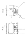
- FIGS. 5, 6a and 6b A second embodiment of the present invention will be described referring to FIGS. 5, 6a and 6b.
- the second embodiment is a modification of the first embodiment and the structure and the mounting manner of the cable introducing member 10 are the same as those in the first embodiment.
- the cable introducing member 10 is in the form of a hollow rectangular prism having a square cross-section and four side walls and corners.
- the cable introducing member 10 is mounted on the body 1 of the electric motor to take one of four different orientations angularly displaced by 90° such that the through hole 11 formed on one side wall is positioned in conformity with the approaching direction of the electric cables 90.
- the second embodiment differs from the first embodiment in a structure of a terminal rest for the connection of the electric cables 90 and the internal cables 80.
- a terminal rest 25 of this embodiment is fixed at an approximately central position of the base member 3, as shown in FIG. 5.
- the terminal rest 25 includes terminals corresponding to the internal cables 80 and the associated electric cables 90, and the internal cables 80 and the associated electric cables 90 are fixed to the terminals by screws to be connected with one another.
- the terminal rest 25 has a plurality of pairs of terminals, each comprising an upper terminal to which the electric cable 90 is connected and a lower terminal to which the internal cable 80 is connected.
- a conducting piece 26 for electrically connecting the upper terminal and the associated lower terminal is formed into a U-shape so that connection work of the internal cable 80 to the lower terminal by turning screws 27 can be carried out from upward of the terminal rest 25. With this arrangement, the connection work of the internal cables 80 with the lower terminals are made easy.
- the electric cables 90 may be connected to the upper terminal in a direction as indicated by a broken line 91 which is opposite to the direction of the electric cables 90 as indicated by the solid line, as in the first embodiment.
- One of the connecting directions of the electric cable 90 may be selected in accordance with the orientation of the cable introducing member 10. In general, the connecting direction of the electric cables 90 is selected so that the electric cables 90 reach the upper terminals from the insertion hole 11 without being bent sharply.
- a lid member 13 is provided for covering a top opening of the cable introducing member 10.
- the lid member 13 is mounted on the cable introducing member 10 by appropriate engaging means such as screws or hinges so as to close the top opening of the cable introducing member 10, and also expose the connection portions of the electric cables 90 and the internal cables 80 by releasing the engagement by the engaging means for the connection work of the electric cables 90 with the upper terminals and maintenance of cleaning and inspection of the connecting portions.
- FIGS. 7, 8a and 8b A third embodiment of the present invention will be described referring to FIGS. 7, 8a and 8b.
- the second embodiment is another modification of the first embodiment and the structure and the mounting manner of the cable introducing member 10 are the same as those in the first embodiment.
- the cable introducing member 10 is in the form of a hollow rectangular prism having a square cross-section and four side walls and comers.
- the cable introducing member 10 is mounted on the body 1 of the electric motor to take one of four different orientations angularly displaced by 90° such that the through hole 11 formed on one side wall is positioned in conformity with the approaching direction of the electric cables 90.
- the third embodiment differs from the first and second embodiments in a structure of a terminal rest for the connection of the electric cables 90 and the internal cables 80.
- a terminal rest 35 of this embodiment is fixed at an approximately central position of the base member 3, as shown in FIG. 5.
- the terminal cables 80 extend upwardly from lower side of the terminal rest 35 and are directly connected with respective terminals for connection with the electric cables 90. According to this embodiment, the connections between the terminals of the terminal rest 35 and the internal cables 80 are secured in advance and thus the connection work for connecting the internal cables 80 with the terminals is not necessary in this assembly of the electric motor.
- the electric cables 90 may be connected to the terminals in a direction as indicated by a broken line 91 which is opposite to the direction of the electric cables 90 as indicated by the solid line, as in the first and second embodiments.
- One of the connecting directions of the electric cable 90 may be selected in accordance with the orientation of the cable introducing member 10. In general, the connecting direction of the electric cables 90 is selected so that the electric cables 90 reach the terminals from the insertion hole 11 without being bent sharply.
- the cable introducing member 10 having a square cross-section is adopted to realize "four" degree of freedom of orientation of the cable introducing member which are angularly displaced by 90°.
- the degree of freedom of orientation of the cable introducing member can be increased.
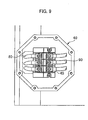
- a fourth embodiment of the present invention as shown in FIGS. 9, 10a and 10b is an example of an electric motor in which the degree of freedom is further increased.
- This embodiment is featured by a cable introducing member 40 having a cross-section of a regular octagon in place of the cable introducing member 10 having a square cross-section.
- the cable introducing member 40 is mounted on the body 1 of the electric motor to take one of eight different orientations angularly displaced by 45° such that the through hole 11 formed on one side wall is positioned in conformity with the approaching direction of the electric cables 90, so that "eight" degree of freedom of orientation of the cable introducing member 40 is realized.
- a terminal rest 45 has a plurality of pairs of terminals, each comprising an upper terminal to which the electric cable 90 is connected and a lower terminal to which the internal cable 80 is connected.
- a conducting piece for electrically connecting the upper terminal and the associated lower terminal has a U-shape so that connection work of the internal cable 80 to the lower terminal by turning screws can be carried out from upward of the terminal rest 45.
- the electric cables 90 may be connected to the upper terminal in a direction as indicated by a broken line 91 which is opposite to the direction of the electric cables 90 as indicated by the solid line in FIG. 10b.
- One of the connecting directions of the electric cable 90 may be selected in accordance with the orientation of the cable introducing member 10. In general, the connecting direction of the electric cables 90 is selected so that the electric cables 90 reach the upper terminals from the insertion hole 11 without being bent sharply.
- a lid member 43 is formed into a regular octagon shape in conformity with the cross-section of the regular octagon of the cable introducing member 40.
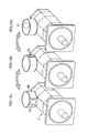
- a fifth embodiment of the present invention as shown in FIGS. 11-13c is an example of an electric motor in which the degree of freedom of orientation of the cable introducing member is further increased.
- This embodiment is featured by a cable introducing member 50 in a form of a hollow cylinder having an annular cross-section.
- a through hole 51 for introducing the electric cables 90 is formed on an annular wall of the hollow cylinder.
- the cable introducing member 50 is mounted on the base member 3 in a manner different from that of the cable introducing members 10 and 40, as follows;
- An annular guide 31 having an outer circumference conformable to an inner circumference of the cable introducing member 50 is formed on the base member 3.
- the inner circumference of the cable introducing member 50 is fitted into the outer circumferences of the guides 31 to mount the cable introducing member 50 of the base member 3.
- the guide 31 may comprise a ring formed continuously or arc segments formed periodically which has an outer diameter slightly smaller than the inner diameter of the cylindrical cable introducing member 50.
- the orientation of the cable introducing member 50 is arbitrarily selected by sliding the cylindrical cable introducing member 50 along the annular guide 31.
- degree of freedom of the orientation of the cable introducing member 50 is infinite in this embodiment.
- a part or the whole of the base member 3, e.g. only the annular guide 31, and the cable introducing member 50 may be formed by magnetic material (for example, the annular guide 31 is formed by permanent magnet and the cable introducing member 50 is formed by ferruginous material) in order to fix the selected angular position of the cable introducing member 50.
- FIGS. 13a-13c show three different orientations of the cable introducing member 50 mounted on the electric motor.
- a terminal rest 55 has a plurality of pairs of terminals, each comprising an upper terminal to which the electric cable 90 is connected, and a lower terminal to which the internal cable 80 is connected.
- a conducting piece for electrically connecting the upper terminal and the associated lower terminal is provided in the terminal rest 55.
- the electric cables 90 may be connected to the upper terminal in a direction as indicated by a broken line 91 which is opposite to the direction of the electric cables 90 as indicated by the solid line in FIG. 12a.
- One of the connecting directions of the electric cable 90 may be selected in accordance with the orientation of the cable introducing member 10. In general, the connecting direction of the electric cables 90 is selected so that the electric cables 90 reach the upper terminals from the insertion hole 11 without being bent sharply.
- a lid member 53 is formed into a circular shape in conformity with the annular cross-section of the cable introducing member 50.
- a position of a through hole for introducing electric cable to be connected with internal cables, relative to a body of an electric motor, is selectable from a plurality of different positions by a cable introducing member mounted on the body to have one of a plurality of different orientations. Therefore, a high degree of freedom is secured in selecting a direction of the approach and connection of the electric cables to the electric motor of the same kind using the same cable introducing member. Further, it is not necessary to form redundant through holes for obtaining the high degree of freedom in selecting the approaching and connecting the electric cables. Thus, ingress of water and dust into the motor from unused through holes is prevented and it is not necessary to close unused through holes.
- the cable introducing member 10 is described and illustrated as being detachably mounted on the body 1 for changing its orientation, it will be appreciated that in alternative embodiments the cable introducing member 10 may be mounted non-detachably on the body 1, but in a manner which will nevertheless permit the cable introducing member 10 to change its orientation.
Landscapes
- Engineering & Computer Science (AREA)
- Power Engineering (AREA)
- Motor Or Generator Frames (AREA)
Abstract
Description
Claims (7)
- An electric motor to be connected to electric cables, comprising:a body containing internal cables; anda cable introducing member having a through hole for introducing the electric cables for connection with the internal cables, said cable introducing member being mounted on said body to have one of a plurality of different orientations such that a position of the through hole relative to said body is selectable from a plurality of different positions.
- An electric motor according to claim 1, wherein the plurality of orientations of said cable introducing member are angularly displaced by a predetermined angle.
- An electric motor according to claim 1 or 2, wherein said cable introducing member has a cross section of a regular polygon.
- An electric motor according to claim 1 or 2, wherein said cable introducing member has an annular cross section.
- An electric motor according to any preceding claim, further comprising a terminal rest fixed to said body for allowing connection of the electric cables with the internal cables in at least two different directions.
- An electric motor according to claim 5, wherein said terminal rest has a plurality of terminals including an upper terminal and a lower terminal positioned at different heights.
- An electric motor according to any preceding claim, wherein the cable introducing member is detachably mounted on said body to have said plurality of different orientations.
Applications Claiming Priority (2)
| Application Number | Priority Date | Filing Date | Title |
|---|---|---|---|
| JP2002212631A JP2004056943A (en) | 2002-07-22 | 2002-07-22 | Motor |
| JP2002212631 | 2002-07-22 |
Publications (3)
| Publication Number | Publication Date |
|---|---|
| EP1385254A2 true EP1385254A2 (en) | 2004-01-28 |
| EP1385254A3 EP1385254A3 (en) | 2005-06-01 |
| EP1385254B1 EP1385254B1 (en) | 2008-07-30 |
Family
ID=29997213
Family Applications (1)
| Application Number | Title | Priority Date | Filing Date |
|---|---|---|---|
| EP03253858A Expired - Lifetime EP1385254B1 (en) | 2002-07-22 | 2003-06-18 | Electric motor |
Country Status (4)
| Country | Link |
|---|---|
| US (1) | US6828704B2 (en) |
| EP (1) | EP1385254B1 (en) |
| JP (1) | JP2004056943A (en) |
| DE (1) | DE60322480D1 (en) |
Cited By (3)
| Publication number | Priority date | Publication date | Assignee | Title |
|---|---|---|---|---|
| US7045911B2 (en) * | 2003-12-16 | 2006-05-16 | F.G. Wilson | Electric power generation arrangement with rotary cabling guide |
| DE102005046120A1 (en) * | 2005-09-26 | 2007-03-29 | Wilo Ag | Housing of an electric motor |
| EP2639943B1 (en) | 2012-03-15 | 2015-02-25 | Grundfos Holding A/S | Electric motor |
Families Citing this family (21)
| Publication number | Priority date | Publication date | Assignee | Title |
|---|---|---|---|---|
| US6933638B2 (en) * | 2003-10-30 | 2005-08-23 | A. O. Smith Corporation | Electric motor having a reverse air flow cooling system |
| EP1715562B1 (en) * | 2005-04-22 | 2012-11-14 | Infranor Holding S.A. | Connection system for electric motors |
| US8424187B2 (en) | 2005-04-22 | 2013-04-23 | Infranor Holding Sa | Method of terminating the stator winding of an electric motor |
| US7572114B2 (en) * | 2005-06-21 | 2009-08-11 | Sonic Tractor Parts, Inc. | Structure of pump |
| JP5103266B2 (en) * | 2008-05-12 | 2012-12-19 | オリエンタルモーター株式会社 | Terminal box for motor |
| JP5902976B2 (en) * | 2012-03-26 | 2016-04-13 | 株式会社小松製作所 | Electric motor |
| FR2992794B1 (en) | 2012-06-29 | 2014-08-08 | Leroy Somer Moteurs | ROTATING ELECTRIC MACHINE EQUIPPED WITH A TERMINAL BOX. |
| CN103151870A (en) * | 2012-12-04 | 2013-06-12 | 江苏航天动力机电有限公司 | Main junction box used for cast iron radiating rib engine base and installation structure of main junction box |
| DE102013011386B4 (en) * | 2013-07-09 | 2024-02-01 | Sew-Eurodrive Gmbh & Co Kg | Electric motor with cover, holding device and connector part |
| US9755376B2 (en) | 2013-12-11 | 2017-09-05 | Lg Innotek Co., Ltd. | Motor terminal, motor terminal assembly having the same, and method of assembling motor using the same |
| US9537363B2 (en) * | 2014-04-30 | 2017-01-03 | Honeywell International Inc. | Electric motor-driven compressor having an electrical terminal block assembly |
| JP6771332B2 (en) * | 2016-08-05 | 2020-10-21 | 株式会社日立産機システム | Rotating electric machine and rotating electric machine terminal box |
| US10673219B2 (en) | 2017-10-13 | 2020-06-02 | Hubbell Incorporated | Electrical box cable connector |
| CN112714987B (en) | 2018-07-11 | 2022-11-18 | 哈勃股份有限公司 | Electrical box cable connector |
| GB2580594B (en) * | 2019-01-14 | 2024-06-12 | Cummins Generator Technologies | Generator terminal board |
| JP7278115B2 (en) * | 2019-03-13 | 2023-05-19 | 株式会社ニッセイ | terminal box |
| GB2589332B (en) * | 2019-11-26 | 2022-10-05 | Caterpillar Global Mining Europe Gmbh | Electric terminal assembly of a drive unit for use in a mining machine |
| JP6880349B1 (en) | 2020-09-09 | 2021-06-02 | 三菱電機株式会社 | Cable clamps and motors |
| US11764641B2 (en) * | 2020-11-13 | 2023-09-19 | Regal Beloit America, Inc. | Terminal box assembly for an electric motor assembly |
| US12381442B2 (en) | 2021-02-25 | 2025-08-05 | Regal Beloit America, Inc. | Electric machine assembly |
| EP4420223A4 (en) * | 2021-12-22 | 2025-08-06 | Siemens Ag | Junction box for motor and motor |
Family Cites Families (22)
| Publication number | Priority date | Publication date | Assignee | Title |
|---|---|---|---|---|
| US1531152A (en) * | 1920-03-24 | 1925-03-24 | Allis Chalmers Mfg Co | Conduit terminal box |
| US1607436A (en) * | 1923-07-14 | 1926-11-16 | Pierre I Chandeysson | Terminal housing |
| DE899225C (en) * | 1943-02-02 | 1953-12-10 | Siemens Schuckerwterke Ag | Terminal box for electrical machines |
| DE2313378B2 (en) * | 1973-03-17 | 1978-05-11 | Felten & Guilleaume Schaltanlagen Gmbh, 4150 Krefeld | Housing with separate terminal box for an explosion-proof electrical machine |
| DE2516783C3 (en) * | 1975-04-16 | 1978-05-11 | Klein, Schanzlin & Becker Ag, 6710 Frankenthal | Drainage device for an explosion-proof electric motor |
| JPS5725133A (en) * | 1980-07-23 | 1982-02-09 | Hitachi Ltd | Terminal box for motor |
| EP0190602B1 (en) * | 1985-02-04 | 1989-09-13 | Siemens Aktiengesellschaft | Stator easing for a surface cooled electrical machine |
| US4807354A (en) * | 1985-09-10 | 1989-02-28 | General Electric Company | Method of rearranging components of a dynamoelectric machine |
| IT219331Z2 (en) * | 1989-11-24 | 1993-02-22 | MODULAR TERMINAL BOARD BOX FOR APPLICATION ON ELECTRIC SERVO MOTORS FOR VALVE CONTROL. | |
| US5192888A (en) * | 1990-06-26 | 1993-03-09 | General Electric Company | Motor terminal box |
| JPH05103440A (en) * | 1991-10-04 | 1993-04-23 | Hitachi Ltd | Three-phase motor and connecting method for its lead wire |
| EP0551195A1 (en) * | 1992-01-07 | 1993-07-14 | Bml Enterprises Ltd. | An electrical switch and motor |
| DE4342761C2 (en) * | 1993-12-15 | 1996-04-11 | Modelec Sa | Junction box for an electric motor |
| JPH102443A (en) * | 1996-06-19 | 1998-01-06 | Sanmei Denki Kk | Terminal box for solenoid valve |
| JPH10117457A (en) * | 1996-10-09 | 1998-05-06 | Mitsubishi Electric Corp | Rotating electric machine |
| JPH10117458A (en) * | 1996-10-14 | 1998-05-06 | Toshiba Corp | Rotating electric machine |
| JPH10243601A (en) * | 1997-02-25 | 1998-09-11 | East Japan Railway Co | Terminal box for vehicle main motor |
| JP3224516B2 (en) * | 1997-06-11 | 2001-10-29 | 株式会社山武 | Terminal box |
| US6232553B1 (en) * | 1999-08-23 | 2001-05-15 | David M Regen | Junction box improvements |
| JP2002044905A (en) * | 2000-07-24 | 2002-02-08 | Mitsubishi Electric Corp | Electric motor |
| US6824432B2 (en) * | 2000-10-26 | 2004-11-30 | Fanuc Ltd. | Terminal unit for electric motor |
| EP1235328A1 (en) * | 2001-02-21 | 2002-08-28 | Ergon S.r.l. | Method to equip an induction motor with electrical connections and connection device that carries out this method |
-
2002
- 2002-07-22 JP JP2002212631A patent/JP2004056943A/en active Pending
-
2003
- 2003-05-22 US US10/443,099 patent/US6828704B2/en not_active Expired - Lifetime
- 2003-06-18 EP EP03253858A patent/EP1385254B1/en not_active Expired - Lifetime
- 2003-06-18 DE DE60322480T patent/DE60322480D1/en not_active Expired - Lifetime
Cited By (5)
| Publication number | Priority date | Publication date | Assignee | Title |
|---|---|---|---|---|
| US7045911B2 (en) * | 2003-12-16 | 2006-05-16 | F.G. Wilson | Electric power generation arrangement with rotary cabling guide |
| US7084519B2 (en) * | 2003-12-16 | 2006-08-01 | Fg Wilson (Engineering) Limited | Electric power generation arrangement with rotary cabling guide |
| DE102005046120A1 (en) * | 2005-09-26 | 2007-03-29 | Wilo Ag | Housing of an electric motor |
| EP2639943B1 (en) | 2012-03-15 | 2015-02-25 | Grundfos Holding A/S | Electric motor |
| US10033251B2 (en) | 2012-03-15 | 2018-07-24 | Grundfos Holding A/S | Electrical motor |
Also Published As
| Publication number | Publication date |
|---|---|
| US20040012276A1 (en) | 2004-01-22 |
| EP1385254A3 (en) | 2005-06-01 |
| DE60322480D1 (en) | 2008-09-11 |
| EP1385254B1 (en) | 2008-07-30 |
| JP2004056943A (en) | 2004-02-19 |
| US6828704B2 (en) | 2004-12-07 |
Similar Documents
| Publication | Publication Date | Title |
|---|---|---|
| EP1385254B1 (en) | Electric motor | |
| US7520685B2 (en) | Security camera | |
| US6677693B2 (en) | Motor | |
| US6903483B2 (en) | Motor | |
| CN101589237A (en) | Pump unit | |
| JP6248433B2 (en) | motor | |
| US11095185B2 (en) | Motor assembly | |
| US20200220412A1 (en) | Motor | |
| JP2006109694A (en) | Housing device equipped with connection box, and connection box for the housing device | |
| JPWO2019189309A1 (en) | motor | |
| CN107370270B (en) | Motor and rotating assembly of motor | |
| EP1372241B1 (en) | Multi-pole electromagnetic motor apparatus | |
| WO2019027793A1 (en) | Splitter with equidistant output ports | |
| JP4463395B2 (en) | Capacitor motor and manufacturing method thereof | |
| EP4343973A1 (en) | Connector assembly and electrical connection assembly | |
| CN211018504U (en) | Axial flow motor | |
| JPH04269482A (en) | Key-coupled apparatus for imparting connection for grounding, electric power or signal | |
| KR101228317B1 (en) | Security camera | |
| JP2007012476A (en) | Rotatable multifunctional power supply plug, power supply outlet, connecting cord using them, and power supply adapter | |
| CN118176646A (en) | Motor | |
| JPH0937509A (en) | Motor | |
| JP7774538B2 (en) | Rotating electric machines | |
| EP1874585B1 (en) | Relay connector | |
| KR102281939B1 (en) | Rotatable multi-plug and outlet | |
| CN222107136U (en) | A butt plug |
Legal Events
| Date | Code | Title | Description |
|---|---|---|---|
| PUAI | Public reference made under article 153(3) epc to a published international application that has entered the european phase |
Free format text: ORIGINAL CODE: 0009012 |
|
| AK | Designated contracting states |
Kind code of ref document: A2 Designated state(s): AT BE BG CH CY CZ DE DK EE ES FI FR GB GR HU IE IT LI LU MC NL PT RO SE SI SK TR |
|
| AX | Request for extension of the european patent |
Extension state: AL LT LV MK |
|
| PUAL | Search report despatched |
Free format text: ORIGINAL CODE: 0009013 |
|
| AK | Designated contracting states |
Kind code of ref document: A3 Designated state(s): AT BE BG CH CY CZ DE DK EE ES FI FR GB GR HU IE IT LI LU MC NL PT RO SE SI SK TR |
|
| AX | Request for extension of the european patent |
Extension state: AL LT LV MK |
|
| 17P | Request for examination filed |
Effective date: 20051128 |
|
| AKX | Designation fees paid |
Designated state(s): DE |
|
| GRAP | Despatch of communication of intention to grant a patent |
Free format text: ORIGINAL CODE: EPIDOSNIGR1 |
|
| GRAS | Grant fee paid |
Free format text: ORIGINAL CODE: EPIDOSNIGR3 |
|
| GRAA | (expected) grant |
Free format text: ORIGINAL CODE: 0009210 |
|
| AK | Designated contracting states |
Kind code of ref document: B1 Designated state(s): DE |
|
| REF | Corresponds to: |
Ref document number: 60322480 Country of ref document: DE Date of ref document: 20080911 Kind code of ref document: P |
|
| PLBE | No opposition filed within time limit |
Free format text: ORIGINAL CODE: 0009261 |
|
| STAA | Information on the status of an ep patent application or granted ep patent |
Free format text: STATUS: NO OPPOSITION FILED WITHIN TIME LIMIT |
|
| 26N | No opposition filed |
Effective date: 20090506 |
|
| REG | Reference to a national code |
Ref country code: DE Ref legal event code: R082 Ref document number: 60322480 Country of ref document: DE Representative=s name: HL KEMPNER PATENTANWALT, RECHTSANWALT, SOLICIT, DE |
|
| PGFP | Annual fee paid to national office [announced via postgrant information from national office to epo] |
Ref country code: DE Payment date: 20220505 Year of fee payment: 20 |
|
| REG | Reference to a national code |
Ref country code: DE Ref legal event code: R071 Ref document number: 60322480 Country of ref document: DE |