EP1385244A1 - Boítier pour appareillage électrique à rapporter le long d'une goulotte - Google Patents
Boítier pour appareillage électrique à rapporter le long d'une goulotte Download PDFInfo
- Publication number
- EP1385244A1 EP1385244A1 EP03291847A EP03291847A EP1385244A1 EP 1385244 A1 EP1385244 A1 EP 1385244A1 EP 03291847 A EP03291847 A EP 03291847A EP 03291847 A EP03291847 A EP 03291847A EP 1385244 A1 EP1385244 A1 EP 1385244A1
- Authority
- EP
- European Patent Office
- Prior art keywords
- housing
- base
- longitudinal
- mounting means
- connecting accessory
- Prior art date
- Legal status (The legal status is an assumption and is not a legal conclusion. Google has not performed a legal analysis and makes no representation as to the accuracy of the status listed.)
- Granted
Links
- 239000000463 material Substances 0.000 claims description 3
- 239000004033 plastic Substances 0.000 claims description 3
- 238000000465 moulding Methods 0.000 claims description 2
- BASFCYQUMIYNBI-UHFFFAOYSA-N platinum Substances [Pt] BASFCYQUMIYNBI-UHFFFAOYSA-N 0.000 description 9
- 230000002093 peripheral effect Effects 0.000 description 5
- 229910052697 platinum Inorganic materials 0.000 description 5
- 230000015572 biosynthetic process Effects 0.000 description 2
- 230000000295 complement effect Effects 0.000 description 2
- 239000004020 conductor Substances 0.000 description 2
- 238000009413 insulation Methods 0.000 description 2
- 230000000630 rising effect Effects 0.000 description 2
- 238000007665 sagging Methods 0.000 description 2
- 125000006850 spacer group Chemical group 0.000 description 2
- 241001080024 Telles Species 0.000 description 1
- 230000004308 accommodation Effects 0.000 description 1
- 230000006978 adaptation Effects 0.000 description 1
- 238000004873 anchoring Methods 0.000 description 1
- 238000005452 bending Methods 0.000 description 1
- 230000006866 deterioration Effects 0.000 description 1
- 230000000694 effects Effects 0.000 description 1
- 238000000034 method Methods 0.000 description 1
- 239000002991 molded plastic Substances 0.000 description 1
- NJPPVKZQTLUDBO-UHFFFAOYSA-N novaluron Chemical compound C1=C(Cl)C(OC(F)(F)C(OC(F)(F)F)F)=CC=C1NC(=O)NC(=O)C1=C(F)C=CC=C1F NJPPVKZQTLUDBO-UHFFFAOYSA-N 0.000 description 1
- 230000035515 penetration Effects 0.000 description 1
- 150000003057 platinum Chemical class 0.000 description 1
Images


Classifications
-
- H—ELECTRICITY
- H02—GENERATION; CONVERSION OR DISTRIBUTION OF ELECTRIC POWER
- H02G—INSTALLATION OF ELECTRIC CABLES OR LINES, OR OF COMBINED OPTICAL AND ELECTRIC CABLES OR LINES
- H02G3/00—Installations of electric cables or lines or protective tubing therefor in or on buildings, equivalent structures or vehicles
- H02G3/02—Details
- H02G3/08—Distribution boxes; Connection or junction boxes
- H02G3/10—Distribution boxes; Connection or junction boxes for surface mounting on a wall
- H02G3/105—Distribution boxes; Connection or junction boxes for surface mounting on a wall in association with a plinth, channel, raceway or similar
Definitions
- the present invention relates to a housing for electrical equipment to have, projecting on a wall, along a longitudinal lateral wing of a pedestal which carries, along its longitudinal free edge, mounting means cover and which is provided with at least one transverse opening causing an interruption of said lid mounting means on a determined length.
- a housing comprising, on the one hand, in one of its sides, an opening able to come to position with regard to said transverse opening of said longitudinal lateral flange of said base, and on the other hand, a connecting accessory which, extending from said housing, in correspondence with its opening, is intended to cooperate with said base.
- Such a connecting accessory is advantageously used to establish the junction between the interior space of the base and the inside of the equipment box electrical connection reported along this base opposite the opening in one of its side wings.
- Such a connecting accessory is known in the form of a awning, which extends from an opening of the housing of electrical equipment, and which is intended to locally cover said base to close and mask the cut edges of the interrupted closure lid on the base.
- a housing for electrical equipment as defined in the introduction, which includes an awning forming a connecting accessory and coming to cover a cover transversely closing device snapped onto the latching means interrupted by side wings of the chute base.
- the awning avoids the bending of the closure lid at the interruption of the latching of said cover on said base and of thus respect the degree of protection vis-à-vis a subsequent introduction of objects inside the base of the chute.
- the part of the mounting means of the cover of closing located at the level of the interruption of the mounting means of the wing longitudinal side of the base, remains free, without snapping.
- one of the longitudinal side wings of the chute base drives locally a loss of the degree of insulation of the cables and / or conductors flowing in said base and a decrease in the degree of protection against penetration of external objects.
- the closure lid when the closure lid is made of plastic and has a large width, it can sag or flex easily if we come to press on it at the level of the interruption of the means of provided on the corresponding longitudinal wall of the chute base.
- the sagging or sagging of the closure lid is all the more more likely than the planned transverse opening in the lateral wing length of the base of the chute is large to allow the adaptation of a large housing designed to receive several devices juxtaposed electric.
- the invention proposes a new housing for electrical equipment to have, projecting on a wall, along a longitudinal lateral wing of a base, which includes a connecting accessory to ensure, over the entire chute base length, including the length of the opening cross section in a longitudinal side wing of this base, a continuity of the mounting means for receiving the mounting means complement the closure lid of the base so as to allow the mounting the closing cover continuously over the entire length of the base, without oversize, and with a good degree of insulation of the closed chute.
- the invention proposes a housing for apparatus, such as defined in the introduction, characterized in that said connecting accessory comprises a beam which carries, along a longitudinal edge, means of cover assembly adapted to extend over said determined length for to establish a connection between said lid mounting means interrupted by said longitudinal side wing of said base.
- FIGS. 1, 5 and 6 show a chute used, for example, for the support, housing and protection of various apparatus, and in particular of various electrical apparatus as well as for the support, accommodation and protection of drivers or pipelines necessary to serve these devices.
- This chute comprises a base 10 closed by a cover of closure 20.
- the base 10 known per se, has a generally U-shaped section with a bottom 11 from which rise perpendicularly two lateral wings 12 parallel longitudinal leading 12A returns directed towards one the other.
- Each return 12A of each longitudinal side wing 12 carries, along its longitudinal free edge 13, lid mounting means 14 intended to cooperate by snapping with longitudinal ribs 21 provided near the longitudinal edges of the closure cover 20 for mounting it on said base 10.
- lid mounting means 14 comprise, for each longitudinal side wing 12, a longitudinal groove open towards the front of the base 10 and a longitudinal rib extending from the back of the throat longitudinal to the bottom 11 of said base 10.
- one of the lateral wings 12 of the base 10 is provided with a transverse opening 15 which extends over substantially the entire height of said longitudinal lateral flange 12 up to its head so that said transverse opening 15 generates a interruption of the lid mounting means 14 over a length determined D.
- This determined length D corresponds to the length of the transverse opening 15.
- FIGS. 1 and 6 there is shown a housing 100 for electrical equipment to be arranged, projecting, on a wall (not represented), for example a wall, outside the base 10 along one of its wings longitudinal sides 12.
- This housing 100 here comprises a plate 110 whose peripheral edge 110A follows a rectangular path.
- This platinum 110 is provided, at its four corners, through orifices 112 for the passage of anchoring members (no shown) for fixing the housing 100 to the wall in question.
- the housing 100 is intended to house a plurality of devices electric (not shown), for example electrical switches. It is therefore provided on the plate 110 a plurality of housing 111 intended to accommodate said electrical equipment (not shown).
- Each housing 111 generally of parallelepipedal shape rectangle, is bordered by columns 113 whose vertices are intended to be mounted equipment supports (not shown).
- the housing 100 also includes a hood 120 of shape Rectangular parallelepiped with a front wall 120A and sides side 120B.
- the peripheral edge 120C of the cover 120 also follows a path rectangular and is intended to fit on the peripheral edge 110A of the platinum 110 when placing the cover 120 on the latter.
- peripheral edges 110A, 120C of the plate 110 and the cover 120 include complementary mounting means (not referenced).
- the cover 120 mounted on the plate 110 of the housing 100 form internally a rectangular housing accommodating the apparatus electric (not shown).
- the front wall 120A of the hood 120 of the housing 100 has a plurality of rectangular openings 121 intended to be placed next to housing 111 platinum 110.
- These rectangular openings 121 allow access to the apparatus electrical housed in the housing 100.
- the cover 120 of the housing 100 comprises, in one of its sides 120B side, an opening 122 able to come to position with respect to said transverse opening 15 of said longitudinal lateral flange 12 of the base 10 of way to communicate the interior space of the housing 100 with that of the base 10.
- the transverse opening 15 of the longitudinal lateral flange 12 must be made, according to the manufacturer's specifications, to practically identical to those of said opening 122 of the housing 100.
- cables or electrical conductors of the circulating network in the base 10 of the chute can be deflected towards the interior of the housing 100, via said openings 122, 15, and be connected to the apparatus electrical housed in the housing 100 for their power supply.
- the housing 100 comprises a connecting accessory 200 which, extending from said housing 100, in correspondence with its opening 122, is intended to cooperate with said base 10.
- This connecting accessory 200 is intended to close the space formed between said opening 122 of the housing 100 and said transverse opening 15 of the wing longitudinal side 12 corresponding to the base 10 to establish a junction sealed between the interior of the housing 100 and the interior space of the base 10.
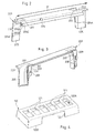
- this connecting accessory 200 comprises a flat beam 201 defined between two longitudinal edges 202, 203 parallel.
- This beam 201 carries, along a longitudinal edge 202, means cover mounting 204 which extend over a distance substantially identical to said determined length D of the transverse opening 15 provided in the longitudinal side wing 12 of the base 10.
- This beam 201 is able to be positioned in the opening transverse 15 of the longitudinal lateral flange 12 of the base 10 so that the lid mounting means 204 that it carries extend over said determined length D of this transverse opening 15 and establish a connection between the lid mounting means 14 interrupted wing lateral longitudinal 12 of the base 10 (see Figure 5).
- cover mounting means 204 bordering the beam 201 are substantially identical to the lid mounting means 14 bordering the wing lateral longitudinal 12 corresponding to the base 10.
- This snap groove is defined between two bands parallel longitudinal members 204A, 204C attached to one another by a spacer longitudinal 204B forming the bottom of said latching groove 204.
- One of the two parallel longitudinal strips is a re-entrant wall 204A attached to the longitudinal free edge 13 of the longitudinal side wing 12 corresponding to the base 10, the other of the two parallel longitudinal strips, attached to the longitudinal spacer 204B, constitutes a clipping band or latch 204C for snapping or clipping the cover of closure 20 of the base 10.
- the beam 201 of the connecting accessory 200 presents a length D greater than said determined length D so that said beam 201 has, at each end, an overflowing portion which is supported on the return 12A provided at the head of said longitudinal lateral flange 12 of the base, by covering it (see Figure 5).
- the protruding parts of the beam 201 make it possible to stabilize the connecting accessory 200 attached to the housing 100 in position on the lateral wing longitudinal 12 of the base 10.
- the connecting accessory 200 further comprises two legs 205 integral with the two end portions of the beam 201.
- jambs 205 are essentially planes, and they extend from the longitudinal edge 203 of the beam 201, opposite to that along which run said lid mounting means 204, perpendicular to said beam 201 to form with it a U-shaped arch.
- the distance separating the two legs 205 from the connecting accessory 200 is slightly smaller than the determined length D of the opening transverse 15 of the longitudinal lateral flange 12 of the base 10.
- the legs 205 of the accessory of link 200 extend on either side of said mounting means of cover 204, perpendicular to the beam 201.
- jambs 205 have a width such that, when setting placing said arch in said transverse opening 15 of said lateral wing longitudinal 12 of the base 10, they are able to cover two cut edges parallel 15A of said longitudinal lateral flange 12, bordering said opening transverse 15, as well as a part of the outer face of the latter. Thanks to their width, the jambs allow a fast cut, so unkempt, of the longitudinal side wing of the base of the chute.
- each leg 205 of the connecting accessory 200 includes, in its width, a precut line 205A allowing its cutting into to adapt the height of said leg 205A to a base of thickness or depth less than that of the base 10 shown in the figures. In that case, the space formed between the cover of the housing and the connecting accessory is closed by a wedge.
- the legs 205 and said beam 201 form a single piece made for example of molded plastic material.
- the connecting accessory 200 comprises, from the longitudinal edge 203 of the beam 201, an advance 206 in the shape of an arch.
- the connecting accessory 200 thus forms an awning which extends to counting the housing 100, in correspondence with its opening 122, in the direction of the base 10 to close the space formed between said opening 122 of the housing 100 and said transverse opening 15 of the longitudinal lateral flange 12 of the base 10.
- the connecting accessory 200 is reported on the housing 100.
- the connecting accessory comes from training with a part housing, for example that it comes from the hood by forming a projection on a side wall thereof.
- the mounting of the connecting accessory 200 on the housing 100 is made by sliding a rib in a groove.
- the connecting accessory 200 comprises at this effect, on the one hand, on the outer face 207 of its projection 206, opposite face at the lid mounting means 204, two groove means 208 arranged face to face, each on a branch of the ark, and, on the other hand, withdrawal relative to the groove means 208, two ribs 209, one behind each groove means 208, which extends parallel to the jambs 205 each forming a lateral projection on the edges of the branches of the advanced 206 in the shape of an arch.
- the plate 110 of the housing 100 for its part, for assembly purposes of the connecting accessory 200, two pairs of columns 115 which rise perpendicular to the plate 110.
- the two pairs of columns are spaced from each other by a distance substantially identical to that separating the legs 205 of the connecting accessory 200.
- a column 115 of each pair bears on an edge a rib 115A facing the other column 115 of said pair.
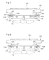
- the mounting of the connecting accessory 200 on the plate 110 is made by sliding each rib 115A of each column 115 in each corresponding groove means 208 of the connecting accessory 200, and by sliding each rib 209 of the linkage accessory 200 in each groove means 115B of each other corresponding column 115 of the plate 110.
- This arrangement makes it possible to wedge the connecting accessory 200 on the plate 110 while permitting a height adjustment thereof relative to said platinum. It facilitates a possible intervention on the cabling of the equipment for which it is necessary simply to disassemble the cover 120 and the accessory link 200.
- the connecting accessory 200 comprises, on the one hand, on one side facing the housing, on each of the branches of the arch, ribs T 208 'which extend in height parallel to the jambs 205, and, secondly, recessed from each rib T 208 ', two ribs 209 identical to those previously described.
- These columns 115 ' are hollow and define internally grooves in which are intended to slide the ribs 208 '.
- each column 115 there is also provided means for groove 115B also rising perpendicular to the plate 110 and located on the peripheral edge of the plate 110 to slidably accommodate the corresponding ribs 209 provided on the connecting accessory 200.
- the installer can choose to first report the connection accessory 200 on the plate 110 of the housing 100 before positioning said housing along the longitudinal side wing 12 corresponding, at the transverse opening 15.
- the beam 201 of the connecting accessory 200 bears on the head 12A of the lateral wing 12 of the base 10, and the cover mounting means 204 by this beam 201 extend between the two cut ends 15A means interrupted mounting 14 of said longitudinal lateral flange 12 of the base 10.
- the installer can choose to first report the connecting accessory 200 on the base 10 of the chute, before positioning the housing 100, placing the beam 201 of the connecting accessory on the head 12A of the longitudinal lateral wing 12 corresponding to the base 10 so that the mounting means of 204 cover it carries are positioned in the transverse opening 15 end end with the 14 interrupted mounting means of this wing. Then he relates the connecting accessory 200 by sliding on the plate 110 of the housing 100 positioned along the base 10 of the chute.
- the connecting accessory 200 serves as a guide and reference for the positioning of the housing 100 outside the base 10 along this one.
Landscapes
- Engineering & Computer Science (AREA)
- Architecture (AREA)
- Civil Engineering (AREA)
- Structural Engineering (AREA)
- Casings For Electric Apparatus (AREA)
- Connection Or Junction Boxes (AREA)
Abstract
Description
- la poutre déborde de part et d'autre desdits moyens de montage de couvercle de sorte qu'elle présente, à chaque extrémité, une partie qui prend appui sur la tête de ladite aile latérale longitudinale du socle, en la couvrant ;
- l'accessoire de liaison comporte deux jambages solidaires de deux parties d'extrémité de la poutre et s'étendant perpendiculairement à celle-ci pour former avec ladite poutre une arche en U, lesdits jambages présentant une largeur telle que, lors de la mise en place de ladite arche dans ladite ouverture transversale de ladite aile latérale longitudinale, ils sont aptes à recouvrir deux bords coupés parallèles de cette dernière ;
- lesdits jambages et ladite poutre forment une pièce monobloc ;
- lesdits jambages sont rapportés sur ladite poutre ;
- lesdits jambages étant essentiellement plans, ils s'étendent à partir d'un bord longitudinal de la poutre, opposé à celui le long duquel courent les moyens de montage de couvercle, et sont aptes à recouvrir une partie de la face externe de ladite aile latérale longitudinale lors de la mise en place dudit accessoire de liaison sur ledit socle ;
- l'accessoire de liaison est rapporté sur ledit boítier ;
- le montage de l'accessoire de liaison sur le boítier est réalisé par coulissement d'une nervure dans une rainure ;
- l'accessoire de liaison vient de formation avec une partie du boítier ;
- l'accessoire de liaison forme un auvent qui, s'étendant à compter du boítier, en correspondance avec son ouverture, est destiné à fermer l'espace situé entre ladite ouverture du boítier et ladite ouverture transversale de l'aile latérale longitudinale dudit socle pour établir la jonction entre l'intérieur du boítier et l'espace intérieur du socle ;
- lesdits moyens de montage de couvercle portés par ladite poutre comprennent une gorge d'encliquetage ;
- lesdits moyens de montage de couvercle portés par ladite poutre sont identiques aux moyens de montage de couvercle portés par ladite aile latérale longitudinale ; et
- l'accessoire de liaison est réalisé en une seule pièce par moulage d'une matière plastique.
- la figure 1 est une vue schématique en perspective éclatée d'un boítier pour appareillage électrique selon l'invention disposé le long d'une goulotte ;
- la figure 2 est une vue schématique en perspective d'un côté de l'accessoire de liaison du boítier de la figure 1 ;
- la figure 3 est une vue schématique en perspective d'un autre côté de l'accessoire de liaison de la figure 2 ;
- la figure 4 est une vue schématique en perspective d'une partie formant couvercle du boítier de la figure 1 ;
- les figures 5 et 6 représentent schématiquement deux étapes de montage du boítier de la figure 1, le long d'une goulotte ;
- la figure 7 est une vue de dessus d'une partie d'un mode de réalisation du boítier selon l'invention permettant de visualiser les moyens de montage de l'accessoire de liaison sur le boítier ; et
- la figure 8 est une vue de dessus d'une partie d'un autre mode de réalisation du boítier selon l'invention permettant de visualiser les moyens de montage de l'accessoire de liaison sur le boítier.
Claims (13)
- Boítier (100) pour appareillage électrique à disposer, en saillie sur une paroi, le long d'une aile latérale longitudinale (12) d'un socle (10) qui porte, le long de son bord libre longitudinal (13), des moyens de montage de couvercle (14) et qui est pourvue d'au moins une ouverture transversale (15) engendrant une interruption desdits moyens de montage de couvercle (14) sur une longueur déterminée (D), ledit boítier (100) comprenant, d'une part, dans un de ses côtés (120B), une ouverture (122) apte à venir se positionner en regard de ladite ouverture transversale (15) de ladite aile latérale longitudinale (12), et, d'autre part, un accessoire de liaison (200) qui, s'étendant à compter dudit boítier, en correspondance avec son ouverture (122), est destiné à coopérer avec ledit socle (10), caractérisé en ce que ledit accessoire de liaison (200) comprend une poutre (201) qui porte, le long d'un bord longitudinal (202), des moyens de montage de couvercle (204) aptes à s'étendre sur ladite longueur déterminée pour établir une liaison entre lesdits moyens de montage de couvercle (14) interrompus de ladite aile latérale longitudinale (12) dudit socle (10).
- Boítier (100) selon la revendication 1, caractérisé en ce que la poutre (201) déborde de part et d'autre desdits moyens de montage de couvercle (204) de sorte qu'elle présente, à chaque extrémité, une partie qui prend appui sur la tête (12A) de ladite aile latérale longitudinale (12) du socle (10), en la couvrant.
- Boítier (100) selon l'une des revendications 1 ou 2, caractérisé en ce que l'accessoire de liaison (200) comporte deux jambages (205) solidaires de deux parties d'extrémité de la poutre (201) et s'étendant perpendiculairement à celle-ci pour former avec ladite poutre une arche en U, lesdits jambages (205) présentant une largeur telle que, lors de la mise en place de ladite arche dans ladite ouverture transversale (15) de ladite aile latérale longitudinale (12), ils sont aptes à recouvrir deux bords coupés parallèles de cette dernière.
- Boítier (100) selon la revendication 3, caractérisé en ce que lesdits jambages et ladite poutre (201) forment une pièce monobloc.
- Boítier selon la revendication 3, caractérisé en ce que lesdits jambages sont rapportés sur ladite poutre.
- Boítier (100) selon l'une des revendications 3 à 5, caractérisé en ce que, lesdits jambages (205) étant essentiellement plans, ils s'étendent à partir d'un bord longitudinal (203) de la poutre (201), opposé à celui le long duquel courent les moyens de montage de couvercle (204), et sont aptes à recouvrir une partie de la face externe de ladite aile latérale longitudinale (12) lors de la mise en place dudit accessoire de liaison (200) sur ledit socle (10)
- Boítier (100) selon l'une des revendications 1 à 6, caractérisé en ce que l'accessoire de liaison (200) est rapporté sur ledit boítier.
- Boítier (100) selon la revendication 7, caractérisé en ce que le montage de l'accessoire de liaison (200) sur le boítier est réalisé par coulissement d'une nervure dans une rainure.
- Boítier selon l'une des revendications 1 à 6, caractérisé en ce que l'accessoire de liaison vient de formation avec une partie du boítier.
- Boítier (100) selon l'une des revendications 1 à 9, caractérisé en ce que l'accessoire de liaison (200) forme un auvent qui, s'étendant à compter du boítier, en correspondance avec son ouverture (122), est destiné à fermer l'espace situé entre ladite ouverture (122) du boítier (100) et ladite ouverture transversale (15) de l'aile latérale longitudinale (12) dudit socle (10) pour établir la jonction entre l'intérieur du boítier et l'espace intérieur du socle.
- Boítier (100) selon l'une des revendications 1 à 10, caractérisé en ce que lesdits moyens de montage de couvercle (204) portés par ladite poutre (201) comprennent une gorge d'encliquetage.
- Boítier (100) selon l'une des revendications 1 à 11, caractérisé en ce que lesdits moyens de montage de couvercle (204) portés par ladite poutre (201) sont identiques aux moyens de montage de couvercle (14) portés par ladite aile latérale longitudinale (12).
- Boítier (100) selon l'une des revendications précédentes, caractérisé en ce que l'accessoire de liaison (200) est réalisé en une seule pièce par moulage d'une matière plastique.
Applications Claiming Priority (2)
| Application Number | Priority Date | Filing Date | Title |
|---|---|---|---|
| FR0209518A FR2842957B1 (fr) | 2002-07-26 | 2002-07-26 | Boitier pour appareillage electrique a rapporter le long d'une goulotte |
| FR0209518 | 2002-07-26 |
Publications (2)
| Publication Number | Publication Date |
|---|---|
| EP1385244A1 true EP1385244A1 (fr) | 2004-01-28 |
| EP1385244B1 EP1385244B1 (fr) | 2012-09-26 |
Family
ID=29797674
Family Applications (1)
| Application Number | Title | Priority Date | Filing Date |
|---|---|---|---|
| EP20030291847 Expired - Lifetime EP1385244B1 (fr) | 2002-07-26 | 2003-07-25 | Boîtier pour appareillage électrique à rapporter le long d'une goulotte |
Country Status (3)
| Country | Link |
|---|---|
| EP (1) | EP1385244B1 (fr) |
| ES (1) | ES2396056T3 (fr) |
| FR (1) | FR2842957B1 (fr) |
Cited By (1)
| Publication number | Priority date | Publication date | Assignee | Title |
|---|---|---|---|---|
| AU2013205908B2 (en) * | 2012-04-04 | 2016-06-16 | Ltj Innovations Pty Ltd | Backing plate and electrical switch housing for use with C purlins, Z purlins and the like |
Citations (2)
| Publication number | Priority date | Publication date | Assignee | Title |
|---|---|---|---|---|
| US5861576A (en) * | 1996-05-08 | 1999-01-19 | Mono-Systems, Inc. | Cable raceway cable exit box |
| EP0921617A1 (fr) * | 1997-12-03 | 1999-06-09 | Legrand | Support pour appareillage à disposer le long d'une goulotte |
-
2002
- 2002-07-26 FR FR0209518A patent/FR2842957B1/fr not_active Expired - Lifetime
-
2003
- 2003-07-25 ES ES03291847T patent/ES2396056T3/es not_active Expired - Lifetime
- 2003-07-25 EP EP20030291847 patent/EP1385244B1/fr not_active Expired - Lifetime
Patent Citations (2)
| Publication number | Priority date | Publication date | Assignee | Title |
|---|---|---|---|---|
| US5861576A (en) * | 1996-05-08 | 1999-01-19 | Mono-Systems, Inc. | Cable raceway cable exit box |
| EP0921617A1 (fr) * | 1997-12-03 | 1999-06-09 | Legrand | Support pour appareillage à disposer le long d'une goulotte |
Cited By (1)
| Publication number | Priority date | Publication date | Assignee | Title |
|---|---|---|---|---|
| AU2013205908B2 (en) * | 2012-04-04 | 2016-06-16 | Ltj Innovations Pty Ltd | Backing plate and electrical switch housing for use with C purlins, Z purlins and the like |
Also Published As
| Publication number | Publication date |
|---|---|
| FR2842957A1 (fr) | 2004-01-30 |
| ES2396056T3 (es) | 2013-02-18 |
| FR2842957B1 (fr) | 2004-10-15 |
| EP1385244B1 (fr) | 2012-09-26 |
Similar Documents
| Publication | Publication Date | Title |
|---|---|---|
| FR3000310A1 (fr) | Module d'appareillage electrique | |
| EP1071183B1 (fr) | Support d'appareillage électrique à rapporter sur une goulotte | |
| EP2383849B1 (fr) | Dispositif de raccordement électrique vertical | |
| EP1385244B1 (fr) | Boîtier pour appareillage électrique à rapporter le long d'une goulotte | |
| EP1137142B1 (fr) | Boîtier pour appareillage à disposer le long d'une goulotte, notamment pour appareillage électrique | |
| EP1094579B1 (fr) | Support pour le montage d'au moins un appareillage électrique sur une goulotte pour câbles et/ou conducteurs | |
| EP1005127B1 (fr) | Support pour appareillage à disposer le long d'une goulotte avec auvent en plusieurs parties | |
| EP3840151A1 (fr) | Boite électrique et appareillage électrique associé | |
| EP1139535A1 (fr) | Accessoire à rapporter sur un socle de goulotte de cheminement de conducteurs ou de câbles électriques. | |
| EP0593362B1 (fr) | Ensemble profilé pour le câblage d'appareillages électriques dans une paroi, et ossature et goulotte propres à la constitution d'un tel ensemble profilé | |
| EP1139537B1 (fr) | Boîtier pour appareillage à disposer le long d'une goulotte, notamment pour appareillage électrique | |
| EP1164676A1 (fr) | Dispositif de montage d'un appareil électrique sur un conduit de câblage | |
| EP1304784B1 (fr) | Boitier à disposer à coté d'une goulotte de cheminement de cables ou de conducteurs électriques | |
| EP0473482B1 (fr) | Boîte de montage pour appareil électrique | |
| EP0964494B1 (fr) | Accessoire de dérivation pour installation électrique, et installation électrique correspondante | |
| FR2730869A1 (fr) | Equipement modulaire pour la fixation, le cablage et la protection d'appareillages electriques | |
| EP0848470B1 (fr) | Goulotte de distribution électrique et utilisation d'une telle goulotte | |
| EP0964495B1 (fr) | Boîte d'encastrement à corps de boîte et pied prolongeant latéralement le corps de boîte, notamment pour appareil électrique | |
| EP1351359A1 (fr) | Support d'appareillage pour goulotte avec accès aux bornes de connexion électrique | |
| FR2937986A1 (fr) | Structure comportant une premiere et une seconde parois sensiblement verticales, ecartees l'une de l'autre | |
| EP1403993B1 (fr) | Profilé à positionner à l'intérieur d'une cloison, muni de moyens de solidarisation à un rail de structure | |
| FR2910952A1 (fr) | Gaine technique | |
| EP2273636A1 (fr) | Accessoire de prolongement d'un tronçon de goulotte | |
| FR2727579A1 (fr) | Boitier de dalle pour raccordement d'equipements telephoniques et/ou informatiques et/ou electriques | |
| EP1263105A1 (fr) | Dispositif d'angle plat ou de dérivation pour goulottes |
Legal Events
| Date | Code | Title | Description |
|---|---|---|---|
| PUAI | Public reference made under article 153(3) epc to a published international application that has entered the european phase |
Free format text: ORIGINAL CODE: 0009012 |
|
| AK | Designated contracting states |
Kind code of ref document: A1 Designated state(s): AT BE BG CH CY CZ DE DK EE ES FI FR GB GR HU IE IT LI LU MC NL PT RO SE SI SK TR |
|
| AX | Request for extension of the european patent |
Extension state: AL LT LV MK |
|
| 17P | Request for examination filed |
Effective date: 20040331 |
|
| AKX | Designation fees paid |
Designated state(s): DE ES IT PT TR |
|
| RAP1 | Party data changed (applicant data changed or rights of an application transferred) |
Owner name: LEGRAND FRANCE |
|
| RAP1 | Party data changed (applicant data changed or rights of an application transferred) |
Owner name: LEGRAND FRANCE Owner name: LEGRAND SNC |
|
| GRAP | Despatch of communication of intention to grant a patent |
Free format text: ORIGINAL CODE: EPIDOSNIGR1 |
|
| GRAS | Grant fee paid |
Free format text: ORIGINAL CODE: EPIDOSNIGR3 |
|
| GRAA | (expected) grant |
Free format text: ORIGINAL CODE: 0009210 |
|
| AK | Designated contracting states |
Kind code of ref document: B1 Designated state(s): DE ES IT PT TR |
|
| REG | Reference to a national code |
Ref country code: DE Ref legal event code: R096 Ref document number: 60342176 Country of ref document: DE Effective date: 20121122 |
|
| REG | Reference to a national code |
Ref country code: ES Ref legal event code: FG2A Ref document number: 2396056 Country of ref document: ES Kind code of ref document: T3 Effective date: 20130218 |
|
| PG25 | Lapsed in a contracting state [announced via postgrant information from national office to epo] |
Ref country code: PT Free format text: LAPSE BECAUSE OF FAILURE TO SUBMIT A TRANSLATION OF THE DESCRIPTION OR TO PAY THE FEE WITHIN THE PRESCRIBED TIME-LIMIT Effective date: 20130128 |
|
| PLBE | No opposition filed within time limit |
Free format text: ORIGINAL CODE: 0009261 |
|
| STAA | Information on the status of an ep patent application or granted ep patent |
Free format text: STATUS: NO OPPOSITION FILED WITHIN TIME LIMIT |
|
| 26N | No opposition filed |
Effective date: 20130627 |
|
| REG | Reference to a national code |
Ref country code: DE Ref legal event code: R097 Ref document number: 60342176 Country of ref document: DE Effective date: 20130627 |
|
| PGFP | Annual fee paid to national office [announced via postgrant information from national office to epo] |
Ref country code: DE Payment date: 20170727 Year of fee payment: 15 |
|
| REG | Reference to a national code |
Ref country code: DE Ref legal event code: R119 Ref document number: 60342176 Country of ref document: DE |
|
| PG25 | Lapsed in a contracting state [announced via postgrant information from national office to epo] |
Ref country code: DE Free format text: LAPSE BECAUSE OF NON-PAYMENT OF DUE FEES Effective date: 20190201 |
|
| PGFP | Annual fee paid to national office [announced via postgrant information from national office to epo] |
Ref country code: IT Payment date: 20190723 Year of fee payment: 17 Ref country code: ES Payment date: 20190809 Year of fee payment: 17 Ref country code: TR Payment date: 20190717 Year of fee payment: 17 |
|
| PG25 | Lapsed in a contracting state [announced via postgrant information from national office to epo] |
Ref country code: IT Free format text: LAPSE BECAUSE OF NON-PAYMENT OF DUE FEES Effective date: 20200725 |
|
| REG | Reference to a national code |
Ref country code: ES Ref legal event code: FD2A Effective date: 20211203 |
|
| PG25 | Lapsed in a contracting state [announced via postgrant information from national office to epo] |
Ref country code: ES Free format text: LAPSE BECAUSE OF NON-PAYMENT OF DUE FEES Effective date: 20200726 |
|
| PG25 | Lapsed in a contracting state [announced via postgrant information from national office to epo] |
Ref country code: TR Free format text: LAPSE BECAUSE OF NON-PAYMENT OF DUE FEES Effective date: 20200725 |