EP1384980A1 - Moisture protection for an electromechanical transducer - Google Patents
Moisture protection for an electromechanical transducer Download PDFInfo
- Publication number
- EP1384980A1 EP1384980A1 EP02102061A EP02102061A EP1384980A1 EP 1384980 A1 EP1384980 A1 EP 1384980A1 EP 02102061 A EP02102061 A EP 02102061A EP 02102061 A EP02102061 A EP 02102061A EP 1384980 A1 EP1384980 A1 EP 1384980A1
- Authority
- EP
- European Patent Office
- Prior art keywords
- layer
- strain gauge
- polymer
- multilayer
- vapor deposition
- Prior art date
- Legal status (The legal status is an assumption and is not a legal conclusion. Google has not performed a legal analysis and makes no representation as to the accuracy of the status listed.)
- Withdrawn
Links
Images
Classifications
-
- G—PHYSICS
- G01—MEASURING; TESTING
- G01G—WEIGHING
- G01G3/00—Weighing apparatus characterised by the use of elastically-deformable members, e.g. spring balances
- G01G3/12—Weighing apparatus characterised by the use of elastically-deformable members, e.g. spring balances wherein the weighing element is in the form of a solid body stressed by pressure or tension during weighing
- G01G3/14—Weighing apparatus characterised by the use of elastically-deformable members, e.g. spring balances wherein the weighing element is in the form of a solid body stressed by pressure or tension during weighing measuring variations of electrical resistance
- G01G3/1402—Special supports with preselected places to mount the resistance strain gauges; Mounting of supports
- G01G3/1412—Special supports with preselected places to mount the resistance strain gauges; Mounting of supports the supports being parallelogram shaped
-
- G—PHYSICS
- G01—MEASURING; TESTING
- G01B—MEASURING LENGTH, THICKNESS OR SIMILAR LINEAR DIMENSIONS; MEASURING ANGLES; MEASURING AREAS; MEASURING IRREGULARITIES OF SURFACES OR CONTOURS
- G01B7/00—Measuring arrangements characterised by the use of electric or magnetic techniques
- G01B7/16—Measuring arrangements characterised by the use of electric or magnetic techniques for measuring the deformation in a solid, e.g. by resistance strain gauge
- G01B7/18—Measuring arrangements characterised by the use of electric or magnetic techniques for measuring the deformation in a solid, e.g. by resistance strain gauge using change in resistance
-
- G—PHYSICS
- G01—MEASURING; TESTING
- G01G—WEIGHING
- G01G21/00—Details of weighing apparatus
-
- G—PHYSICS
- G01—MEASURING; TESTING
- G01L—MEASURING FORCE, STRESS, TORQUE, WORK, MECHANICAL POWER, MECHANICAL EFFICIENCY, OR FLUID PRESSURE
- G01L1/00—Measuring force or stress, in general
- G01L1/20—Measuring force or stress, in general by measuring variations in ohmic resistance of solid materials or of electrically-conductive fluids; by making use of electrokinetic cells, i.e. liquid-containing cells wherein an electrical potential is produced or varied upon the application of stress
- G01L1/22—Measuring force or stress, in general by measuring variations in ohmic resistance of solid materials or of electrically-conductive fluids; by making use of electrokinetic cells, i.e. liquid-containing cells wherein an electrical potential is produced or varied upon the application of stress using resistance strain gauges
- G01L1/2287—Measuring force or stress, in general by measuring variations in ohmic resistance of solid materials or of electrically-conductive fluids; by making use of electrokinetic cells, i.e. liquid-containing cells wherein an electrical potential is produced or varied upon the application of stress using resistance strain gauges constructional details of the strain gauges
Definitions
- the invention relates to a load cell with a deformation body and with at least one strain gauge applied to the deformation body, which is a strain sensitive electrical applied to a support Resistance path and connection electrodes for contacting the resistance path has, the at least one strain gauge and optionally at least part of the deformation body is provided with a multilayer layer, as well as a single strain gauge or a row or surface arrangement of strain gauges, provided with a strain sensitive on a support applied electrical resistance track, with a the resistance track and at least part of the multilayer layer covering the carrier. Furthermore, the Invention a method for producing a multilayer on a Strain gauges, or a row or surface arrangement of strain gauges, or on a load cell with a strain gauge.
- a strain gauge has a metallic one attached to a carrier Resistance path, which is preferably in the form of a meandering structure known etching process is produced. Furthermore are on the carrier Connection electrodes for contacting the resistance path available, this often arise in one operation with the resistance track and thus mostly out consist of the same material.
- a carrier material for strain gauges electrical insulators used; depending on the area of application, you will find glass, Ceramics, often also polymers, glass fiber reinforced polymers or Composite materials. Strain gauges are measuring elements in which one mechanical deformation causes a change in the electrical resistance, and which are therefore used to measure the force causing the deformation.
- strain gauges are changing a deformation caused by a force on a deformation body in a electrical signal used.
- One is created in such a load cell Deflection of the vertically movable load receiver in relation to the spatial fixed part of the deformation body by the force of a load on the weighing pan connected to the load receiver.
- Such deformation bodies have four forms of formation due to thin material areas shaped, elastic bending points, each at the four corner points Parallelograms are arranged, the load receiver being vertically movable Parallelogram leg compared to one preferably on the scale housing attached, also vertical parallelogram leg is arranged.
- the size of the deformation caused in the thin bending points is at least one on one of the bending points, usually by means of an electrically insulating one Strain gauge applied as a change in its electrical layer Resistance measured.
- polymeric carrier materials especially polyimides, but also epoxies, Phenolic resins, melamines and ketones used for strain gauges.
- polymers Beams have the advantage that they are due to their lower rigidity Adjust deformation body better. In particular, the mechanical Reduced stress on the adhesive layer. Hysteresis effects or destruction of some rigid supports with an adhesive layer connecting the deformation body occur here far less.
- polymeric carrier materials enable Strain gauges with a meandering resistance track As is known, load drift compensation through appropriate training the reversal points of the resistance track.
- strain gauges are included polymer carriers easier to handle and cheaper to manufacture.
- polymers have the disadvantage that they have a relatively high absorption capacity for water, but also for solvents, so that the moisture content the air surrounding a load cell, but especially its changes, has a lasting influence on the measurement result.
- the Sensitivity, the stability of the zero point and the creep behavior, the so-called Load drift which is influenced by moisture - with regard to water and solvents Parameters of a load cell with a strain gauge as a transducer.
- the backing takes an unprotected one Strain gauge the moisture and swells, so that the The distance between the resistance track and the bending point is increased, and thus that of the deforming bending point in the resistance path induced deformation is changed slightly.
- absorbed moisture changes the elastic properties of the carrier material and thus the deformation parameters the resistance track.
- an increased moisture content of the carrier material Leakage currents between adjacent areas of a meandering shape Resistance track, or even between the resistance track and the metallic one causes deformation body.
- a protective measure against moisture is known from US Pat. No. 5,631,622 Strain gauges known in the subsequent to their manufacture in a Surface arrangement, before separating the strain gauges, first one electrically insulating polymer layer is applied to the strain gauges and a metal foil is laminated on it as an additional cover. Even after the Separation is a strain gauge against a large area through the metal foil Protected against moisture.
- JP-A-7 113 697 proposes that, in order to prevent the penetration of moisture, a thin inorganic film, for example SiO 2, with a thickness of about 100 nanometers (nm) , as it were applied as a moisture barrier layer on the surface of the strain gauge.
- An inorganic insulation film, for example polyimide, with a thickness of about 10 micrometers ( ⁇ m) is then applied, by means of which microscopic holes or cracks in the inorganic film, so-called pinholes, through which moisture could continue to penetrate, become blocked.
- the protective effect produced by this two-layer layer is not always satisfactory, especially in the case of the highly sensitive load cells designed for relatively low loads.
- DE-40 15 666 C2 discloses a strain gauge Force transducer, a strain gauge and the adjacent part of the Carrier with a vapor-deposited, diffusion-tight, electrically insulating Coating of silicon oxide or silicon carbide is provided, the layer thickness is preferably two to four micrometers.
- the coating can also consist of a lower silicon oxide layer and a layer above it located metal layer, preferably a nickel layer.
- Metal layers or foils bear due to their comparatively high rigidity from a thickness of just a few micrometers ( ⁇ m) to a measurable one Force shunt at.
- a force shunt occurs, for example in that thick inorganic protective layers because of their high rigidity significant to the overall rigidity of the bending points of the Contribute deformation body. Smaller in the case of load cells Forces this is particularly problematic because here the bends to achieve one high sensitivity only have a small thickness. That means unwanted Changes in the elastic properties of the protective layer, such as anelastic aftereffect, high inelasticity, especially strain hysteresis, lead to a non-reproducible and therefore not software-related compensable measurement error.
- the invention takes advantage of the excellent barrier properties that the predominantly have inorganic materials, and reduced by the Use of very thin barrier layers which have a very high stiffness thick inorganic layers which are used in the prior art. This is done by a multiple coating from an alternating sequence of thin barrier layers and thin polymer layers. Polymer layers though show only a moderate barrier effect, and therefore often none by itself can offer sufficient moisture protection, but a significantly lower one Stiffness are suitable, along with thin, predominantly inorganic barrier layers of the multilayer layer overall a low To give stiffness. In this way, those mentioned at the outset remain with the low rigidity associated advantages of a polymeric carrier material for a Strain gauge received. Due to very thin barrier layers within the Multi-layer layer becomes the danger of the force shunt described above largely avoided.
- the aforementioned pinholes firstly ensure a certain degree of sealing and secondly they pinholes of two "adjacent" barrier layers are spatially offset, and prevents the ingress of moisture at such weak points in the form of a Labyrinths for the water and solvent molecules.
- an efficient moisture protection can be achieved without that Measurement result is impaired.
- the invention provides another, with thick inorganic barrier layers eliminates the associated disadvantage, namely the risk of the layer becoming detached, the so-called delamination.
- This delamination is caused by the fact that high rigidity of a comparatively thick barrier layer the transition from the Surface of the strain gauge to the barrier layer considerable mechanical Exposed to tension.
- the use of thin according to the invention Has barrier layers in an alternating sequence with thin polymer layers regarding the undesired detachment of a barrier layer from its base very high stability.
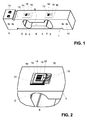
- Figure 1 shows the deformation body 1 of a load cell with four to the Corner points of a parallelogram arranged elastic bending points 2, 3, 4, 5. These are formed by edge regions 6, 7 of a recess 8 that are widened in an arc formed in the center of the one-piece deformation body 1.
- the one on the left in the figure Load receiver 9 shown of the deformation body 1 is in the vertical direction movable. Is on a weighing pan that is not visible here - by the way, by means of several screws in the threads 10 on the load sensor 9 can be fastened - one Load on, so the load sensor 9 steers while deforming the bending points 2, 3, 4 and 5 vertically downwards compared to a fixed one shown on the right in the figure Part 11 of the deformation body 1.
- the strain gauges 13 are provided with a multilayer 16 Protection against the ingress of moisture, i.e. water or solvents, provided, the structure and operation of which will be explained in detail below.
- the multilayer 16 is here drawn transparently. However, there is no need for the Multi-layer layers 16 are transparent to light in their real form.
- the multilayer 16 has been applied directly to the strain gauge 13 already connected to the deformation element 1, for example by vapor deposition.
- the epoxy resin frequently used as an adhesive material which was used here to stick the strain gauge onto the deformation body and which extends somewhat beyond the surface edge of the strain gauge, is also covered (see FIG. 2). This means that moisture-related influences of the adhesive material on the weighing result are also prevented.
- the value for the permeation of water or solvents in the case of an uncoated strain gauge, which is applied to a polyimide carrier that has already been optimized with regard to moisture absorption is one gram per square meter and day (1 g / m 2 / d ), under the conditions of a difference in ambient humidity of 90% RH and a temperature of 23 ° C.
- This value is reduced by several orders of magnitude by means of the coating of the strain gauge according to the invention, so that the above-mentioned parameters of a load cell experience a corresponding rate of change.
- the coating described is already on the deformation body a strain gauge applied to a load cell is preferred as a particularly cost-effective coating method for vapor deposition in air Application come.
- the steam becomes a preferably substance in solution in a gas-fed flame heated up where it reacts chemically before settling on a near flame precipitated substrate.
- FIG. 2 the area of the area enclosed by the circle A in FIG Deformation body 1 shown enlarged. It is as in Figure 1 on the Bending point 2 applied strain gauges 13 with this and a part of Top 12 of the deformation body 1, in particular also the one mentioned above To see adhesive layer 21 covering multilayer 16.
- the multilayer 16 again transparent and on top of it in the figure right-hand side drawn broken. They are also Connection electrodes 17 of the meandering resistance track can be seen. This must of course also after the application of a multilayer 16 for the connection of the detecting bridge circuit (not shown here) accessible his. At the same time, however, the multilayer 16 should not have the contact Surface of the contact point may be damaged.
- Connection electrodes 17 even before coating with a drop of electrical conductive connecting material, i.e. which in the figure as an oval Drawn contact points 18 are created, the contacting process only the part of the multilayer 16 which covers the contact point 18, is opened and other areas of the multilayer 16 remain undamaged.
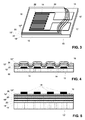
- FIG. 3 shows a three-dimensional representation of a single strain gauge 13, the one with a multilayer 16, which incidentally also for one Multilayer arrangement according to FIGS. 1 and 2 can be used, is provided.
- the multilayer 16 is again here drawn transparently and broken. It consists of a regular sequence of Polymer layers 19, preferably made of a polyacrylate or polymethacrylate, and Barrier layers 20, made of a predominantly inorganic insulator, the Polymer layers 19 typically have a thickness of 50 to 500 nm, preferably 100 nm to 200 nm, in individual cases but also going beyond one Can have layer thickness of up to 1500 nm.
- the layer thickness of the Barrier layers 20 are typically between 5 nm and 200 nm, preferably between 10 nm and 50 nm, can also be up to 500 nm in individual cases.
- FIG. 4 shows a section through a strain gauge 13 with one of a total of five thin individual layers shows existing applied multilayer 16.
- the drawing is highly schematic and it is the respective thickness of the carrier 15, the Resistance track 14 and the barrier layers 20 and the polymer layers 19 ', 19 ", 19" 'not drawn to scale here.
- first layer 19 'of multilayer 16 is preferably an acrylate polymer layer, which serves for roughness of the beam 15 and the resistance track 14 smooth. It may have a greater thickness than that further polymeric intermediate layers 19 "of the multilayer 16. With such Acrylate polymer layers can reduce the roughness of a substrate in the nanometer range be leveled out. In this way, the formation of a low-defect following barrier layer 20 favors, that is, the emergence of pinholes reduced in the first barrier layer 20 by the smoothing effect of its base becomes.
- a named polymer layer fulfills this requirement on the one hand leveling properties on the nanometer scale and on the other Conformal micrometer scale, that is also predominantly perpendicular to Layer-covering surfaces covering properties. So she creates that Prerequisite for the formation of uniformly thick and poor defects Barrier layers 20 and subsequent layers of the multilayer 16.
- a polymeric intermediate layer follows the first barrier layer 20. Your function is in addition to stabilizing the first barrier layer 20, also reducing the Formation of pinholes in a further layer 19 "following the intermediate layer Barrier layer 20 due to its smoothing effect.
- the Intermediate layer 19 "avoided that a small number were created Pinholes of a second barrier layer 20 adhere to those of the first barrier layer 20 fix, which would favor the passage of moisture again.
- the multilayer 16 shown in FIG. 4 has five thin individual layers, of which the first layer is the leveling polymer layer 19 'and that A layer forming the boundary layer with the ambient atmosphere Polymer layer 19 "'is to the multilayer 16 especially against mechanical Stabilize damage.
- the multi-layer layer 16 can still more Have individual layers; the sequence of polymer layer 19 and barrier layer 20 can in principle be repeated any number of times.
- the multilayer 16 can also consist of a total of only three thin individual layers, preferably of a sequence of polymer layer 19 '- barrier layer 20 - polymer layer 19 "'.
- inorganic Insulators can be used. Examples include oxides, nitrides, fluorides, carbides, Borides or combinations thereof, in particular oxynitrides, or also Mixed ceramics called.
- silicon oxide, titanium oxide, Chromium oxide, aluminum oxide, silicon nitride and titanium nitride as material for the Barrier layers 20 proven.
- the so-called “diamond-like carbon” layers can be used as possible barrier layers 20.
- barrier layers 20 also come Metals, for example silver, aluminum, gold, chrome, copper, nickel, titanium, and Alloys, for example nickel-cobalt alloys, or intermetallic Connections, for example made of aluminum and copper, made of tungsten and copper or made of titanium and aluminum in question.
- Metals for example silver, aluminum, gold, chrome, copper, nickel, titanium, and Alloys, for example nickel-cobalt alloys, or intermetallic Connections, for example made of aluminum and copper, made of tungsten and copper or made of titanium and aluminum in question.
- polymers can also be used for the polymer layers 19 Find materials. Examples include: polymeric amides, Alkyds, styrenes, xylylenes, phenylenes, aldehydes, esters, urethanes, epoxides, imides, Phenols, ketones as well as fluoropolymers or copolymers, the listing here cannot be final. Ultimately, optimization decides between Barrier effect, combinability of the barrier layer 20 and the polymer layer 19, and economy of the coating method using the Barrier layer material as well as the use of the polymer material.
- a thin barrier layer 20 has a corresponding one low rigidity. Therefore, in cooperation with the flexible per se Polymer layer 19 only a minimal force bypass by applying one Multi-layer layer 16 with ultra-thin barrier layers 20 on strain gauges 13 to fear. For the same reason, there is a risk of the ultrathin peeling off Barrier layers 20 from their base (delamination) massively reduced and could not observed for materials used in the invention.
- the inventive coating of strain gauges 13 with a Multi-layer layer 16 can follow the production of the strain gauges 13 as long as these are still available in a row or area arrangement.
- the side surfaces remain, especially the carrier film, open and penetrating moisture accessible. Due to the area ratio of the top and side edges of one Strain gauge is the protective effect of the inventive Multi-layer 16 is still quite high. It can be extremely efficient with this Coating method strain gauges 13 are produced, the Moisture absorption depending on the materials used by a factor 50 to 1000 is smaller compared to uncoated strain gauges.
- a barrier effect higher than the one mentioned should be achieved it is of course also possible to use individual strain gauges 13, if necessary all around to coat, whereby the side surfaces of the carrier 15, at least at careful handling.
- the individual barrier layers 20 are not within a multilayer layer 16 necessarily from the same material.
- the polymer layers are also not 19 limited to a single material.
- barrier layers 20 to build up from partial layers, be it that identical or that different materials are used. Such multiple layers with different internal structure increase the labyrinth effect. Even for individuals Polymer layers 19 ', 19 ", 19"', a composition of partial layers is conceivable. The only important thing here is that the barrier layers 20 and Polymer layers 19 are thin, i.e. their respective layer thickness in the area above mentioned values, and that the total thickness of the multilayer 16 for highly sensitive load cells, strain gauges can be applied one micron, at most, however, does not exceed ten micrometers, and therefore not a significant one Force shunt occurs.
- the respective thickness of the individual barrier layers or polymer layers within a multi-layer layer but especially its total layer thickness that also used coating materials or other Coating parameters play a role, a function of the load capacity and the required sensitivity of the strain gauges coated with such provided load cells. That is, the higher the load capacity of one Load cell, the larger the tolerable force shunt, which, as mentioned above, by a protective layer on the strain gauge can be caused. In principle, however, the principle applies, the thinner one Multilayer is, in particular, the thinner the barrier layers contained therein the better it is suitable for use as a protective layer Strain gauges.
- a coating of their Strain gauges can have their total thickness, that is the thickness of the Multilayer, up to ten microns, but preferably below five micrometers, but in particular below one micrometer lies.
- the total thickness can be used for load cells with a capacity of up to five kilograms the multilayer may be up to fifteen micrometers, but is preferably below ten micrometers, but in particular below five micrometers.
- On load cells with a capacity of over five kilograms up to about 50 Kilograms of applied strain gauges can with a multi-layer or covered with a multi-layer film in the micrometer range without the force shunt having any significant influence on the Weighing result.
- the multilayer 16 consists of an alternating sequence of one Polymer layer 19, in particular a polyacrylate or polymethacrylate layer and a barrier layer 20, preferably made of silicon oxide or aluminum oxide, is built, the due to the choice of an efficient coating process the materials used are uniform, as are the individual ones Layers are homogeneous in themselves.
- the boundary layer to the carrier 15, respectively to the resistance track 14 and the connection electrodes 17 is a polymer layer 19 ', for the boundary layer with the surrounding atmosphere, this is not absolutely necessary, although preferred, since a final polymer layer 19 "'is a good one mechanical and possibly chemical protection for a final barrier layer 20 offers. This means that, if necessary, the choice of used Polymer material for the final polymer layer 19 "'in terms of Property, a particularly good mechanical and / or chemical protection to be able to bid.
- the area of the Strain gauge 13 may also prove necessary in terms of the area of the Strain gauge 13 to apply only a partial coating to such.
- Only the meandering structure of the resistance track 14 can be coated because the penetrating moisture has the greatest effect, or the Coating is preferably carried out in the area of the reversal points 22 of the meandering structure (see Figure 3) of the resistance track 14.
- the electrical contacting of the resistance track 14 on the connection electrodes 17 to avoid these can also be left free of a coating. For this it is necessary to work with masks when coating, which are too leave coating areas free.
- the idea of the invention also includes the large-scale production of with a described multilayer 16 provided polymer films, for example Polyimide films, which are used as a carrier material for the coating Strain gauges are used, i.e. with a resistance track on the coated side.
- a strain gauge 13 ' is in the FIG. 5 is shown in a highly schematic manner, the multilayer 16 here consisting of seven There are individual layers. The application of such strain gauges 13 ', for example on the deformation body 1 of a load cell takes place in the usual way.
- the resistance path 14 is not per se before changes in the Moisture from the surrounding atmosphere is protected, but is mainly through Moisture absorption carrier 15 causing measurement errors described above largely protected, so that the moisture-related influences on the Measurement result are at least reduced.
- the application of a strain gauge 13 ', the resistance track 14 on the with the multilayer layer 16 side of the carrier 15 is applied to the Deformation body 1 of a load cell can also take place in such a way that the Resistance track 14 facing the deformation body 1 in an as electrical insulating intermediate layer acting adhesive material is embedded.
- the task of Protective layer takes over the preferably not too thick, coated carrier film the task of Protective layer and especially protects the adhesive layer 21 and the resistance track 14 before the influences of changing moisture.
- strain-dependent resistance track 14 are provided.
- a strain gauge with the resistance track 14 to the deformation body 1 facing an adhesive material with very good electrical insulating properties to apply embedded.
- carrier film with a thickness of preferably only a few micrometers.
- the deformation body 1 before applying the Strain gauges, at least in the area of the bending points, with an electrical to provide insulating cover so that the adhesive layer is not exclusive has to take over the function of electrical insulation.
- a multilayer 16, consisting of an alternating sequence of Polymer layers 19 and barrier layers 20 are also easily applied to a thin, Polymer film, for example made of a polyacrylate, polymethacrylate, polyimide, PET, Fluoropolymer or one of the inputs for use as a carrier material mentioned polymers can be applied.
- the coated film is then placed on a Strain gauge 13 laminated either with the multilayer 16 or with the thin polymer film in contact with the carrier 15 and the resistance track 14. It is advantageous here, as in the case of a coating described above Backing film that the film coating as an industrial process is very inexpensive is.
- Such a film which is designed as a multilayer, can now also have a film Strain gauge 13, which directly on a deformation body 1 one preferably designed for medium to higher load capacities is applied, be attached.
- the strain gauge is not mandatory be connected to a film as a carrier 15, but can be directly on an electrical insulating covering of the deformation body 1 can be applied, the Deformation body 1 with the electrically insulating covering, for example created by anodizing an aluminum deformation body, as a carrier for the Resistor track 14 and the connection electrodes 17 acts.
- the preferred method of making a multilayer 16 on one individual strain gauges 13 or one already on the deformation element 1 Strain gauge 13 applied to a load cell comprises the following steps: Application of a conformal polymer layer 19 'flattening in the nanometer range with a thickness between 200 nm and 1500 nm on at least one part the resistance track 14 and / or the connection electrodes 17 and / or the carrier 15 and optionally the deformation body 1, depositing an approximately 20 nm thick, barrier layer 20 on the polymer layer 19 ', deposit another thin polymer layer 19 "with a thickness of about 100 nm to 200 nm on the Barrier layer 20, repetition of the coating process as often as desired a barrier layer 20 and a polymer layer 19 ", being used as a boundary layer for Ambient atmosphere a polymer layer 19 "'or a thin barrier layer 20 can be present.
- a method for coating on the has proven to be particularly efficient Deformation body 1 of a load cell can be applied or applied Strain gauges 13, with a multilayer 16 when producing the Multi-layer 16 by alternating coating with polymer layers 19 and Barrier layers 20 within a coating apparatus by means of two sources in one operation.
Abstract
Description
Die Erfindung betrifft eine Kraftmesszelle mit einem Verformungskörper und mit mindestens einem auf dem Verformungskörper aufgebrachten Dehnmessstreifen, welcher eine dehnungsempfindliche auf einem Träger aufgebrachte elektrische Widerstandsbahn und Anschlusselektroden zur Kontaktierung der Widerstandsbahn aufweist, wobei der mindestens eine Dehnmessstreifen und gegebenenfalls mindestens ein Teil des Verformungskörpers mit einer Mehrlagenschicht versehen ist, sowie einen einzelnen Dehnmessstreifen oder eine Reihen- oder Flächenanordnung von Dehnmessstreifen, versehen mit einer dehnungsempfindlichen auf einem Träger aufgebrachten elektrischen Widerstandsbahn, mit einer die Widerstandsbahn und mindestens einen Teil des Trägers bedeckenden Mehrlagenschicht. Ferner betrifft die Erfindung ein Verfahren zur Herstellung einer Mehrlagenschicht auf einem Dehnmessstreifen, oder einer Reihen- oder Flächenanordnung von Dehnmessstreifen, beziehungsweise auf einer mit einem Dehnmessstreifen versehenen Kraftmesszelle.The invention relates to a load cell with a deformation body and with at least one strain gauge applied to the deformation body, which is a strain sensitive electrical applied to a support Resistance path and connection electrodes for contacting the resistance path has, the at least one strain gauge and optionally at least part of the deformation body is provided with a multilayer layer, as well as a single strain gauge or a row or surface arrangement of strain gauges, provided with a strain sensitive on a support applied electrical resistance track, with a the resistance track and at least part of the multilayer layer covering the carrier. Furthermore, the Invention a method for producing a multilayer on a Strain gauges, or a row or surface arrangement of strain gauges, or on a load cell with a strain gauge.
Ein Dehnmessstreifen weist eine auf einem Träger aufgebrachte metallische Widerstandsbahn auf, welche vorzugsweise in Form einer Mäanderstruktur mittels bekanntem Ätzverfahren hergestellt wird. Ferner sind auf dem Träger Anschlusselektroden zur Kontaktierung der Widerstandsbahn vorhanden, wobei diese häufig in einem Arbeitsgang mit der Widerstandsbahn entstehen und somit meist aus demselben Material bestehen. Als Trägermaterial für Dehnmessstreifen werden elektrische Isolatoren verwendet; je nach Anwendungsbereich findet man Glas, Keramik, häufig auch Polymere, glasfaserverstärkte Polymere oder Kompositmaterialien. Dehnmessstreifen sind Messelemente, bei welchen eine mechanische Verformung eine Änderung des elektrischen Widerstandes hervorruft, und welche daher zur Messung der die Verformung bewirkenden Kraft benutzt werden.A strain gauge has a metallic one attached to a carrier Resistance path, which is preferably in the form of a meandering structure known etching process is produced. Furthermore are on the carrier Connection electrodes for contacting the resistance path available, this often arise in one operation with the resistance track and thus mostly out consist of the same material. As a carrier material for strain gauges electrical insulators used; depending on the area of application, you will find glass, Ceramics, often also polymers, glass fiber reinforced polymers or Composite materials. Strain gauges are measuring elements in which one mechanical deformation causes a change in the electrical resistance, and which are therefore used to measure the force causing the deformation.
In der Wägetechnologie, beispielsweise, werden Dehnmessstreifen zur Wandlung einer durch eine Kraft auf einen Verformungskörper bewirkten Verformung in ein elektrisches Signal verwendet. In einer solchen Kraftmesszelle entsteht eine Auslenkung des vertikal beweglichen Lastaufnehmers gegenüber dem räumlich feststehenden Teil des Verformungskörpers durch die Kraftwirkung einer Last auf der mit dem Lastaufnehmer verbundenen Waagschale. In einer bevorzugten Ausbildungsform weisen solche Verformungskörper vier durch dünne Materialbereiche geformte, elastische Biegestellen auf, welche jeweils an den vier Eckpunkten eines Parallelogramms angeordnet sind, wobei der Lastaufnehmer als vertikal beweglicher Parallelogrammschenkel gegenüber einem vorzugsweise am Waagengehäuse befestigten, ebenfalls vertikalen Parallelogrammschenkel angeordnet ist. Die Grösse der in den dünnen Biegestellen hervorgerufenen Verformung wird mit mindestens einem auf einer der Biegestellen, meist mittels einer elektrisch isolierenden Klebeschicht aufgebrachten Dehnmessstreifen als Änderung seines elektrischen Widerstands gemessen.In weighing technology, for example, strain gauges are changing a deformation caused by a force on a deformation body in a electrical signal used. One is created in such a load cell Deflection of the vertically movable load receiver in relation to the spatial fixed part of the deformation body by the force of a load on the weighing pan connected to the load receiver. In a preferred one Such deformation bodies have four forms of formation due to thin material areas shaped, elastic bending points, each at the four corner points Parallelograms are arranged, the load receiver being vertically movable Parallelogram leg compared to one preferably on the scale housing attached, also vertical parallelogram leg is arranged. The size of the deformation caused in the thin bending points is at least one on one of the bending points, usually by means of an electrically insulating one Strain gauge applied as a change in its electrical layer Resistance measured.
Aufgrund ihrer elastischen Eigenschaften werden in der Wägetechnologie bevorzugt polymere Trägermaterialien, insbesondere Polyimide, aber auch Epoxide, Phenolharze, Melamine und Ketone für Dehnmessstreifen verwendet. Polymere Träger haben den Vorteil, dass sie sich aufgrund ihrer geringeren Steifigkeit dem Verformungskörper besser anpassen. Insbesondere wird dadurch die mechanische Belastung der Klebeschicht reduziert. Hystereseeffekte oder eine Zerstörung der einen starren Träger mit einem Verformungskörper verbindenden Klebeschicht treten hier weitaus weniger auf. Zusätzlich ermöglichen polymere Trägermaterialien bei Dehnmessstreifen mit einer mäanderförmig ausgebildeten Widerstandsbahn bekanntermassen eine Lastdriftkompensation durch eine entsprechende Ausbildung der Umkehrstellen der Widerstandsbahn. Im Übrigen sind Dehnmessstreifen mit polymeren Trägern besser handhabbar und preisgünstiger herzustellen.Weighing technology is preferred due to its elastic properties polymeric carrier materials, especially polyimides, but also epoxies, Phenolic resins, melamines and ketones used for strain gauges. polymers Beams have the advantage that they are due to their lower rigidity Adjust deformation body better. In particular, the mechanical Reduced stress on the adhesive layer. Hysteresis effects or destruction of some rigid supports with an adhesive layer connecting the deformation body occur here far less. In addition, polymeric carrier materials enable Strain gauges with a meandering resistance track As is known, load drift compensation through appropriate training the reversal points of the resistance track. In addition, strain gauges are included polymer carriers easier to handle and cheaper to manufacture.
Polymere besitzen jedoch den Nachteil, dass sie eine relativ hohe Aufnahmefähigkeit für Wasser, aber auch für Lösungsmittel aufweisen, so dass der Feuchtigkeitsgehalt der eine Kraftmesszelle umgebenden Luft, insbesondere aber dessen Änderungen, einen nachhaltigen Einfluss auf das Messresultat hat. Beispielsweise sind die Empfindlichkeit, die Stabilität des Nullpunkts und das Kriechverhalten, die sogenannte Lastdrift, von der Feuchtigkeit - betreffend Wasser und Lösungsmitteln - beeinflusste Parameter einer mit Dehnmessstreifen als Wandler beaufschlagten Kraftmesszelle. However, polymers have the disadvantage that they have a relatively high absorption capacity for water, but also for solvents, so that the moisture content the air surrounding a load cell, but especially its changes, has a lasting influence on the measurement result. For example, the Sensitivity, the stability of the zero point and the creep behavior, the so-called Load drift, which is influenced by moisture - with regard to water and solvents Parameters of a load cell with a strain gauge as a transducer.
Für die Grössenordnung der durch Änderung dieser Parameter verursachten Änderungen des Wägeresultats wurden einige zehn bis einige hundert parts-permillion (ppm) des Vollausschlages (Signal bei Volllast) im Falle einer stufenförmigen Änderung des Feuchtigkeitsgehalts der eine Kraftmesszelle umgebenden Luft von ca. 30% relativer Feuchtigkeit (rF) auf 85% rF im typischen Temperaturbereich zwischen 10°C und 40°C gemessen.For the order of magnitude caused by changing these parameters Changes in the weighing result were several tens to several hundred parts-permillion (ppm) of the full deflection (signal at full load) in the case of a step-shaped Change in the moisture content of the air surrounding a load cell by approx. 30% relative humidity (RH) to 85% RH in the typical temperature range between 10 ° C and 40 ° C measured.
Einige dieser zu Änderungen der Messresultate führenden Ursachen sind erkannt und physikalisch erklärbar. Zum Ersten nimmt das Trägermaterial eines ungeschützten Dehnmessstreifens die Feuchtigkeit auf und quillt dadurch auf, so dass sich der Abstand der Widerstandsbahn zur Biegestelle vergrössert und dadurch die von der sich verformenden Biegestelle in die Widerstandsbahn induzierte Verformung geringfügig verändert wird. Zum Zweiten ändert aufgenommene Feuchtigkeit die elastischen Eigenschaften des Trägermaterials und damit die Verformungsparameter der Widerstandsbahn. Zum Dritten kann eine erhöhte Feuchtigkeit des Trägermaterials Leckströme zwischen benachbarten Bereichen einer mäanderförmigen Widerstandsbahn, oder gar zwischen der Widerstandsbahn und dem metallischen Verformungskörper hervorrufen. Diese Effekte sind zwar relativ zum Vollausschlag klein, wie oben genannte Messwerte zeigen, jedoch für eine Kraftmesszelle, die höchsten Genauigkeitsanforderungen zu genügen hat, ist ihr Einfluss auf das Messsignal noch zu gross. Daher sind Schutzvorrichtungen und/oder Schutzmassnahmen erforderlich, um ein von Umgebungseinflüssen, insbesondere von auf das Trägermaterial und/oder die Widerstandsbahn einwirkender Feuchtigkeit, weitgehend unbeeinflusstes Messsignal zu erhalten.Some of these causes leading to changes in the measurement results have been identified and physically explainable. First, the backing takes an unprotected one Strain gauge the moisture and swells, so that the The distance between the resistance track and the bending point is increased, and thus that of the deforming bending point in the resistance path induced deformation is changed slightly. Second, absorbed moisture changes the elastic properties of the carrier material and thus the deformation parameters the resistance track. Thirdly, an increased moisture content of the carrier material Leakage currents between adjacent areas of a meandering shape Resistance track, or even between the resistance track and the metallic one Cause deformation body. These effects are relative to the full scale small, as shown above, but for a load cell that has to meet the highest accuracy requirements is their influence on that Measurement signal still too large. Therefore protection devices and / or Protective measures required to protect against environmental influences, in particular from moisture acting on the carrier material and / or the resistance track, obtain largely uninfluenced measurement signal.
Im Stand der Technik sind solche Massnahmen zum Schutz von Dehnmessstreifen vor eine Veränderung des Messsignals bewirkender Feuchtigkeit bekannt. So beschreibt die DE-A- 27 28 916 die Bedeckung eines auf einem Messgrössenaufnehmer aufgebrachten Dehnmessstreifens. Zunächst wird eine elektrisch isolierende Schicht, beispielsweise ein Harz aufgebracht, beziehungsweise der Dehnmessstreifen wird in diese Schicht eingebettet, so dass auch ein Teil des Aufnehmerkörpers um den Dehnmessstreifen abgedeckt wird. Auf die elektrisch isolierende Schicht wird eine Metallschicht angeordnet, die ebenfalls einen Teil des Aufnehmerkörpers um den Dehnmessstreifen abdeckt. Somit kann eine Kapselung gegen Feuchtigkeit für einen bereits auf einem Aufnehmer aufgebrachten Dehnmessstreifen erreicht werden.Such measures to protect strain gauges are available in the prior art a change in the measurement signal causing moisture is known. So describes DE-A-27 28 916 covers one on a measurement transducer applied strain gauge. First, an electrically insulating layer, For example, a resin is applied, or the strain gauge is in this layer embedded so that part of the transducer body around the Strain gauge is covered. A is placed on the electrically insulating layer Arranged metal layer, which also part of the transducer body around the Strain gauge covers. So encapsulation against moisture for one strain gauges already applied to a transducer can be reached.
Aus der US-5 631 622 ist eine Schutzmassnahme gegen Feuchtigkeit für Dehnmessstreifen bekannt, bei der anschliessend an deren Herstellung in einer Flächenanordnung, noch vor der Vereinzelung der Dehnmessstreifen, zunächst eine elektrisch isolierende Polymerschicht auf die Dehnmessstreifen aufgebracht wird und darauf eine Metallfolie als zusätzliche Abdeckung laminiert wird. Auch nach der Vereinzelung ist ein Dehnmessstreifen grossflächig durch die Metallfolie gegen Feuchtigkeitseinwirkung geschützt.A protective measure against moisture is known from US Pat. No. 5,631,622 Strain gauges known in the subsequent to their manufacture in a Surface arrangement, before separating the strain gauges, first one electrically insulating polymer layer is applied to the strain gauges and a metal foil is laminated on it as an additional cover. Even after the Separation is a strain gauge against a large area through the metal foil Protected against moisture.
Um einen Dehnmessstreifen vor Korrosion zu schützen und die Messeigenschaften zu verbessern, wird in der JP-A-7 113 697 vorgeschlagen, dass zur Verhinderung des Eindringens von Feuchtigkeit ein dünner anorganischer Film, beispielsweise SiO2 mit einer Dicke von etwa 100 Nanometern (nm), sozusagen als Feuchtigkeitsbarriereschicht auf die Oberfläche des Dehnmessstreifens aufgebracht wird. Anschliessend wird ein anorganischer Isolationsfilm, beispielsweise Polyimid mit einer Dicke von etwa 10 Mikrometern (µm) aufgebracht, mittels dessen mikroskopisch kleine Löcher oder Risse im anorganischen Film, sogenannte Pinholes, durch welche weiterhin Feuchtigkeit eindringen könnte, verstopft werden. Die durch diese zweilagige Schicht erzeugte Schutzwirkung ist nicht immer befriedigend, insbesondere bei den für relativ niedrige Lasten ausgelegten, hochempfindlichen Kraftmesszellen.In order to protect a strain gauge from corrosion and to improve the measurement properties, JP-A-7 113 697 proposes that, in order to prevent the penetration of moisture, a thin inorganic film, for example SiO 2, with a thickness of about 100 nanometers (nm) , as it were applied as a moisture barrier layer on the surface of the strain gauge. An inorganic insulation film, for example polyimide, with a thickness of about 10 micrometers (µm) is then applied, by means of which microscopic holes or cracks in the inorganic film, so-called pinholes, through which moisture could continue to penetrate, become blocked. The protective effect produced by this two-layer layer is not always satisfactory, especially in the case of the highly sensitive load cells designed for relatively low loads.
Die DE-40 15 666 C2 offenbart einen mit Dehnmessstreifen beaufschlagten Kraftaufnehmer, wobei ein Dehnmessstreifen und der daran angrenzende Teil des Trägers mit einer aufgedampften diffusionsdichten elektrisch isolierenden Beschichtung aus Siliziumoxid oder Siliziumkarbid versehen wird, deren Schichtdicke vorzugsweise zwei bis vier Mikrometer beträgt. In einer anderen Ausführungsform kann die Beschichtung auch aus einer unteren Siliziumoxidschicht und einer darüber befindlichen Metallschicht, vorzugsweise einer Nickelschicht, bestehen.DE-40 15 666 C2 discloses a strain gauge Force transducer, a strain gauge and the adjacent part of the Carrier with a vapor-deposited, diffusion-tight, electrically insulating Coating of silicon oxide or silicon carbide is provided, the layer thickness is preferably two to four micrometers. In another embodiment the coating can also consist of a lower silicon oxide layer and a layer above it located metal layer, preferably a nickel layer.
Die Problematik bei den oben genannten Lösungen besteht darin, dass die den Dehnmessstreifen insgesamt bedeckenden Schutzschichten oder-folien, insbesondere die anorganischen Schichten oder Folien mit hoher Barrierewirkung, sei es, dass diese direkt auf den am Messgrössenaufnehmer applizierten Dehnmessstreifen, oder dass diese auf eine grossflächige Anordnung einer Vielzahl von Dehnmessstreifen anschliessend an deren Herstellung aufgebracht werden, aufgrund ihrer vergleichsweise grossen Masse und hohen Steifigkeit ebenfalls das mit dem Dehnmessstreifen ermittelte Messresultat verändern. Diese Messfehler entstehen durch einen sogenannten Kraftnebenschluss, verursacht durch die Bedeckung des Dehmessstreifens mit einer relativ dicken Schicht oder Folie in der Grössenordnung von einigen Mikrometern, wie sie der Stand der Technik offenbart. Insbesondere Metallschichten oder -folien tragen aufgrund ihrer vergleichsweise hohen Steifigkeit bereits ab einer Dicke von wenigen Mikrometern (µm) zu einem messbaren Kraftnebenschluss bei. Ein solcher Kraftnebenschluss entsteht beispielsweise dadurch, dass dicke anorganische Schutzschichten wegen ihrer hohen Steifigkeit signifikant zur Gesamtsteifigkeit der eingangs genannten Biegestellen des Verformungskörpers beitragen. Im Falle von Kraftmesszellen zum Messen kleiner Kräfte ist dies besonders problematisch, da hier die Biegestellen zum Erzielen einer hohen Empfindlichkeit nur eine geringe Dicke aufweisen. Das heisst unerwünschte Veränderungen der elastische Eigenschaften der Schutzschicht, wie zum Beispiel anelastische Nachwirkung, hohe Inelastizität, insbesondere Dehnungshysterese, führen zu einem nicht reproduzierbaren und damit auch softwaretechnisch nicht kompensierbaren Messfehler.The problem with the above solutions is that the Strain gauges covering protective layers or foils, in particular the inorganic layers or foils with a high barrier effect that they were applied directly to the measuring transducer Strain gauges, or that these on a large arrangement of a variety of strain gauges are then applied to their manufacture, due to their comparatively large mass and high rigidity, this too change the measurement result determined using the strain gauge. These measurement errors arise by a so-called force shunt, caused by the covering of the Dehmessstreifens with a relatively thick layer or film in the order of magnitude of a few micrometers as disclosed in the prior art. In particular Metal layers or foils bear due to their comparatively high rigidity from a thickness of just a few micrometers (µm) to a measurable one Force shunt at. Such a force shunt occurs, for example in that thick inorganic protective layers because of their high rigidity significant to the overall rigidity of the bending points of the Contribute deformation body. Smaller in the case of load cells Forces this is particularly problematic because here the bends to achieve one high sensitivity only have a small thickness. That means unwanted Changes in the elastic properties of the protective layer, such as anelastic aftereffect, high inelasticity, especially strain hysteresis, lead to a non-reproducible and therefore not software-related compensable measurement error.
Andererseits ist es natürlich erforderlich, Durchgangsbereiche für die Feuchtigkeit, die bevorzugt in sehr dünnen Feuchtigkeitsbarriereschichten entstehen können, die sogenannten Pinholes, wie sie die JP-A-7 113 697 beschreibt, in einer solchen Barriereschicht weitestgehend zu vermeiden oder zumindest deren Einfluss zu verringern.On the other hand, it is of course necessary to pass through areas for the moisture preferably in very thin moisture barrier layers that can so-called pinholes, as described in JP-A-7 113 697, in one of these Avoid barrier layer as far as possible or at least its influence reduce.
Es ist daher die Aufgabe der vorliegenden Erfindung, für auf einen Verformungskörper einer Kraftmesszelle aufgebrachte oder aufbringbare Dehnmessstreifen eine Scutzschicht vorzuschlagen, welche einerseits das Eindringen von Feuchtigkeit verhindert, andererseits einen Kraftnebenschluss vermeidet oder zumindest erheblich verringert. It is therefore the object of the present invention for a deformation body strain gauges attached or attachable to a load cell Propose protective layer, which on the one hand prevents the penetration of moisture prevented, on the other hand avoids a force shunt or at least significantly reduced.
Diese Aufgabe wird durch eine Kraftmesszelle gemäss Anspruch 1 sowie einen
Dehnmessstreifen gemäss Anspruch 17 gelöst. Verfahren zur Erzeugung einer
Mehrlagenschicht als Schutzschicht auf einem mit mindestens einem
Dehnmessstreifen versehenen Verformungskörper einer Kraftmesszelle nach den
Ansprüchen 34 und 40 sowie auf einem einzelnen Dehnmessstreifen, einer Reihenoder
Flächenanordnung von Dehnmessstreifen nach den Ansprüchen 35 und 39
tragen ebenfalls zur Lösung der Aufgabe bei. Bevorzugte Ausführungsformen ergeben
sich aus den abhängigen Ansprüchen.This object is achieved by a load cell according to
Die Erfindung nutzt die ausgezeichneten Barriereeigenschaften, welche die vorwiegend anorganischen Materialien aufweisen, aus und reduziert durch die Verwendung sehr dünner Barriereschichten die an sich sehr hohe Steifigkeit von dicken anorganischen Schichten, welche im Stand der Technik verwendet werden. Dies erfolgt durch eine Mehrfachbeschichtung aus einer abwechselnden Folge von dünnen Barriereschichten und dünnen Polymerschichten. Polymerschichten, die zwar nur eine mässige Barrierewirkung zeigen, und daher oftmals für sich alleine keinen ausreichenden Feuchtigkeitsschutz bieten können, dafür aber eine erheblich geringere Steifigkeit besitzen, sind dazu geeignet, zusammen mit dünnen, vorwiegend anorganischen Barriereschichten der Mehrlagenschicht insgesamt eine niedrige Steifigkeit zu verleihen. Auf diese Weise bleiben die eingangs erwähnten mit der geringen Steifigkeit verbundenen Vorteile eines polymeren Trägermaterials für einen Dehnmessstreifen erhalten. Durch sehr dünnen Barriereschichten innerhalb der Mehrlagenschicht wird die Gefahr oben beschriebenen Kraftnebenschlusses weitestgehend vermieden. Die Steifigkeit einer etwa 5 Nanometer (nm) bis 200 Nanometer (nm), in Einzelfällen bis 500 nm, vorzugsweise jedoch 10 nm bis 50 nm, dicken vorwiegend anorganischen Isolator- oder Metallschicht als Barriereschicht ist gering und liegt etwa in der gleichen Grössenordnung, wie die der ihr benachbarten Polymerschichten.The invention takes advantage of the excellent barrier properties that the predominantly have inorganic materials, and reduced by the Use of very thin barrier layers which have a very high stiffness thick inorganic layers which are used in the prior art. This is done by a multiple coating from an alternating sequence of thin barrier layers and thin polymer layers. Polymer layers though show only a moderate barrier effect, and therefore often none by itself can offer sufficient moisture protection, but a significantly lower one Stiffness are suitable, along with thin, predominantly inorganic barrier layers of the multilayer layer overall a low To give stiffness. In this way, those mentioned at the outset remain with the low rigidity associated advantages of a polymeric carrier material for a Strain gauge received. Due to very thin barrier layers within the Multi-layer layer becomes the danger of the force shunt described above largely avoided. The stiffness of about 5 nanometers (nm) to 200 Nanometers (nm), in individual cases up to 500 nm, but preferably 10 nm to 50 nm, thick predominantly inorganic insulator or metal layer as a barrier layer small and is about the same order of magnitude as that of the neighboring ones Polymer layers.
Die aus der Beschichtungstechnologie für dünne Schichten bekannten, sogenannten Pinholes, das heisst mikroskopisch kleine Löcher oder auch Risse in den Barriereschichten, werden durch die Polymerschichten innerhalb der Mehrlagenschicht ebenfalls reduziert. Grösse und Anzahl der Pinholes in einer Barriereschicht hängen nämlich, neben vielen anderen Beschichtungsparametern und natürlich dem Schichtmaterial, auch von der Rauhigkeit und Ebenheit des Untergrundes ab, aber nur wenig von der Schichtdicke. Durch einen ausebnenden Effekt der Polymerschichten wird die Entstehung von Pinholes weitgehend vermieden oder zumindest deren Einfluss verringert. Die Abfolge von dünnen Barriereschichten mit einer Dicke von etwa 5 nm bis 200 nm, in Einzelfällen bis 500 nm, vorzugsweise jedoch 10 nm bis 50 nm, und Polymerschichten der Dicke von 50 nm bis etwa 1500 nm bewirkt für obengenannte Pinholes erstens eine gewisse Abdichtung und zweitens gewährleistet sie, dass Pinholes zweier "benachbarter" Barriereschichten örtlich versetzt sind, und behindert das Eindringen von Feuchtigkeit an solchen Schwachstellen in Form eines Labyrinths für die Wasser- und die Lösungsmittelmoleküle. Somit kann für Dehnmessstreifen ein effizienter Feuchtigkeitsschutz erzielt werden, ohne dass das Messergebnis beeinträchtigt wird.The so-called known from the coating technology for thin layers Pinholes, that means microscopic holes or cracks in the Barrier layers are created by the polymer layers within the multilayer also reduced. Hang the size and number of pinholes in a barrier layer namely, in addition to many other coating parameters and of course that Layer material, also depending on the roughness and flatness of the surface, but only little of the layer thickness. Through a leveling effect of the polymer layers the creation of pinholes is largely avoided or at least theirs Influence reduced. The sequence of thin barrier layers with a thickness of approximately 5 nm to 200 nm, in individual cases up to 500 nm, but preferably 10 nm to 50 nm, and polymer layers of thickness from 50 nm to about 1500 nm for The aforementioned pinholes firstly ensure a certain degree of sealing and secondly they pinholes of two "adjacent" barrier layers are spatially offset, and prevents the ingress of moisture at such weak points in the form of a Labyrinths for the water and solvent molecules. Thus for Strain gauges an efficient moisture protection can be achieved without that Measurement result is impaired.
Durch die Erfindung wird ein weiterer, mit dicken anorganischen Barriereschichten verbundener Nachteil beseitigt, nämlich der der Gefahr eines Ablösens der Schicht, der sogenannten Delamination. Diese Delamination entsteht dadurch, dass durch die hohe Steifigkeit einer vergleichsweise dicken Barriereschicht der Übergang von der Oberfläche des Dehnmessstreifens zur Barriereschicht erheblichen mechanischen Spannungen ausgesetzt ist. Die erfindungsgemässe Verwendung von dünnen Barriereschichten in abwechselnder Folge mit dünnen Polymerschichten besitzt hinsichtlich des unerwünschten Lösens einer Barriereschicht von ihrer Unterlage eine sehr hohe Stabilität.The invention provides another, with thick inorganic barrier layers eliminates the associated disadvantage, namely the risk of the layer becoming detached, the so-called delamination. This delamination is caused by the fact that high rigidity of a comparatively thick barrier layer the transition from the Surface of the strain gauge to the barrier layer considerable mechanical Exposed to tension. The use of thin according to the invention Has barrier layers in an alternating sequence with thin polymer layers regarding the undesired detachment of a barrier layer from its base very high stability.
In ihrer erfindungsgemässen Verwendung als gesamthaft dünne, mehrlagige Schutzschichten mit einer Abfolge von dünnen, vorwiegend anorganischen Barriereschichten und ausebnenden Polymerschichten bedecken die Mehrlagenschichten einen auf einer Kraftmesszelle bereits applizierten Dehnmessstreifen oder einen auf eine solche aufbringbaren Dehnmessstreifen. Dabei dienen sie hauptsächlich dazu, die negativen Einflüsse ansonsten eindringender Feuchtigkeit auf das mit einer solchen Kraftmesszelle gemessene Ergebnis zu minimieren und gleichzeitig einen eben dieses Messergebnis verfälschenden Kraftnebenschluss, welcher beispielsweise bei der Verwendung dicker Barriereschichten oder -folien entsteht, weitgehend zu verhindern. In its use according to the invention as an overall thin, multi-layer Protective layers with a succession of thin, predominantly inorganic Barrier layers and leveling polymer layers cover the Multi-layer layers one already applied to a load cell Strain gauges or a strain gage that can be applied to such. there they mainly serve to make the negative influences more penetrating Moisture towards the result measured with such a load cell minimize and at the same time falsify this measurement result Force shunt, which is thicker when used, for example Barrier layers or foils are largely prevented.
Auf diese Weise ist es möglich, die Empfindlichkeit von Kraftmesszellen mit einem oder mehreren auf einem Verformungskörper als Wandler applizierten Dehnmessstreifen nachhaltig zu verbessern, so dass beispielsweise die Auflösung von mit solchen Kraftmesszellen versehenen Waagen einem Bereich zugänglich wird, der bis anhin nur Waagen mit nach dem Prinzip der elektromagnetischen Kraftkompensation arbeitenden Kraftmesszellen zugänglich war.In this way it is possible to measure the sensitivity of load cells with one or more applied on a deformation body as a transducer Strain gauge to improve sustainably, so that, for example, the resolution of scales provided with such load cells are accessible to an area which Until now only scales with the principle of electromagnetic Force compensation working load cells was accessible.
In der folgenden Beschreibung ist die Erfindung anhand von Ausführungsbeispielen unter Bezugnahme auf die stark schematisierten Zeichnungen näher erläutert. Es zeigen:
Figur 1- einen Verformungskörper einer Wägezelle mit auf den jeweiligen die Biegelager bildenden Bereichen geringer Materialstärke angebrachten Dehnmessstreifen in dreidimensionaler Darstellung,
Figur 2- eine vergrösserte, dreidimensionale Darstellung des vom Kreis A in
der Figur 1 umschlossenen Bereichs des Verformungskörpers mit einem darauf angebrachten Dehnmessstreifen, der mit einer Mehrlagenschicht versehen ist, Figur 3- einen einzelnen Dehnmessstreifen mit einer aufgebrachten Mehrlagenschicht in dreidimensionaler Darstellung,
Figur 4- einen einzelnen Dehnmessstreifen mit einer aufgebrachten Mehrlagenschicht im Schnitt,
Figur 5- eine andere Ausführungsform eines Dehnmessstreifens mit einer direkt auf dem Träger aufgebrachten Mehrlagenschicht im Schnitt.
- Figure 1
- a deformation body of a load cell with strain gauges attached to the respective regions of low material thickness forming the bending bearings in a three-dimensional representation,
- Figure 2
- 2 shows an enlarged, three-dimensional representation of the region of the deformation body enclosed by the circle A in FIG. 1 with a strain gauge attached to it, which is provided with a multilayer layer,
- Figure 3
- a single strain gauge with an applied multilayer in a three-dimensional representation,
- Figure 4
- a single strain gauge with an applied multilayer layer in section,
- Figure 5
- another embodiment of a strain gauge with a multilayer layer applied directly to the carrier in section.
Die Figur 1 zeigt den Verformungskörper 1 einer Wägezelle mit vier an den
Eckpunkten eines Parallelogramms angeordneten elastischen Biegestellen 2, 3, 4, 5.
Diese werden durch bogenförmig erweiterte Randbereiche 6, 7 einer Ausnehmung 8
im Zentrum des einstückigen Verformungskörpers 1 gebildet. Der links in der Figur
dargestellte Lastaufnehmer 9 des Verformungskörpers 1 ist in vertikaler Richtung
beweglich. Liegt auf einer hier nicht sichtbaren Waagschale - die im Übrigen mittels
mehrerer Schrauben in den Gewinden 10 am Lastaufnehmer 9 befestigbar ist - eine
Last auf, so lenkt der Lastaufnehmer 9 unter Verformung der Biegestellen 2, 3, 4 und 5
vertikal nach unten gegenüber einem rechts in der Figur dargestellten feststehenden
Teil 11 des Verformungskörpers 1 aus. Zur Messung dieser Verformung sind an den
Biegestellen 2, 4 auf der Oberseite 12 des Verformungskörpers 1 Dehnmessstreifen
13 aufgeklebt, welche eine dehnungsabhängige Widerstandsbahn 14, die
vorzugsweise mäanderförmig auf einem Träger 15 angeordnet ist, aufweisen.
Bevorzugt werden nicht nur an den der Oberseite 12 des Verformungskörpers 1
zugewandten Biegestellen 2, 4 Dehnmessstreifen 13 angeordnet, sondern auch an
denjenigen an der Unterseite des Verformungskörpers 1, welche in der Zeichnung
nicht sichtbar sind. Die Dehnmessstreifen 13 sind mit einer Mehrlagenschicht 16 zum
Schutz gegen eindringende Feuchtigkeit, das heisst Wasser oder Lösungsmittel,
versehen, deren Aufbau und Funktionsweise weiter unten noch im Detail erläutert wird.
Um den jeweiligen Dehnmessstreifen 13 zu erkennen, ist die Mehrlagenschicht 16 hier
durchsichtig gezeichnet. Es besteht allerdings keine Notwendigkeit dafür, dass die
Mehrlagenschichten 16 in ihrer realen Ausführung transparent für Licht sind.Figure 1 shows the
In der Ausführungsform, wie sie die Figur 1 zeigt, ist die Mehrlagenschicht 16,
beispielsweise durch Aufdampfen, direkt auf den bereits mit dem Verformungskörper 1
verbundenen Dehnmessstreifen 13 aufgebracht worden. Dadurch ist es möglich, den
Dehnmessstreifen 13 gesamthaft, das heisst dessen Träger 15 und die
Widerstandsbahn 14 und sogar darüber hinaus noch einen Teil des
Verformungskörpers 1 zu bedecken und damit vollständig gegen das Eindringen von
Feuchtigkeit abzudichten. Insbesondere wird dabei auch das häufig als Klebematerial
verwendete Epoxid-Harz, welches hier zum Aufkleben des Dehnmessstreifens auf den
Verformungskörper verwendet wurde, und welches über den Flächenrand des
Dehnmessstreifens noch etwas hinaus reicht, abgedeckt (siehe Figur 2). Dies
bedeutet, dass feuchtigkeitsbedingte Einflüsse des Klebematerials auf das
Wägeergebnis ebenfalls verhindert werden. Ebenso werden Einflüsse, die von
möglicherweise über die Ränder und Kanten des Dehnmessstreifens in diesen
eindringende Feuchtigkeit durch die vollständige Bedeckung derselben mit der
Mehrlagenschicht vermieden. Auf diese Weise kann die Änderungsrate der oben
beschriebenen, von Änderungen der Feuchtigkeit in der Umgebungsatmosphäre
beeinträchtigten Messgrössen einer Kraftmesszelle, nämlich die Empfindlichkeit, die
Stabilität des Nullpunkts und das Kriechverhalten, in ihrer Grössenordnung um einen
Faktor 102 bis 106 verringert werden. Damit sind die genannten Parameter in den
meisten Fällen über die Lebensdauer einer Kraftmesszelle praktisch unabhängig von
der sich ändernden Umgebungsfeuchtigkeit.In the embodiment as shown in FIG. 1, the
Es sei an dieser Stelle erwähnt, dass der Wert für die Permeation von Wasser oder Lösungsmitteln im Falle eines unbeschichteten Dehnmessstreifens, welcher auf einem hinsichtlich der Feuchtigkeitsaufnahme bereits optimierten Polyimidträger aufgebracht ist, bei einem Gramm pro Quadratmeter und Tag (1 g/m2/d) liegt, unter den Bedingungen einer Differenz der Umgebungsfeuchtigkeit von 90% rF und einer Temperatur von 23°C. Dieser Wert wird mittels der erfindungsgemässen Beschichtung des Dehnmessstreifens um mehrere Grössenordnungen verringert, so dass die oben genannten Parameter einer Kraftmesszelle eine entsprechende Änderungsrate erfahren.It should be mentioned at this point that the value for the permeation of water or solvents in the case of an uncoated strain gauge, which is applied to a polyimide carrier that has already been optimized with regard to moisture absorption, is one gram per square meter and day (1 g / m 2 / d ), under the conditions of a difference in ambient humidity of 90% RH and a temperature of 23 ° C. This value is reduced by several orders of magnitude by means of the coating of the strain gauge according to the invention, so that the above-mentioned parameters of a load cell experience a corresponding rate of change.
Da hier die beschriebene Beschichtung eines bereits auf dem Verformungskörper einer Kraftmesszelle applizierten Dehnmessstreifens erfolgt, wird bevorzugt als besonders kostengünstiges Beschichtungsverfahren ein Bedampfen an Luft zur Anwendung kommen. Bei einer solchen, nämlich der als combustion chemical vapor deposition (CCVD) bekannten Beschichtungsmethode wird der Dampf einer vorzugsweise sich in Lösung befindlichen Substanz in einer gasgespeisten Flamme erhitzt, wo sie chemisch reagiert, bevor sie sich auf ein in der Nähe der Flamme befindliches Substrat niederschlägt.Since here the coating described is already on the deformation body a strain gauge applied to a load cell is preferred as a particularly cost-effective coating method for vapor deposition in air Application come. In such a case, namely as a combustion chemical vapor deposition (CCVD) known coating method, the steam becomes a preferably substance in solution in a gas-fed flame heated up where it reacts chemically before settling on a near flame precipitated substrate.
In der Figur 2 ist der vom Kreis A der Figur 1 umschlossene Bereich des
Verformungskörpers 1 vergrössert dargestellt. Es ist wie in der Figur 1 der auf der
Biegestelle 2 applizierte Dehnmessstreifen 13 mit der diesen und einen Teil der
Oberseite 12 des Verformungskörpers 1, insbesondere auch die oben erwähnte
Klebeschicht 21 bedeckenden Mehrlagenschicht 16 zu sehen. Zur Verdeutlichung ist
auch hier die Mehrlagenschicht 16 wieder durchsichtig und auf ihrer in der Figur nach
rechts weisenden Seite gebrochen gezeichnet. Ausserdem sind die
Anschlusselektroden 17 der mäanderförmigen Widerstandsbahn zu sehen. Diese
müssen selbstverständlich auch nach dem Aufbringen einer Mehrlagenschicht 16 für
den Anschluss des detektierenden Brückenstromkreises (hier nicht gezeigt) zugänglich
sein. Gleichzeitig soll aber die Mehrlagenschicht 16 beim Kontaktieren nicht über die
Fläche der Kontaktierstelle hinaus beschädigt werden. Daher können zum Beispiel die
Anschlusselektroden 17 bereits vor dem Beschichten mit einem Tropfen des elektrisch
leitfähigen Verbindungsmaterials beaufschlagt, d.h. die in der Figur als Oval
gezeichnete Kontaktierstellen 18 geschaffen werden, wobei beim Kontaktiervorgang
lediglich der Teil der Mehrlagenschicht 16, welcher die Kontaktierstelle 18 bedeckt,
geöffnet wird und weitere Bereiche der Mehrlagenschicht 16 unbeschädigt bleiben.In FIG. 2, the area of the area enclosed by the circle A in
Figur 3 zeigt in dreidimensionaler Darstellung einen einzelnen Dehnmessstreifen 13,
der mit einer Mehrlagenschicht 16, welche im Übrigen auch für eine
Mehrlagenschichtanordnung gemäss den Figuren 1 und 2 verwendet werden kann,
versehen ist. Der Übersicht halber ist auch hier wiederum die Mehrlagenschicht 16
durchsichtig und gebrochen gezeichnet. Sie besteht aus einer regulären Abfolge von
Polymerschichten 19, vorzugsweise aus einem Polyacrylat oder Polymethacrylat, und
Barriereschichten 20, aus einem vorwiegend anorganischen Isolator, wobei die
Polymerschichten 19 eine Dicke von typischerweise 50 bis 500 nm, vorzugsweise 100
nm bis 200 nm aufweisen, in Einzelfällen aber auch darüber hinausgehend eine
Schichtdicke von bis zu 1500 nm besitzen können. Die Schichtdicke der
Barriereschichten 20 liegt typischerweise zwischen 5 nm und 200 nm, vorzugsweise
zwischen 10 nm und 50 nm, kann in Einzelfällen auch bis zu 500 nm betragen.FIG. 3 shows a three-dimensional representation of a
Der Aufbau und die bevorzugte Abfolge der Einzellagen oder -schichten in der
Mehrlagenschicht 16 kommt in der Figur 4 zum Ausdruck, welche einen Schnitt durch
einen Dehnmessstreifen 13 mit einer aus insgesamt fünf dünnen Einzelschichten
bestehenden aufgebrachten Mehrlagenschicht 16 zeigt. Allerdings ist die Zeichnung
stark schematisiert und es sind die jeweilige Dicke des Trägers 15, der
Widerstandsbahn 14 und der Barriereschichten 20 sowie der Polymerschichten 19',
19", 19"' hier nicht massstabgetreu gezeichnet.The structure and the preferred sequence of the individual layers or layers in the
Die dem Träger 15 und in den Bereichen der auf dem Träger 15 aufgebrachten
Widerstandsbahn 14 letzterer direkt benachbarte und Träger und Widerstandsbahn
berührende erste Schicht 19' der Mehrlagenschicht 16 ist bevorzugt eine Acrylat-Polymerschicht,
welche dazu dient, Rauhigkeiten von Träger 15 und Widerstandsbahn
14 zu glätten. Sie kann unter Umständen eine höhere Dicke aufweisen, als die
weiteren polymeren Zwischenschichten 19" der Mehrlagenschicht 16. Mit solchen
Acrylat-Polymerschichten kann die Rauhigkeit einer Unterlage im Nanometerbereich
ausgeebnet werden. Auf diese Weise wird die Bildung einer fehlstellenarmen
folgenden Barriereschicht 20 begünstigt, das heisst, dass das Entstehen von Pinholes
in der ersten Barriereschicht 20 durch die glättende Wirkung ihrer Unterlage verringert
wird.That applied to the
Ein weiterer Grund, die erste Polymerschicht 19' der Mehrlagenschicht 16 verglichen
mit den übrigen Polymerschichten 19", 19"' etwas dicker aufzubringen, besteht darin,
dass insbesondere für die Ausgestaltungen gemäss den Figuren 1 und 2 die
Forderung besteht, die seitlichen Kanten der Widerstandsbahn 14, insbesondere
jedoch diejenigen des Trägers 15 und die überstehende Klebeschicht 21 vollständig zu
bedecken. Eine genannte Polymerschicht erfüllt diese Forderung durch ihre einerseits
auf Nanometerskala ausebnenden Eigenschaften und andererseits auf
Mikrometerskala konformalen, das heisst auch vorwiegend senkrecht zur
Schichtebene verlaufende Flächen abdeckenden, Eigenschaften. Somit schafft sie die
Voraussetzung für die Bildung von gleichmässig dicken und fehlstellenarmen
Barriereschichten 20 und folgenden Schichten der Mehrlagenschicht 16.Another reason compared the first polymer layer 19 'to the
Auf die erste Barriereschicht 20 folgt eine polymere Zwischenschicht. Ihre Funktion ist
neben der Stabilisierung der ersten Barriereschicht 20 auch eine Reduktion der
Entstehung von Pinholes in einer weiteren, der Zwischenschicht 19" folgenden
Barriereschicht 20 durch ihre glättende Wirkung. Insbesondere wird aber durch die
Zwischenschicht 19" vermieden, dass die dennoch in geringer Anzahl entstandenen
Pinholes einer zweiten Barriereschicht 20 sich an solchen der ersten Barriereschicht
20 fixieren, was den Feuchtigkeitsdurchgang wieder begünstigen würde. Vielmehr
entsteht durch die voneinander unabhängige Lokalisierung der Pinholes in der ersten
und in der zweiten Barriereschicht 20 eine Art Labyrinth für eindringende Feuchtigkeit,
insbesondere Wasser oder Lösungsmittelmoleküle. Dieser Labyrintheffekt führt in
einer mehrlagigen Beschichtung mit aufeinander folgenden Barriereschichten 20 und
Polymerschichten 19 zu einer drastischen Reduktion eindringender Feuchtigkeit. A polymeric intermediate layer follows the
Die in der Figur 4 gezeigte Mehrlagenschicht 16 weist fünf dünne Einzelschichten auf,
wovon die erste Schicht die ausebnende Polymerschicht 19' ist und die die
Grenzschicht zur Umgebungsatmosphäre bildende Schicht wiederum eine
Polymerschicht 19"' ist, um die Mehrlagenschicht 16 vor allem gegen mechanische
Beschädigung zu stabilisieren. Die Mehrlagenschicht 16 kann noch weitere
Einzelschichten aufweisen; die Sequenz aus Polymerschicht 19 und Barriereschicht 20
kann im Prinzip beliebig oft wiederholt werden. Die Mehrlagenschicht 16 kann aber
auch aus insgesamt nur drei dünnen Einzelschichten bestehen, bevorzugterweise aus
einer Abfolge von Polymerschicht 19' - Barriereschicht 20 - Polymerschicht 19"'.The multilayer 16 shown in FIG. 4 has five thin individual layers,
of which the first layer is the leveling polymer layer 19 'and that
A layer forming the boundary layer with the ambient
Als Materialien für die Barriereschichten 20 sind eine Vielzahl der bekannten, in verschiedenen Beschichtungsverfahren aufbringbaren vorwiegend anorganischen Isolatoren verwendbar. Als Beispiele seien hier Oxide, Nitride, Fluoride, Karbide, Boride oder Kombinationen davon, insbesondere Oxi-Nitride, oder auch Mischkeramiken genannt. Insbesondere haben sich Siliziumoxid, Titanoxid, Chromoxid, Aluminiumoxid, Siliziumnitrid und Titannitrid als Material für die Barriereschichten 20 bewährt. Auch die sogenannten "diamond-like carbon"-Schichten können als mögliche Barriereschichten 20 Verwendung finden.A large number of the known materials shown in FIGS Different coating methods, mainly inorganic Insulators can be used. Examples include oxides, nitrides, fluorides, carbides, Borides or combinations thereof, in particular oxynitrides, or also Mixed ceramics called. In particular, silicon oxide, titanium oxide, Chromium oxide, aluminum oxide, silicon nitride and titanium nitride as material for the Barrier layers 20 proven. Also the so-called "diamond-like carbon" layers can be used as possible barrier layers 20.
Als weitere Materialien für die Barriereschichten 20 kommen insbesondere auch Metalle, beispielsweise Silber, Aluminium, Gold, Chrom, Kupfer, Nickel, Titan, sowie Legierungen, beispielsweise Nickel-Kobalt-Legierungen, oder intermetallische Verbindungen, zum Beispiel aus Aluminium und Kupfer, aus Wolfram und Kupfer oder aus Titan und Aluminium in Frage.In particular, other materials for the barrier layers 20 also come Metals, for example silver, aluminum, gold, chrome, copper, nickel, titanium, and Alloys, for example nickel-cobalt alloys, or intermetallic Connections, for example made of aluminum and copper, made of tungsten and copper or made of titanium and aluminum in question.
Neben Acrylat-Polymeren können für die Polymerschichten 19 auch weitere polymere
Materialien Verwendung finden. Als Beispiele seien angeführt: polymere Amide,
Alkyde, Styrole, Xylylene, Phenylene, Aldehyde, Estere, Urethane, Epoxide, Imide,
Phenole, Ketone sowie Fluorpolymere oder Copolymere, wobei die Auflistung hier
nicht abschliessend sein kann. Letztendlich entscheidet die Optimierung zwischen
Barrierewirkung, Kombinierbarkeit der Barriereschicht 20 und der Polymerschicht 19,
sowie Wirtschaftlichkeit der Beschichtungsmethode über die Verwendung des
Barriereschichtmaterials ebenso wie über die Verwendung des Polymermaterials. In addition to acrylate polymers, other polymers can also be used for the polymer layers 19
Find materials. Examples include: polymeric amides,
Alkyds, styrenes, xylylenes, phenylenes, aldehydes, esters, urethanes, epoxides, imides,
Phenols, ketones as well as fluoropolymers or copolymers, the listing here
cannot be final. Ultimately, optimization decides between
Barrier effect, combinability of the
Ungeachtet der Materialfrage besitzt eine dünne Barriereschicht 20 eine entsprechend
geringe Steifigkeit. Daher ist im Zusammenwirken mit der an sich flexiblen
Polymerschicht 19 nur ein minimaler Kraftnebenschluss durch das Aufbringen einer
Mehrlagenschicht 16 mit ultradünnen Barriereschichten 20 auf Dehnmessstreifen 13
zu befürchten. Aus dem selben Grund ist die Gefahr des Ablösens der ultradünnen
Barriereschichten 20 von ihrer Unterlage (Delamination) massiv reduziert und konnte
für im Rahmen der Erfindung verwendete Materialien nicht beobachtet werden.Regardless of the material issue, a
Die erfindungsgemässe Beschichtung von Dehnmessstreifen 13 mit einer
Mehrlagenschicht 16 kann im Anschluss an die Herstellung der Dehnmessstreifen 13
erfolgen, solange diese noch in einer Reihen- oder Flächenanordnung vorhanden sind.
Bei einer Vereinzelung der Dehnmessstreifen 13 bleiben allerdings die Seitenflächen,
insbesondere der Trägerfolie, offen und eindringender Feuchtigkeit zugänglich.
Aufgrund der Flächenverhältnisse von Oberseite und Seitenkanten eines
Dehnmessstreifens ist jedoch die Schutzwirkung der erfindungsgemässen
Mehrlagenschicht 16 immer noch recht hoch. Es können mit dieser äusserst effizienten
Beschichtungsmethode Dehnmessstreifen 13 hergestellt werden, deren
Feuchtigkeitsaufnahme, abhängig von den verwendeten Materialien um einen Faktor
50 bis 1000 geringer ausfällt, im Vergleich zu unbeschichteten Dehnmessstreifen. Für
den Fall, dass eine höhere Barrierewirkung, als die genannte erreicht werden müsste,
ist es selbstverständlich auch möglich einzelne Dehnmessstreifen 13, gegebenenfalls
rundum, zu beschichten, wodurch die Seitenflächen des Trägers 15, zumindest bei
vorsichtiger Handhabung, abgedeckt wären.The inventive coating of
Innerhalb einer Mehrlagenschicht 16 sind die einzelnen Barriereschichten 20 nicht
notwendigerweise aus dem selben Material. Ebenso wenig sind die Polymerschichten
19 auf ein einziges Material beschränkt.The individual barrier layers 20 are not within a
Im Rahmen der Erfindung ist es auch denkbar, eine oder mehrere Barriereschichten
20 aus Teilschichten aufzubauen, sei dies dadurch, dass dabei identische oder dass
verschiedene Materialien Anwendung finden. Solche Barriere-Mehrfachlagen mit
verschiedener innerer Struktur erhöhen den Labyrintheffekt. Auch für einzelne
Polymerschichten 19', 19", 19"' ist eine Zusammensetzung aus Teilschichten denkbar.
Von Bedeutung ist hierbei einzig, dass die Barriereschichten 20 und die
Polymerschichten 19 dünn sind, d.h. ihre jeweilige Schichtdicke im Bereich oben
genannter Werte liegt, und dass die Gesamtdicke der Mehrlagenschicht 16 für auf
hochempfindliche Kraftmesszellen applizierbare Dehnmessstreifen einen Mikrometer,
höchstens jedoch zehn Mikrometer nicht überschreitet, und somit kein wesentlicher
Kraftnebenschluss entsteht.It is also conceivable within the scope of the invention to have one or more barrier layers
20 to build up from partial layers, be it that identical or that
different materials are used. Such multiple layers with
different internal structure increase the labyrinth effect. Even for individuals
Polymer layers 19 ', 19 ", 19"', a composition of partial layers is conceivable.
The only important thing here is that the barrier layers 20 and
Polymer layers 19 are thin, i.e. their respective layer thickness in the area above
mentioned values, and that the total thickness of the
Die jeweilige Dicke der einzelnen Barriereschichten oder Polymerschichten innerhalb einer Mehrlagenschicht, insbesondere aber deren Gesamtschichtdicke ist, abgesehen davon, dass auch verwendete Beschichtungsmaterialien oder sonstige Beschichtungsparameter eine Rolle spielen, eine Funktion der Lastkapazität sowie der geforderten Empfindlichkeit der mit solchen beschichteten Dehnmessstreifen versehenen Kraftmesszellen. Das heisst, je höher die Lastkapazität einer Kraftmesszelle ist, desto grösser ist auch der noch tolerierbare Kraftnebenschluss, welcher, wie oben erwähnt, durch eine Schutzschicht auf dem Dehnmessstreifen verursacht werden kann. Es gilt aber prinzipiell der Grundsatz, je dünner eine Mehrlagenschicht ist, insbesondere je dünner die darin enthaltenen Barriereschichten sind, desto besser ist sie geeignet für eine Verwendung als Schutzschicht auf Dehnmessstreifen. Es ist jedoch, sozusagen als Erfahrungswert, davon auszugehen, dass eine im Bereich der Wägetechnologie eingesetzte Kraftmesszelle, wenn sie für Lasten unterhalb eines Kilogramms spezifiziert ist, eine Beschichtung ihrer Dehnmessstreifen aufweisen kann, deren Gesamtdicke, das heisst die Dicke der Mehrlagenschicht, bis zu zehn Mikrometer betragen kann, vorzugsweise jedoch unterhalb von fünf Mikrometern, insbesondere aber unterhalb von einem Mikrometer liegt. Für Kraftmesszellen einer Kapazität bis zu fünf Kilogramm kann die Gesamtdicke der Mehrlagenschicht bis zu fünfzehn Mikrometer betragen, liegt jedoch vorzugsweise unterhalb von zehn Mikrometern, insbesondere aber unterhalb von fünf Mikrometern. Auf Kraftmesszellen mit einer Kapazität oberhalb von fünf Kilogramm bis zu etwa 50 Kilogramm applizierte Dehnmessstreifen können mit einer Mehrlagenschicht oder auch mit einer eine Mehrlagenschicht aufweisenden Folie im Mikrometerbereich bedeckt werden, ohne dass der Kraftnebenschluss einen nennenswerten Einfluss auf das Wägeresultat ausübt.The respective thickness of the individual barrier layers or polymer layers within a multi-layer layer, but especially its total layer thickness that also used coating materials or other Coating parameters play a role, a function of the load capacity and the required sensitivity of the strain gauges coated with such provided load cells. That is, the higher the load capacity of one Load cell, the larger the tolerable force shunt, which, as mentioned above, by a protective layer on the strain gauge can be caused. In principle, however, the principle applies, the thinner one Multilayer is, in particular, the thinner the barrier layers contained therein the better it is suitable for use as a protective layer Strain gauges. However, as an empirical value, so to speak, it can be assumed that a load cell used in the field of weighing technology if it is for Loads below a kilogram is specified, a coating of their Strain gauges can have their total thickness, that is the thickness of the Multilayer, up to ten microns, but preferably below five micrometers, but in particular below one micrometer lies. The total thickness can be used for load cells with a capacity of up to five kilograms the multilayer may be up to fifteen micrometers, but is preferably below ten micrometers, but in particular below five micrometers. On load cells with a capacity of over five kilograms up to about 50 Kilograms of applied strain gauges can with a multi-layer or covered with a multi-layer film in the micrometer range without the force shunt having any significant influence on the Weighing result.
Bevorzugt ist, dass die Mehrlagenschicht 16 aus einer abwechselnden Folge von einer
Polymerschicht 19, insbesondere einer Polyacrylat- oder Polymethacrylat-Schicht und
einer Barriereschicht 20, vorzugsweise aus Siliziumoxid oder Aluminiumoxid,
aufgebaut ist, wobei aufgrund der Wahl eines effizienten Beschichtungsverfahrens die
jeweils verwendeten Materialien einheitlich sind, ebenso wie auch die einzelnen
Schichten in sich homogen sind. Die Grenzschicht zum Träger 15 beziehungsweise
zur Widerstandsbahn 14 und den Anschlusselektroden 17 ist eine Polymerschicht 19',
für die Grenzschicht zur Umgebungsatmopshäre ist dies nicht zwingend notwendig,
wenngleich bevorzugt, da eine abschliessende Polymerschicht 19"' einen guten
mechanischen und gegebenenfalls chemischen Schutz für eine letzte Barriereschicht
20 bietet. Dies bedeutet, dass gegebenenfalls die Wahl des verwendeten
Polymermaterials für die abschliessende Polymerschicht 19"' hinsichtlich der
Eigenschaft, einen besonders guten mechanischen und/oder chemischen Schutz
bieten zu können, erfolgt.It is preferred that the
Es kann sich auch als erforderlich erweisen, bezüglich der Fläche des
Dehnmessstreifens 13 lediglich eine Teilbeschichtung auf einen solchen aufzubringen.
Dabei kann ausschliesslich die Mäanderstruktur der Widerstandsbahn 14 beschichtet
werden, da hier eindringende Feuchtigkeit die grösste Wirkung zeigt, oder die
Beschichtung erfolgt bevorzugt im Bereich der Umkehrstellen 22 der Mäanderstruktur
(siehe Figur 3) der Widerstandsbahn 14. Um gegebenenfalls auftretende Probleme bei
der elektrischen Kontaktierung der Widerstandsbahn 14 an den Anschlusselektroden
17 zu vermeiden, können auch diese frei von einer Beschichtung belassen werden.
Hierzu ist es notwendig beim Beschichten mit Masken zu arbeiten, die die zu
beschichtenden Bereiche frei lassen.It may also prove necessary in terms of the area of the
Der Erfindungsgedanke umfasst auch die grossflächige Herstellung von mit einer
beschriebenen Mehrlagenschicht 16 versehenen Polymerfolien, beispielsweise
Polyimidfolien, die anschliessend an die Beschichtung als Trägermaterial für
Dehnmessstreifen verwendet werden, das heisst mit einer Widerstandsbahn auf der
beschichteten Seite versehen werden. Ein solcher Dehnmessstreifen 13' ist in der
Figur 5 stark schematisiert dargestellt, wobei die Mehrlagenschicht 16 hier aus sieben
Einzelschichten besteht. Die Applikation solcher Dehnmessstreifen 13' beispielsweise
auf den Verformungskörper 1 einer Kraftmesszelle erfolgt in gewohnter Weise. In
einem solchen Fall ist zwar nicht die Widerstandsbahn 14 per se vor Änderungen der
Feuchtigkeit der Umgebungsatmosphäre geschützt, jedoch ist der vorwiegend durch
Feuchtigkeitsaufnahme oben beschriebene Messfehler verursachende Träger 15
weitest gehend geschützt, so dass die feuchtigkeitsbedingten Einflüsse auf das
Messresultat zumindest reduziert sind.The idea of the invention also includes the large-scale production of with a
described
Die Applikation eines Dehnmessstreifens 13', dessen Widerstandsbahn 14 auf der mit
der Mehrlagenschicht 16 versehenen Seite des Trägers 15 aufgebracht ist, auf den
Verformungskörper 1 einer Kraftmesszelle kann auch in der Weise erfolgen, dass die
Widerstandsbahn 14 dem Verformungskörper 1 zugewandt in ein als elektrisch
isolierende Zwischenschicht wirkendes Klebematerial eingebettet wird. Hier übernimmt
die vorzugsweise nicht allzu dicke, beschichtete Trägerfolie die Aufgabe der
Schutzschicht und schützt vor allem die Klebeschicht 21 und die Widerstandsbahn 14
vor den Einflüssen sich ändernder Feuchtigkeit.The application of a strain gauge 13 ', the
Ebenso kann auch eine bereits mit einer Mehrlagenschicht 16 zum Schutz gegen
eindringende Feuchtigkeit versehene Trägerfolie auf ihrer unbeschichteten Seite mit
der dehnungsabhängigen Widerstandsbahn 14 versehen werden. In diesem Falle ist
ein solcher Dehnmessstreifen mit der Widerstandsbahn 14 dem Verformungskörper 1
zugewandt in ein Klebematerial mit sehr guten elektrisch isolierenden Eigenschaften
eingebettet zu applizieren. Auch hier ist für Kraftmesszellen mit niederer bis mittlerer
Lastkapazität, zur weitgehenden Vermeidung von Kraftnebenschlüssen, eine
Trägerfolie mit einer Dicke von bevorzugt nur wenigen Mikrometern zu wählen. Für die
Verwendung solcher Dehnmessstreifen in einer Kraftmesszelle kann es sich auch als
nützlich erweisen, den Verformungskörper 1 bereits vor dem Applizieren der
Dehnmessstreifen, zumindest im Bereich der Biegestellen, mit einer elektrisch
isolierenden Bedeckung zu versehen, so dass die Klebeschicht nicht ausschliesslich
die Funktion der elektrischen Isolation zu übernehmen hat.Likewise, one already with a
Es ist im Übrigen unbenommen, auch beidseitig beschichtete Trägerfolien für die beschriebenen Applizierverfahren zu verwenden.Incidentally, it is at liberty, also double-sided coated for the to use the application method described.
Eine Mehrlagenschicht 16, bestehend aus einer abwechselnden Folge von
Polymerschichten 19 und Barriereschichten 20 ist auch ohne weiteres auf eine dünne,
Polymerfolie, beispielsweise aus einem Polyacrylat, Polymethacrylat, Polyimid, PET,
Fluorpolymer oder einem der eingangs für die Verwendung als Trägermaterial
erwähnten Polymere aufbringbar. Die beschichtete Folie wird anschliessend auf einen
Dehnmessstreifen 13 laminiert und zwar entweder mit der Mehrlagenschicht 16 oder
mit der dünnen Polymerfolie in Kontakt zum Träger 15 und der Widerstandsbahn 14.
Von Vorteil ist hierbei, wie auch bei einer oben beschriebenen Beschichtung der
Trägerfolie, dass die Folienbeschichtung als industrielles Verfahren sehr preisgünstig
ist.A
Eine solche als Mehrlagenschicht ausgebildete Folie kann nun auch über einen
Dehnmessstreifen 13, welcher direkt auf einem Verformungskörper 1 einer
vorzugsweise für mittlere bis höhere Lastkapazitäten ausgelegten Kraftmesszelle
appliziert ist, angebracht werden. Dabei muss der Dehnmessstreifen nicht zwingend
mit einer Folie als Träger 15 verbunden sein, sondern kann direkt auf eine elektrisch
isolierende Bedeckung des Verformungskörpers 1 aufgebracht sein, wobei der
Verformungskörper 1 mit der elektrisch isolierenden Bedeckung, die beispielsweise
durch Eloxieren eines Aluminium-Verformungskörpers entsteht, als Träger für die
Widerstandsbahn 14 und die Anschlusselektroden 17 wirkt.Such a film, which is designed as a multilayer, can now also have a
Die bevorzugte Methode zur Herstellung einer Mehrlagenschicht 16 auf einem
einzelnen Dehnmessstreifen 13 oder einem bereits auf dem Verformungskörper 1
einer Kraftmesszelle applizierten Dehnmessstreifen 13 umfasst die folgenden Schritte:
Aufbringen einer im Nanometerbereich ausebnenden, konformalen Polymerschicht 19'
mit einer Dicke, die zwischen 200 nm und 1500 nm liegt, auf mindestens einem Teil
der Widerstandsbahn 14 und/oder der Anschlusselektroden 17 und/oder des Trägers
15 und gegebenenfalls dem Verformungskörper 1, Abscheiden einer etwa 20 nm
dicken, Barriereschicht 20 auf der Polymerschicht 19', Abscheiden einer weiteren
dünnen Polymerschicht 19" mit einer Dicke von etwa 100 nm bis 200 nm auf der
Barriereschicht 20, beliebig häufige Wiederholung des Vorgangs des Beschichtens mit
einer Barriereschicht 20 und einer Polymerschicht 19", wobei als Grenzschicht zur
Umgebungsatmosphäre eine Polymerschicht 19"' oder eine dünne Barriereschicht 20
vorhanden sein kann.The preferred method of making a multilayer 16 on one
Analog wird bei der Beschichtung einer Reihen- oder Flächenanordnung von Dehnmessstreifen verfahren. The same applies to the coating of a row or surface arrangement of Move strain gauges.
Es kann sich als nützlich erweisen, vor Beginn des Beschichtungsvorgangs die
Unterlage der Mehrlagenschicht 16, sei dies der Träger 15, eine Trägerfolie, die
Widerstandsbahn 14 oder ein Teil des Verformungskörpers 1 einer Kraftmesszelle
einer Plasmareinigung oder einer chemischen Reinigung zu unterziehen.It can prove useful to start the coating process
Underlay of the
Beim Aufbringen der Mehrlagenschicht steht eine grosse Auswahl von Beschichtungsverfahren zu Verfügung. Es seien hier für das Erzeugen der Barriereschichten 20 beispielhaft Aufdampfen im Vakuum, Aufdampfen an Luft, Plasmabeschichten, "sputtern", Sol-Gelverfahren, "chemical vapor deposition (CVD)", "combustion chemical vapor deposition (CCVD)", "plasma enhanced chemical vapor deposition (PECVD)", "plasma impulse chemical vapor deposition (PICVD)", sowie, insbesondere für das Aufbringen von Metallen, elektrochemisches Abscheiden, genannt. Für das Aufbringen der Polymerschichten sind folgende Beschichtungsmethoden möglich: Aufdampfen im Vakuum, Aufdampfen an Luft, insitu-Polymersisation von durch "flash evaporation" oder Plasmabeschichten aufgebrachten Monomeren oder Oligomeren, sowie Elektrophorese, Kataphorese oder Anaphorese.There is a large selection of when applying the multilayer Coating process available. It is here for creating the Barrier layers 20, for example vapor deposition in vacuum, vapor deposition in air, Plasma coating, "sputtering", sol-gel process, "chemical vapor deposition (CVD)", "combustion chemical vapor deposition (CCVD)", "plasma enhanced chemical vapor deposition (PECVD) "," plasma impulse chemical vapor deposition (PICVD) ", and especially for the application of metals, electrochemical deposition, called. The following are for applying the polymer layers Coating methods possible: evaporation in vacuo, evaporation in air, in-situ polymerization of applied by "flash evaporation" or plasma coatings Monomers or oligomers, as well as electrophoresis, cataphoresis or anaphoresis.
Als besonders effizient erweist sich ein Verfahren zum Beschichten von auf dem
Verformungskörper 1 einer Kraftmesszelle aufbringbaren oder aufgebrachten
Dehnmessstreifen 13, mit einer Mehrlagenschicht 16, wenn die Herstellung der
Mehrlagenschicht 16 durch abwechselnde Beschichtung mit Polymerschichten 19 und
Barriereschichten 20 innerhalb einer Beschichtungsapparatur mittels zweier Quellen in
einem Arbeitsgang erfolgt. A method for coating on the has proven to be particularly
- 11
- Verformungskörperdeformable body
- 22
- Biegestellebend
- 33
- Biegestellebend
- 44
- Biegestellebend
- 55
- Biegestellebend
- 66
- bogenförmig erweiterter Randbereicharcuately widened edge area
- 77
- bogenförmig erweiterter Randbereicharcuately widened edge area
- 88th
- Ausnehmungrecess
- 99
- Lastaufnehmerload sensor
- 1010
- Gewindethread
- 1111
- Feststehender TeilFixed part
- 1212
- Oberseite des VerformungskörpersTop of the deformation body
- 13,13'13.13 '
- DehnmessstreifenStrain
- 1414
- Widerstandsbahnresistance path
- 1515
- Trägercarrier
- 1616
- MehrlagenschichtMultilayer
- 1717
- Anschlusselektrodenterminal electrodes
- 1818
- Tropfen des elektrischen VerbindungsmaterialsDrop of electrical connection material
- 1919
- Polymerschichtpolymer layer
- 19'19 '
- Erste PolymerschichtFirst polymer layer
- 19"19 "
- Polymere ZwischenschichtenIntermediate polymer layers
- 19"'19 " '
- Polymere AbdeckschichtPolymer cover layer
- 2020
- Barriereschichtenbarrier layers
- 2121
- Klebematerial, KlebeschichtAdhesive material, adhesive layer
- 2222
- Umkehrstellenreversals
Claims (46)
Priority Applications (12)
| Application Number | Priority Date | Filing Date | Title |
|---|---|---|---|
| EP02102061A EP1384980A1 (en) | 2002-07-25 | 2002-07-25 | Moisture protection for an electromechanical transducer |
| EP05109509A EP1686356B1 (en) | 2002-07-25 | 2003-07-22 | Moisture protection for an electromechanical transducer |
| DE50312534T DE50312534D1 (en) | 2002-07-25 | 2003-07-22 | MOISTURE PROTECTION FOR AN ELECTROMECHANICAL CONVERTER |
| CN03817789A CN100588924C (en) | 2002-07-25 | 2003-07-22 | Moisture protection for an electromechanical transducer |
| AU2003262533A AU2003262533A1 (en) | 2002-07-25 | 2003-07-22 | Moisture protection for an electromechanical converter |
| EP03771117A EP1535035B1 (en) | 2002-07-25 | 2003-07-22 | Moisture protection for an electromechanical converter |
| DK03771117.3T DK1535035T3 (en) | 2002-07-25 | 2003-07-22 | Humidity protection for an electromechanical converter |
| JP2004523814A JP2005534020A (en) | 2002-07-25 | 2003-07-22 | Moisture-proof technology for electromechanical transducers |
| PCT/EP2003/050326 WO2004011892A1 (en) | 2002-07-25 | 2003-07-22 | Moisture protection for an electromechanical converter |
| AT03771117T ATE461436T1 (en) | 2002-07-25 | 2003-07-22 | MOISTURE PROTECTION FOR AN ELECTROMECHANICAL CONVERTER |
| AT05109509T ATE536538T1 (en) | 2002-07-25 | 2003-07-22 | MOISTURE PROTECTION FOR AN ELECTROMECHANICAL CONVERTER |
| US11/040,015 US7197940B2 (en) | 2002-07-25 | 2005-01-24 | Moisture protection for an electromechanical transducer |
Applications Claiming Priority (1)
| Application Number | Priority Date | Filing Date | Title |
|---|---|---|---|
| EP02102061A EP1384980A1 (en) | 2002-07-25 | 2002-07-25 | Moisture protection for an electromechanical transducer |
Publications (1)
| Publication Number | Publication Date |
|---|---|
| EP1384980A1 true EP1384980A1 (en) | 2004-01-28 |
Family
ID=29797288
Family Applications (3)
| Application Number | Title | Priority Date | Filing Date |
|---|---|---|---|
| EP02102061A Withdrawn EP1384980A1 (en) | 2002-07-25 | 2002-07-25 | Moisture protection for an electromechanical transducer |
| EP05109509A Expired - Lifetime EP1686356B1 (en) | 2002-07-25 | 2003-07-22 | Moisture protection for an electromechanical transducer |
| EP03771117A Expired - Lifetime EP1535035B1 (en) | 2002-07-25 | 2003-07-22 | Moisture protection for an electromechanical converter |
Family Applications After (2)
| Application Number | Title | Priority Date | Filing Date |
|---|---|---|---|
| EP05109509A Expired - Lifetime EP1686356B1 (en) | 2002-07-25 | 2003-07-22 | Moisture protection for an electromechanical transducer |
| EP03771117A Expired - Lifetime EP1535035B1 (en) | 2002-07-25 | 2003-07-22 | Moisture protection for an electromechanical converter |
Country Status (9)
| Country | Link |
|---|---|
| US (1) | US7197940B2 (en) |
| EP (3) | EP1384980A1 (en) |
| JP (1) | JP2005534020A (en) |
| CN (1) | CN100588924C (en) |
| AT (2) | ATE536538T1 (en) |
| AU (1) | AU2003262533A1 (en) |
| DE (1) | DE50312534D1 (en) |
| DK (1) | DK1535035T3 (en) |
| WO (1) | WO2004011892A1 (en) |
Cited By (3)
| Publication number | Priority date | Publication date | Assignee | Title |
|---|---|---|---|---|
| EP1560011A1 (en) * | 2004-01-27 | 2005-08-03 | Mettler-Toledo GmbH | Strain gauge with moisture protection by an inhomogeneous inorganic layer upon a smoothing polymer layer (ORMOCER) and an arrangement of slits |
| DE102005012686A1 (en) * | 2005-01-14 | 2006-07-27 | Trafag Ag | Pressure sensor, usable therein deformation body and manufacturing method thereof |
| CN114577107A (en) * | 2020-11-30 | 2022-06-03 | 株式会社石田 | Strain gauge and method for manufacturing strain gauge |
Families Citing this family (34)
| Publication number | Priority date | Publication date | Assignee | Title |
|---|---|---|---|---|
| US20070062300A1 (en) * | 2003-09-25 | 2007-03-22 | Dorfman Benjamin F | Method and apparatus for straining-stress sensors and smart skin for air craft and space vehicles |
| US8173995B2 (en) | 2005-12-23 | 2012-05-08 | E. I. Du Pont De Nemours And Company | Electronic device including an organic active layer and process for forming the electronic device |
| US8033156B2 (en) * | 2008-06-25 | 2011-10-11 | The Boeing Company | Sensor apparatus and method for detecting impacts |
| US7945388B2 (en) * | 2008-06-25 | 2011-05-17 | The Boeing Company | Test bed for in-situ studies |
| TWI348716B (en) * | 2008-08-13 | 2011-09-11 | Cyntec Co Ltd | Resistive component and making method thereof |
| FR2937726B1 (en) * | 2008-10-24 | 2010-12-17 | Snecma | METHOD FOR INSTALLING AND PROTECTING A SENSOR ON A SUBSTRATE |
| FR2937727B1 (en) * | 2008-10-24 | 2010-12-31 | Snecma | METHOD FOR INSTALLING AND PROTECTING A SENSOR ON A SUBSTRATE |
| JP2010169616A (en) * | 2009-01-26 | 2010-08-05 | A & D Co Ltd | Strain gage and load cell |
| JP5713615B2 (en) * | 2010-09-17 | 2015-05-07 | 大和製衡株式会社 | Load cell |
| DE102012210021A1 (en) * | 2012-06-14 | 2013-12-19 | Tecsis Gmbh | Force sensor with a sensor plate with local differences in stiffness |
| CN102735378B (en) * | 2012-06-21 | 2014-07-02 | 戴文钟 | Pressure sensor |
| CN102998049A (en) * | 2012-11-28 | 2013-03-27 | 安徽埃克森科技集团有限公司 | Anti-corrosion piezoresistive type pressure sensor |
| JP5973357B2 (en) * | 2013-02-05 | 2016-08-23 | 株式会社鷺宮製作所 | Pressure detection unit and method for manufacturing pressure detection unit |
| JP6259967B2 (en) * | 2014-01-30 | 2018-01-17 | 地方独立行政法人大阪産業技術研究所 | Strain resistance thin film and strain sensor element using the same |
| DE102014103065A1 (en) * | 2014-03-07 | 2015-09-10 | Leifheit Ag | kitchen scale |
| CN104075654A (en) * | 2014-04-10 | 2014-10-01 | 中北大学 | Test system for dependent variables of high-speed small-target penetration gelatin body |
| CN104075653A (en) * | 2014-04-10 | 2014-10-01 | 中北大学 | Strain capacity testing system based on orthogonal strain gauge array |
| CN104062048B (en) * | 2014-05-15 | 2016-06-29 | 浙江工业大学 | Load transducer under high pressure hydrogen environment |
| CN104062047B (en) * | 2014-05-15 | 2016-05-11 | 浙江工业大学 | High pressure of hydrogen sulfide environment resistance-strain type load transducer |
| GB2528897A (en) * | 2014-08-03 | 2016-02-10 | Shekel Scales Co 2008 Ltd | Low-profile load cell assembly |
| JP2015096868A (en) * | 2015-01-20 | 2015-05-21 | 大和製衡株式会社 | Load cell |
| DE202015104676U1 (en) | 2015-09-03 | 2015-11-23 | Leifheit Ag | kitchen scale |
| CN105222701A (en) * | 2015-10-22 | 2016-01-06 | 桂林电子科技大学 | A kind of strain gauge transducer with acid-alkali-corrosive-resisting performance |
| CN105220198B (en) * | 2015-10-22 | 2017-12-19 | 桂林电子科技大学 | A kind of acid-alkali-corrosive-resisting light metal material elastomer and its manufacturing process |
| JP2019078726A (en) * | 2017-10-27 | 2019-05-23 | ミネベアミツミ株式会社 | Strain gauge and sensor module |
| JP2019082425A (en) * | 2017-10-31 | 2019-05-30 | ミネベアミツミ株式会社 | Strain gauge |
| JP2019120555A (en) * | 2017-12-28 | 2019-07-22 | ミネベアミツミ株式会社 | Strain gauge, sensor module |
| JP2019174387A (en) | 2018-03-29 | 2019-10-10 | ミネベアミツミ株式会社 | Strain gauge |
| JP2019184284A (en) * | 2018-04-03 | 2019-10-24 | ミネベアミツミ株式会社 | Strain gauge |
| CN110873616A (en) * | 2018-08-31 | 2020-03-10 | 梅特勒-托利多(常州)精密仪器有限公司 | Moisture-proof strain gauge and preparation method thereof |
| EP3617683A1 (en) * | 2018-08-31 | 2020-03-04 | Mettler Toledo (Changzhou) Precision Instrument Ltd. | Method of insulating a strain gauge against moisture penetration |
| CN109702556B (en) * | 2019-01-29 | 2023-07-14 | 孝感松林智能计测器有限公司 | Tool setting system of unbalance correction weight removal tool and use method thereof |
| JP7426794B2 (en) * | 2019-10-01 | 2024-02-02 | ミネベアミツミ株式会社 | sensor module |
| CN111162018B (en) * | 2019-12-24 | 2023-06-06 | 陕西电器研究所 | Method for adjusting zero position of thin film sensor by plasma etching |
Citations (5)
| Publication number | Priority date | Publication date | Assignee | Title |
|---|---|---|---|---|
| EP0107966A2 (en) * | 1982-10-26 | 1984-05-09 | Kabushiki Kaisha Ishida Koki Seisakusho | Load cell and method for its manufacture |
| US5289722A (en) * | 1992-04-27 | 1994-03-01 | Kansas State University Research Foundation | Preassembled, easily mountable strain gage |
| JPH07113697A (en) * | 1993-10-19 | 1995-05-02 | Tec Corp | Load cell |
| SU1709724A1 (en) * | 1989-09-29 | 1995-09-10 | Научно-производственное объединение "Полимерклей" | Adhesive tape |
| US5631622A (en) * | 1994-02-15 | 1997-05-20 | Hottinger Baldwin Messtechnik Gmbh | Strain gage and measuring transducer and method of producing the same |
Family Cites Families (8)
| Publication number | Priority date | Publication date | Assignee | Title |
|---|---|---|---|---|
| DE2728916A1 (en) * | 1977-06-27 | 1979-01-18 | Hottinger Messtechnik Baldwin | METHOD AND DEVICE FOR COVERING A STRAIN GAUGE |
| US4185496A (en) * | 1978-08-28 | 1980-01-29 | Gould Inc. | Thin film strain gage and process therefor |
| GB8303555D0 (en) * | 1983-02-09 | 1983-03-16 | Strain Measurement Dev Ltd | Strain gauges |
| JPH01212327A (en) * | 1988-02-19 | 1989-08-25 | Ishida Scales Mfg Co Ltd | Load cell and preparation thereof |
| DE3828098A1 (en) | 1988-08-18 | 1990-03-08 | Fraunhofer Ges Forschung | METHOD AND COMPOSITION FOR THE PRODUCTION OF SCRATCH-RESISTANT MATERIALS |
| DE4015666A1 (en) | 1990-05-16 | 1991-11-28 | Deutsche Forsch Luft Raumfahrt | Protecting expansion strips used to monitor force in recording arm - by coating with layer which stops condensed air from corroding the strips |
| DE4303570C2 (en) | 1993-02-08 | 1997-03-20 | Fraunhofer Ges Forschung | Process for the production of functional coatings, coated substrates and coating material |
| US5616227A (en) | 1995-06-26 | 1997-04-01 | Dionex Corporation | Method for extending the life of electrophoretic gels |
-
2002
- 2002-07-25 EP EP02102061A patent/EP1384980A1/en not_active Withdrawn
-
2003
- 2003-07-22 DK DK03771117.3T patent/DK1535035T3/en active
- 2003-07-22 AT AT05109509T patent/ATE536538T1/en active
- 2003-07-22 CN CN03817789A patent/CN100588924C/en not_active Expired - Lifetime
- 2003-07-22 AT AT03771117T patent/ATE461436T1/en not_active IP Right Cessation
- 2003-07-22 DE DE50312534T patent/DE50312534D1/en not_active Expired - Lifetime
- 2003-07-22 EP EP05109509A patent/EP1686356B1/en not_active Expired - Lifetime
- 2003-07-22 EP EP03771117A patent/EP1535035B1/en not_active Expired - Lifetime
- 2003-07-22 WO PCT/EP2003/050326 patent/WO2004011892A1/en active Application Filing
- 2003-07-22 AU AU2003262533A patent/AU2003262533A1/en not_active Abandoned
- 2003-07-22 JP JP2004523814A patent/JP2005534020A/en active Pending
-
2005
- 2005-01-24 US US11/040,015 patent/US7197940B2/en not_active Expired - Lifetime
Patent Citations (5)
| Publication number | Priority date | Publication date | Assignee | Title |
|---|---|---|---|---|
| EP0107966A2 (en) * | 1982-10-26 | 1984-05-09 | Kabushiki Kaisha Ishida Koki Seisakusho | Load cell and method for its manufacture |
| SU1709724A1 (en) * | 1989-09-29 | 1995-09-10 | Научно-производственное объединение "Полимерклей" | Adhesive tape |
| US5289722A (en) * | 1992-04-27 | 1994-03-01 | Kansas State University Research Foundation | Preassembled, easily mountable strain gage |
| JPH07113697A (en) * | 1993-10-19 | 1995-05-02 | Tec Corp | Load cell |
| US5631622A (en) * | 1994-02-15 | 1997-05-20 | Hottinger Baldwin Messtechnik Gmbh | Strain gage and measuring transducer and method of producing the same |
Non-Patent Citations (1)
| Title |
|---|
| PATENT ABSTRACTS OF JAPAN vol. 1995, no. 08 29 September 1995 (1995-09-29) * |
Cited By (5)
| Publication number | Priority date | Publication date | Assignee | Title |
|---|---|---|---|---|
| EP1560011A1 (en) * | 2004-01-27 | 2005-08-03 | Mettler-Toledo GmbH | Strain gauge with moisture protection by an inhomogeneous inorganic layer upon a smoothing polymer layer (ORMOCER) and an arrangement of slits |
| US7215870B2 (en) | 2004-01-27 | 2007-05-08 | Mettler-Toledo Ag | Moisture protection for an electromechanical transducer |
| DE102005012686A1 (en) * | 2005-01-14 | 2006-07-27 | Trafag Ag | Pressure sensor, usable therein deformation body and manufacturing method thereof |
| CN114577107A (en) * | 2020-11-30 | 2022-06-03 | 株式会社石田 | Strain gauge and method for manufacturing strain gauge |
| US11815413B2 (en) | 2020-11-30 | 2023-11-14 | Ishida Co., Ltd. | Insulated strain gauge that reduces error-causing moisture incursion |
Also Published As
| Publication number | Publication date |
|---|---|
| ATE536538T1 (en) | 2011-12-15 |
| EP1535035A1 (en) | 2005-06-01 |
| CN1672022A (en) | 2005-09-21 |
| EP1686356A2 (en) | 2006-08-02 |
| DE50312534D1 (en) | 2010-04-29 |
| EP1535035B1 (en) | 2010-03-17 |
| US7197940B2 (en) | 2007-04-03 |
| ATE461436T1 (en) | 2010-04-15 |
| CN100588924C (en) | 2010-02-10 |
| AU2003262533A1 (en) | 2004-02-16 |
| WO2004011892A1 (en) | 2004-02-05 |
| EP1686356B1 (en) | 2011-12-07 |
| JP2005534020A (en) | 2005-11-10 |
| EP1686356A3 (en) | 2006-08-09 |
| US20050155435A1 (en) | 2005-07-21 |
| DK1535035T3 (en) | 2010-07-12 |
Similar Documents
| Publication | Publication Date | Title |
|---|---|---|
| EP1384980A1 (en) | Moisture protection for an electromechanical transducer | |
| EP1560011B1 (en) | Strain gauge with moisture protection by an inhomogeneous inorganic layer upon a smoothing polymer layer (ORMOCER) and an arrangement of slits | |
| EP1560010B1 (en) | Load cell with strain gauge with adhesive layer of inorganic-organic hybrid-polymer (ORMOCER) | |
| EP0544934B1 (en) | Method of stabilizing the surface properties of objects to be thermally treated in a vacuum | |
| EP0667514B1 (en) | Strain-gauge and method for its manufacturing | |
| EP1144968B1 (en) | Platinum temperature sensor and method for producing same | |
| EP2089696B1 (en) | Method of manufacturing a sensor and corresponding sensor | |
| EP1236038A1 (en) | Capacitive sensor | |
| DE102016108985A1 (en) | Method for producing a sensor element by means of laser structuring | |
| DE102012208492A1 (en) | Dehnmessstreifenanordnung | |
| EP2463635A1 (en) | Pressure measurement cell | |
| DE102005001298A1 (en) | Device for measuring forces, in particular pressure sensor, and associated manufacturing method | |
| EP0460249B1 (en) | Strain gauge | |
| EP1560004B1 (en) | Coil with moisture protection layers | |
| DE102010054970B4 (en) | Device for converting an expansion and / or compression into an electrical signal, in particular a strain gauge film | |
| DE102016217585B3 (en) | Strain gauge and method for making a strain gauge | |
| DE602004010927T2 (en) | MICROELECTROMECHANIC HIGH FREQUENCY SYSTEMS AND METHOD FOR PRODUCING SUCH SYSTEMS | |
| DE102010050571A1 (en) | Sensor layer system for use with piezoresistive sensor, has electrical insulating layers whose sides are attached to sensitive layers that are electrically contactable with pad, where sensitive layers are formed from composite material | |
| WO2012010301A1 (en) | Strain gauge | |
| DE102013207779A1 (en) | Multilayer structure with alternating conductive and non-conductive layers | |
| WO2007062813A1 (en) | Strain gauge | |
| DE19506863A1 (en) | Electrochemical pH sensor for liquid and paste media | |
| DE2902244C2 (en) | Stretch marks with a metal alloy measuring grid applied in a vacuum to an adhesive plastic carrier | |
| EP0058835B1 (en) | Semiconductor device and method of producing it | |
| DE4040333A1 (en) | Sensor for measuring electrolytic conductivity of fluid - has measuring electrodes applied to substrate via thin-film technique |
Legal Events
| Date | Code | Title | Description |
|---|---|---|---|
| PUAI | Public reference made under article 153(3) epc to a published international application that has entered the european phase |
Free format text: ORIGINAL CODE: 0009012 |
|
| AK | Designated contracting states |
Kind code of ref document: A1 Designated state(s): AT BE BG CH CY CZ DE DK EE ES FI FR GB GR IE IT LI LU MC NL PT SE SK TR |
|
| AX | Request for extension of the european patent |
Extension state: AL LT LV MK RO SI |
|
| 17P | Request for examination filed |
Effective date: 20040726 |
|
| AKX | Designation fees paid |
Designated state(s): AT BE BG CH CY CZ DE DK EE ES FI FR GB GR IE IT LI LU MC NL PT SE SK TR |
|
| STAA | Information on the status of an ep patent application or granted ep patent |
Free format text: STATUS: THE APPLICATION IS DEEMED TO BE WITHDRAWN |
|
| 18D | Application deemed to be withdrawn |
Effective date: 20060201 |