EP1686356A2 - Moisture protection for an electromechanical transducer - Google Patents
Moisture protection for an electromechanical transducer Download PDFInfo
- Publication number
- EP1686356A2 EP1686356A2 EP05109509A EP05109509A EP1686356A2 EP 1686356 A2 EP1686356 A2 EP 1686356A2 EP 05109509 A EP05109509 A EP 05109509A EP 05109509 A EP05109509 A EP 05109509A EP 1686356 A2 EP1686356 A2 EP 1686356A2
- Authority
- EP
- European Patent Office
- Prior art keywords
- layer
- strain gauges
- surface arrangement
- strain
- arrangement
- Prior art date
- Legal status (The legal status is an assumption and is not a legal conclusion. Google has not performed a legal analysis and makes no representation as to the accuracy of the status listed.)
- Granted
Links
Images
Classifications
-
- G—PHYSICS
- G01—MEASURING; TESTING
- G01G—WEIGHING
- G01G3/00—Weighing apparatus characterised by the use of elastically-deformable members, e.g. spring balances
- G01G3/12—Weighing apparatus characterised by the use of elastically-deformable members, e.g. spring balances wherein the weighing element is in the form of a solid body stressed by pressure or tension during weighing
- G01G3/14—Weighing apparatus characterised by the use of elastically-deformable members, e.g. spring balances wherein the weighing element is in the form of a solid body stressed by pressure or tension during weighing measuring variations of electrical resistance
- G01G3/1402—Special supports with preselected places to mount the resistance strain gauges; Mounting of supports
- G01G3/1412—Special supports with preselected places to mount the resistance strain gauges; Mounting of supports the supports being parallelogram shaped
-
- G—PHYSICS
- G01—MEASURING; TESTING
- G01B—MEASURING LENGTH, THICKNESS OR SIMILAR LINEAR DIMENSIONS; MEASURING ANGLES; MEASURING AREAS; MEASURING IRREGULARITIES OF SURFACES OR CONTOURS
- G01B7/00—Measuring arrangements characterised by the use of electric or magnetic techniques
- G01B7/16—Measuring arrangements characterised by the use of electric or magnetic techniques for measuring the deformation in a solid, e.g. by resistance strain gauge
- G01B7/18—Measuring arrangements characterised by the use of electric or magnetic techniques for measuring the deformation in a solid, e.g. by resistance strain gauge using change in resistance
-
- G—PHYSICS
- G01—MEASURING; TESTING
- G01G—WEIGHING
- G01G21/00—Details of weighing apparatus
-
- G—PHYSICS
- G01—MEASURING; TESTING
- G01L—MEASURING FORCE, STRESS, TORQUE, WORK, MECHANICAL POWER, MECHANICAL EFFICIENCY, OR FLUID PRESSURE
- G01L1/00—Measuring force or stress, in general
- G01L1/20—Measuring force or stress, in general by measuring variations in ohmic resistance of solid materials or of electrically-conductive fluids; by making use of electrokinetic cells, i.e. liquid-containing cells wherein an electrical potential is produced or varied upon the application of stress
- G01L1/22—Measuring force or stress, in general by measuring variations in ohmic resistance of solid materials or of electrically-conductive fluids; by making use of electrokinetic cells, i.e. liquid-containing cells wherein an electrical potential is produced or varied upon the application of stress using resistance strain gauges
- G01L1/2287—Measuring force or stress, in general by measuring variations in ohmic resistance of solid materials or of electrically-conductive fluids; by making use of electrokinetic cells, i.e. liquid-containing cells wherein an electrical potential is produced or varied upon the application of stress using resistance strain gauges constructional details of the strain gauges
Definitions
- the invention relates to a series or surface arrangement of strain gauges, with a strain-sensitive applied to a support electrical resistance track, with a resistance path and at least a portion of the carrier covering multi-layer. Furthermore, the invention relates to a method for producing a multi-layer on a series or surface arrangement of strain gauges.
- a strain gauge has a metallic resistance track applied to a carrier, which is preferably produced in the form of a meander structure by means of a known etching process. Furthermore, connecting electrodes for contacting the resistor track are present on the carrier, whereby these often occur in one operation with the resistor track and thus usually consist of the same material.
- electrical insulators are used; Depending on the field of application, glass, ceramics, often also polymers, glass fiber reinforced polymers or composite materials are found. Strain gauges are measuring elements in which a mechanical deformation causes a change in the electrical resistance, and which are therefore used to measure the deformation causing force.
- strain gauges are used to convert a deformation caused by a force on a deformation body into an electrical signal.
- such deformation bodies have four flexible regions formed by thin material regions, which are each arranged at the four corner points of a parallelogram, wherein the load receptor as a vertically movable Parallelogrammschenkel is arranged opposite a preferably attached to the balance housing, also vertical parallelogram leg.
- the size of the deformation caused in the thin bending points is measured with at least one strain gauge applied to one of the bending points, usually by means of an electrically insulating adhesive layer, as a change in its electrical resistance.
- polymeric carrier materials in particular polyimides, but also epoxies, phenolic resins, melamines and ketones are used for strain gauges in weighing technology.
- Polymeric carriers have the advantage that they adapt better to the deformation of the body due to their lower stiffness. In particular, this reduces the mechanical stress on the adhesive layer. Hysteresis effects or destruction of a rigid support with a deformation body connecting adhesive layer occur here much less.
- polymeric strain materials with strain gauges having a meander-shaped resistance path are known to permit load drift compensation by means of a corresponding design of the reversal points of the resistance path. Incidentally, strain gauges with polymeric carriers are easier to handle and less expensive to produce.
- polymers have the disadvantage that they have a relatively high absorption capacity for water, but also for solvents, so that the moisture content of a force measuring cell surrounding air, but in particular its changes, has a lasting impact on the measurement result.
- the sensitivity, the stability of the zero point and the creep behavior, the so-called load drift are parameters influenced by the moisture-in relation to water and solvents-of a load cell loaded with strain gauges as the transducer.
- the carrier material of an unprotected strain gauge absorbs the moisture and thereby swells, so that the distance of the resistance path to the bending point increases and thereby the deformation induced by the deforming bending point into the resistance path is slightly changed.
- absorbed moisture changes the elastic properties of the carrier material and thus the deformation parameters of the resistance path.
- increased moisture of the carrier material can cause leakage currents between adjacent regions of a meander-shaped resistance path, or even between the resistance path and the metallic deformation element.
- DE 27 28 916 A1 describes the covering of a strain gauge applied to a sensor.
- an electrically insulating layer for example a resin is applied, or the strain gauge is embedded in this layer, so that a part of the transducer body is covered by the strain gauge.
- a metal layer is arranged, which also covers a part of the transducer body to the strain gauge.
- JP 7 113 697 A a thin inorganic film, for example SiO 2 with a thickness of about 100 nanometers (nm), so to speak to prevent the ingress of moisture is applied as a moisture barrier layer on the surface of the DehnmessstMails.
- an inorganic insulating film for example polyimide, having a thickness of about 10 micrometers (pm) is deposited, by means of which microscopic holes or cracks in the inorganic film, so-called pinholes, through which moisture could continue to penetrate, are clogged.
- the protective effect provided by this two-ply layer is not always satisfactory, especially with the high-sensitivity load cells designed for relatively low loads.
- DE 40 15 666 C2 discloses a strain gauge acted upon by strain gauges, wherein a strain gauge and the adjoining part of the carrier is provided with a vapor-deposited diffusion-tight electrically insulating coating of silicon oxide or silicon carbide whose layer thickness is preferably two to four microns.
- the coating may also consist of a lower silicon oxide layer and an overlying metal layer, preferably a nickel layer.
- the protective layers or films covering the strain gauges in particular the inorganic layers or films with a high barrier effect, be it directly on the strain gauges applied to the measuring element sensor or on a large area Arrangement of a plurality of strain gauges are then applied to their preparation, also change the determined by the strain gauges measurement result due to their relatively large mass and high rigidity.
- These measurement errors are caused by a so-called force shunt, caused by the coverage of the DehmessstAINs with a relatively thick layer or film on the order of a few micrometers, as disclosed in the prior art.
- metal layers or foils contribute to a measurable force shunt already at a thickness of a few micrometers ( ⁇ m).
- a force shunt is caused, for example, by the fact that thick inorganic protective layers contribute significantly to the overall stiffness of the above-mentioned bending points of the deformation body because of their high rigidity.
- this is particularly problematic because here the bends have only a small thickness to achieve high sensitivity.
- strain gauges it is therefore the object of the present invention for strain gauges to propose a protective layer which prevents the ingress of moisture. It should also the edges of a strain gauge, in particular its carrier, can be covered in the largest possible range of the protective layer. Furthermore, force shunting should be avoided or at least considerably reduced for strain gauges that can be applied to a deformation body of a load cell.
- a strain gauge of the same has a strain-sensitive on a support applied electrical resistance path and Anschlußelektoden for contacting the resistance path.
- the carrier of the series or Surface arrangement pierced by a slot arrangement, wherein connection points are present, through which the carriers of adjacent strain gauges are interconnected.
- a multi-layer layer is applied as a protective layer, the individual layers of which have been adhesively produced in the course of application to the respective substrate.
- the slot arrangement consists of slots extending along the sides of a strain gauge, each slot extending over nearly the entire corresponding side length of a strain gauge.
- the slots may also extend partially around the resistance paths connected to their respective terminal electrodes forming a right angle and be interconnected only at two or three connection points of the carrier.
- a method for producing a multilayer film as a protective layer on a series or areal arrangement of strain gauges according to claim 6 also contributes to the solution of the problem.
- the carrier In a series or surface arrangement of strain gauges, wherein the strain gauges have a strain-sensitive applied on a support electrical resistance track and Anschlußelektoden for contacting the resistor track, the carrier is pierced by a slot arrangement surrounding each individual strain gauge prior to the coating process. This results in joints through which the carrier adjacent strain gauges are connected.
- a multi-layer layer is applied as a protective layer on the provided with a slot array row or surface arrangement of strain gauges, the individual layers are generated in the course of application to the respective substrate adhesive.
- a slot assembly is formed from slots extending along the sides of a strain gauge, in particular by stamping material from the carrier, each slot extending over nearly the entire corresponding side length of a strain gauge.
- the inventive improvement of a series or surface arrangement of strain gauges and by means of the method for producing such remain in a separation of the strain gauges, the side surfaces, in particular of the carrier no longer open. It is important to ensure that the linkage of the carrier at the joints to minimize, so that on the one hand the edges of a strain gauge can be covered in the largest possible range of the protective layer, on the other hand enough for handling the series or surface arrangement of strain gauges high cohesion of the carrier is present. In this way, the penetration of moisture against strain gauges from a series or surface arrangement of the prior art can be reduced and the sensitivity of a force measuring cell loaded with such strain gauges can be sustainably improved.
- the protective layer formed as a multi-layer layer on the row or surface arrangement is composed in an advantageous embodiment of an alternating sequence of a polymer layer and a barrier layer, wherein the multi-layer layer is formed from at least three thin individual layers.
- a polymer layer can form the boundary layer of the multilayer to the support and / or the resistance track, which polymer layer outlines the surface of the area to be coated with respect to roughness and covers edges and surfaces perpendicular to the layer plane.
- a thin barrier layer is deposited, which barrier layer is followed by another thin polymer layer.
- the process of coating with an alternating sequence of a thin barrier layer and a thin polymer layer can be repeated as often as desired, wherein a polymer layer or a thin barrier layer (20) can be present as a boundary layer to the ambient atmosphere.
- the multilayer coating can be produced by alternating coating with polymer layers and barrier layers within a coating apparatus by means of at least two sources in one operation.
- the pad of the multi-layer is subjected to a plasma cleaning or a dry cleaning.
- the invention thus further exploits the excellent barrier properties exhibited by the predominantly inorganic materials and, by using very thin barrier layers, reduces the inherently very high rigidity of thick inorganic layers used in the prior art.
- This is done by a multiple coating of an alternating sequence of thin barrier layers and thin polymer layers.
- Polymeric coatings that show only a moderate barrier effect, and therefore often can not provide sufficient moisture protection on their own, but have a significantly lower rigidity, are suitable, together with thin, predominantly inorganic barrier layers of the multilayer coating to give a low overall rigidity.
- the advantages of a polymeric carrier material for a strain gauge, which are associated with the low rigidity mentioned above, are retained.
- Very thin barrier layers within the multi-layer layer largely avoid the risk of force bypass described above.
- pinholes known from coating technology for thin layers ie microscopic holes or even cracks in the barrier layers, are likewise reduced by the polymer layers within the multilayer coating.
- the size and number of pinholes in a barrier layer depend, in addition to many other coating parameters and, of course, the layer material, on the roughness and evenness of the substrate, but only slightly on the layer thickness.
- the sequence of thin barrier layers with a thickness of about 5 nm to 200 nm, in individual cases up to 500 nm, but preferably 10 nm to 50 nm, and polymer layers of thickness from 50 nm to about 1500 nm causes for the above-mentioned pinholes, first, some sealing and secondly, it ensures that pinholes of two "adjacent" barrier layers are spatially offset, and hinders the penetration of moisture at such weak points in the form of a labyrinth for the water and the solvent molecules.
- efficient moisture protection can be achieved without affecting the measurement result.
- the invention eliminates another disadvantage associated with thick inorganic barrier layers, namely the risk of delamination of the layer, the so-called delamination.
- This delamination arises from the fact that the high stiffness of a comparatively thick barrier layer, the transition from the surface of the strain gauge to the barrier layer is exposed to considerable mechanical stresses.
- the use according to the invention of thin barrier layers in alternating sequence with thin polymer layers has a very high stability with regard to the undesired release of a barrier layer from its base.
- the multilayer coatings cover a strain gauge can be applied to a load cell. They serve mainly to minimize the negative influences of otherwise penetrating moisture on the measured result with such a load cell result and at the same time to prevent just this measurement falsifying force shunt, which arises for example when using thicker barrier layers or films largely.
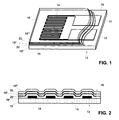
- FIG. 1 shows, in a three-dimensional representation, a single strain gage 13 arranged on a support 15, which has a strain-dependent resistance path 14, which is preferably meander-shaped on a support 15, and connection electrodes 17, and which is provided with a multilayer layer 16.
- the multi-layer 16 is drawn transparent and broken.
- It consists of a regular sequence of polymer layers 19 ', 19 ", 19”', preferably of a polyacrylate or polymethacrylate, and barrier layers 20, of a predominantly inorganic insulator, wherein the polymer layers 19 ', 19 ", 19”' have a thickness of typically 50 to 500 nm, preferably 100 nm to 200 nm, in individual cases but also beyond a layer thickness of up to 1500 nm may have.
- the layer thickness of the barrier layers 20 is typically between 5 nm and 200 nm, preferably between 10 nm and 50 nm, and in individual cases can also be up to 500 nm.
- the side edges of the carrier 15 are not shown covered in the figure 1 of the multi-layer layer.
- FIG. 2 shows a section through a strain gauge 13 with an applied multilayer layer 16 consisting of a total of five thin individual layers.
- the drawing is highly schematic and it is the respective thickness of the carrier 15, the resistor track 14 and the barrier layers 20 and the polymer layers 19 ', 19 ", 19"' drawn here not to scale.
- the first layer 19 'of the multilayer 16 directly adjacent to the carrier 15 and in the regions of the resistive track 14 applied to the carrier 15, the latter contacting the carrier and resistor tracks is preferably an acrylate polymer layer which serves to increase the roughnesses of the carrier 15 and resistor track 14 smooth. It may possibly have a greater thickness than the other polymeric intermediate layers 19 "of the multi-layer layer 16. With such acrylate polymer layers, the roughness of a substrate in the nanometer range can be smoothed out in that the formation of pinholes in the first barrier layer 20 is reduced by the smoothing effect of its backing.
- Another reason for making the first polymer layer 19 'of the multilayered layer 16 somewhat thicker compared to the remaining polymer layers 19 ", 19"' is that there is a requirement to completely cover the lateral edges of the resistance path 14.
- Said polymer layer fulfills this requirement by virtue of its properties on the one hand on a nanometer scale and on the other hand its properties covering on the micrometer scale both to a certain extent and covering the surfaces extending predominantly perpendicular to the layer plane. Thus, it creates the prerequisite for the formation of uniformly thick and defect-poor barrier layers 20 and subsequent layers of the multilayer 16.
- the first barrier layer 20 is followed by a polymeric interlayer. Their function is not only to stabilize the first barrier layer 20, but also to reduce the formation of pinholes in a further barrier layer 20 following the intermediate layer 19 ", but in particular the interlayer 19 avoids the fact that it is nevertheless produced in small numbers Pinholes a second barrier layer 20 to be fixed to those of the first barrier layer 20, which would favor the passage of moisture again.
- Much more caused by the independent localization of Pinholes in the first and in the second barrier layer 20 is a kind of labyrinth for penetrating moisture, especially water or solvent molecules. This labyrinth effect results in a drastic reduction of penetrating moisture in a multilayer coating with successive barrier layers 20 and polymer layers 19 ', 19 ", 19'".
- the multi-layer layer 16 shown in FIG. 2 has five thin individual layers, of which the first layer is the ausbnende polymer layer 19 'and the boundary layer to the ambient atmosphere forming layer is again a polymer layer 19 "' to the multi-layer 16 especially against mechanical damage
- the multilayer layer 16 may have further individual layers, and the sequence of the polymer layer 19 "and the barrier layer 20 may in principle be repeated as often as desired.
- the multilayer layer 16 may also consist of a total of only three thin individual layers, preferably of a sequence of polymer layer 19 '- barrier layer 20 - polymer layer 19 "'.
- the barrier layers 20 As materials for the barrier layers 20, a variety of known, applicable in various coating methods mainly inorganic insulators can be used. Examples which may be mentioned here oxides, nitrides, fluorides, carbides, borides or combinations thereof, in particular oxi-nitrides, or mixed ceramics. In particular, silicon oxide, titanium oxide, chromium oxide, aluminum oxide, silicon nitride and titanium nitride have proved to be the material for the barrier layers 20. The so-called diamond-like carbon layers can also be used as possible barrier layers.
- Metals for example silver, aluminum, gold, chromium, copper, nickel, titanium and alloys, for example nickel-cobalt alloys, or intermetallic compounds, for example of aluminum and copper, of tungsten are also used as further materials for the barrier layers 20 and copper or of titanium and aluminum in question.
- polymers Amides, alkyds, styrenes, xylylene, phenylenes, aldehydes, esters, urethanes, epoxides, imides, phenols, ketones, and fluoropolymers or copolymers, but the list may not be exhaustive.
- the optimization between barrier effect, combinability of the barrier layer 20 and the polymer layer 19 ', 19 ", 19"' and cost effectiveness of the coating method decide on the use of the barrier layer material as well as on the use of the polymer material.
- ORMOCER Another class of materials that can be used as polymeric intermediate layers 19 "or polymer covering layer 19 '' 'are inorganic-organic hybrid polymers with the trade name" ORMOCER. "These materials are described in DE 38 28 098 A1 and DE 43 03 570 A1 Although the barrier effect is not high enough that it would be suitable for use as a barrier layer 20, a particular advantage of ORMOCER is that these materials can be deposited in air For example, by spray, spin or pad printing.
- a thin barrier layer 20 has a correspondingly low rigidity. Therefore, in conjunction with the per se flexible polymer layer 19 ', 19 ", 19"' only a minimal force shunt by the application of a multi-layer 16 with ultrathin barrier layers 20 on strain gauges 13 to be feared. For the same reason, the risk of detachment of the ultra-thin barrier layers 20 from their delamination has been massively reduced and could not be observed for materials used in the invention.
- strain gauges 13 with a multi-layer 16 following the preparation of the strain gauges 13 takes place, as long as they are still present in a series or surface arrangement, remain at a separation of the strain gauges 13, however, the side surfaces, in particular the carrier film, open and penetrating Moisture accessible. Due to the area ratios of top and side edges of a strain gauge, however, the protective effect of the inventive multi-layer 16 is still quite high. Strain gauges can be used with this extremely efficient coating method 13, whose moisture absorption, depending on the materials used by a factor of 50 to 1000 is smaller, compared to uncoated strain gauges. In the event that a higher barrier effect than that mentioned would have to be achieved, it is of course also possible to coat individual strain gauges 13, possibly completely, whereby the side surfaces of the carrier 15 would be covered, at least with careful handling.
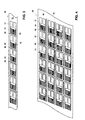
- FIG. 3 shows a series arrangement 30 of strain gauges 13.
- the carrier 31 of the series arrangement 30 is interrupted by narrow slits 32 oriented transversely to the longitudinal extent of the series arrangement 30, wherein the slits 32 do not extend beyond the slits 32 entire width of the carrier 31 of the array 30 range.
- the slits 32 may be formed after application of the resistive track 14 and the terminal electrodes 17 by various methods such as water cutting, laser cutting or, preferably, stamping in the carrier 31 as well.
- FIG. 4 shows a surface arrangement 35 of strain gauges 13 in which slots 32 and slots 34 arranged perpendicularly to each other in the regions between the individual resistance electrodes 14 connected to their respective connection electrodes 17 break through the support 36 of the surface arrangement 35 so that it only adjoins four Connecting points 37 is connected to each strain gauge 13.
- the slits 32, 34 are produced at those points of a carrier, to which at a later separation of the strain gauges 13, these from the Surface arrangement 35 are separated out.
- such a slit arrangement can be varied in many ways, for example, such that the slits make a right angle around the resistive paths 14 connected to their respective terminal electrodes 17, and are interconnected only at two or three junctions of the support 36.
- the strain gauges can be linked together at more than four joints with each other.
- connection points 33, 37 It is important to minimize the connection of the carrier 31, 36 at the connection points 33, 37, that is to keep the surface of the connection points 33, 37 so small that, on the one hand, the edges of a strain gauge 13 are covered by the protective layer in as large a range as possible can, on the other hand, but for the handling of the array 30 or surface arrangement 35 of strain gauges 13 still a sufficiently high cohesion of the carrier 31, 36 is present. It has been found that in this way it was possible to reduce the penetration of moisture into strain gauges from a series or surface arrangement of the prior art and to sustainably improve the sensitivity of a load cell subjected to such strain gauges.
- the width of a slit 32, 37 should be selected such that on the one hand not too much carrier material is lost between the individual strain gauges 13 and on the other hand the coating materials to be applied ensure sufficient coverage of the side edges of a strain gage 13.
- a width of about 0.5 mm is mentioned here as an orientation value.
- the individual barrier layers 20 are not necessarily of the same material. Nor are the polymer layers 19 ', 19 ", 19"' limited to a single material.
- the multi-layer 16 is composed of an alternating sequence of a polymer layer 19 ', 19 ", 19"', in particular a polyacrylate or polymethacrylate layer and a barrier layer 20, preferably of silicon oxide or aluminum oxide, due to the choice an efficient coating process, the materials used are uniform, as well as well as the individual layers are homogeneous in themselves.
- the boundary layer to the carrier 15 or to the resistance path 14 and the connection electrodes 17 is a polymer layer 19 ', for the boundary layer to the ambient atmosphere, this is not absolutely necessary, although preferred, since a final polymer layer 19 "' good mechanical and optionally chemical protection for a last This means that, if appropriate, the choice of the polymer material used for the final polymer layer 19 "'is carried out with regard to the property of being able to provide particularly good mechanical and / or chemical protection.
- the preferred method of forming a multilayer 16 on a series array of strain gauges 13 includes the steps of depositing a nanometer scale polymer layer 19 'having a thickness that is between 200 nm and 1500 nm, depositing an approximately 20 nm thick barrier layer 20 on the polymer layer 19 ', deposition of a further thin polymer layer 19 "with a thickness of about 100 nm to 200 nm on the barrier layer 20, any repetition of the process of coating with a barrier layer 20 and a polymer layer 19", where as a boundary layer to the ambient atmosphere a polymer layer 19 "'or a thin barrier layer 20 may be present.
- the substrate of the multi-layer layer 16 be it the substrate 15, 31, 36, to a carrier foil or the resistance track 14 for plasma cleaning or chemical cleaning.
- vapor deposition in vacuo vapor deposition in air
- plasma coating can be used here for producing the barrier layers 20.
- plasma coating "sputtering”, sol-gel process, “chemical vapor deposition (CVD)”, “combustion chemical vapor deposition (CCVD)”, “plasma enhanced chemical vapor deposition (PECVD)”, “plasma impulse chemical vapor deposition (PICVD)”
- CVD chemical vapor deposition
- CCVD combustion chemical vapor deposition
- PECVD plasma enhanced chemical vapor deposition
- PICVD plasma impulse chemical vapor deposition
- the following coating methods are possible for applying the polymer layers: vapor deposition in vacuo, evaporation in air, in situ polymerization of monomers or oligomers applied by flash evaporation or plasma coating, and electrophoresis, cataphoresis or anaphoresis.
- a method for coating strain gauges 13, which can be applied to the deformation body of a load cell, has proved to be particularly efficient when the multilayer coating 16 is produced by alternating coating with polymer layers 19 ', 19 ", 19"' and barrier layers 20 within a coating apparatus done by two sources in one operation.
Abstract
Description
Die Erfindung betrifft eine Reihen- oder Flächenanordnung von Dehnmessstreifen, mit einer dehnungsempfindlichen auf einem Träger aufgebrachten elektrischen Widerstandsbahn, mit einer die Widerstandsbahn und mindestens einen Teil des Trägers bedeckenden Mehrlagenschicht. Ferner betrifft die Erfindung ein Verfahren zur Herstellung einer Mehrlagenschicht auf einer Reihen- oder Flächenanordnung von Dehnmessstreifen.The invention relates to a series or surface arrangement of strain gauges, with a strain-sensitive applied to a support electrical resistance track, with a resistance path and at least a portion of the carrier covering multi-layer. Furthermore, the invention relates to a method for producing a multi-layer on a series or surface arrangement of strain gauges.
Ein Dehnmessstreifen weist eine auf einem Träger aufgebrachte metallische Widerstandsbahn auf, welche vorzugsweise in Form einer Mäanderstruktur mittels bekanntem Ätzverfahren hergestellt wird. Femer sind auf dem Träger Anschlusselektroden zur Kontaktierung der Widerstandsbahn vorhanden, wobei diese häufig in einem Arbeitsgang mit der Widerstandsbahn entstehen und somit meist aus demselben Material bestehen. Als Trägermaterial für Dehnmessstreifen werden elektrische Isolatoren verwendet; je nach Anwendungsbereich findet man Glas, Keramik, häufig auch Polymere, glasfaserverstärkte Polymere oder Kompositmaterialien. Dehnmessstreifen sind Messelemente, bei welchen eine mechanische Verformung eine Änderung des elektrischen Widerstandes hervorruft, und welche daher zur Messung der die Verformung bewirkenden Kraft benutzt werden.A strain gauge has a metallic resistance track applied to a carrier, which is preferably produced in the form of a meander structure by means of a known etching process. Furthermore, connecting electrodes for contacting the resistor track are present on the carrier, whereby these often occur in one operation with the resistor track and thus usually consist of the same material. As support material for strain gauges electrical insulators are used; Depending on the field of application, glass, ceramics, often also polymers, glass fiber reinforced polymers or composite materials are found. Strain gauges are measuring elements in which a mechanical deformation causes a change in the electrical resistance, and which are therefore used to measure the deformation causing force.
In der Wägetechnologie, beispielsweise, werden Dehnmessstreifen zur Wandlung einer durch eine Kraft auf einen Verformungskörper bewirkten Verformung in ein elektrisches Signal verwendet. In einer solchen Kraftmesszelle entsteht eine Auslenkung des vertikal beweglichen Lastaufnehmers gegenüber dem räumlich feststehenden Teil des Verformungskörpers durch die Kraftwirkung einer Last auf der mit dem Lastaufnehmer verbundenen Waagschale. In einer bevorzugten Ausbildungsform weisen solche Verformungskörper vier durch dünne Materialbereiche geformte, elastische Biegestellen auf, welche jeweils an den vier Eckpunkten eines Parallelogramms angeordnet sind, wobei der Lastaufnehmer als vertikal beweglicher Parallelogrammschenkel gegenüber einem vorzugsweise am Waagengehäuse befestigten, ebenfalls vertikalen Parallelogrammschenkel angeordnet ist. Die Grösse der in den dünnen Biegestellen hervorgerufenen Verformung wird mit mindestens einem auf einer der Biegestellen, meist mittels einer elektrisch isolierenden Klebeschicht aufgebrachten Dehnmessstreifen als Änderung seines elektrischen Widerstands gemessen.In weighing technology, for example, strain gauges are used to convert a deformation caused by a force on a deformation body into an electrical signal. In such a load cell, a deflection of the vertically movable load receiver relative to the spatially fixed part of the deformation body by the force of a load on the weighing pan connected to the load receiver. In a preferred embodiment, such deformation bodies have four flexible regions formed by thin material regions, which are each arranged at the four corner points of a parallelogram, wherein the load receptor as a vertically movable Parallelogrammschenkel is arranged opposite a preferably attached to the balance housing, also vertical parallelogram leg. The size of the deformation caused in the thin bending points is measured with at least one strain gauge applied to one of the bending points, usually by means of an electrically insulating adhesive layer, as a change in its electrical resistance.
Aufgrund ihrer elastischen Eigenschaften werden in der Wägetechnologie bevorzugt polymere Trägermaterialien, insbesondere Polyimide, aber auch Epoxide, Phenolharze, Melamine und Ketone für Dehnmessstreifen verwendet. Polymere Träger haben den Vorteil, dass sie sich aufgrund ihrer geringeren Steifigkeit dem Verformungskörper besser anpassen. Insbesondere wird dadurch die mechanische Belastung der Klebeschicht reduziert. Hystereseeffekte oder eine Zerstörung der einen starren Träger mit einem Verformungskörper verbindenden Klebeschicht treten hier weitaus weniger auf. Zusätzlich ermöglichen polymere Trägermaterialien bei Dehnmessstreifen mit einer mäanderförmig ausgebildeten Widerstandsbahn bekanntermassen eine Lastdriftkompensation durch eine entsprechende Ausbildung der Umkehrstellen der Widerstandsbahn. Im Übrigen sind Dehnmessstreifen mit polymeren Trägem besser handhabbar und preisgünstiger herzustellen.Due to their elastic properties, preferably polymeric carrier materials, in particular polyimides, but also epoxies, phenolic resins, melamines and ketones are used for strain gauges in weighing technology. Polymeric carriers have the advantage that they adapt better to the deformation of the body due to their lower stiffness. In particular, this reduces the mechanical stress on the adhesive layer. Hysteresis effects or destruction of a rigid support with a deformation body connecting adhesive layer occur here much less. In addition, polymeric strain materials with strain gauges having a meander-shaped resistance path are known to permit load drift compensation by means of a corresponding design of the reversal points of the resistance path. Incidentally, strain gauges with polymeric carriers are easier to handle and less expensive to produce.
Polymere besitzen jedoch den Nachteil, dass sie eine relativ hohe Aufnahmefähigkeit für Wasser, aber auch für Lösungsmittel aufweisen, so dass der Feuchtigkeitsgehalt der eine Kraftmesszelle umgebenden Luft, insbesondere aber dessen Änderungen, einen nachhaltigen Einfluss auf das Messresultat hat. Beispielsweise sind die Empfindlichkeit, die Stabilität des Nullpunkts und das Kriechverhalten, die sogenannte Lastdrift, von der Feuchtigkeit - betreffend Wasser und Lösungsmitteln - beeinflusste Parameter einer mit Dehnmessstreifen als Wandler beaufschlagten Kraftmesszelle. Für die Grössenordnung der durch Änderung dieser Parameter verursachten Änderungen des Wägeresultats wurden einige zehn bis einige hundert parts-permillion (ppm) des Vollausschlages (Signal bei Volllast) im Falle einer stufenförmigen Änderung des Feuchtigkeitsgehalts der eine Kraftmesszelle umgebenden Luft von ca. 30% relativer Feuchtigkeit (rF) auf 85% rF im typischen Temperaturbereich zwischen 10°C und 40°C gemessen.However, polymers have the disadvantage that they have a relatively high absorption capacity for water, but also for solvents, so that the moisture content of a force measuring cell surrounding air, but in particular its changes, has a lasting impact on the measurement result. For example, the sensitivity, the stability of the zero point and the creep behavior, the so-called load drift, are parameters influenced by the moisture-in relation to water and solvents-of a load cell loaded with strain gauges as the transducer. For the order of magnitude of changes in the weighing result caused by changing these parameters, tens to hundreds of parts-per-million (full-load signal) in the case of stepwise change of the moisture content of the air surrounding a load cell of about 30% relative humidity (rF) measured at 85% RH in the typical temperature range between 10 ° C and 40 ° C.
Einige dieser zu Änderungen der Messresultate führenden Ursachen sind erkannt und physikalisch erklärbar. Zum Ersten nimmt das Trägermaterial eines ungeschützten Dehnmessstreifens die Feuchtigkeit auf und quillt dadurch auf, so dass sich der Abstand der Widerstandsbahn zur Biegestelle vergrössert und dadurch die von der sich verformenden Biegestelle in die Widerstandsbahn induzierte Verformung geringfügig verändert wird. Zum Zweiten ändert aufgenommene Feuchtigkeit die elastischen Eigenschaften des Trägermaterials und damit die Verformungsparameter der Widerstandsbahn. Zum Dritten kann eine erhöhte Feuchtigkeit des Trägermaterials Leckströme zwischen benachbarten Bereichen einer mäanderförmigen Widerstandsbahn, oder gar zwischen der Widerstandsbahn und dem metallischen Verformungskörper hervorrufen. Diese Effekte sind zwar relativ zum Vollausschlag klein, wie oben genannte Messwerte zeigen, jedoch für eine Kraftmesszelle, die höchsten Genauigkeitsanforderungen zu genügen hat, ist ihr Einfluss auf das Messsignal noch zu gross. Daher sind Schutzvorrichtungen und/oder Schutzmassnahmen erforderlich, um ein von Umgebungseinflüssen, insbesondere von auf das Trägermaterial und/oder die Widerstandsbahn einwirkender Feuchtigkeit, weitgehend unbeeinflusstes Messsignal zu erhalten.Some of these causes leading to changes in the measurement results are recognized and can be explained physically. First, the carrier material of an unprotected strain gauge absorbs the moisture and thereby swells, so that the distance of the resistance path to the bending point increases and thereby the deformation induced by the deforming bending point into the resistance path is slightly changed. Secondly, absorbed moisture changes the elastic properties of the carrier material and thus the deformation parameters of the resistance path. Thirdly, increased moisture of the carrier material can cause leakage currents between adjacent regions of a meander-shaped resistance path, or even between the resistance path and the metallic deformation element. Although these effects are small relative to the full scale, as shown in the above-mentioned measurements, their influence on the measurement signal is still too great for a load cell which has to meet the highest accuracy requirements. Therefore, protective devices and / or protective measures are required in order to obtain a measurement signal which is largely uninfluenced by environmental influences, in particular moisture acting on the carrier material and / or the resistance path.
Im Stand der Technik sind solche Massnahmen zum Schutz von Dehnmessstreifen vor eine Veränderung des Messsignals bewirkender Feuchtigkeit bekannt. So beschreibt die DE 27 28 916 A1 die Bedeckung eines auf einem Messgrössenaufnehmer aufgebrachten Dehnmessstreifens. Zunächst wird eine elektrisch isolierende Schicht, beispielsweise ein Harz aufgebracht, beziehungsweise der Dehnmessstreifen wird in diese Schicht eingebettet, so dass auch ein Teil des Aufnehmerkörpers um den Dehnmessstreifen abgedeckt wird. Auf die elektrisch isolierende Schicht wird eine Metallschicht angeordnet, die ebenfalls einen Teil des Aufnehmerkörpers um den Dehnmessstreifen abdeckt. Somit kann eine Kapselung gegen Feuchtigkeit für einen bereits auf einem Aufnehmer aufgebrachten Dehnmessstreifen erreicht werden.In the prior art, such measures for protecting strain gauges from a change in the measurement signal causing moisture are known. Thus, DE 27 28 916 A1 describes the covering of a strain gauge applied to a sensor. First, an electrically insulating layer, for example a resin is applied, or the strain gauge is embedded in this layer, so that a part of the transducer body is covered by the strain gauge. On the electrically insulating layer, a metal layer is arranged, which also covers a part of the transducer body to the strain gauge. Thus, encapsulation against moisture can be achieved for a strain gauge already applied to a transducer.
Aus der US 5 631 622 ist eine Schutzmassnahme gegen Feuchtigkeit für Dehnmessstreifen bekannt, bei der anschliessend an deren Herstellung in einer Flächenanordnung, noch vor der Vereinzelung der Dehnmessstreifen, zunächst eine elektrisch isolierende Polymerschicht auf die Dehnmessstreifen aufgebracht wird und darauf eine Metallfolie als zusätzliche Abdeckung laminiert wird. Auch nach der Vereinzelung ist ein Dehnmessstreifen grossflächig durch die Metallfolie gegen Feuchtigkeitseinwirkung geschützt.From US Pat. No. 5,631,622 a moisture protection measure for strain gauges is known in which an electrically insulating polymer layer is first applied to the strain gauges and then a metal foil is laminated thereon as an additional covering, prior to its production in a surface arrangement, prior to the separation of the strain gauges becomes. Even after the Singling is a strain gauge over a large area protected by the metal foil against moisture.
Um einen Dehnmessstreifen vor Korrosion zu schützen und die Messeigenschaften zu verbessern, wird in der JP 7 113 697 A vorgeschlagen, dass zur Verhinderung des Eindringens von Feuchtigkeit ein dünner anorganischer Film, beispielsweise SiO2 mit einer Dicke von etwa 100 Nanometern (nm), sozusagen als Feuchtigkeitsbarriereschicht auf die Oberfläche des Dehnmessstreifens aufgebracht wird. Anschliessend wird ein anorganischer Isolationsfilm, beispielsweise Polyimid mit einer Dicke von etwa 10 Mikrometern (pm) aufgebracht, mittels dessen mikroskopisch kleine Löcher oder Risse im anorganischen Film, sogenannte Pinholes, durch welche weiterhin Feuchtigkeit eindringen könnte, verstopft werden. Die durch diese zweilagige Schicht erzeugte Schutzwirkung ist nicht immer befriedigend, insbesondere bei den für relativ niedrige Lasten ausgelegten, hochempfindlichen Kraftmesszellen.In order to protect a strain gauge against corrosion and to improve the measuring properties, it is proposed in JP 7 113 697 A that a thin inorganic film, for example SiO 2 with a thickness of about 100 nanometers (nm), so to speak to prevent the ingress of moisture is applied as a moisture barrier layer on the surface of the Dehnmessstreifens. Subsequently, an inorganic insulating film, for example polyimide, having a thickness of about 10 micrometers (pm) is deposited, by means of which microscopic holes or cracks in the inorganic film, so-called pinholes, through which moisture could continue to penetrate, are clogged. The protective effect provided by this two-ply layer is not always satisfactory, especially with the high-sensitivity load cells designed for relatively low loads.
Die DE 40 15 666 C2 offenbart einen mit Dehnmessstreifen beaufschlagten Kraftaufnehmer, wobei ein Dehnmessstreifen und der daran angrenzende Teil des Trägers mit einer aufgedampften diffusionsdichten elektrisch isolierenden Beschichtung aus Siliziumoxid oder Siliziumkarbid versehen wird, deren Schichtdicke vorzugsweise zwei bis vier Mikrometer beträgt. In einer anderen Ausführungsform kann die Beschichtung auch aus einer unteren Siliziumoxidschicht und einer darüber befindlichen Metallschicht, vorzugsweise einer Nickelschicht, bestehen.DE 40 15 666 C2 discloses a strain gauge acted upon by strain gauges, wherein a strain gauge and the adjoining part of the carrier is provided with a vapor-deposited diffusion-tight electrically insulating coating of silicon oxide or silicon carbide whose layer thickness is preferably two to four microns. In another embodiment, the coating may also consist of a lower silicon oxide layer and an overlying metal layer, preferably a nickel layer.
Die Problematik bei den oben genannten Lösungen besteht darin, dass die den Dehnmessstreifen insgesamt bedeckenden Schutzschichten oder -folien, insbesondere die anorganischen Schichten oder Folien mit hoher Barrierewirkung, sei es, dass diese direkt auf den am Messgrössenaufnehmer applizierten Dehnmessstreifen, oder dass diese auf eine grossflächige Anordnung einer Vielzahl von Dehnmessstreifen anschliessend an deren Herstellung aufgebracht werden, aufgrund ihrer vergleichsweise grossen Masse und hohen Steifigkeit ebenfalls das mit dem Dehnmessstreifen ermittelte Messresultat verändern. Diese Messfehler entstehen durch einen sogenannten Kraftnebenschluss, verursacht durch die Bedeckung des Dehmessstreifens mit einer relativ dicken Schicht oder Folie in der Grössenordnung von einigen Mikrometern, wie sie der Stand der Technik offenbart. Insbesondere Metallschichten oder -folien tragen aufgrund ihrer vergleichsweise hohen Steifigkeit bereits ab einer Dicke von wenigen Mikrometern (µm) zu einem messbaren Kraftnebenschluss bei. Ein solcher Kraftnebenschluss entsteht beispielsweise dadurch, dass dicke anorganische Schutzschichten wegen ihrer hohen Steifigkeit signifikant zur Gesamtsteifigkeit der eingangs genannten Biegestellen des Verformungskörpers beitragen. Im Falle von Kraftmesszellen zum Messen kleiner Kräfte ist dies besonders problematisch, da hier die Biegestellen zum Erzielen einer hohen Empfindlichkeit nur eine geringe Dicke aufweisen. Das heisst unerwünschte Veränderungen der elastischen Eigenschaften der Schutzschicht, wie zum Beispiel anelastische Nachwirkung, hohe Inelastizität, insbesondere Dehnungshysterese, führen zu einem nicht reproduzierbaren und damit auch softwaretechnisch nicht kompensierbaren Messfehler.The problem with the abovementioned solutions is that the protective layers or films covering the strain gauges, in particular the inorganic layers or films with a high barrier effect, be it directly on the strain gauges applied to the measuring element sensor or on a large area Arrangement of a plurality of strain gauges are then applied to their preparation, also change the determined by the strain gauges measurement result due to their relatively large mass and high rigidity. These measurement errors are caused by a so-called force shunt, caused by the coverage of the Dehmessstreifens with a relatively thick layer or film on the order of a few micrometers, as disclosed in the prior art. Especially Due to their comparatively high rigidity, metal layers or foils contribute to a measurable force shunt already at a thickness of a few micrometers (μm). Such a force shunt is caused, for example, by the fact that thick inorganic protective layers contribute significantly to the overall stiffness of the above-mentioned bending points of the deformation body because of their high rigidity. In the case of force measuring cells for measuring small forces, this is particularly problematic because here the bends have only a small thickness to achieve high sensitivity. This means unwanted changes in the elastic properties of the protective layer, such as, for example, anelastic aftereffect, high inelasticity, in particular strain hysteresis, lead to a measurement error that is not reproducible and thus can not be compensated for by software engineering.
Andererseits ist es natürlich erforderlich, Durchgangsbereiche für die Feuchtigkeit, die bevorzugt in sehr dünnen Feuchtigkeitsbarriereschichten entstehen können, die sogenannten Pinholes, wie sie die JP 7 113 697 A beschreibt, in einer solchen Barriereschicht weitestgehend zu vermeiden oder zumindest deren Einfluss zu verringern.On the other hand, it is of course necessary to avoid passage areas for the moisture, which may preferably occur in very thin moisture barrier layers, the so-called pinholes, as described in JP 7 113 697 A, in such a barrier layer as far as possible or at least to reduce their influence.
Es ist daher die Aufgabe der vorliegenden Erfindung für Dehnmessstreifen eine Schutzschicht vorzuschlagen, welche das Eindringen von Feuchtigkeit verhindert. Es sollen dabei auch die Kanten eines Dehnmessstreifens, insbesondere seines Trägers, in einem möglichst grossen Bereich von der Schutzschicht bedeckt werden können. Femer soll für auf einen Verformungskörper einer Kraftmesszelle aufbringbare Dehnmessstreifen ein Kraftnebenschluss vermieden oder zumindest erheblich verringert werden.It is therefore the object of the present invention for strain gauges to propose a protective layer which prevents the ingress of moisture. It should also the edges of a strain gauge, in particular its carrier, can be covered in the largest possible range of the protective layer. Furthermore, force shunting should be avoided or at least considerably reduced for strain gauges that can be applied to a deformation body of a load cell.
Diese Aufgabe wird durch eine Reihen oder Flächenanordnung von Dehnmessstreifen gemäss Anspruch 1 sowie durch ein Verfahren zur Erzeugung einer solchen gemäss Anspruch 8 gelöst.This object is achieved by a series or surface arrangement of strain gauges according to claim 1 and by a method for producing such according to claim 8.
Ein Dehnmessstreifen derselben weist eine dehnungsempfindliche auf einem Träger aufgebrachte elektrische Widerstandsbahn und Anschlusselektoden zur Kontaktierung der Widerstandsbahn auf. Erfindungsgemäss ist der Träger der Reihen- oder Flächenanordnung durch eine Schlitzanordnung durchbrochen, wobei Verbindungsstellen vorhanden sind, durch welche die Träger benachbarter Dehnmessstreifen miteinander verbunden sind. Auf die mit einer Schlitzanordnung versehene Reihen- oder Flächenanordnung von Dehnmessstreifen ist eine Mehrlagenschicht als Schutzschicht aufgebracht, deren einzelne Schichten im Verlauf des Aufbringens auf der jeweiligen Unterlage haftend erzeugt wurden.A strain gauge of the same has a strain-sensitive on a support applied electrical resistance path and Anschlußelektoden for contacting the resistance path. According to the invention, the carrier of the series or Surface arrangement pierced by a slot arrangement, wherein connection points are present, through which the carriers of adjacent strain gauges are interconnected. On the row or surface arrangement of strain gauges provided with a slot arrangement, a multi-layer layer is applied as a protective layer, the individual layers of which have been adhesively produced in the course of application to the respective substrate.
In einer vorteilhaften Ausführungsform der Reihen oder Flächenanordnung von Dehnmessstreifen besteht die Schlitzanordnung aus sich entlang den Seiten eines Dehnmessstreifens erstreckenden Schlitzen, wobei jeder Schlitz sich über nahezu die gesamte entsprechende Seitenlänge eines Dehnmessstreifens erstreckt. Insbesondere im Fall einer Flächenanordnung von Dehnmessstreifen können jedoch die Schlitze auch einen rechten Winkel bildend um die mit ihren jeweiligen Anschlusselektroden verbundenen Widerstandsbahnen teilweise herum reichen und nur noch an zwei oder drei Verbindungsstellen des Trägers miteinander verknüpft sein.In an advantageous embodiment of the series or areal arrangement of strain gauges, the slot arrangement consists of slots extending along the sides of a strain gauge, each slot extending over nearly the entire corresponding side length of a strain gauge. In particular, in the case of a surface arrangement of strain gauges, however, the slots may also extend partially around the resistance paths connected to their respective terminal electrodes forming a right angle and be interconnected only at two or three connection points of the carrier.
Ein Verfahren zur Erzeugung einer Mehrlagenschicht als Schutzschicht auf einer Reihen- oder Flächenanordnung von Dehnmessstreifen nach Anspruch 6 trägt ebenfalls zur Lösung der Aufgabe bei. Bei einer Reihen- oder Flächenanordnung von Dehnmessstreifen, wobei die Dehnmessstreifen eine dehnungsempfindliche auf einem Träger aufgebrachte elektrische Widerstandsbahn und Anschlusselektoden zur Kontaktierung der Widerstandsbahn aufweisen, wird vor dem Beschichtungsvorgang der Träger durch eine jeden einzelnen Dehnmessstreifen umgebende Schlitzanordnung durchbrochen. Dabei entstehen Verbindungsstellen, durch welche die Träger benachbarter Dehnmessstreifen miteinander verbunden sind. Anschliessend wird auf die mit einer Schlitzanordnung versehene Reihen- oder Flächenanordnung von Dehnmessstreifen eine Mehrlagenschicht als Schutzschicht aufgebracht wird, deren einzelne Schichten im Verlauf des Aufbringens auf der jeweiligen Unterlage haftend erzeugt werden.A method for producing a multilayer film as a protective layer on a series or areal arrangement of strain gauges according to claim 6 also contributes to the solution of the problem. In a series or surface arrangement of strain gauges, wherein the strain gauges have a strain-sensitive applied on a support electrical resistance track and Anschlußelektoden for contacting the resistor track, the carrier is pierced by a slot arrangement surrounding each individual strain gauge prior to the coating process. This results in joints through which the carrier adjacent strain gauges are connected. Subsequently, a multi-layer layer is applied as a protective layer on the provided with a slot array row or surface arrangement of strain gauges, the individual layers are generated in the course of application to the respective substrate adhesive.
In spezieller Ausgestaltung wird eine Schlitzanordnung aus sich entlang den Seiten eines Dehnmessstreifens erstreckenden Schlitzen, insbesondere durch Ausstanzen von Material aus dem Träger erzeugt, wobei jeder Schlitz sich über nahezu die gesamte entsprechende Seitenlänge eines Dehnmessstreifens erstreckt.In a particular embodiment, a slot assembly is formed from slots extending along the sides of a strain gauge, in particular by stamping material from the carrier, each slot extending over nearly the entire corresponding side length of a strain gauge.
Durch die erfindungsgemässe Verbesserung einer Reihen oder Flächenanordnung von Dehnmessstreifen sowie vermittels des Verfahrens zur Erzeugung einer solchen bleiben bei einer Vereinzelung der Dehnmessstreifen die Seitenflächen, insbesondere des Trägers nicht mehr offen. Dabei ist darauf zu achten, die Verknüpfung des Trägers an den Verbindungsstellen zu minimieren, so dass einerseits die Kanten eines Dehnmessstreifens in einem möglichst grossen Bereich von der Schutzschicht bedeckt werden können, andererseits aber für die Handhabung der Reihen- oder Flächenanordnung von Dehnmessstreifen noch ein genügend hoher Zusammenhalt des Trägers vorhanden ist. Auf diese Weise kann das Eindringen von Feuchtigkeit gegenüber Dehnmessstreifen aus einer Reihen oder Flächenanordnung des Standes der Technik verringert und die Empfindlichkeit einer mit solchen Dehnmessstreifen beaufschlagten Kraftmesszelle nachhaltig verbessert werden.The inventive improvement of a series or surface arrangement of strain gauges and by means of the method for producing such remain in a separation of the strain gauges, the side surfaces, in particular of the carrier no longer open. It is important to ensure that the linkage of the carrier at the joints to minimize, so that on the one hand the edges of a strain gauge can be covered in the largest possible range of the protective layer, on the other hand enough for handling the series or surface arrangement of strain gauges high cohesion of the carrier is present. In this way, the penetration of moisture against strain gauges from a series or surface arrangement of the prior art can be reduced and the sensitivity of a force measuring cell loaded with such strain gauges can be sustainably improved.
Die als Mehrlagenschicht ausgebildete Schutzschicht auf der Reihen oder Flächenanordnung setzt sich in vorteilhafter Ausbildung aus einer abwechselnden Folge von einer Polymerschicht und einer Barriereschicht zusammen, wobei die Mehrlagenschicht aus mindestens drei dünnen Einzelschichten gebildet wird. Insbesondere kann eine Polymerschicht die Grenzschicht der Mehrlagenschicht zum Träger und/oder der Widerstandsbahn bilden, welche Polymerschicht die Oberfläche des zu beschichtenden Bereichs hinsichtlich Rauhigkeiten ausebnet und Kanten und senkrecht zur Schichtebene verlaufende Flächen bedeckt. Auf dieser Polymerschicht wird eine dünne Barriereschicht abgeschieden, welcher Barriereschicht eine weitere dünne Polymerschicht folgt. Der Vorgang des Beschichtens mit einer abwechselnden Folge von einer dünnen Barriereschicht und einer dünnen Polymerschicht kann beliebig oft wiederholt werden, wobei als Grenzschicht zur Umgebungsatmosphäre eine Polymerschicht oder eine dünne Barriereschicht (20) vorhanden sein kann.The protective layer formed as a multi-layer layer on the row or surface arrangement is composed in an advantageous embodiment of an alternating sequence of a polymer layer and a barrier layer, wherein the multi-layer layer is formed from at least three thin individual layers. In particular, a polymer layer can form the boundary layer of the multilayer to the support and / or the resistance track, which polymer layer outlines the surface of the area to be coated with respect to roughness and covers edges and surfaces perpendicular to the layer plane. On this polymer layer, a thin barrier layer is deposited, which barrier layer is followed by another thin polymer layer. The process of coating with an alternating sequence of a thin barrier layer and a thin polymer layer can be repeated as often as desired, wherein a polymer layer or a thin barrier layer (20) can be present as a boundary layer to the ambient atmosphere.
Die Herstellung der Mehrlagenschicht kann durch abwechselnde Beschichtung mit Polymerschichten und Barriereschichten innerhalb einer Beschichtungsapparatur mittels mindestens zweier Quellen in einem Arbeitsgang erfolgen. Bevorzugt wird vor dem Beschichtungsvorgang die Unterlage der Mehrlagenschicht einer Plasmareinigung oder einer chemischen Reinigung unterzogen.The multilayer coating can be produced by alternating coating with polymer layers and barrier layers within a coating apparatus by means of at least two sources in one operation. Preferably, before the coating process, the pad of the multi-layer is subjected to a plasma cleaning or a dry cleaning.
Die Erfindung nutzt somit femer die ausgezeichneten Barriereeigenschaften, welche die vorwiegend anorganischen Materialien aufweisen, aus und reduziert durch die Verwendung sehr dünner Barriereschichten die an sich sehr hohe Steifigkeit von dicken anorganischen Schichten, welche im Stand der Technik verwendet werden. Dies erfolgt durch eine Mehrfachbeschichtung aus einer abwechselnden Folge von dünnen Barriereschichten und dünnen Polymerschichten. Polymerschichten, die zwar nur eine mässige Barrierewirkung zeigen, und daher oftmals für sich alleine keinen ausreichenden Feuchtigkeitsschutz bieten können, dafür aber eine erheblich geringere Steifigkeit besitzen, sind dazu geeignet, zusammen mit dünnen, vorwiegend anorganischen Barriereschichten der Mehrlagenschicht insgesamt eine niedrige Steifigkeit zu verleihen. Auf diese Weise bleiben die eingangs erwähnten mit der geringen Steifigkeit verbundenen Vorteile eines polymeren Trägermaterials für einen Dehnmessstreifen erhalten. Durch sehr dünnen Barriereschichten innerhalb der Mehrlagenschicht wird die Gefahr oben beschriebenen Kraftnebenschlusses weitestgehend vermieden. Die Steifigkeit einer etwa 5 Nanometer (nm) bis 200 Nanometer (nm), in Einzelfällen bis 500 nm, vorzugsweise jedoch 10 nm bis 50 nm, dicken vorwiegend anorganischen Isolator- oder Metallschicht als Barriereschicht ist gering und liegt etwa in der gleichen Grössenordnung, wie die der ihr benachbarten Polymerschichten.The invention thus further exploits the excellent barrier properties exhibited by the predominantly inorganic materials and, by using very thin barrier layers, reduces the inherently very high rigidity of thick inorganic layers used in the prior art. This is done by a multiple coating of an alternating sequence of thin barrier layers and thin polymer layers. Polymeric coatings that show only a moderate barrier effect, and therefore often can not provide sufficient moisture protection on their own, but have a significantly lower rigidity, are suitable, together with thin, predominantly inorganic barrier layers of the multilayer coating to give a low overall rigidity. In this way, the advantages of a polymeric carrier material for a strain gauge, which are associated with the low rigidity mentioned above, are retained. Very thin barrier layers within the multi-layer layer largely avoid the risk of force bypass described above. The rigidity of about 5 nanometers (nm) to 200 nanometers (nm), in some cases up to 500 nm, but preferably 10 nm to 50 nm, thick inorganic insulator or metal layer as a barrier layer is low and is about the same order those of their adjacent polymer layers.
Die aus der Beschichtungstechnologie für dünne Schichten bekannten, sogenannten Pinholes, das heisst mikroskopisch kleine Löcher oder auch Risse in den Barriereschichten, werden durch die Polymerschichten innerhalb der Mehrlagenschicht ebenfalls reduziert. Grösse und Anzahl der Pinholes in einer Barriereschicht hängen nämlich, neben vielen anderen Beschichtungsparametern und natürlich dem Schichtmaterial, auch von der Rauhigkeit und Ebenheit des Untergrundes ab, aber nur wenig von der Schichtdicke. Durch einen ausebnenden Effekt der Polymerschichten wird die Entstehung von Pinholes weitgehend vermieden oder zumindest deren Einfluss verringert. Die Abfolge von dünnen Barriereschichten mit einer Dicke von etwa 5 nm bis 200 nm, in Einzelfällen bis 500 nm, vorzugsweise jedoch 10 nm bis 50 nm, und Polymerschichten der Dicke von 50 nm bis etwa 1500 nm bewirkt für obengenannte Pinholes erstens eine gewisse Abdichtung und zweitens gewährleistet sie, dass Pinholes zweier "benachbarter" Barriereschichten örtlich versetzt sind, und behindert das Eindringen von Feuchtigkeit an solchen Schwachstellen in Form eines Labyrinths für die Wasser- und die Lösungsmittelmoleküle. Somit kann für Dehnmessstreifen ein effizienter Feuchtigkeitsschutz erzielt werden, ohne dass das Messergebnis beeinträchtigt wird.The so-called pinholes known from coating technology for thin layers, ie microscopic holes or even cracks in the barrier layers, are likewise reduced by the polymer layers within the multilayer coating. The size and number of pinholes in a barrier layer depend, in addition to many other coating parameters and, of course, the layer material, on the roughness and evenness of the substrate, but only slightly on the layer thickness. By a ausbnenden effect of the polymer layers, the formation of pinholes is largely avoided or at least reduced their influence. The sequence of thin barrier layers with a thickness of about 5 nm to 200 nm, in individual cases up to 500 nm, but preferably 10 nm to 50 nm, and polymer layers of thickness from 50 nm to about 1500 nm causes for the above-mentioned pinholes, first, some sealing and secondly, it ensures that pinholes of two "adjacent" barrier layers are spatially offset, and hinders the penetration of moisture at such weak points in the form of a labyrinth for the water and the solvent molecules. Thus, for strain gauges, efficient moisture protection can be achieved without affecting the measurement result.
Durch die Erfindung wird ein weiterer, mit dicken anorganischen Barriereschichten verbundener Nachteil beseitigt, nämlich der der Gefahr eines Ablösens der Schicht, der sogenannten Delamination. Diese Delamination entsteht dadurch, dass durch die hohe Steifigkeit einer vergleichsweise dicken Barriereschicht der Übergang von der Oberfläche des Dehnmessstreifens zur Barriereschicht erheblichen mechanischen Spannungen ausgesetzt ist. Die erfindungsgemässe Verwendung von dünnen Barriereschichten in abwechselnder Folge mit dünnen Polymerschichten besitzt hinsichtlich des unerwünschten Lösens einer Barriereschicht von ihrer Unterlage eine sehr hohe Stabilität.The invention eliminates another disadvantage associated with thick inorganic barrier layers, namely the risk of delamination of the layer, the so-called delamination. This delamination arises from the fact that the high stiffness of a comparatively thick barrier layer, the transition from the surface of the strain gauge to the barrier layer is exposed to considerable mechanical stresses. The use according to the invention of thin barrier layers in alternating sequence with thin polymer layers has a very high stability with regard to the undesired release of a barrier layer from its base.
In ihrer Verwendung als gesamthaft dünne, mehrlagige Schutzschichten mit einer Abfolge von dünnen, vorwiegend anorganischen Barriereschichten und ausebnenden Polymerschichten bedecken die Mehrlagenschichten einen auf einer Kraftmesszelle aufbringbaren Dehnmessstreifen. Dabei dienen sie hauptsächlich dazu, die negativen Einflüsse ansonsten eindringender Feuchtigkeit auf das mit einer solchen Kraftmesszelle gemessene Ergebnis zu minimieren und gleichzeitig einen eben dieses Messergebnis verfälschenden Kraftnebenschluss, welcher beispielsweise bei der Verwendung dicker Barriereschichten oder -folien entsteht, weitgehend zu verhindern.When used as a whole, thin, multi-layered protective layers with a sequence of thin, predominantly inorganic barrier layers and ausbnenden polymer layers, the multilayer coatings cover a strain gauge can be applied to a load cell. They serve mainly to minimize the negative influences of otherwise penetrating moisture on the measured result with such a load cell result and at the same time to prevent just this measurement falsifying force shunt, which arises for example when using thicker barrier layers or films largely.
Auf diese Weise ist es möglich, die Empfindlichkeit von Kraftmesszellen mit einem oder mehreren auf einem Verformungskörper als Wandler applizierten Dehnmessstreifen nachhaltig zu verbessern, so dass beispielsweise die Auflösung von mit solchen Kraftmesszellen versehenen Waagen einem Bereich zugänglich wird, der bis anhin nur Waagen mit nach dem Prinzip der elektromagnetischen Kraftkompensation arbeitenden Kraftmesszellen zugänglich war.In this way, it is possible to sustainably improve the sensitivity of load cells with one or more strain gauges applied to a deformation body as a transducer, so that, for example, the resolution of scales provided with such load cells becomes accessible to an area which until now has only been able to use scales Principle of electromagnetic force compensation working force cells was accessible.
In der folgenden Beschreibung ist die Erfindung anhand von Ausführungsbeispielen unter Bezugnahme auf die stark schematisierten Zeichnungen näher erläutert. Es zeigen:
- Figur 1
- einen einzelnen Dehnmessstreifen mit einer aufgebrachten Mehrlagenschicht in dreidimensionaler Darstellung,
- Figur 2
- einen einzelnen Dehnmessstreifen mit einer aufgebrachten Mehrlagenschicht im Schnitt,
- Figur 3
- eine Reihenanordnung von Dehnmessstreifen mit Schlitzen im Trägermaterial zwischen benachbarten Dehnmessstreifen,
- Figur 4
- eine Flächenanordnung von Dehnmessstreifen mit Schlitzen im Trägermaterial zwischen benachbarten Dehnmessstreifen.
- FIG. 1
- a single strain gauge with an applied multilayer coating in three-dimensional representation,
- FIG. 2
- a single strain gauge with an applied multilayer coating in section,
- FIG. 3
- a series arrangement of strain gauges with slots in the substrate between adjacent strain gauges,
- FIG. 4
- a surface arrangement of strain gauges with slots in the substrate between adjacent strain gauges.
Figur 1 zeigt in dreidimensionaler Darstellung einen einzelnen auf einem Träger 15 angeordneten Dehnmessstreifen 13, welcher eine dehnungsabhängige Widerstandsbahn 14, die vorzugsweise mäanderförmig auf einem Träger 15 angeordnet ist, sowie Anschlusselektroden 17 aufweist, und der mit einer Mehrlagenschicht 16 versehen ist. Der Übersicht halber ist hier die Mehrlagenschicht 16 durchsichtig und gebrochen gezeichnet. Sie besteht aus einer regulären Abfolge von Polymerschichten 19', 19", 19"', vorzugsweise aus einem Polyacrylat oder Polymethacrylat, und Barriereschichten 20, aus einem vorwiegend anorganischen Isolator, wobei die Polymerschichten 19', 19", 19"' eine Dicke von typischerweise 50 bis 500 nm, vorzugsweise 100 nm bis 200 nm aufweisen, in Einzelfällen aber auch darüber hinausgehend eine Schichtdicke von bis zu 1500 nm besitzen können. Die Schichtdicke der Barriereschichten 20 liegt typischerweise zwischen 5 nm und 200 nm, vorzugsweise zwischen 10 nm und 50 nm, kann in Einzelfällen auch bis zu 500 nm betragen.FIG. 1 shows, in a three-dimensional representation, a
Die Seitenkanten des Trägers 15 sind in der Figur 1 nicht von der Mehrlagenschicht bedeckt eingezeichnet.The side edges of the
Der Aufbau und die bevorzugte Abfolge der Einzellagen oder -schichten in der Mehrlagenschicht 16 kommt in der Figur 2 zum Ausdruck, welche einen Schnitt durch einen Dehnmessstreifen 13 mit einer aus insgesamt fünf dünnen Einzelschichten bestehenden aufgebrachten Mehrlagenschicht 16 zeigt. Allerdings ist die Zeichnung stark schematisiert und es sind die jeweilige Dicke des Trägers 15, der Widerstandsbahn 14 und der Barriereschichten 20 sowie der Polymerschichten 19', 19", 19"' hier nicht massstabgetreu gezeichnet.The structure and the preferred sequence of the individual layers or layers in the
Die dem Träger 15 und in den Bereichen der auf dem Träger 15 aufgebrachten Widerstandsbahn 14 letzterer direkt benachbarte und Träger und Widerstandsbahn berührende erste Schicht 19' der Mehrlagenschicht 16 ist bevorzugt eine Acrylat-Polymerschicht, welche dazu dient, Rauhigkeiten von Träger 15 und Widerstandsbahn 14 zu glätten. Sie kann unter Umständen eine höhere Dicke aufweisen, als die weiteren polymeren Zwischenschichten 19" der Mehrlagenschicht 16. Mit solchen Acrylat-Polymerschichten kann die Rauhigkeit einer Unterlage im Nanometerbereich ausgeebnet werden. Auf diese Weise wird die Bildung einer fehlstellenarmen folgenden Barriereschicht 20 begünstigt, das heisst, dass das Entstehen von Pinholes in der ersten Barriereschicht 20 durch die glättende Wirkung ihrer Unterlage verringert wird.The first layer 19 'of the multilayer 16 directly adjacent to the
Ein weiterer Grund, die erste Polymerschicht 19' der Mehrlagenschicht 16 verglichen mit den übrigen Polymerschichten 19", 19"' etwas dicker aufzubringen, besteht darin, dass die Forderung besteht, die seitlichen Kanten der Widerstandsbahn 14 vollständig zu bedecken. Eine genannte Polymerschicht erfüllt diese Forderung durch ihre einerseits auf Nanometerskala ausebnenden Eigenschaften und andererseits ihrer auf Mikrometerskala sowohl in gewissem Masse ausebnenden als auch die vorwiegend senkrecht zur Schichtebene verlaufende Flächen abdeckenden Eigenschaften. Somit schafft sie die Voraussetzung für die Bildung von gleichmässig dicken und fehlstellenarmen Barriereschichten 20 und folgenden Schichten der Mehrlagenschicht 16.Another reason for making the first polymer layer 19 'of the
Auf die erste Barriereschicht 20 folgt eine polymere Zwischenschicht. Ihre Funktion ist neben der Stabilisierung der ersten Barriereschicht 20 auch eine Reduktion der Entstehung von Pinholes in einer weiteren, der Zwischenschicht 19" folgenden Barriereschicht 20 durch ihre glättende Wirkung. Insbesondere wird aber durch die Zwischenschicht 19" vermieden, dass die dennoch in geringer Anzahl entstandenen Pinholes einer zweiten Barriereschicht 20 sich an solchen der ersten Barriereschicht 20 fixieren, was den Feuchtigkeitsdurchgang wieder begünstigen würde. Vielmehr entsteht durch die voneinander unabhängige Lokalisierung der Pinholes in der ersten und in der zweiten Barriereschicht 20 eine Art Labyrinth für eindringende Feuchtigkeit, insbesondere Wasser oder Lösungsmittelmoleküle. Dieser Labyrintheffekt führt in einer mehrlagigen Beschichtung mit aufeinander folgenden Barriereschichten 20 und Polymerschichten 19', 19", 19''' zu einer drastischen Reduktion eindringender Feuchtigkeit.The
Die in der Figur 2 gezeigte Mehrlagenschicht 16 weist fünf dünne Einzelschichten auf, wovon die erste Schicht die ausebnende Polymerschicht 19' ist und die die Grenzschicht zur Umgebungsatmosphäre bildende Schicht wiederum eine Polymerschicht 19"' ist, um die Mehrlagenschicht 16 vor allem gegen mechanische Beschädigung zu stabilisieren. Die Mehrlagenschicht 16 kann noch weitere Einzelschichten aufweisen; die Sequenz aus Polymerschicht 19" und Barriereschicht 20 kann im Prinzip beliebig oft wiederholt werden. Die Mehrlagenschicht 16 kann aber auch aus insgesamt nur drei dünnen Einzelschichten bestehen, bevorzugterweise aus einer Abfolge von Polymerschicht 19' ― Barriereschicht 20 ― Polymerschicht 19"'.The
Als Materialien für die Barriereschichten 20 sind eine Vielzahl der bekannten, in verschiedenen Beschichtungsverfahren aufbringbaren vorwiegend anorganischen Isolatoren verwendbar. Als Beispiele seien hier Oxide, Nitride, Fluoride, Karbide, Boride oder Kombinationen davon, insbesondere Oxi-Nitride, oder auch Mischkeramiken genannt. Insbesondere haben sich Siliziumoxid, Titanoxid, Chromoxid, Aluminiumoxid, Siliziumnitrid und Titannitrid als Material für die Barriereschichten 20 bewährt. Auch die sogenannten "diamond-like carbon"-Schichten können als mögliche Barriereschichten 20 Verwendung finden.As materials for the barrier layers 20, a variety of known, applicable in various coating methods mainly inorganic insulators can be used. Examples which may be mentioned here oxides, nitrides, fluorides, carbides, borides or combinations thereof, in particular oxi-nitrides, or mixed ceramics. In particular, silicon oxide, titanium oxide, chromium oxide, aluminum oxide, silicon nitride and titanium nitride have proved to be the material for the barrier layers 20. The so-called diamond-like carbon layers can also be used as possible barrier layers.
Als weitere Materialien für die Barriereschichten 20 kommen insbesondere auch Metalle, beispielsweise Silber, Aluminium, Gold, Chrom, Kupfer, Nickel, Titan, sowie Legierungen, beispielsweise Nickel-Kobalt-Legierungen, oder intermetallische Verbindungen, zum Beispiel aus Aluminium und Kupfer, aus Wolfram und Kupfer oder aus Titan und Aluminium in Frage.Metals, for example silver, aluminum, gold, chromium, copper, nickel, titanium and alloys, for example nickel-cobalt alloys, or intermetallic compounds, for example of aluminum and copper, of tungsten are also used as further materials for the barrier layers 20 and copper or of titanium and aluminum in question.
Neben Acrylat-Polymeren können für die Polymerschichten 19', 19", 19"' auch weitere polymere Materialien Verwendung finden. Als Beispiele seien angeführt: polymere Amide, Alkyde, Styrole, Xylylene, Phenylene, Aldehyde, Estere, Urethane, Epoxide, Imide, Phenole, Ketone sowie Fluorpolymere oder Copolymere, wobei die Auflistung hier nicht abschliessend sein kann. Letztendlich entscheidet die Optimierung zwischen Barrierewirkung, Kombinierbarkeit der Barriereschicht 20 und der Polymerschicht 19', 19", 19"', sowie Wirtschaftlichkeit der Beschichtungsmethode über die Verwendung des Barriereschichtmaterials ebenso wie über die Verwendung des Polymermaterials.In addition to acrylate polymers, other polymeric materials can be used for the polymer layers 19 ', 19 ", 19"'. Examples include: polymers Amides, alkyds, styrenes, xylylene, phenylenes, aldehydes, esters, urethanes, epoxides, imides, phenols, ketones, and fluoropolymers or copolymers, but the list may not be exhaustive. Ultimately, the optimization between barrier effect, combinability of the
Eine weitere Klasse von Materialien, die als polymere Zwischenschichten 19" oder Polymere Abdeckschicht 19''' Verwendung finden können, sind anorganischorganische Hybridpolymere mit dem Handelsnamen "ORMOCER". Diese Materialien, welche in der DE 38 28 098 A1 und DE43 03 570 A1 beschrieben sind, besitzen eine gute Elastizität und eine gewisse Barrierewirkung gegenüber eindringender Feuchtigkeit. Allerdings ist die Barrierewirkung nicht hoch genug, als dass sie sich für eine Verwendung als Barriereschicht 20 eignen würde. Ein besonderer Vorteil von ORMOCERen ist, dass diese Materialien an Luft abgeschieden werden können, beispielsweise durch Sprüh-, Schleuder- oder Tampondruckverfahren.Another class of materials that can be used as polymeric
Ungeachtet der Materialfrage besitzt eine dünne Barriereschicht 20 eine entsprechend geringe Steifigkeit. Daher ist im Zusammenwirken mit der an sich flexiblen Polymerschicht 19', 19", 19"' nur ein minimaler Kraftnebenschluss durch das Aufbringen einer Mehrlagenschicht 16 mit ultradünnen Barriereschichten 20 auf Dehnmessstreifen 13 zu befürchten. Aus demselben Grund ist die Gefahr des Ablösens der ultradünnen Barriereschichten 20 von ihrer Unterlage (Delamination) massiv reduziert und konnte für im Rahmen der Erfindung verwendete Materialien nicht beobachtet werden.Regardless of the material issue, a
Wenn die Beschichtung von Dehnmessstreifen 13 mit einer Mehrlagenschicht 16 im Anschluss an die Herstellung der Dehnmessstreifen 13 erfolgt, solange diese noch in einer Reihen- oder Flächenanordnung vorhanden sind, bleiben bei einer Vereinzelung der Dehnmessstreifen 13 allerdings die Seitenflächen, insbesondere der Trägerfolie, offen und eindringender Feuchtigkeit zugänglich. Aufgrund der Flächenverhältnisse von Oberseite und Seitenkanten eines Dehnmessstreifens ist jedoch die Schutzwirkung der erfindungsgemässen Mehrlagenschicht 16 immer noch recht hoch. Es können mit dieser äusserst effizienten Beschichtungsmethode Dehnmessstreifen 13 hergestellt werden, deren Feuchtigkeitsaufnahme, abhängig von den verwendeten Materialien um einen Faktor 50 bis 1000 geringer ausfällt, im Vergleich zu unbeschichteten Dehnmessstreifen. Für den Fall, dass eine höhere Barrierewirkung, als die genannte erreicht werden müsste, ist es selbstverständlich auch möglich einzelne Dehnmessstreifen 13, gegebenenfalls rundum, zu beschichten, wodurch die Seitenflächen des Trägers 15, zumindest bei vorsichtiger Handhabung, abgedeckt wären.If the coating of
Eine Möglichkeit, die Seitenkanten von Dehnmessstreifen 13 in einer Reihen- oder Flächenanordnung mit einer Schutzschicht, insbesondere in Form einer beschriebenen Mehrlagenschicht, zumindest teilweise, zu bedecken, soll anhand der Figuren 3 und 4 beschrieben werden. Die Figur 3 zeigt eine Reihenanordnung 30 von Dehnmessstreifen 13. Zwischen den einzelnen mit ihren jeweiligen Anschlusselektroden 17 verbundenen Widerstandsbahnen 14 ist der Träger 31 der Reihenanordnung 30 durch schmale, quer zur Längsausdehnung der Reihenanordnung 30 orientierte Schlitze 32 durchbrochen, wobei die Schlitze 32 nicht über die gesamte Breite des Trägers 31 der Reihenanordnung 30 reichen. Die Schlitze 32 können nach dem Aufbringen der Widerstandsbahn 14 und der Anschlusselektroden 17 durch verschiedene Verfahren, wie Wasserschneiden, Laserschneiden oder in bevorzugter Weise auch durch Stanzen im Träger 31 erzeugt werden. Dies erfolgt vor dem Bedecken der Reihenanordnung 30 mit einer Schutzschicht, insbesondere einer oben beschriebenen Mehrlagenschicht 16. Auf diese Weise sind die Ränder eines Dehnmessstreifens bis auf die noch während des Beschichtens vorhandenen möglichst klein dimensionierten Verbindungsstellen 33 des Trägers 31, welche bei der anschliessenden Vereinzelung der Dehnmessstreifen 13 durchtrennt werden, ebenfalls mit einer Schutzschicht versehen.One way to at least partially cover the side edges of
Die Figur 4 zeigt eine Flächenanordnung 35 von Dehnmessstreifen 13, in welcher in den Bereichen zwischen den einzelnen mit ihren jeweiligen Anschlusselektroden 17 verbundenen Widerstandsbahnen 14 Schlitze 32 und senkrecht dazu angeordnete Schlitze 34 den Träger 36 der Flächenanordnung 35 durchbrechen, so dass dieses lediglich an jeweils vier Verbindungsstellen 37 um jeden Dehnmessstreifen 13 verbunden ist. Die Schlitze 32, 34 werden an jenen Stellen eines Trägers erzeugt, an welchen bei einer späteren Vereinzelung der Dehnmessstreifen 13 diese aus der Flächenanordnung 35 herausgetrennt werden. Eine solche Schlitzanordnung kann jedoch in vielfältiger Weise variiert werden, beispielsweise derart dass die Schlitze einen rechten Winkel bildend um die mit ihren jeweiligen Anschlusselektroden 17 verbundenen Widerstandsbahnen 14 teilweise herum reichen und nur noch an zwei oder drei Verbindungsstellen des Trägers 36 miteinander verknüpft sind. Selbstverständlich können die Dehnmessstreifen untereinander auch an mehr als vier Verbindungsstellen miteinander verknüpft sein.FIG. 4 shows a
Wichtig ist es die Verknüpfung des Trägers 31, 36 an den Verbindungsstellen 33, 37 zu minimieren, das heisst die Fläche der Verbindungsstellen 33, 37 so gering zu halten, dass einerseits die Kanten eines Dehnmessstreifens 13 in einem möglichst grossen Bereich von der Schutzschicht bedeckt werden können, andererseits aber für die Handhabung der Reihenanordnung 30 oder Flächenanordnung 35 von Dehnmessstreifen 13 noch ein genügend hoher Zusammenhalt des Trägers 31, 36 vorhanden ist. Es hat sich gezeigt, dass auf diese Weise das Eindringen von Feuchtigkeit gegenüber Dehnmessstreifen aus einer Reihen oder Flächenanordnung des Standes der Technik verringert und die Empfindlichkeit einer mit solchen Dehnmessstreifen beaufschlagte Kraftmesszelle nachhaltig verbessert werden konnte.It is important to minimize the connection of the
Die Breite eines Schlitzes 32, 37 ist so zu wählen, dass einerseits nicht zu viel Trägermaterial zwischen den einzelnen Dehnmessstreifen 13 verloren geht und andererseits die aufzubringenden Beschichtungsmaterialien eine genügende Bedeckung der Seitenkanten eines Dehnmessstreifens 13 gewährleisten. Eine Breite von etwa 0,5 mm sei hier als Orientierungswert genannt.The width of a
Innerhalb einer Mehrlagenschicht 16 sind die einzelnen Barriereschichten 20 nicht notwendigerweise aus dem selben Material. Ebenso wenig sind die Polymerschichten 19', 19", 19"' auf ein einziges Material beschränkt.Within a multi-layer 16, the individual barrier layers 20 are not necessarily of the same material. Nor are the polymer layers 19 ', 19 ", 19"' limited to a single material.
Bevorzugt ist, dass die Mehrlagenschicht 16 aus einer abwechselnden Folge von einer Polymerschicht 19', 19", 19"', insbesondere einer Polyacrylat- oder Polymethacrylat-Schicht und einer Barriereschicht 20, vorzugsweise aus Siliziumoxid oder Aluminiumoxid, aufgebaut ist, wobei aufgrund der Wahl eines effizienten Beschichtungsverfahrens die jeweils verwendeten Materialien einheitlich sind, ebenso wie auch die einzelnen Schichten in sich homogen sind. Die Grenzschicht zum Träger 15 beziehungsweise zur Widerstandsbahn 14 und den Anschlusselektroden 17 ist eine Polymerschicht 19', für die Grenzschicht zur Umgebungsatmopshäre ist dies nicht zwingend notwendig, wenngleich bevorzugt, da eine abschliessende Polymerschicht 19"' einen guten mechanischen und gegebenenfalls chemischen Schutz für eine letzte Barriereschicht 20 bietet. Dies bedeutet, dass gegebenenfalls die Wahl des verwendeten Polymermaterials für die abschliessende Polymerschicht 19"' hinsichtlich der Eigenschaft, einen besonders guten mechanischen und/oder chemischen Schutz bieten zu können, erfolgt.It is preferred that the multi-layer 16 is composed of an alternating sequence of a
Um gegebenenfalls auftretende Probleme bei der elektrischen Kontaktierung der Widerstandsbahn 14 an den Anschlusselektroden 17 zu vermeiden, können auch diese frei von einer Beschichtung belassen werden. Hierzu ist es notwendig beim Beschichten mit Masken zu arbeiten, die die zu beschichtenden Bereiche frei lassen.In order to avoid any problems that may occur in the electrical contacting of the
Die bevorzugte Methode zur Herstellung einer Mehrlagenschicht 16 auf einer Reihenoder Flächenanordnung von Dehnmessstreifen 13 umfasst die folgenden Schritte: Aufbringen einer im Nanometerbereich ausebnenden Polymerschicht 19' mit einer Dicke, die zwischen 200 nm und 1500 nm liegt, Abscheiden einer etwa 20 nm dicken, Barriereschicht 20 auf der Polymerschicht 19', Abscheiden einer weiteren dünnen Polymerschicht 19" mit einer Dicke von etwa 100 nm bis 200 nm auf der Barriereschicht 20, beliebig häufige Wiederholung des Vorgangs des Beschichtens mit einer Barriereschicht 20 und einer Polymerschicht 19", wobei als Grenzschicht zur Umgebungsatmosphäre eine Polymerschicht 19"' oder eine dünne Barriereschicht 20 vorhanden sein kann.The preferred method of forming a multilayer 16 on a series array of
Es kann sich als nützlich erweisen, vor Beginn des Beschichtungsvorgangs die Unterlage der Mehrlagenschicht 16, sei dies der Träger 15, 31, 36 eine Trägerfolie oder die Widerstandsbahn 14 einer Plasmareinigung oder einer chemischen Reinigung zu unterziehen.It may prove useful, before the start of the coating process, to subject the substrate of the
Beim Aufbringen der Mehrlagenschicht steht eine grosse Auswahl von Beschichtungsverfahren zu Verfügung. Es seien hier für das Erzeugen der Barriereschichten 20 beispielhaft Aufdampfen im Vakuum, Aufdampfen an Luft, Plasmabeschichten, "sputtern", Sol-Gelverfahren, "chemical vapor deposition (CVD)", "combustion chemical vapor deposition (CCVD)", "plasma enhanced chemical vapor deposition (PECVD)", "plasma impulse chemical vapor deposition (PICVD)", sowie, insbesondere für das Aufbringen von Metallen, elektrochemisches Abscheiden, genannt. Für das Aufbringen der Polymerschichten sind folgende Beschichtungsmethoden möglich: Aufdampfen im Vakuum, Aufdampfen an Luft, insitu-Polymersisation von durch "flash evaporation" oder Plasmabeschichten aufgebrachten Monomeren oder Oligomeren, sowie Elektrophorese, Kataphorese oder Anaphorese.When applying the multilayer coating, a large selection of coating processes is available. By way of example, vapor deposition in vacuo, vapor deposition in air, can be used here for producing the barrier layers 20. Plasma coating, "sputtering", sol-gel process, "chemical vapor deposition (CVD)", "combustion chemical vapor deposition (CCVD)", "plasma enhanced chemical vapor deposition (PECVD)", "plasma impulse chemical vapor deposition (PICVD)" , as well as, in particular for the application of metals, electrochemical deposition, called. The following coating methods are possible for applying the polymer layers: vapor deposition in vacuo, evaporation in air, in situ polymerization of monomers or oligomers applied by flash evaporation or plasma coating, and electrophoresis, cataphoresis or anaphoresis.
Als besonders effizient erweist sich ein Verfahren zum Beschichten von auf dem Verformungskörper einer Kraftmesszelle aufbringbaren Dehnmessstreifen 13, mit einer Mehrlagenschicht 16, wenn die Herstellung der Mehrlagenschicht 16 durch abwechselnde Beschichtung mit Polymerschichten 19', 19", 19"' und Barriereschichten 20 innerhalb einer Beschichtungsapparatur mittels zweier Quellen in einem Arbeitsgang erfolgt.A method for coating
- 1313
- DehnmessstreifenStrain
- 1414
- Widerstandsbahnresistance path
- 1515
- Trägercarrier
- 1616
- MehrlagenschichtMultilayer
- 1717
- Anschlusselektrodenterminal electrodes
- 19'19 '
- Erste PolymerschichtFirst polymer layer
- 19"19 "
- Polymere ZwischenschichtenPolymeric interlayers
- 19"'19 " '
- Polymere AbdeckschichtPolymer cover layer
- 2020
- Barriereschichtenbarrier layers
- 3030
- Reihenanordnung von DehnmessstreifenRow arrangement of strain gauges
- 3131
- Träger der ReihenanordnungCarrier of row arrangement
- 3232
- Schlitzslot
- 3333
- Verbindungsstellejunction
- 3434
- Schlitzslot
- 3535
- Flächenanordnung von DehnmessstreifenSurface arrangement of strain gauges
- 3636
- Träger der FlächenanordnungCarrier of the surface arrangement
- 3737
- Verbindungsstellejunction
Claims (13)
Priority Applications (1)
| Application Number | Priority Date | Filing Date | Title |
|---|---|---|---|
| EP05109509A EP1686356B1 (en) | 2002-07-25 | 2003-07-22 | Moisture protection for an electromechanical transducer |
Applications Claiming Priority (3)
| Application Number | Priority Date | Filing Date | Title |
|---|---|---|---|
| EP02102061A EP1384980A1 (en) | 2002-07-25 | 2002-07-25 | Moisture protection for an electromechanical transducer |
| EP05109509A EP1686356B1 (en) | 2002-07-25 | 2003-07-22 | Moisture protection for an electromechanical transducer |
| EP03771117A EP1535035B1 (en) | 2002-07-25 | 2003-07-22 | Moisture protection for an electromechanical converter |
Related Parent Applications (2)
| Application Number | Title | Priority Date | Filing Date |
|---|---|---|---|
| EP03771117.3 Division | 2003-07-22 | ||
| EP03771117A Division EP1535035B1 (en) | 2002-07-25 | 2003-07-22 | Moisture protection for an electromechanical converter |
Publications (3)
| Publication Number | Publication Date |
|---|---|
| EP1686356A2 true EP1686356A2 (en) | 2006-08-02 |
| EP1686356A3 EP1686356A3 (en) | 2006-08-09 |
| EP1686356B1 EP1686356B1 (en) | 2011-12-07 |
Family
ID=29797288
Family Applications (3)
| Application Number | Title | Priority Date | Filing Date |
|---|---|---|---|
| EP02102061A Withdrawn EP1384980A1 (en) | 2002-07-25 | 2002-07-25 | Moisture protection for an electromechanical transducer |
| EP05109509A Expired - Lifetime EP1686356B1 (en) | 2002-07-25 | 2003-07-22 | Moisture protection for an electromechanical transducer |
| EP03771117A Expired - Lifetime EP1535035B1 (en) | 2002-07-25 | 2003-07-22 | Moisture protection for an electromechanical converter |
Family Applications Before (1)
| Application Number | Title | Priority Date | Filing Date |
|---|---|---|---|
| EP02102061A Withdrawn EP1384980A1 (en) | 2002-07-25 | 2002-07-25 | Moisture protection for an electromechanical transducer |
Family Applications After (1)
| Application Number | Title | Priority Date | Filing Date |
|---|---|---|---|
| EP03771117A Expired - Lifetime EP1535035B1 (en) | 2002-07-25 | 2003-07-22 | Moisture protection for an electromechanical converter |
Country Status (9)
| Country | Link |
|---|---|
| US (1) | US7197940B2 (en) |
| EP (3) | EP1384980A1 (en) |
| JP (1) | JP2005534020A (en) |
| CN (1) | CN100588924C (en) |
| AT (2) | ATE536538T1 (en) |
| AU (1) | AU2003262533A1 (en) |
| DE (1) | DE50312534D1 (en) |
| DK (1) | DK1535035T3 (en) |
| WO (1) | WO2004011892A1 (en) |
Cited By (3)
| Publication number | Priority date | Publication date | Assignee | Title |
|---|---|---|---|---|
| EP1560011B1 (en) * | 2004-01-27 | 2010-03-17 | Mettler-Toledo AG | Strain gauge with moisture protection by an inhomogeneous inorganic layer upon a smoothing polymer layer (ORMOCER) and an arrangement of slits |
| FR2937727A1 (en) * | 2008-10-24 | 2010-04-30 | Snecma | METHOD FOR INSTALLING AND PROTECTING A SENSOR ON A SUBSTRATE |
| FR2937726A1 (en) * | 2008-10-24 | 2010-04-30 | Snecma | Sensor installing and protecting method for e.g. rotating vane of low pressure turbine in turbojet engine, involves performing laser densification of alumina deposition surface of covering layer by localized re-melt |
Families Citing this family (34)
| Publication number | Priority date | Publication date | Assignee | Title |
|---|---|---|---|---|
| US20070062300A1 (en) * | 2003-09-25 | 2007-03-22 | Dorfman Benjamin F | Method and apparatus for straining-stress sensors and smart skin for air craft and space vehicles |
| DE102005012686A1 (en) * | 2005-01-14 | 2006-07-27 | Trafag Ag | Pressure sensor, usable therein deformation body and manufacturing method thereof |
| US8173995B2 (en) | 2005-12-23 | 2012-05-08 | E. I. Du Pont De Nemours And Company | Electronic device including an organic active layer and process for forming the electronic device |
| US7945388B2 (en) * | 2008-06-25 | 2011-05-17 | The Boeing Company | Test bed for in-situ studies |
| US8033156B2 (en) * | 2008-06-25 | 2011-10-11 | The Boeing Company | Sensor apparatus and method for detecting impacts |
| TWI348716B (en) * | 2008-08-13 | 2011-09-11 | Cyntec Co Ltd | Resistive component and making method thereof |
| JP2010169616A (en) * | 2009-01-26 | 2010-08-05 | A & D Co Ltd | Strain gage and load cell |
| JP5713615B2 (en) * | 2010-09-17 | 2015-05-07 | 大和製衡株式会社 | Load cell |
| DE102012210021A1 (en) * | 2012-06-14 | 2013-12-19 | Tecsis Gmbh | Force sensor with a sensor plate with local differences in stiffness |
| CN102735378B (en) * | 2012-06-21 | 2014-07-02 | 戴文钟 | Pressure sensor |
| CN102998049A (en) * | 2012-11-28 | 2013-03-27 | 安徽埃克森科技集团有限公司 | Anti-corrosion piezoresistive type pressure sensor |
| JP5973357B2 (en) * | 2013-02-05 | 2016-08-23 | 株式会社鷺宮製作所 | Pressure detection unit and method for manufacturing pressure detection unit |
| JP6259967B2 (en) * | 2014-01-30 | 2018-01-17 | 地方独立行政法人大阪産業技術研究所 | Strain resistance thin film and strain sensor element using the same |
| DE102014103065A1 (en) * | 2014-03-07 | 2015-09-10 | Leifheit Ag | kitchen scale |
| CN104075654A (en) * | 2014-04-10 | 2014-10-01 | 中北大学 | Test system for dependent variables of high-speed small-target penetration gelatin body |
| CN104075653A (en) * | 2014-04-10 | 2014-10-01 | 中北大学 | Strain capacity testing system based on orthogonal strain gauge array |
| CN104062047B (en) * | 2014-05-15 | 2016-05-11 | 浙江工业大学 | High pressure of hydrogen sulfide environment resistance-strain type load transducer |
| CN104062048B (en) * | 2014-05-15 | 2016-06-29 | 浙江工业大学 | Load transducer under high pressure hydrogen environment |
| GB2528897A (en) * | 2014-08-03 | 2016-02-10 | Shekel Scales Co 2008 Ltd | Low-profile load cell assembly |
| JP2015096868A (en) * | 2015-01-20 | 2015-05-21 | 大和製衡株式会社 | Load cell |
| DE202015104676U1 (en) | 2015-09-03 | 2015-11-23 | Leifheit Ag | kitchen scale |
| CN105222701A (en) * | 2015-10-22 | 2016-01-06 | 桂林电子科技大学 | A kind of strain gauge transducer with acid-alkali-corrosive-resisting performance |
| CN105220198B (en) * | 2015-10-22 | 2017-12-19 | 桂林电子科技大学 | A kind of acid-alkali-corrosive-resisting light metal material elastomer and its manufacturing process |
| JP2019078726A (en) * | 2017-10-27 | 2019-05-23 | ミネベアミツミ株式会社 | Strain gauge and sensor module |
| JP2019082425A (en) * | 2017-10-31 | 2019-05-30 | ミネベアミツミ株式会社 | Strain gauge |
| JP2019120555A (en) * | 2017-12-28 | 2019-07-22 | ミネベアミツミ株式会社 | Strain gauge, sensor module |
| JP2019174387A (en) | 2018-03-29 | 2019-10-10 | ミネベアミツミ株式会社 | Strain gauge |
| JP2019184284A (en) * | 2018-04-03 | 2019-10-24 | ミネベアミツミ株式会社 | Strain gauge |
| CN110873616A (en) * | 2018-08-31 | 2020-03-10 | 梅特勒-托利多(常州)精密仪器有限公司 | Moisture-proof strain gauge and preparation method thereof |
| EP3617683A1 (en) * | 2018-08-31 | 2020-03-04 | Mettler Toledo (Changzhou) Precision Instrument Ltd. | Method of insulating a strain gauge against moisture penetration |
| CN109702556B (en) * | 2019-01-29 | 2023-07-14 | 孝感松林智能计测器有限公司 | Tool setting system of unbalance correction weight removal tool and use method thereof |
| JP7426794B2 (en) * | 2019-10-01 | 2024-02-02 | ミネベアミツミ株式会社 | sensor module |
| CN111162018B (en) * | 2019-12-24 | 2023-06-06 | 陕西电器研究所 | Method for adjusting zero position of thin film sensor by plasma etching |
| JP2022086254A (en) * | 2020-11-30 | 2022-06-09 | 株式会社イシダ | Strain gauge and manufacturing method therefor |
Citations (1)
| Publication number | Priority date | Publication date | Assignee | Title |
|---|---|---|---|---|
| JPH07113697A (en) | 1993-10-19 | 1995-05-02 | Tec Corp | Load cell |
Family Cites Families (12)
| Publication number | Priority date | Publication date | Assignee | Title |
|---|---|---|---|---|
| DE2728916A1 (en) * | 1977-06-27 | 1979-01-18 | Hottinger Messtechnik Baldwin | METHOD AND DEVICE FOR COVERING A STRAIN GAUGE |
| US4185496A (en) * | 1978-08-28 | 1980-01-29 | Gould Inc. | Thin film strain gage and process therefor |
| EP0107966B2 (en) * | 1982-10-26 | 1991-12-27 | Kabushiki Kaisha Ishida Koki Seisakusho | Load cell and method for its manufacture |
| GB8303555D0 (en) * | 1983-02-09 | 1983-03-16 | Strain Measurement Dev Ltd | Strain gauges |
| JPH01212327A (en) * | 1988-02-19 | 1989-08-25 | Ishida Scales Mfg Co Ltd | Load cell and preparation thereof |
| DE3828098A1 (en) | 1988-08-18 | 1990-03-08 | Fraunhofer Ges Forschung | METHOD AND COMPOSITION FOR THE PRODUCTION OF SCRATCH-RESISTANT MATERIALS |
| SU1709724A1 (en) * | 1989-09-29 | 1995-09-10 | Научно-производственное объединение "Полимерклей" | Adhesive tape |
| DE4015666A1 (en) | 1990-05-16 | 1991-11-28 | Deutsche Forsch Luft Raumfahrt | Protecting expansion strips used to monitor force in recording arm - by coating with layer which stops condensed air from corroding the strips |
| US5289722A (en) * | 1992-04-27 | 1994-03-01 | Kansas State University Research Foundation | Preassembled, easily mountable strain gage |
| DE4303570C2 (en) * | 1993-02-08 | 1997-03-20 | Fraunhofer Ges Forschung | Process for the production of functional coatings, coated substrates and coating material |
| DE4404716A1 (en) * | 1994-02-15 | 1995-08-17 | Hottinger Messtechnik Baldwin | Strain gauges and process for the production of a strain gauge as well as transducers |
| US5616227A (en) * | 1995-06-26 | 1997-04-01 | Dionex Corporation | Method for extending the life of electrophoretic gels |
-
2002
- 2002-07-25 EP EP02102061A patent/EP1384980A1/en not_active Withdrawn
-
2003
- 2003-07-22 AU AU2003262533A patent/AU2003262533A1/en not_active Abandoned
- 2003-07-22 DK DK03771117.3T patent/DK1535035T3/en active
- 2003-07-22 AT AT05109509T patent/ATE536538T1/en active
- 2003-07-22 JP JP2004523814A patent/JP2005534020A/en active Pending
- 2003-07-22 EP EP05109509A patent/EP1686356B1/en not_active Expired - Lifetime
- 2003-07-22 DE DE50312534T patent/DE50312534D1/en not_active Expired - Lifetime
- 2003-07-22 CN CN03817789A patent/CN100588924C/en not_active Expired - Lifetime
- 2003-07-22 EP EP03771117A patent/EP1535035B1/en not_active Expired - Lifetime
- 2003-07-22 WO PCT/EP2003/050326 patent/WO2004011892A1/en active Application Filing
- 2003-07-22 AT AT03771117T patent/ATE461436T1/en not_active IP Right Cessation
-
2005
- 2005-01-24 US US11/040,015 patent/US7197940B2/en not_active Expired - Lifetime
Patent Citations (1)
| Publication number | Priority date | Publication date | Assignee | Title |
|---|---|---|---|---|
| JPH07113697A (en) | 1993-10-19 | 1995-05-02 | Tec Corp | Load cell |
Cited By (3)
| Publication number | Priority date | Publication date | Assignee | Title |
|---|---|---|---|---|
| EP1560011B1 (en) * | 2004-01-27 | 2010-03-17 | Mettler-Toledo AG | Strain gauge with moisture protection by an inhomogeneous inorganic layer upon a smoothing polymer layer (ORMOCER) and an arrangement of slits |
| FR2937727A1 (en) * | 2008-10-24 | 2010-04-30 | Snecma | METHOD FOR INSTALLING AND PROTECTING A SENSOR ON A SUBSTRATE |
| FR2937726A1 (en) * | 2008-10-24 | 2010-04-30 | Snecma | Sensor installing and protecting method for e.g. rotating vane of low pressure turbine in turbojet engine, involves performing laser densification of alumina deposition surface of covering layer by localized re-melt |
Also Published As
| Publication number | Publication date |
|---|---|
| ATE461436T1 (en) | 2010-04-15 |
| CN100588924C (en) | 2010-02-10 |
| ATE536538T1 (en) | 2011-12-15 |
| US7197940B2 (en) | 2007-04-03 |
| EP1535035B1 (en) | 2010-03-17 |
| EP1686356A3 (en) | 2006-08-09 |
| US20050155435A1 (en) | 2005-07-21 |
| CN1672022A (en) | 2005-09-21 |
| AU2003262533A1 (en) | 2004-02-16 |
| WO2004011892A1 (en) | 2004-02-05 |
| JP2005534020A (en) | 2005-11-10 |
| EP1535035A1 (en) | 2005-06-01 |
| DK1535035T3 (en) | 2010-07-12 |
| EP1686356B1 (en) | 2011-12-07 |
| EP1384980A1 (en) | 2004-01-28 |
| DE50312534D1 (en) | 2010-04-29 |
Similar Documents
| Publication | Publication Date | Title |
|---|---|---|
| EP1686356B1 (en) | Moisture protection for an electromechanical transducer | |
| EP1560011B1 (en) | Strain gauge with moisture protection by an inhomogeneous inorganic layer upon a smoothing polymer layer (ORMOCER) and an arrangement of slits | |
| EP0667514B1 (en) | Strain-gauge and method for its manufacturing | |
| DE4023778C2 (en) | Capacitive humidity sensor and method of manufacturing the sensor | |
| WO2001042776A1 (en) | Capacitive sensor | |
| EP1144968B1 (en) | Platinum temperature sensor and method for producing same | |
| DE102016108985A1 (en) | Method for producing a sensor element by means of laser structuring | |
| EP0191785A1 (en) | Method for fabricating a measuring probe intended to measure the temperature or the mass of a flowing medium | |
| EP1068501B1 (en) | Strain-sensitive resistor | |
| EP0017982B1 (en) | Strain gauge and its manufacture | |
| EP0460249B1 (en) | Strain gauge | |
| EP0278021B1 (en) | Resistance strain gauges with a thin discontinuous metal-film | |
| DE102010054970B4 (en) | Device for converting an expansion and / or compression into an electrical signal, in particular a strain gauge film | |
| DE602004010927T2 (en) | MICROELECTROMECHANIC HIGH FREQUENCY SYSTEMS AND METHOD FOR PRODUCING SUCH SYSTEMS | |
| DE102016217585B3 (en) | Strain gauge and method for making a strain gauge | |
| EP2585802A1 (en) | Piezoresistive force sensor | |
| EP0992778A2 (en) | Sensor and fabrication method thereof | |
| WO2012010301A1 (en) | Strain gauge | |
| WO2007062813A1 (en) | Strain gauge | |
| DE3421963C2 (en) | ||
| EP0058835B1 (en) | Semiconductor device and method of producing it | |
| EP0235329B1 (en) | Measuring element with a thin-film strain gauge disposition, and its manufacturing process | |
| DE102018211332A1 (en) | Process for producing a MEMS sensor and MEMS sensor | |
| DE102018209503A1 (en) | Method of making a MEMS pressure sensor | |
| DE102006010857A1 (en) | Strain gauge for use in measurement sensor, has measuring grid located on carrier layer that is formed by metal foil, where metal foil is made of aluminum, copper, titanium or alloys such as steel, constantan and chrome or nickel alloys |
Legal Events
| Date | Code | Title | Description |
|---|---|---|---|
| PUAI | Public reference made under article 153(3) epc to a published international application that has entered the european phase |
Free format text: ORIGINAL CODE: 0009012 |
|
| PUAL | Search report despatched |
Free format text: ORIGINAL CODE: 0009013 |
|
| AC | Divisional application: reference to earlier application |
Ref document number: 1535035 Country of ref document: EP Kind code of ref document: P |
|
| AK | Designated contracting states |
Kind code of ref document: A2 Designated state(s): AT BE BG CH CY CZ DE DK EE ES FI FR GB GR HU IE IT LI LU MC NL PT RO SE SI SK TR |
|
| AK | Designated contracting states |
Kind code of ref document: A3 Designated state(s): AT BE BG CH CY CZ DE DK EE ES FI FR GB GR HU IE IT LI LU MC NL PT RO SE SI SK TR |
|
| RIC1 | Information provided on ipc code assigned before grant |
Ipc: G01B 7/16 20060101ALI20060705BHEP Ipc: G01G 3/14 20060101ALI20060705BHEP Ipc: G01L 1/22 20060101AFI20060705BHEP |
|
| RAP1 | Party data changed (applicant data changed or rights of an application transferred) |
Owner name: METTLER-TOLEDO AG |
|
| 17P | Request for examination filed |
Effective date: 20070130 |
|
| 17Q | First examination report despatched |
Effective date: 20070306 |
|
| AKX | Designation fees paid |
Designated state(s): AT BE BG CH CY CZ DE DK EE ES FI FR GB GR HU IE IT LI LU MC NL PT RO SE SI SK TR |
|
| GRAP | Despatch of communication of intention to grant a patent |
Free format text: ORIGINAL CODE: EPIDOSNIGR1 |
|
| GRAS | Grant fee paid |
Free format text: ORIGINAL CODE: EPIDOSNIGR3 |
|
| GRAA | (expected) grant |
Free format text: ORIGINAL CODE: 0009210 |
|
| AC | Divisional application: reference to earlier application |
Ref document number: 1535035 Country of ref document: EP Kind code of ref document: P |
|
| AK | Designated contracting states |
Kind code of ref document: B1 Designated state(s): AT BE BG CH CY CZ DE DK EE ES FI FR GB GR HU IE IT LI LU MC NL PT RO SE SI SK TR |
|
| REG | Reference to a national code |
Ref country code: GB Ref legal event code: FG4D Free format text: NOT ENGLISH |
|
| REG | Reference to a national code |
Ref country code: CH Ref legal event code: EP |
|
| REG | Reference to a national code |
Ref country code: IE Ref legal event code: FG4D Free format text: LANGUAGE OF EP DOCUMENT: GERMAN |
|
| REG | Reference to a national code |
Ref country code: DE Ref legal event code: R081 Ref document number: 50314112 Country of ref document: DE Owner name: METTLER-TOLEDO GMBH, CH Free format text: FORMER OWNER: METTLER-TOLEDO GMBH, GREIFENSEE, CH |
|
| REG | Reference to a national code |
Ref country code: DE Ref legal event code: R096 Ref document number: 50314112 Country of ref document: DE Effective date: 20120308 |
|
| REG | Reference to a national code |
Ref country code: NL Ref legal event code: VDEP Effective date: 20111207 |
|
| PG25 | Lapsed in a contracting state [announced via postgrant information from national office to epo] |
Ref country code: SE Free format text: LAPSE BECAUSE OF FAILURE TO SUBMIT A TRANSLATION OF THE DESCRIPTION OR TO PAY THE FEE WITHIN THE PRESCRIBED TIME-LIMIT Effective date: 20111207 Ref country code: GR Free format text: LAPSE BECAUSE OF FAILURE TO SUBMIT A TRANSLATION OF THE DESCRIPTION OR TO PAY THE FEE WITHIN THE PRESCRIBED TIME-LIMIT Effective date: 20120308 Ref country code: SI Free format text: LAPSE BECAUSE OF FAILURE TO SUBMIT A TRANSLATION OF THE DESCRIPTION OR TO PAY THE FEE WITHIN THE PRESCRIBED TIME-LIMIT Effective date: 20111207 Ref country code: NL Free format text: LAPSE BECAUSE OF FAILURE TO SUBMIT A TRANSLATION OF THE DESCRIPTION OR TO PAY THE FEE WITHIN THE PRESCRIBED TIME-LIMIT Effective date: 20111207 |
|
| PG25 | Lapsed in a contracting state [announced via postgrant information from national office to epo] |
Ref country code: CY Free format text: LAPSE BECAUSE OF FAILURE TO SUBMIT A TRANSLATION OF THE DESCRIPTION OR TO PAY THE FEE WITHIN THE PRESCRIBED TIME-LIMIT Effective date: 20111207 |
|
| REG | Reference to a national code |
Ref country code: IE Ref legal event code: FD4D |
|
| PG25 | Lapsed in a contracting state [announced via postgrant information from national office to epo] |
Ref country code: BG Free format text: LAPSE BECAUSE OF FAILURE TO SUBMIT A TRANSLATION OF THE DESCRIPTION OR TO PAY THE FEE WITHIN THE PRESCRIBED TIME-LIMIT Effective date: 20120307 Ref country code: SK Free format text: LAPSE BECAUSE OF FAILURE TO SUBMIT A TRANSLATION OF THE DESCRIPTION OR TO PAY THE FEE WITHIN THE PRESCRIBED TIME-LIMIT Effective date: 20111207 Ref country code: CZ Free format text: LAPSE BECAUSE OF FAILURE TO SUBMIT A TRANSLATION OF THE DESCRIPTION OR TO PAY THE FEE WITHIN THE PRESCRIBED TIME-LIMIT Effective date: 20111207 Ref country code: IE Free format text: LAPSE BECAUSE OF FAILURE TO SUBMIT A TRANSLATION OF THE DESCRIPTION OR TO PAY THE FEE WITHIN THE PRESCRIBED TIME-LIMIT Effective date: 20111207 Ref country code: EE Free format text: LAPSE BECAUSE OF FAILURE TO SUBMIT A TRANSLATION OF THE DESCRIPTION OR TO PAY THE FEE WITHIN THE PRESCRIBED TIME-LIMIT Effective date: 20111207 |
|
| PG25 | Lapsed in a contracting state [announced via postgrant information from national office to epo] |
Ref country code: RO Free format text: LAPSE BECAUSE OF FAILURE TO SUBMIT A TRANSLATION OF THE DESCRIPTION OR TO PAY THE FEE WITHIN THE PRESCRIBED TIME-LIMIT Effective date: 20111207 Ref country code: PT Free format text: LAPSE BECAUSE OF FAILURE TO SUBMIT A TRANSLATION OF THE DESCRIPTION OR TO PAY THE FEE WITHIN THE PRESCRIBED TIME-LIMIT Effective date: 20120409 |
|
| PLBE | No opposition filed within time limit |
Free format text: ORIGINAL CODE: 0009261 |
|
| STAA | Information on the status of an ep patent application or granted ep patent |
Free format text: STATUS: NO OPPOSITION FILED WITHIN TIME LIMIT |
|
| PG25 | Lapsed in a contracting state [announced via postgrant information from national office to epo] |
Ref country code: DK Free format text: LAPSE BECAUSE OF FAILURE TO SUBMIT A TRANSLATION OF THE DESCRIPTION OR TO PAY THE FEE WITHIN THE PRESCRIBED TIME-LIMIT Effective date: 20111207 |
|
| 26N | No opposition filed |
Effective date: 20120910 |
|
| PG25 | Lapsed in a contracting state [announced via postgrant information from national office to epo] |
Ref country code: IT Free format text: LAPSE BECAUSE OF FAILURE TO SUBMIT A TRANSLATION OF THE DESCRIPTION OR TO PAY THE FEE WITHIN THE PRESCRIBED TIME-LIMIT Effective date: 20111207 |
|
| REG | Reference to a national code |
Ref country code: DE Ref legal event code: R097 Ref document number: 50314112 Country of ref document: DE Effective date: 20120910 |
|
| BERE | Be: lapsed |
Owner name: METTLER-TOLEDO A.G. Effective date: 20120731 |
|
| PG25 | Lapsed in a contracting state [announced via postgrant information from national office to epo] |
Ref country code: MC Free format text: LAPSE BECAUSE OF NON-PAYMENT OF DUE FEES Effective date: 20120731 |
|
| PG25 | Lapsed in a contracting state [announced via postgrant information from national office to epo] |
Ref country code: ES Free format text: LAPSE BECAUSE OF FAILURE TO SUBMIT A TRANSLATION OF THE DESCRIPTION OR TO PAY THE FEE WITHIN THE PRESCRIBED TIME-LIMIT Effective date: 20120318 |
|
| PG25 | Lapsed in a contracting state [announced via postgrant information from national office to epo] |
Ref country code: BE Free format text: LAPSE BECAUSE OF NON-PAYMENT OF DUE FEES Effective date: 20120731 |
|
| PG25 | Lapsed in a contracting state [announced via postgrant information from national office to epo] |
Ref country code: FI Free format text: LAPSE BECAUSE OF FAILURE TO SUBMIT A TRANSLATION OF THE DESCRIPTION OR TO PAY THE FEE WITHIN THE PRESCRIBED TIME-LIMIT Effective date: 20111207 |
|
| REG | Reference to a national code |
Ref country code: AT Ref legal event code: MM01 Ref document number: 536538 Country of ref document: AT Kind code of ref document: T Effective date: 20120731 |
|
| PG25 | Lapsed in a contracting state [announced via postgrant information from national office to epo] |
Ref country code: AT Free format text: LAPSE BECAUSE OF NON-PAYMENT OF DUE FEES Effective date: 20120731 |
|
| REG | Reference to a national code |
Ref country code: CH Ref legal event code: PCOW Free format text: NEW ADDRESS: IM LANGACHER 44, 8606 GREIFENSEE (CH) |
|
| PG25 | Lapsed in a contracting state [announced via postgrant information from national office to epo] |
Ref country code: TR Free format text: LAPSE BECAUSE OF FAILURE TO SUBMIT A TRANSLATION OF THE DESCRIPTION OR TO PAY THE FEE WITHIN THE PRESCRIBED TIME-LIMIT Effective date: 20111207 |
|
| PG25 | Lapsed in a contracting state [announced via postgrant information from national office to epo] |
Ref country code: LU Free format text: LAPSE BECAUSE OF NON-PAYMENT OF DUE FEES Effective date: 20120722 |
|
| PG25 | Lapsed in a contracting state [announced via postgrant information from national office to epo] |
Ref country code: HU Free format text: LAPSE BECAUSE OF FAILURE TO SUBMIT A TRANSLATION OF THE DESCRIPTION OR TO PAY THE FEE WITHIN THE PRESCRIBED TIME-LIMIT Effective date: 20030722 |
|
| PGFP | Annual fee paid to national office [announced via postgrant information from national office to epo] |
Ref country code: GB Payment date: 20140624 Year of fee payment: 12 |
|
| PGFP | Annual fee paid to national office [announced via postgrant information from national office to epo] |
Ref country code: CH Payment date: 20140725 Year of fee payment: 12 |
|
| PGFP | Annual fee paid to national office [announced via postgrant information from national office to epo] |
Ref country code: FR Payment date: 20140624 Year of fee payment: 12 |
|
| REG | Reference to a national code |
Ref country code: CH Ref legal event code: PL |
|
| GBPC | Gb: european patent ceased through non-payment of renewal fee |
Effective date: 20150722 |
|
| PG25 | Lapsed in a contracting state [announced via postgrant information from national office to epo] |
Ref country code: GB Free format text: LAPSE BECAUSE OF NON-PAYMENT OF DUE FEES Effective date: 20150722 Ref country code: LI Free format text: LAPSE BECAUSE OF NON-PAYMENT OF DUE FEES Effective date: 20150731 Ref country code: CH Free format text: LAPSE BECAUSE OF NON-PAYMENT OF DUE FEES Effective date: 20150731 |
|
| REG | Reference to a national code |
Ref country code: FR Ref legal event code: ST Effective date: 20160331 |
|
| PG25 | Lapsed in a contracting state [announced via postgrant information from national office to epo] |
Ref country code: FR Free format text: LAPSE BECAUSE OF NON-PAYMENT OF DUE FEES Effective date: 20150731 |
|
| REG | Reference to a national code |
Ref country code: DE Ref legal event code: R081 Ref document number: 50314112 Country of ref document: DE Owner name: METTLER-TOLEDO GMBH, CH Free format text: FORMER OWNER: METTLER-TOLEDO AG, GREIFENSEE, CH |
|
| PGFP | Annual fee paid to national office [announced via postgrant information from national office to epo] |
Ref country code: DE Payment date: 20220727 Year of fee payment: 20 |
|
| REG | Reference to a national code |
Ref country code: DE Ref legal event code: R071 Ref document number: 50314112 Country of ref document: DE |