EP1384890B1 - Hermetic electric compressor - Google Patents
Hermetic electric compressor Download PDFInfo
- Publication number
- EP1384890B1 EP1384890B1 EP02722880A EP02722880A EP1384890B1 EP 1384890 B1 EP1384890 B1 EP 1384890B1 EP 02722880 A EP02722880 A EP 02722880A EP 02722880 A EP02722880 A EP 02722880A EP 1384890 B1 EP1384890 B1 EP 1384890B1
- Authority
- EP
- European Patent Office
- Prior art keywords
- oil
- electric compressor
- hermetic electric
- suction
- closed vessel
- Prior art date
- Legal status (The legal status is an assumption and is not a legal conclusion. Google has not performed a legal analysis and makes no representation as to the accuracy of the status listed.)
- Expired - Lifetime
Links
Images



Classifications
-
- F—MECHANICAL ENGINEERING; LIGHTING; HEATING; WEAPONS; BLASTING
- F04—POSITIVE - DISPLACEMENT MACHINES FOR LIQUIDS; PUMPS FOR LIQUIDS OR ELASTIC FLUIDS
- F04B—POSITIVE-DISPLACEMENT MACHINES FOR LIQUIDS; PUMPS
- F04B39/00—Component parts, details, or accessories, of pumps or pumping systems specially adapted for elastic fluids, not otherwise provided for in, or of interest apart from, groups F04B25/00 - F04B37/00
- F04B39/02—Lubrication
-
- F—MECHANICAL ENGINEERING; LIGHTING; HEATING; WEAPONS; BLASTING
- F04—POSITIVE - DISPLACEMENT MACHINES FOR LIQUIDS; PUMPS FOR LIQUIDS OR ELASTIC FLUIDS
- F04B—POSITIVE-DISPLACEMENT MACHINES FOR LIQUIDS; PUMPS
- F04B39/00—Component parts, details, or accessories, of pumps or pumping systems specially adapted for elastic fluids, not otherwise provided for in, or of interest apart from, groups F04B25/00 - F04B37/00
- F04B39/0027—Pulsation and noise damping means
- F04B39/0055—Pulsation and noise damping means with a special shape of fluid passage, e.g. bends, throttles, diameter changes, pipes
- F04B39/0061—Pulsation and noise damping means with a special shape of fluid passage, e.g. bends, throttles, diameter changes, pipes using muffler volumes
-
- F—MECHANICAL ENGINEERING; LIGHTING; HEATING; WEAPONS; BLASTING
- F04—POSITIVE - DISPLACEMENT MACHINES FOR LIQUIDS; PUMPS FOR LIQUIDS OR ELASTIC FLUIDS
- F04B—POSITIVE-DISPLACEMENT MACHINES FOR LIQUIDS; PUMPS
- F04B39/00—Component parts, details, or accessories, of pumps or pumping systems specially adapted for elastic fluids, not otherwise provided for in, or of interest apart from, groups F04B25/00 - F04B37/00
- F04B39/02—Lubrication
- F04B39/0223—Lubrication characterised by the compressor type
- F04B39/023—Hermetic compressors
Definitions
- the present invention relates to an hermetic electric compressor used in an electric refrigerator, an air conditioner, or a vending machine.
- An hermetic electric compressor including an electric element and a compressing element in a closed vessel is widely used as a compressor employed in an electric refrigerator or an air conditioner.
- an hermetic electric compressor having a structure shown in Fig. 6 is disclosed as a prior art in U.S. Patent No. 5,228,843.
- the conventional hermetic electric compressor will be hereinafter with reference to Fig. 6.
- the upside and downside of the hermetic electric compressor are determined with reference to the state where the compressor is installed in the normal attitude.
- Fig. 6 is a sectional view of the conventional hermetic electric compressor.
- Closed vessel 201 includes stator 202, electric element 204 formed of rotor 203, and compressing element 205 driven by electric element 204.
- Oil 207 is reserved in the lower part of closed vessel 201. Compressing element 205 is then described in detail.
- Crankshaft 208 has spindle 209 pressed and fitted to rotor 203 and eccentric part 210 formed eccentrically to spindle 209.
- Oil pump 211 is disposed in spindle 209 so as to open in oil 207.
- Cylinder block 214 has substantially cylindrical compression chamber 215 and bearing 216 for pivoting spindle 209, and is formed over electric element 204.
- Piston 217 is inserted into compression chamber 215, and is coupled to eccentric part 210 through coupling means 218.
- Valve plate 219 having a compressing valve and a suction valve is disposed on an end surface of compression chamber 215, and head 220 having a space partitioned to a discharge side and a suction side is disposed outside valve plate 219.
- Suction tube 221 is fixed to closed vessel 201 and connected to the low pressure side (not shown) of a freezing cycle so that refrigerant gas (not shown) is guided into closed vessel 201.
- Suction muffler 222 is disposed under cylinder block 214, and is grappled and hence fixed by valve plate 219 and head 220.
- One end of suction muffler 222 communicates with the suction side of head 220 and communicates with compression chamber 215 through the suction valve of valve plate 219.
- the other end of suction muffler 222 forms sound absorbing space 224 communicating with opening 223 formed near suction tube 221 disposed in closed vessel 201.
- Rotor 203 of electric element 204 rotates crankshaft 208.
- Motion of eccentric part 210 is transmitted to piston 217 via coupling means 218, thereby reciprocating piston 217 in compression chamber 215.
- Refrigerant gas guided into closed vessel 201 through suction tube 221 is sucked from opening 223 of suction muffler 222, and is continuously compressed in compression chamber 215.
- oil 207 is sucked by oil pump 211, is guided upwardly from oil groove 213, passes through communication hole 212, and is sprayed from the upper end of eccentric part 210 into closed vessel 201.
- Sprayed oil 207 is sucked together with refrigerant gas from opening 223 of suction muffler 222, and provides lubrication and sealing between piston 217 and the inside of compression chamber 215.
- the hermetic electric compressor has the following problems.
- oil 207 sprayed into closed vessel 201 is indirectly sucked together with refrigerant gas from opening 223, so that an amount of oil 207 sucked into compression chamber 215 is widely dispersed by spraying oil 207. Therefore, when the amount of oil 207 is small, sufficient lubrication between piston 217 and the inside of compression chamber 215 is not obtained to generate abrasion of a sliding part, and sealing is incomplete to decrease a freezing capacity.
- GB-A-2315523 describes a compressor comprising a prime mover driving a crank.
- a piston is reciprocated within a Cylinder block by the crank.
- a cylinder head includes an inlet chamber and an outlet chamber.
- Refrigerant is supplied to the cylinder block, to be compressed by the action of the piston, from a muffler via a conduit and the inlet chamber.
- the inlet chamber is lined with material of low thermal conductivity and the conduit is also formed of material having low thermal conductivity.
- Manufacture may be simplified by forming the lining and the conduit as a single unit.
- the present invention addresses the conventional problems discussed above, and aims to provide an hermetic electric compressor capable of stably supplying the right amount of oil into a compression chamber.
- an hermetic electric compressor has the following structure.
- the hermetic electric compressor has a closed vessel connected at least to a suction refrigerant pipe and a discharge refrigerant pipe.
- the compressor also has, in the closed vessel, an electric element, a compressing element that is disposed over the electric element and driven by the electric element, and an oil reservoir for storing oil under the electric element.
- the compressor also has an oil supply mechanism and a suction muffler.
- the oil supply mechanism supplies the oil from the oil reservoir to the compressing element in the closed vessel.
- the suction muffler communicates with a refrigerant suction part for sucking a refrigerant into the compressing element and is formed of a box body having a predetermined spatial volume.
- the suction muffler is positioned below the position where the oil is supplied into the closed vessel, and the box body has at least one oil suction port used for sucking a predetermined amount of oil as it flows down from the position where it is supplied into the closed vessel.
- This structure allows the oil supplied to the compressing element in the closed vessel to be stably sucked through the oil suction port formed in the box body of the suction muffler. Therefore, the oil can be stably supplied into a compression chamber, thereby smoothening lubrication on a sliding part.
- At least the upper surface of the box body is positioned under the position where the oil is supplied into the closed vessel.
- the oil sprayed to the upper part of the box body can thus be received and collected by the upper part of the box body, and hence the collected oil can be stably sucked from the oil suction port to the compression chamber through the suction muffler.
- the oil suction port is formed in a surface of the suction muffler inside the closed vessel, so that noise transmitted from the oil suction port can be reduced.
- a side surface of the box body is provided with a step part projecting outwardly, and the upper surface of the box body tilts by at least the installation angle or more of the hermetic electric compressor.
- the step part tilts downwardly, and toward the oil suction port, the tilting angle of the step part is at least the installation angle or more of the hermetic electric compressor.
- a communication groove for connecting the step part to the oil suction port is disposed.
- the oil supplied to compressing element in the closed vessel drops to the upper surface of the box body of the suction muffler, flows down on the upper surface, then flows down on the step part, and is stably sucked into the oil suction port through the communication groove.
- the oil supply to the compression chamber is further stabilized.
- Fig. 1 is a perspective view of a suction muffler of an hermetic electric compressor in accordance with the exemplary embodiment.
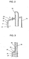
- Fig. 2 is a sectional view taken along the line A - A of Fig. 1.
- Fig. 3 is a sectional view taken along the line B - B of Fig. 1.
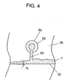
- Fig. 4 is a front view of the suction muffler at the part shown in Fig. 3.
- Fig. 5 is a sectional view of the hermetic electric compressor in accordance with the exemplary embodiment.
- Closed vessel 1 includes stator 3, electric element 5 formed of rotor 4, and compressing element 6 driven by electric element 5.
- Oil reservoir 36 is disposed in the lower part of closed vessel 1 and stores oil 7.
- Crankshaft 8 has spindle 9 pressed and fitted to rotor 4 and eccentric part 10 formed eccentrically to spindle 9.
- Oil pump 12 formed of hole 11 having tilt with respect to the shaft core of spindle 9 is disposed in spindle 9 so as to open in oil 7 in oil reservoir 36.
- Communication hole 13 is disposed in eccentric part 10. One end of communication hole 13 opens at the upper end of eccentric part 10, and the other end communicates with oil pump 12 via oil groove 14 formed in the outer periphery of spindle 9.
- Cylinder block 15 has substantially cylindrical compression chamber 16 and bearing 17 for pivoting spindle 9, and is formed over electric element 5. Piston 18 is inserted into compression chamber 16, and is coupled to eccentric part 10 through connecting rod 19 as a coupling means.
- Valve plate 20 seals an end surface of compression chamber 16, and has a discharge valve (not shown) and a suction valve (not shown).
- Head 23 having a high pressure chamber 21 communicating with the discharge valve is fixed on the opposite side to compression chamber 16 with respect to valve plate 20.
- Suction tube 24 is fixed to closed vessel 1 and connected to the low pressure side (not shown) of a freezing cycle so that refrigerant gas (not shown) is guided into closed vessel 1.
- suction muffler 25 is disposed under cylinder block 15, and grappled and fixed by valve plate 20 and head 23.
- One end of suction muffler 25 communicates with compression chamber 16 via the suction valve of valve plate 20.
- the other end of suction muffler 25 forms sound absorbing space 27 communicating with opening 26 formed near suction tube 24 disposed in closed vessel 1.
- Fig. 1 is a perspective view of entire suction muffler 25
- Fig. 2 is a sectional view taken along the line A - A of Fig. 1
- Fig. 3 is a sectional view taken along the line B - B of Fig. 1.
- Suction muffler 25 has a box body shape as a whole, and is made of engineering plastics such as polybutylene terephthalate (PBT).
- Oil suction port 28 for connecting the internal space working as sound absorbing space 27 of suction muffler 25 to the outside of suction muffler 25 is disposed in the side part of suction muffler 25. The outer surface of the side part having oil suction port 28 faces the inside of closed vessel 1.
- Upper surface part 29 of suction muffler 25 is set thicker than the other surface parts forming suction muffler 25, and tilts by tilting angle ⁇ 1 toward side surface 30 having oil suction port 28.
- Tilting angle ⁇ 1 is set at an angle exceeding 5°. This 5° is an upper limit on the installation angle of a general hermetic electric compressor.
- the upper limit on the installation angle of the general hermetic electric compressor means an allowable angle between the compressor and the horizontal plane of the floor when a body of an electric refrigerator, an air conditioner, or a vending machine having the built-in the compressor is installed.
- Step part 31 is formed below oil suction port 28, and oil sump 32 is disposed on the upper surface of step part 31.
- Oil sump 32 has tilting angle ⁇ 2 on the surface of suction muffler 25 facing to the inside of the closed vessel, namely on surface 30 facing to the electric element side, and tilts toward oil suction port 28 by tilting angle ⁇ 2 .
- Tilting angle ⁇ 2 exceeds 5° as the upper limit on the installation angle of the general hermetic electric compressor.
- Communication groove 33 having a substantially V-shaped cross section connects oil sump 32 to oil suction port 28.
- the depth of communication groove 33 is set at 0.15 mm, and the diameter of oil suction port 28 is set at 0.5 mm.
- Suction communication part 34 that opens in suction chamber 22 of head 23 shown in Fig. 5 is disposed over suction muffler 25.
- Oil suction port 28 has a chamfer 35.
- Rotor 4 of electric element 5 rotates crankshaft 9, and motion of eccentric part 10 is transmitted to piston 18 via connecting rod 19.
- Piston 18 reciprocates in compression chamber 16, refrigerant gas guided into closed vessel 1 through suction tube 24 is thus sucked from opening 26 of suction muffler 25 and continuously compressed in compression chamber 16.
- crankshaft 9 a centrifugal force is exerted on oil 7 through hole 11 tilting with respect to the shaft core in oil pump 12. Oil 7 is then sucked from oil reservoir 36, guided upwardly from oil groove 14, and sprayed from the upper end of eccentric part 10 into closed vessel 1 through communication hole 13.
- Oil 7 is sprayed also to cylinder block 15, drops from cylinder block 15 onto the upper surface 29 of suction muffler 25, and drops to the bottom of closed vessel 1 on the surface of suction muffler 25. At this time, oil 7 flowing on surface 30 of suction muffler 25 on the electric element 5 side is sucked into sound absorbing space 27 through oil suction port 28, is sucked into compression chamber 16 through suction communication part 34, and provides lubrication and sealing between piston 18 and the inside of compression chamber 16.
- upper surface 29 of suction muffler 25 tilts toward surface 30 on the electric element 5 side, and tilting angle ⁇ 1 is set at not less than 5°, namely the upper limit on the installation angle of the general hermetic electric compressor. Therefore, regardless of an installation attitude of the hermetic electric compressor, almost all of oil 7 dropping onto the upper surface 29 of suction muffler 25 flows to surface 30 having oil suction port 28 on the electric element 5 side. As shown in Fig. 4, a certain amount of oil 7 is stored in oil sump 32 disposed on step part 31 below oil suction port 28, and oil 7 flows to oil suction port 28 due to surface tension thereof and is sucked into sound absorbing space 27.
- oil sump 32 also tilts toward oil suction port 28 by tilting angle ⁇ 2 exceeding 5° as the upper limit on the installation angle of the general hermetic electric compressor, oil 7 is stably stored under oil suction port 28 regardless of the installation attitude of the hermetic electric compressor.
- the amount of oil sucked into sound absorbing space 27 can be therefore kept substantially constant.
- Flow rate of the oil sucked into sound absorbing space 27 can be increased by connecting oil sump 32 to oil suction port 28 through communication groove 33, so that the oil can be further certainly sucked.
- Changing the depth of communication groove 33 and the diameter of oil suction port 28 can change flow resistance of the oil, so that the amount of the oil sucked into sound absorbing space 27 can be controlled. Since the depth of communication groove 33 is set at 0.15 mm and the diameter of oil suction port 28 is set at 0.5 mm, 15 mm 3 of oil is sucked per hour. When the suction rate is less than 3 mm 3 /hour, abrasion of the sliding part can occur because of insufficient lubrication between piston 18, and the inside of compression chamber 16 and the freezing performance can decrease because of incomplete sealing.
- the suction rate exceeds 30 mm 3 /hour, power consumption can increase because the sucked oil is compressed to increase compression work or because a large amount of oil is discharged to a freezing cycle to decrease heat exchange efficiency of the freezing cycle. Therefore, it is preferable to set the suction rate of oil in the range of 3 mm 3 /hour to 30 mm 3 /hour.
- suction muffler 25 is made of engineering plastics such as PBT having low thermal conductivity, thereby moderating heating of the sucked refrigerant gas by oil 7 heated by compression heat of cylinder block 15. Glass fiber is mixed to engineering plastics by about 15%, thereby increasing the heat resistance and mechanical strength. For further decreasing the heating of the sucked gas, a method of mixing no glass fiber into the plastics is used. At this time, the thermal conductivity can be further decreased by 30%.
- Noise in sound absorbing space 27 partially leaks from oil suction port 28 and is transmitted, but, in the present invention, noise transmission toward closed vessel 1 is suppressed and noise transmission to the outside through closed vessel 1 can be reduced. That is because the opening of oil suction port 28 is directed to surface 30 on the electric element 5 side, namely to the opposite side to the outside of closed vessel 1.
- oil stored in the lower part of a closed vessel having a compressing element is sprayed and supplied into the closed vessel in response to rotation of an electric element.
- the oil is then dropped onto a suction muffler that is disposed in a refrigerant suction part of the compressing element and absorbs sounds, and stably supplied to a compression chamber through an oil suction port disposed in the suction muffler.
- the oil suction port is opened toward the inside of the closed vessel, so that noise transmitted from the oil suction port can be reduced.
- an hermetic electric compressor can be realized where the oil is stably supplied to the compression chamber, lubrication of the sliding part of the compression chamber is smoothened, and a stable operation with a low noise level is allowed.
Landscapes
- Engineering & Computer Science (AREA)
- Mechanical Engineering (AREA)
- General Engineering & Computer Science (AREA)
- Compressor (AREA)
Description
- The present invention relates to an hermetic electric compressor used in an electric refrigerator, an air conditioner, or a vending machine.
- An hermetic electric compressor including an electric element and a compressing element in a closed vessel is widely used as a compressor employed in an electric refrigerator or an air conditioner. For example, an hermetic electric compressor having a structure shown in Fig. 6 is disclosed as a prior art in U.S. Patent No. 5,228,843.
- The conventional hermetic electric compressor will be hereinafter with reference to Fig. 6. The upside and downside of the hermetic electric compressor are determined with reference to the state where the compressor is installed in the normal attitude.
- Fig. 6 is a sectional view of the conventional hermetic electric compressor.
Closed vessel 201 includesstator 202,electric element 204 formed ofrotor 203, and compressingelement 205 driven byelectric element 204.Oil 207 is reserved in the lower part of closedvessel 201. Compressingelement 205 is then described in detail. Crankshaft 208 hasspindle 209 pressed and fitted torotor 203 andeccentric part 210 formed eccentrically tospindle 209.Oil pump 211 is disposed inspindle 209 so as to open inoil 207. One end ofcommunication hole 212 disposed ineccentric part 210 opens at the upper end ofeccentric part 210, and the other end communicates withoil pump 211 viaoil groove 213 formed in the outer periphery ofspindle 209.Cylinder block 214 has substantiallycylindrical compression chamber 215 and bearing 216 for pivotingspindle 209, and is formed overelectric element 204. Piston 217 is inserted intocompression chamber 215, and is coupled toeccentric part 210 through coupling means 218.Valve plate 219 having a compressing valve and a suction valve is disposed on an end surface ofcompression chamber 215, andhead 220 having a space partitioned to a discharge side and a suction side is disposed outsidevalve plate 219.Suction tube 221 is fixed to closedvessel 201 and connected to the low pressure side (not shown) of a freezing cycle so that refrigerant gas (not shown) is guided into closedvessel 201.Suction muffler 222 is disposed undercylinder block 214, and is grappled and hence fixed byvalve plate 219 andhead 220. One end ofsuction muffler 222 communicates with the suction side ofhead 220 and communicates withcompression chamber 215 through the suction valve ofvalve plate 219. The other end ofsuction muffler 222 formssound absorbing space 224 communicating with opening 223 formed nearsuction tube 221 disposed in closedvessel 201. - A series of operations in the structure discussed above are described.
Rotor 203 ofelectric element 204 rotatescrankshaft 208. Motion ofeccentric part 210 is transmitted topiston 217 via coupling means 218, thereby reciprocatingpiston 217 incompression chamber 215. Refrigerant gas guided into closedvessel 201 throughsuction tube 221 is sucked from opening 223 ofsuction muffler 222, and is continuously compressed incompression chamber 215. By rotatingcrankshaft 208,oil 207 is sucked byoil pump 211, is guided upwardly fromoil groove 213, passes throughcommunication hole 212, and is sprayed from the upper end ofeccentric part 210 into closedvessel 201. Sprayedoil 207 is sucked together with refrigerant gas from opening 223 ofsuction muffler 222, and provides lubrication and sealing betweenpiston 217 and the inside ofcompression chamber 215. - However, the hermetic electric compressor has the following problems. In the conventional hermetic electric compressor,
oil 207 sprayed into closedvessel 201 is indirectly sucked together with refrigerant gas from opening 223, so that an amount ofoil 207 sucked intocompression chamber 215 is widely dispersed by sprayingoil 207. Therefore, when the amount ofoil 207 is small, sufficient lubrication betweenpiston 217 and the inside ofcompression chamber 215 is not obtained to generate abrasion of a sliding part, and sealing is incomplete to decrease a freezing capacity. - Reference may be made to GB-A-2315523 which describes a compressor comprising a prime mover driving a crank. A piston is reciprocated within a Cylinder block by the crank. A cylinder head includes an inlet chamber and an outlet chamber. Refrigerant is supplied to the cylinder block, to be compressed by the action of the piston, from a muffler via a conduit and the inlet chamber. In order to reduce the transfer of heat to the refrigerant before compression, the inlet chamber is lined with material of low thermal conductivity and the conduit is also formed of material having low thermal conductivity. Manufacture may be simplified by forming the lining and the conduit as a single unit. Reference may also be made to US-A-5201640, JP-A-2000 274359, JP-U-52 065910, US-A-4569639, JP-U-60 139085, and JP-U-52 009108.
- The present invention addresses the conventional problems discussed above, and aims to provide an hermetic electric compressor capable of stably supplying the right amount of oil into a compression chamber.
- The present invention is defined in the claims.
- In a preferred embodiment of the invention, an hermetic electric compressor has the following structure. The hermetic electric compressor has a closed vessel connected at least to a suction refrigerant pipe and a discharge refrigerant pipe. The compressor also has, in the closed vessel, an electric element, a compressing element that is disposed over the electric element and driven by the electric element, and an oil reservoir for storing oil under the electric element. The compressor also has an oil supply mechanism and a suction muffler. The oil supply mechanism supplies the oil from the oil reservoir to the compressing element in the closed vessel. The suction muffler communicates with a refrigerant suction part for sucking a refrigerant into the compressing element and is formed of a box body having a predetermined spatial volume. The suction muffler is positioned below the position where the oil is supplied into the closed vessel, and the box body has at least one oil suction port used for sucking a predetermined amount of oil as it flows down from the position where it is supplied into the closed vessel.
- This structure allows the oil supplied to the compressing element in the closed vessel to be stably sucked through the oil suction port formed in the box body of the suction muffler. Therefore, the oil can be stably supplied into a compression chamber, thereby smoothening lubrication on a sliding part.
- Additionally, at least the upper surface of the box body is positioned under the position where the oil is supplied into the closed vessel. The oil sprayed to the upper part of the box body can thus be received and collected by the upper part of the box body, and hence the collected oil can be stably sucked from the oil suction port to the compression chamber through the suction muffler.
- The oil suction port is formed in a surface of the suction muffler inside the closed vessel, so that noise transmitted from the oil suction port can be reduced.
- Additionally, a side surface of the box body is provided with a step part projecting outwardly, and the upper surface of the box body tilts by at least the installation angle or more of the hermetic electric compressor. The step part tilts downwardly, and toward the oil suction port, the tilting angle of the step part is at least the installation angle or more of the hermetic electric compressor. A communication groove for connecting the step part to the oil suction port is disposed.
- Thanks to the structure, the oil supplied to compressing element in the closed vessel drops to the upper surface of the box body of the suction muffler, flows down on the upper surface, then flows down on the step part, and is stably sucked into the oil suction port through the communication groove. The oil supply to the compression chamber is further stabilized.
-
- Fig. 1 is a perspective view of a suction muffler of an hermetic electric compressor in accordance with an exemplary embodiment of the present invention.
- Fig. 2 is a sectional view taken along the line A - A of Fig. 1.
- Fig. 3 is a sectional view taken along the line B - B of Fig. 1.
- Fig. 4 is a front view of the suction muffler at the part shown in Fig. 3.
- Fig. 5 is a sectional view of the hermetic electric compressor in accordance with the exemplary embodiment of the present invention.
- Fig. 6 is a sectional view of a conventional hermetic electric compressor.
- An exemplary embodiment of the present invention will be described hereinafter with reference to the drawings.
- Fig. 1 is a perspective view of a suction muffler of an hermetic electric compressor in accordance with the exemplary embodiment. Fig. 2 is a sectional view taken along the line A - A of Fig. 1. Fig. 3 is a sectional view taken along the line B - B of Fig. 1. Fig. 4 is a front view of the suction muffler at the part shown in Fig. 3. Fig. 5 is a sectional view of the hermetic electric compressor in accordance with the exemplary embodiment.
- A structure of the hermetic electric compressor of the exemplary embodiment is described with reference to Fig. 5. Closed vessel 1 includes
stator 3,electric element 5 formed ofrotor 4, and compressingelement 6 driven byelectric element 5.Oil reservoir 36 is disposed in the lower part of closed vessel 1 and storesoil 7. - Compressing
element 6 is described in detail.Crankshaft 8 hasspindle 9 pressed and fitted torotor 4 andeccentric part 10 formed eccentrically tospindle 9.Oil pump 12 formed ofhole 11 having tilt with respect to the shaft core ofspindle 9 is disposed inspindle 9 so as to open inoil 7 inoil reservoir 36.Communication hole 13 is disposed ineccentric part 10. One end ofcommunication hole 13 opens at the upper end ofeccentric part 10, and the other end communicates withoil pump 12 viaoil groove 14 formed in the outer periphery ofspindle 9.Cylinder block 15 has substantiallycylindrical compression chamber 16 andbearing 17 for pivotingspindle 9, and is formed overelectric element 5.Piston 18 is inserted intocompression chamber 16, and is coupled toeccentric part 10 through connectingrod 19 as a coupling means.Valve plate 20 seals an end surface ofcompression chamber 16, and has a discharge valve (not shown) and a suction valve (not shown).Head 23 having ahigh pressure chamber 21 communicating with the discharge valve is fixed on the opposite side tocompression chamber 16 with respect tovalve plate 20.Suction tube 24 is fixed to closed vessel 1 and connected to the low pressure side (not shown) of a freezing cycle so that refrigerant gas (not shown) is guided into closed vessel 1. - In Fig. 5,
suction muffler 25 is disposed undercylinder block 15, and grappled and fixed byvalve plate 20 andhead 23. One end ofsuction muffler 25 communicates withcompression chamber 16 via the suction valve ofvalve plate 20. The other end ofsuction muffler 25 forms sound absorbingspace 27 communicating with opening 26 formed nearsuction tube 24 disposed in closed vessel 1. - Fig. 1 is a perspective view of
entire suction muffler 25, Fig. 2 is a sectional view taken along the line A - A of Fig. 1, and Fig. 3 is a sectional view taken along the line B - B of Fig. 1.Suction muffler 25 has a box body shape as a whole, and is made of engineering plastics such as polybutylene terephthalate (PBT).Oil suction port 28 for connecting the internal space working assound absorbing space 27 ofsuction muffler 25 to the outside ofsuction muffler 25 is disposed in the side part ofsuction muffler 25. The outer surface of the side part havingoil suction port 28 faces the inside of closed vessel 1.Upper surface part 29 ofsuction muffler 25 is set thicker than the other surface parts formingsuction muffler 25, and tilts by tilting angle θ1 towardside surface 30 havingoil suction port 28. Tilting angle θ1 is set at an angle exceeding 5°. This 5° is an upper limit on the installation angle of a general hermetic electric compressor. The upper limit on the installation angle of the general hermetic electric compressor means an allowable angle between the compressor and the horizontal plane of the floor when a body of an electric refrigerator, an air conditioner, or a vending machine having the built-in the compressor is installed. Steppart 31 is formed belowoil suction port 28, andoil sump 32 is disposed on the upper surface ofstep part 31.Oil sump 32 has tilting angle θ2 on the surface ofsuction muffler 25 facing to the inside of the closed vessel, namely onsurface 30 facing to the electric element side, and tilts towardoil suction port 28 by tilting angle θ2. Tilting angle θ2 exceeds 5° as the upper limit on the installation angle of the general hermetic electric compressor.Communication groove 33 having a substantially V-shaped cross section connectsoil sump 32 tooil suction port 28. The depth ofcommunication groove 33 is set at 0.15 mm, and the diameter ofoil suction port 28 is set at 0.5 mm.Suction communication part 34 that opens in suction chamber 22 ofhead 23 shown in Fig. 5 is disposed oversuction muffler 25.Oil suction port 28 has achamfer 35. - Operations of the hermetic electric compressor having the structure discussed above are hereinafter described.
Rotor 4 ofelectric element 5 rotatescrankshaft 9, and motion ofeccentric part 10 is transmitted topiston 18 via connectingrod 19.Piston 18 reciprocates incompression chamber 16, refrigerant gas guided into closed vessel 1 throughsuction tube 24 is thus sucked from opening 26 ofsuction muffler 25 and continuously compressed incompression chamber 16. By rotating,crankshaft 9, a centrifugal force is exerted onoil 7 throughhole 11 tilting with respect to the shaft core inoil pump 12.Oil 7 is then sucked fromoil reservoir 36, guided upwardly fromoil groove 14, and sprayed from the upper end ofeccentric part 10 into closed vessel 1 throughcommunication hole 13.Oil 7 is sprayed also tocylinder block 15, drops fromcylinder block 15 onto theupper surface 29 ofsuction muffler 25, and drops to the bottom of closed vessel 1 on the surface ofsuction muffler 25. At this time,oil 7 flowing onsurface 30 ofsuction muffler 25 on theelectric element 5 side is sucked intosound absorbing space 27 throughoil suction port 28, is sucked intocompression chamber 16 throughsuction communication part 34, and provides lubrication and sealing betweenpiston 18 and the inside ofcompression chamber 16. - In the present invention, as discussed above,
upper surface 29 ofsuction muffler 25 tilts towardsurface 30 on theelectric element 5 side, and tilting angle θ1 is set at not less than 5°, namely the upper limit on the installation angle of the general hermetic electric compressor. Therefore, regardless of an installation attitude of the hermetic electric compressor, almost all ofoil 7 dropping onto theupper surface 29 ofsuction muffler 25 flows to surface 30 havingoil suction port 28 on theelectric element 5 side. As shown in Fig. 4, a certain amount ofoil 7 is stored inoil sump 32 disposed onstep part 31 belowoil suction port 28, andoil 7 flows tooil suction port 28 due to surface tension thereof and is sucked intosound absorbing space 27. At this time, sinceoil sump 32 also tilts towardoil suction port 28 by tilting angle θ2 exceeding 5° as the upper limit on the installation angle of the general hermetic electric compressor,oil 7 is stably stored underoil suction port 28 regardless of the installation attitude of the hermetic electric compressor. The amount of oil sucked intosound absorbing space 27 can be therefore kept substantially constant. - Flow rate of the oil sucked into
sound absorbing space 27 can be increased by connectingoil sump 32 tooil suction port 28 throughcommunication groove 33, so that the oil can be further certainly sucked. - Changing the depth of
communication groove 33 and the diameter ofoil suction port 28 can change flow resistance of the oil, so that the amount of the oil sucked intosound absorbing space 27 can be controlled. Since the depth ofcommunication groove 33 is set at 0.15 mm and the diameter ofoil suction port 28 is set at 0.5 mm, 15 mm3 of oil is sucked per hour. When the suction rate is less than 3 mm3/hour, abrasion of the sliding part can occur because of insufficient lubrication betweenpiston 18, and the inside ofcompression chamber 16 and the freezing performance can decrease because of incomplete sealing. - When the suction rate exceeds 30 mm3/hour, power consumption can increase because the sucked oil is compressed to increase compression work or because a large amount of oil is discharged to a freezing cycle to decrease heat exchange efficiency of the freezing cycle. Therefore, it is preferable to set the suction rate of oil in the range of 3 mm3/hour to 30 mm3/hour.
-
Oil 7 dropping onto the upper surface 298 ofsuction muffler 25 fromcylinder block 15 is heated by compression heat ofcylinder block 15, the heat then transfers on the surface ofsuction muffler 25 and heats the sucked refrigerant gas insound absorbing space 27. It is known that heating the sucked refrigerant gas decreases volume efficiency of the compressor. However, in the present invention,suction muffler 25 is made of engineering plastics such as PBT having low thermal conductivity, thereby moderating heating of the sucked refrigerant gas byoil 7 heated by compression heat ofcylinder block 15. Glass fiber is mixed to engineering plastics by about 15%, thereby increasing the heat resistance and mechanical strength. For further decreasing the heating of the sucked gas, a method of mixing no glass fiber into the plastics is used. At this time, the thermal conductivity can be further decreased by 30%. - Since the thickness of
upper surface 29 ofsuction muffler 25 that directly receivesoil 7 having especially high temperature is set larger than that of the other surfaces constitutingsuction muffler 25, heating of the sucked refrigerant gas insound absorbing space 27 is further suppressed. - Noise in
sound absorbing space 27 partially leaks fromoil suction port 28 and is transmitted, but, in the present invention, noise transmission toward closed vessel 1 is suppressed and noise transmission to the outside through closed vessel 1 can be reduced. That is because the opening ofoil suction port 28 is directed to surface 30 on theelectric element 5 side, namely to the opposite side to the outside of closed vessel 1. - The operations by the structure discussed above produce the advantage regardless of kinds of a refrigerant and oil combined with it.
- In the present invention, as discussed above, oil stored in the lower part of a closed vessel having a compressing element is sprayed and supplied into the closed vessel in response to rotation of an electric element. The oil is then dropped onto a suction muffler that is disposed in a refrigerant suction part of the compressing element and absorbs sounds, and stably supplied to a compression chamber through an oil suction port disposed in the suction muffler. The oil suction port is opened toward the inside of the closed vessel, so that noise transmitted from the oil suction port can be reduced.
- Therefore, an hermetic electric compressor can be realized where the oil is stably supplied to the compression chamber, lubrication of the sliding part of the compression chamber is smoothened, and a stable operation with a low noise level is allowed.
-
- 1
- Closed vessel
- 3
- Stator
- 4
- Rotor
- 5
- Electric element
- 6
- Compressing element
- 7
- Oil
- 8
- Crankshaft
- 9
- Spindle
- 10
- Eccentric part
- 11
- Hole
- 12
- Oil pump
- 13
- Communication hole
- 14
- Oil groove
- 15
- Cylinder block
- 16
- Compression chamber
- 17
- Bearing
- 18
- Piston
- 19
- Connecting rod
- 20
- Valve plate
- 21
- High pressure chamber
- 23
- Head
- 24
- Suction tube
- 25
- Suction muffler
- 26
- Opening
- 27
- Sound absorbing space
- 28
- Oil suction port
- 29
- Upper surface part
- 30
- Side surface
- 31
- Step part
- 32
- Oil sump
- 33
- Communication groove
- 34
- Suction communication part
- 35
- Chamfer
- 36
- Oil reservoir
Claims (15)
- An hermetic electric compressor comprising:a closed vessel (1) connected at least to a suction refrigerant pipe (24) and a discharge refrigerant pipe;an electric element (5) disposed in said closed vessel;a compressing element (6) that is disposed over said electric element in said closed vessel and is driven by said electric element;an oil reservoir (36) for storing oil under said electric element in said closed vessel;an oil supply mechanism (12, 13) for spraying and supplying the oil from said oil reservoir to an upper part of said compressing element in said closed vessel; anda suction muffler (25) that communicates with a refrigerant suction part for sucking a refrigerant into said compressing element and is formed of a box body having a predetermined spatial volume,wherein
said suction muffler (25) is separated from said compressing element (6), said suction muffler being made from a material having a low thermal conductivity, and positioned below a position where the oil supply mechanism (12, 13) sprays and supplies the oil into said closed vessel, and
characterised in that the box body has at least one oil suction port (28) used for sucking, through the surface of the box body, a predetermined amount of oil sprayed and supplied in the upper portion of said closed vessel, as said oil flows down from said upper portion to said oil reservoir (36). - An hermetic electric compressor according to claim 1,
wherein the oil suction port (28) is disposed in a surface of said suction muffler (25) on the inside of said closed vessel (1). - An hermetic electric compressor according to claim 1 or claim 2,
wherein an upper surface (29) of the box body tilts downwardly toward the surface (30) having the oil suction port (28). - An hermetic electric compressor according to claim 3,
wherein a tilting angle (θ1) of the upper surface (29) of the box body is at least not less than an installation angle of said hermetic electric compressor. - An hermetic electric compressor according to claim 1,
wherein a side surface (30) of the box body has a step part (31, 32) projecting outwardly from the box body. - An hermetic electric compressor according to claim 5,
wherein the step part (31, 32) tilts downwardly toward the oil suction port (28). - An hermetic electric compressor according to claim 6,
wherein a tilting angle (θ2) of the step part (31, 32) is at least not less than an installation angle of said hermetic electric compressor. - An hermetic electric compressor according to one of claim 5 to claim 7,
wherein a communication groove (33) for connecting the step part (31, 32) to the oil suction port (28) is provided. - An hermetic electric compressor according to claim 8,
wherein an amount of oil flowing through the oil suction port (28) and the communication groove (33) is in a range of 3 mm3/hour to 30 mm3/hour. - An hermetic electric compressor according to claim 1,
wherein said suction muffler(25) is made of plastic material. - An hermetic electric compressor according to claim 10,
wherein the plastic material contains no glass fiber. - An hermetic electric compressor according to claim 1 or claim 2,
wherein an upper surface part (30) of the box body of said suction muffler (25) is thicker than the other parts. - An hermetic electric compressor according to claim 1, wherein:said electric element (5) comprises a stator(3) on an outside of said electric element and a rotor (4) on an inside of said electric element,said electric element (5) comprises a main shaft (9) inserted into and fixed to a rotation center of the rotor and an eccentric shaft (10) that is connected to the main shaft (9), is eccentric from a shaft center of the main shaft, and is connected to the compressing element,said suction muffler (25) is grappled and fixed by a valve plate (20) and a head (23), one end of said suction muffler (25) communicating with the compression chamber (16) via a suction valve of the valve plate (20), the other end of said suction muffler (25) communicating with the inside of said closed vessel via an opening; anda rotation of the eccentric shaft (10) is converted to a reciprocating motion of a piston (18) by rotation of the rotor (4), thereby compressing the refrigerant.
- An hermetic electric compressor according to claim 13,
wherein an oil passage (11) tilting with respect to the shaft center is disposed at least in the main shaft (9). - An hermetic electric compressor according to claim 13,
wherein the oil stored in the oil reservoir(36) is sprayed and supplied from the eccentric shaft (10) into the closed vessel by rotation of said electric element (10).
Applications Claiming Priority (3)
| Application Number | Priority Date | Filing Date | Title |
|---|---|---|---|
| JP2001136033 | 2001-05-07 | ||
| JP2001136033A JP4682441B2 (en) | 2001-05-07 | 2001-05-07 | Hermetic electric compressor |
| PCT/JP2002/004294 WO2002090774A1 (en) | 2001-05-07 | 2002-04-26 | Hermetic electric compressor |
Publications (3)
| Publication Number | Publication Date |
|---|---|
| EP1384890A1 EP1384890A1 (en) | 2004-01-28 |
| EP1384890A4 EP1384890A4 (en) | 2005-06-15 |
| EP1384890B1 true EP1384890B1 (en) | 2006-09-20 |
Family
ID=18983400
Family Applications (1)
| Application Number | Title | Priority Date | Filing Date |
|---|---|---|---|
| EP02722880A Expired - Lifetime EP1384890B1 (en) | 2001-05-07 | 2002-04-26 | Hermetic electric compressor |
Country Status (9)
| Country | Link |
|---|---|
| US (1) | US7134847B2 (en) |
| EP (1) | EP1384890B1 (en) |
| JP (1) | JP4682441B2 (en) |
| KR (1) | KR100567494B1 (en) |
| CN (1) | CN1265090C (en) |
| BR (1) | BR0209281A (en) |
| DE (1) | DE60214841T2 (en) |
| MX (1) | MXPA03007396A (en) |
| WO (1) | WO2002090774A1 (en) |
Families Citing this family (13)
| Publication number | Priority date | Publication date | Assignee | Title |
|---|---|---|---|---|
| JP2005133707A (en) * | 2003-10-10 | 2005-05-26 | Matsushita Electric Ind Co Ltd | Hermetic compressor |
| JP4429769B2 (en) * | 2004-03-16 | 2010-03-10 | パナソニック株式会社 | Hermetic compressor |
| DE102004050844B4 (en) * | 2004-10-18 | 2009-05-07 | Danfoss Compressors Gmbh | Piston compressor-cylinder arrangement, in particular for hermetically sealed refrigerant compressor |
| JP4569404B2 (en) * | 2005-07-07 | 2010-10-27 | パナソニック株式会社 | Compressor |
| CN101541932A (en) * | 2007-05-10 | 2009-09-23 | 松下电器产业株式会社 | Hermetic compressor and refrigeration system |
| JP4900151B2 (en) * | 2007-09-18 | 2012-03-21 | パナソニック株式会社 | Refrigerant compressor |
| US8235683B2 (en) * | 2007-12-06 | 2012-08-07 | Panasonic Corporation | Hermetic compressor |
| KR101454246B1 (en) * | 2009-01-14 | 2014-10-23 | 엘지전자 주식회사 | Reciprocating compressor |
| JP5463275B2 (en) * | 2010-12-15 | 2014-04-09 | 日立アプライアンス株式会社 | Hermetic compressor and refrigerator equipped with the same |
| JP5945845B2 (en) * | 2011-04-11 | 2016-07-05 | パナソニックIpマネジメント株式会社 | Hermetic compressor |
| BR102013019311B1 (en) * | 2013-07-30 | 2021-10-13 | Embraco Indústria De Compressores E Soluções Em Refrigeração Ltda | ACOUSTIC ATTENUATOR DEVICE FOR COMPRESSORS |
| SG10201401663VA (en) * | 2014-04-21 | 2015-11-27 | Panasonic Corp | Compressor Or Suction Muffler |
| CN111963409B (en) * | 2020-08-19 | 2022-08-30 | 江苏白雪制冷机电有限公司 | Air suction silencer |
Family Cites Families (15)
| Publication number | Priority date | Publication date | Assignee | Title |
|---|---|---|---|---|
| JPS529108U (en) * | 1975-07-09 | 1977-01-22 | ||
| JPS529108A (en) | 1975-07-14 | 1977-01-24 | Matsushita Electric Ind Co Ltd | Pump unit for shallow well |
| JPS5265910U (en) * | 1975-11-12 | 1977-05-16 | ||
| JPS5265910A (en) | 1975-11-27 | 1977-05-31 | Kondo Yoshitsugu | Vibrationnfree and noiseless pile driving method and apparatus therefor |
| JPS52139407A (en) | 1976-05-17 | 1977-11-21 | Fujitsu Ltd | Medium mounting and automatic centering device |
| US4569639A (en) * | 1982-05-03 | 1986-02-11 | Tecumseh Products Company | Oil distribution system for a compressor |
| JPS60139085A (en) | 1983-12-27 | 1985-07-23 | Hitachi Ltd | Radiation resistant color ITV camera |
| JPS60139085U (en) * | 1984-02-24 | 1985-09-13 | 株式会社東芝 | hermetic compressor |
| RO100617B1 (en) * | 1989-10-06 | 1993-02-28 | îNTREPRINDEREA DE FRIGIDERE | Compressor for household refrigerators |
| BR9102288A (en) * | 1991-05-28 | 1993-01-05 | Brasileira S A Embraco Empresa | SUCTION DIFFERENT SET FOR HERMETIC COMPRESSOR |
| GB2315523B (en) | 1994-04-29 | 1998-09-23 | Samsung Electronics Co Ltd | Compressor |
| KR100207792B1 (en) * | 1997-02-24 | 1999-07-15 | 윤종용 | A close typed compressor |
| JP2000274359A (en) * | 1999-03-25 | 2000-10-03 | Matsushita Refrig Co Ltd | Refrigerant compressor and refrigerating cycle system |
| US6524080B2 (en) * | 2000-04-11 | 2003-02-25 | R. K. Dewan & Co. | Hermetically sealed compressors |
| JP4492032B2 (en) * | 2003-03-27 | 2010-06-30 | パナソニック株式会社 | Hermetic compressor |
-
2001
- 2001-05-07 JP JP2001136033A patent/JP4682441B2/en not_active Expired - Fee Related
-
2002
- 2002-04-26 EP EP02722880A patent/EP1384890B1/en not_active Expired - Lifetime
- 2002-04-26 MX MXPA03007396A patent/MXPA03007396A/en unknown
- 2002-04-26 KR KR1020037014470A patent/KR100567494B1/en not_active Expired - Fee Related
- 2002-04-26 US US10/467,522 patent/US7134847B2/en not_active Expired - Lifetime
- 2002-04-26 CN CNB028094492A patent/CN1265090C/en not_active Expired - Fee Related
- 2002-04-26 BR BR0209281-6A patent/BR0209281A/en not_active IP Right Cessation
- 2002-04-26 DE DE60214841T patent/DE60214841T2/en not_active Expired - Lifetime
- 2002-04-26 WO PCT/JP2002/004294 patent/WO2002090774A1/en not_active Ceased
Also Published As
| Publication number | Publication date |
|---|---|
| EP1384890A4 (en) | 2005-06-15 |
| US20040120832A1 (en) | 2004-06-24 |
| MXPA03007396A (en) | 2004-11-12 |
| US7134847B2 (en) | 2006-11-14 |
| DE60214841T2 (en) | 2007-09-20 |
| WO2002090774A1 (en) | 2002-11-14 |
| DE60214841D1 (en) | 2006-11-02 |
| KR20030090805A (en) | 2003-11-28 |
| EP1384890A1 (en) | 2004-01-28 |
| CN1265090C (en) | 2006-07-19 |
| CN1507539A (en) | 2004-06-23 |
| JP2002332965A (en) | 2002-11-22 |
| BR0209281A (en) | 2004-07-13 |
| KR100567494B1 (en) | 2006-04-03 |
| JP4682441B2 (en) | 2011-05-11 |
Similar Documents
| Publication | Publication Date | Title |
|---|---|---|
| US7134847B2 (en) | Hermetic electric compressor having a suction muffler | |
| EP2397693B1 (en) | Sealed compressor and refrigeration device | |
| KR100857964B1 (en) | Hermetic compressor | |
| CA2069208C (en) | Refrigeration compressor having a contoured piston | |
| US5888055A (en) | Connection between a refrigerant pipe and a suction muffler of a hermetic reciprocating compressor | |
| EP1864020B1 (en) | Hermetic compressor | |
| KR101451472B1 (en) | Variable displacement swash plate type compressor | |
| KR101753403B1 (en) | Compressor | |
| CN214403986U (en) | Oil circuit structure, horizontal scroll compressor and refrigeration equipment | |
| KR101843756B1 (en) | Variable displacement swash plate type compressor | |
| EP1957796B1 (en) | A compressor | |
| KR100918669B1 (en) | compressor | |
| CN2913716Y (en) | Crankshaft of sealed rotary compressor | |
| JP2003293953A (en) | Reciprocating hermetic electric compressor | |
| KR20120090643A (en) | compressor | |
| JP2009203810A (en) | Hermetic compressor and refrigeration cycle device | |
| KR0126732Y1 (en) | Reciprocating compressor | |
| KR20020038001A (en) | Apparatus for feeding oil into cylinder of hermetic type compressor | |
| KR101309661B1 (en) | Hermetic compressor and refregerator comprising the same | |
| KR20000015397U (en) | Piston for Air Conditioning Compressor | |
| KR20020056272A (en) | An oil guiding structure of crankshaft for hermetic compressor | |
| JP2003328930A (en) | Compressor |
Legal Events
| Date | Code | Title | Description |
|---|---|---|---|
| PUAI | Public reference made under article 153(3) epc to a published international application that has entered the european phase |
Free format text: ORIGINAL CODE: 0009012 |
|
| 17P | Request for examination filed |
Effective date: 20031031 |
|
| AK | Designated contracting states |
Kind code of ref document: A1 Designated state(s): AT BE CH CY DE DK ES FI FR GB GR IE IT LI LU MC NL PT SE TR |
|
| A4 | Supplementary search report drawn up and despatched |
Effective date: 20050502 |
|
| GRAP | Despatch of communication of intention to grant a patent |
Free format text: ORIGINAL CODE: EPIDOSNIGR1 |
|
| GRAS | Grant fee paid |
Free format text: ORIGINAL CODE: EPIDOSNIGR3 |
|
| GRAA | (expected) grant |
Free format text: ORIGINAL CODE: 0009210 |
|
| AK | Designated contracting states |
Kind code of ref document: B1 Designated state(s): DE ES FR GB IT |
|
| PG25 | Lapsed in a contracting state [announced via postgrant information from national office to epo] |
Ref country code: IT Free format text: LAPSE BECAUSE OF FAILURE TO SUBMIT A TRANSLATION OF THE DESCRIPTION OR TO PAY THE FEE WITHIN THE PRESCRIBED TIME-LIMIT;WARNING: LAPSES OF ITALIAN PATENTS WITH EFFECTIVE DATE BEFORE 2007 MAY HAVE OCCURRED AT ANY TIME BEFORE 2007. THE CORRECT EFFECTIVE DATE MAY BE DIFFERENT FROM THE ONE RECORDED. Effective date: 20060920 |
|
| REG | Reference to a national code |
Ref country code: GB Ref legal event code: FG4D |
|
| REF | Corresponds to: |
Ref document number: 60214841 Country of ref document: DE Date of ref document: 20061102 Kind code of ref document: P |
|
| PG25 | Lapsed in a contracting state [announced via postgrant information from national office to epo] |
Ref country code: ES Free format text: LAPSE BECAUSE OF FAILURE TO SUBMIT A TRANSLATION OF THE DESCRIPTION OR TO PAY THE FEE WITHIN THE PRESCRIBED TIME-LIMIT Effective date: 20061231 |
|
| EN | Fr: translation not filed | ||
| PLBE | No opposition filed within time limit |
Free format text: ORIGINAL CODE: 0009261 |
|
| STAA | Information on the status of an ep patent application or granted ep patent |
Free format text: STATUS: NO OPPOSITION FILED WITHIN TIME LIMIT |
|
| 26N | No opposition filed |
Effective date: 20070621 |
|
| GBPC | Gb: european patent ceased through non-payment of renewal fee |
Effective date: 20070426 |
|
| PG25 | Lapsed in a contracting state [announced via postgrant information from national office to epo] |
Ref country code: FR Free format text: LAPSE BECAUSE OF FAILURE TO SUBMIT A TRANSLATION OF THE DESCRIPTION OR TO PAY THE FEE WITHIN THE PRESCRIBED TIME-LIMIT Effective date: 20070518 Ref country code: GB Free format text: LAPSE BECAUSE OF NON-PAYMENT OF DUE FEES Effective date: 20070426 |
|
| PG25 | Lapsed in a contracting state [announced via postgrant information from national office to epo] |
Ref country code: FR Free format text: LAPSE BECAUSE OF FAILURE TO SUBMIT A TRANSLATION OF THE DESCRIPTION OR TO PAY THE FEE WITHIN THE PRESCRIBED TIME-LIMIT Effective date: 20060920 |
|
| PGFP | Annual fee paid to national office [announced via postgrant information from national office to epo] |
Ref country code: IT Payment date: 20140415 Year of fee payment: 13 |
|
| PG25 | Lapsed in a contracting state [announced via postgrant information from national office to epo] |
Ref country code: IT Free format text: LAPSE BECAUSE OF NON-PAYMENT OF DUE FEES Effective date: 20150426 |
|
| REG | Reference to a national code |
Ref country code: DE Ref legal event code: R082 Ref document number: 60214841 Country of ref document: DE Representative=s name: TBK, DE Ref country code: DE Ref legal event code: R081 Ref document number: 60214841 Country of ref document: DE Owner name: PANASONIC APPLIANCES REFRIGERATION DEVICES SIN, SG Free format text: FORMER OWNER: PANASONIC CORPORATION, KADOMA-SHI, OSAKA, JP |
|
| PGFP | Annual fee paid to national office [announced via postgrant information from national office to epo] |
Ref country code: DE Payment date: 20200420 Year of fee payment: 19 |
|
| REG | Reference to a national code |
Ref country code: DE Ref legal event code: R119 Ref document number: 60214841 Country of ref document: DE |
|
| PG25 | Lapsed in a contracting state [announced via postgrant information from national office to epo] |
Ref country code: DE Free format text: LAPSE BECAUSE OF NON-PAYMENT OF DUE FEES Effective date: 20211103 |