EP1384866B1 - Exhaust gas cleaner for internal combustion engine - Google Patents
Exhaust gas cleaner for internal combustion engine Download PDFInfo
- Publication number
- EP1384866B1 EP1384866B1 EP02717090A EP02717090A EP1384866B1 EP 1384866 B1 EP1384866 B1 EP 1384866B1 EP 02717090 A EP02717090 A EP 02717090A EP 02717090 A EP02717090 A EP 02717090A EP 1384866 B1 EP1384866 B1 EP 1384866B1
- Authority
- EP
- European Patent Office
- Prior art keywords
- absorbing
- catalyst
- exhaust gas
- reduction catalyst
- absorbing reduction
- Prior art date
- Legal status (The legal status is an assumption and is not a legal conclusion. Google has not performed a legal analysis and makes no representation as to the accuracy of the status listed.)
- Expired - Lifetime
Links
- 238000002485 combustion reaction Methods 0.000 title claims abstract description 40
- 239000003054 catalyst Substances 0.000 claims abstract description 212
- 239000007789 gas Substances 0.000 claims abstract description 70
- QVGXLLKOCUKJST-UHFFFAOYSA-N atomic oxygen Chemical compound [O] QVGXLLKOCUKJST-UHFFFAOYSA-N 0.000 claims abstract description 56
- 239000001301 oxygen Substances 0.000 claims abstract description 56
- 229910052760 oxygen Inorganic materials 0.000 claims abstract description 56
- 239000000446 fuel Substances 0.000 claims description 45
- 238000011144 upstream manufacturing Methods 0.000 claims description 31
- 238000011084 recovery Methods 0.000 claims description 26
- 230000006866 deterioration Effects 0.000 claims description 25
- 238000000034 method Methods 0.000 claims description 20
- 230000003647 oxidation Effects 0.000 claims description 10
- 238000007254 oxidation reaction Methods 0.000 claims description 10
- 230000001590 oxidative effect Effects 0.000 claims description 3
- 230000015556 catabolic process Effects 0.000 abstract 1
- 238000006731 degradation reaction Methods 0.000 abstract 1
- 230000007423 decrease Effects 0.000 description 6
- 238000010521 absorption reaction Methods 0.000 description 4
- 238000001514 detection method Methods 0.000 description 4
- 239000000203 mixture Substances 0.000 description 4
- 231100000572 poisoning Toxicity 0.000 description 4
- 230000000607 poisoning effect Effects 0.000 description 4
- 230000007613 environmental effect Effects 0.000 description 3
- 230000006870 function Effects 0.000 description 3
- 238000004140 cleaning Methods 0.000 description 2
- 238000010276 construction Methods 0.000 description 2
- 238000012544 monitoring process Methods 0.000 description 2
- 230000002542 deteriorative effect Effects 0.000 description 1
- 230000000694 effects Effects 0.000 description 1
Images


Classifications
-
- F—MECHANICAL ENGINEERING; LIGHTING; HEATING; WEAPONS; BLASTING
- F01—MACHINES OR ENGINES IN GENERAL; ENGINE PLANTS IN GENERAL; STEAM ENGINES
- F01N—GAS-FLOW SILENCERS OR EXHAUST APPARATUS FOR MACHINES OR ENGINES IN GENERAL; GAS-FLOW SILENCERS OR EXHAUST APPARATUS FOR INTERNAL COMBUSTION ENGINES
- F01N11/00—Monitoring or diagnostic devices for exhaust-gas treatment apparatus, e.g. for catalytic activity
-
- F—MECHANICAL ENGINEERING; LIGHTING; HEATING; WEAPONS; BLASTING
- F01—MACHINES OR ENGINES IN GENERAL; ENGINE PLANTS IN GENERAL; STEAM ENGINES
- F01N—GAS-FLOW SILENCERS OR EXHAUST APPARATUS FOR MACHINES OR ENGINES IN GENERAL; GAS-FLOW SILENCERS OR EXHAUST APPARATUS FOR INTERNAL COMBUSTION ENGINES
- F01N3/00—Exhaust or silencing apparatus having means for purifying, rendering innocuous, or otherwise treating exhaust
- F01N3/08—Exhaust or silencing apparatus having means for purifying, rendering innocuous, or otherwise treating exhaust for rendering innocuous
- F01N3/0807—Exhaust or silencing apparatus having means for purifying, rendering innocuous, or otherwise treating exhaust for rendering innocuous by using absorbents or adsorbents
- F01N3/0828—Exhaust or silencing apparatus having means for purifying, rendering innocuous, or otherwise treating exhaust for rendering innocuous by using absorbents or adsorbents characterised by the absorbed or adsorbed substances
- F01N3/0842—Nitrogen oxides
-
- B—PERFORMING OPERATIONS; TRANSPORTING
- B01—PHYSICAL OR CHEMICAL PROCESSES OR APPARATUS IN GENERAL
- B01D—SEPARATION
- B01D53/00—Separation of gases or vapours; Recovering vapours of volatile solvents from gases; Chemical or biological purification of waste gases, e.g. engine exhaust gases, smoke, fumes, flue gases, aerosols
- B01D53/34—Chemical or biological purification of waste gases
- B01D53/346—Controlling the process
-
- B—PERFORMING OPERATIONS; TRANSPORTING
- B01—PHYSICAL OR CHEMICAL PROCESSES OR APPARATUS IN GENERAL
- B01D—SEPARATION
- B01D53/00—Separation of gases or vapours; Recovering vapours of volatile solvents from gases; Chemical or biological purification of waste gases, e.g. engine exhaust gases, smoke, fumes, flue gases, aerosols
- B01D53/34—Chemical or biological purification of waste gases
- B01D53/92—Chemical or biological purification of waste gases of engine exhaust gases
- B01D53/94—Chemical or biological purification of waste gases of engine exhaust gases by catalytic processes
- B01D53/9404—Removing only nitrogen compounds
- B01D53/9409—Nitrogen oxides
- B01D53/9431—Processes characterised by a specific device
-
- B—PERFORMING OPERATIONS; TRANSPORTING
- B01—PHYSICAL OR CHEMICAL PROCESSES OR APPARATUS IN GENERAL
- B01D—SEPARATION
- B01D53/00—Separation of gases or vapours; Recovering vapours of volatile solvents from gases; Chemical or biological purification of waste gases, e.g. engine exhaust gases, smoke, fumes, flue gases, aerosols
- B01D53/34—Chemical or biological purification of waste gases
- B01D53/92—Chemical or biological purification of waste gases of engine exhaust gases
- B01D53/94—Chemical or biological purification of waste gases of engine exhaust gases by catalytic processes
- B01D53/9495—Controlling the catalytic process
-
- F—MECHANICAL ENGINEERING; LIGHTING; HEATING; WEAPONS; BLASTING
- F01—MACHINES OR ENGINES IN GENERAL; ENGINE PLANTS IN GENERAL; STEAM ENGINES
- F01N—GAS-FLOW SILENCERS OR EXHAUST APPARATUS FOR MACHINES OR ENGINES IN GENERAL; GAS-FLOW SILENCERS OR EXHAUST APPARATUS FOR INTERNAL COMBUSTION ENGINES
- F01N11/00—Monitoring or diagnostic devices for exhaust-gas treatment apparatus, e.g. for catalytic activity
- F01N11/007—Monitoring or diagnostic devices for exhaust-gas treatment apparatus, e.g. for catalytic activity the diagnostic devices measuring oxygen or air concentration downstream of the exhaust apparatus
-
- F—MECHANICAL ENGINEERING; LIGHTING; HEATING; WEAPONS; BLASTING
- F01—MACHINES OR ENGINES IN GENERAL; ENGINE PLANTS IN GENERAL; STEAM ENGINES
- F01N—GAS-FLOW SILENCERS OR EXHAUST APPARATUS FOR MACHINES OR ENGINES IN GENERAL; GAS-FLOW SILENCERS OR EXHAUST APPARATUS FOR INTERNAL COMBUSTION ENGINES
- F01N13/00—Exhaust or silencing apparatus characterised by constructional features ; Exhaust or silencing apparatus, or parts thereof, having pertinent characteristics not provided for in, or of interest apart from, groups F01N1/00 - F01N5/00, F01N9/00, F01N11/00
- F01N13/009—Exhaust or silencing apparatus characterised by constructional features ; Exhaust or silencing apparatus, or parts thereof, having pertinent characteristics not provided for in, or of interest apart from, groups F01N1/00 - F01N5/00, F01N9/00, F01N11/00 having two or more separate purifying devices arranged in series
-
- F—MECHANICAL ENGINEERING; LIGHTING; HEATING; WEAPONS; BLASTING
- F01—MACHINES OR ENGINES IN GENERAL; ENGINE PLANTS IN GENERAL; STEAM ENGINES
- F01N—GAS-FLOW SILENCERS OR EXHAUST APPARATUS FOR MACHINES OR ENGINES IN GENERAL; GAS-FLOW SILENCERS OR EXHAUST APPARATUS FOR INTERNAL COMBUSTION ENGINES
- F01N3/00—Exhaust or silencing apparatus having means for purifying, rendering innocuous, or otherwise treating exhaust
- F01N3/08—Exhaust or silencing apparatus having means for purifying, rendering innocuous, or otherwise treating exhaust for rendering innocuous
- F01N3/0807—Exhaust or silencing apparatus having means for purifying, rendering innocuous, or otherwise treating exhaust for rendering innocuous by using absorbents or adsorbents
- F01N3/0814—Exhaust or silencing apparatus having means for purifying, rendering innocuous, or otherwise treating exhaust for rendering innocuous by using absorbents or adsorbents combined with catalytic converters, e.g. NOx absorption/storage reduction catalysts
-
- F—MECHANICAL ENGINEERING; LIGHTING; HEATING; WEAPONS; BLASTING
- F02—COMBUSTION ENGINES; HOT-GAS OR COMBUSTION-PRODUCT ENGINE PLANTS
- F02D—CONTROLLING COMBUSTION ENGINES
- F02D41/00—Electrical control of supply of combustible mixture or its constituents
- F02D41/02—Circuit arrangements for generating control signals
- F02D41/021—Introducing corrections for particular conditions exterior to the engine
- F02D41/0235—Introducing corrections for particular conditions exterior to the engine in relation with the state of the exhaust gas treating apparatus
- F02D41/027—Introducing corrections for particular conditions exterior to the engine in relation with the state of the exhaust gas treating apparatus to purge or regenerate the exhaust gas treating apparatus
- F02D41/0275—Introducing corrections for particular conditions exterior to the engine in relation with the state of the exhaust gas treating apparatus to purge or regenerate the exhaust gas treating apparatus the exhaust gas treating apparatus being a NOx trap or adsorbent
-
- F—MECHANICAL ENGINEERING; LIGHTING; HEATING; WEAPONS; BLASTING
- F01—MACHINES OR ENGINES IN GENERAL; ENGINE PLANTS IN GENERAL; STEAM ENGINES
- F01N—GAS-FLOW SILENCERS OR EXHAUST APPARATUS FOR MACHINES OR ENGINES IN GENERAL; GAS-FLOW SILENCERS OR EXHAUST APPARATUS FOR INTERNAL COMBUSTION ENGINES
- F01N2550/00—Monitoring or diagnosing the deterioration of exhaust systems
- F01N2550/03—Monitoring or diagnosing the deterioration of exhaust systems of sorbing activity of adsorbents or absorbents
-
- F—MECHANICAL ENGINEERING; LIGHTING; HEATING; WEAPONS; BLASTING
- F01—MACHINES OR ENGINES IN GENERAL; ENGINE PLANTS IN GENERAL; STEAM ENGINES
- F01N—GAS-FLOW SILENCERS OR EXHAUST APPARATUS FOR MACHINES OR ENGINES IN GENERAL; GAS-FLOW SILENCERS OR EXHAUST APPARATUS FOR INTERNAL COMBUSTION ENGINES
- F01N2570/00—Exhaust treating apparatus eliminating, absorbing or adsorbing specific elements or compounds
- F01N2570/16—Oxygen
-
- F—MECHANICAL ENGINEERING; LIGHTING; HEATING; WEAPONS; BLASTING
- F01—MACHINES OR ENGINES IN GENERAL; ENGINE PLANTS IN GENERAL; STEAM ENGINES
- F01N—GAS-FLOW SILENCERS OR EXHAUST APPARATUS FOR MACHINES OR ENGINES IN GENERAL; GAS-FLOW SILENCERS OR EXHAUST APPARATUS FOR INTERNAL COMBUSTION ENGINES
- F01N3/00—Exhaust or silencing apparatus having means for purifying, rendering innocuous, or otherwise treating exhaust
- F01N3/08—Exhaust or silencing apparatus having means for purifying, rendering innocuous, or otherwise treating exhaust for rendering innocuous
- F01N3/10—Exhaust or silencing apparatus having means for purifying, rendering innocuous, or otherwise treating exhaust for rendering innocuous by thermal or catalytic conversion of noxious components of exhaust
- F01N3/24—Exhaust or silencing apparatus having means for purifying, rendering innocuous, or otherwise treating exhaust for rendering innocuous by thermal or catalytic conversion of noxious components of exhaust characterised by constructional aspects of converting apparatus
- F01N3/30—Arrangements for supply of additional air
-
- F—MECHANICAL ENGINEERING; LIGHTING; HEATING; WEAPONS; BLASTING
- F02—COMBUSTION ENGINES; HOT-GAS OR COMBUSTION-PRODUCT ENGINE PLANTS
- F02D—CONTROLLING COMBUSTION ENGINES
- F02D2200/00—Input parameters for engine control
- F02D2200/02—Input parameters for engine control the parameters being related to the engine
- F02D2200/08—Exhaust gas treatment apparatus parameters
- F02D2200/0811—NOx storage efficiency
-
- Y—GENERAL TAGGING OF NEW TECHNOLOGICAL DEVELOPMENTS; GENERAL TAGGING OF CROSS-SECTIONAL TECHNOLOGIES SPANNING OVER SEVERAL SECTIONS OF THE IPC; TECHNICAL SUBJECTS COVERED BY FORMER USPC CROSS-REFERENCE ART COLLECTIONS [XRACs] AND DIGESTS
- Y02—TECHNOLOGIES OR APPLICATIONS FOR MITIGATION OR ADAPTATION AGAINST CLIMATE CHANGE
- Y02T—CLIMATE CHANGE MITIGATION TECHNOLOGIES RELATED TO TRANSPORTATION
- Y02T10/00—Road transport of goods or passengers
- Y02T10/10—Internal combustion engine [ICE] based vehicles
- Y02T10/12—Improving ICE efficiencies
-
- Y—GENERAL TAGGING OF NEW TECHNOLOGICAL DEVELOPMENTS; GENERAL TAGGING OF CROSS-SECTIONAL TECHNOLOGIES SPANNING OVER SEVERAL SECTIONS OF THE IPC; TECHNICAL SUBJECTS COVERED BY FORMER USPC CROSS-REFERENCE ART COLLECTIONS [XRACs] AND DIGESTS
- Y02—TECHNOLOGIES OR APPLICATIONS FOR MITIGATION OR ADAPTATION AGAINST CLIMATE CHANGE
- Y02T—CLIMATE CHANGE MITIGATION TECHNOLOGIES RELATED TO TRANSPORTATION
- Y02T10/00—Road transport of goods or passengers
- Y02T10/10—Internal combustion engine [ICE] based vehicles
- Y02T10/40—Engine management systems
Definitions
- the present invention relates to an exhaust gas cleanup device for an internal combustion engine provided with a NOx absorbing reduction catalyst which locates in an exhaust gas passage.
- absorbing catalyst NOx absorbing reduction catalyst which locates in an exhaust gas passage
- Japanese Laid-Open Patent Publication No. 2000-45752 Metal for Cleaning NOx Absorbing Reduction Catalyst in Internal Combustion Engine
- a consideration is given to a point that an absorbing ability of the absorbing catalyst is fully realized by taking the following two steps.
- a possible absorbing capacity of NOx by the absorbing catalyst is monitored.
- a second step when (or before) the accumulated value of the NOx flowing in the absorbing catalyst reaches a possible absorbing capacity, the operation of the rich spike is executed to clean the absorbing catalyst.
- the absorbing catalyst is, however, poisoned by a sulfuric component included in the exhaust gas, and the absorbing catalyst deteriorates with time passing so that the possible absorbing capacity of NOx decreases.
- a method for removing the sulfuric component from the poisoned absorbing catalyst there is a Japanese Laid-Open Patent Publication No. 2000-8909 (Method for Controlling Internal Combustion Engine), the applicant of which is the same of the present application.
- Japanese Laid-Open Patent Publication No. 2000-8909 Method for Controlling Internal Combustion Engine
- the recovering work is performed mechanically when the predetermined time passes, without monitoring the actual deteriorating condition of the absorbing catalyst.
- the "deterioration of the absorbing catalyst” means decrease of performance of cleanup of the absorbing catalyst on the basis of the poisoning by the sulfuric component and by heat.
- the technical object is directed toward a provision of an exhaust gas cleanup device for an internal combustion engine, in which a condition of actual deterioration of the absorbing catalyst is monitored, and in which it is possible to recover the absorbing catalyst in a short time.
- the method of claim 1 further comprising the step of setting the concentration of CO, using an air-fuel ratio setting means, so as to increase the concentration of CO inside the exhaust gas passage which is upstream of the NO X absorbing reduction catalyst at a time of recovering the NO X absorbing reduction catalyst, as the degree of the deterioration, determined by the determination means, of the NO X absorbing reduction catalyst becomes higher.
- an air-fuel ratio in the exhaust gas passage which is upstream of the NO X absorbing reduction catalyst is set so that the concentration of CO upstream is high initially at the time of recovery and wherein the concentration of CO in the exhaust gas passage which is downstream of the NO X absorbing reduction catalyst is kept constant at the time of recovering the NO X absorbing reduction catalyst.
- the method of claim 1 wherein the estimated possible NO X absorbing capacity of the NO X absorbing reduction catalyst which is deteriorated, is estimated, and wherein an interval for executing the rich spike is set in compliance with the possible NO X absorbing capacity.
- a three way catalyst is provided in the exhaust gas passage upstream of the NO X absorbing reduction catalyst, and wherein the three way catalyst has an oxygen absorbing function and an oxidizing function.
- the CPU 4 compares the voltage data outputted from the oxygen sensor 3 in which the voltage data are about the absorbing reduction catalyst 2 that is not deteriorated and in which the voltage data are stored on the memory 5, and the waveform of the value, actually measured, of voltage outputted from the oxygen sensor 3 at the time of executing the rich spike, to each other.
- the degree of course of deterioration of the absorbing reduction catalyst 2 can be estimated. Therefore, it is possible to keep the absorbing reduction catalyst 2 in a condition for exerting the NO X absorbing function fully, and the NO X can be purged in good condition.
- the possible NO X absorbing capacity of the absorbing catalyst 2 is estimated, and the absorbing catalyst 2 is recovered when the total amount of NO X (accumulated amount of NO X ) flowing in the absorbing catalyst 2 reaches the possible NO X absorbing capacity. Therefore, it is possible to exert the absorbing ability of the absorbing catalyst 2 to the fullest extent.
- the total amount of the discharged NO X is calculated. Therefore, it is possible to properly determine the time to recover the absorbing catalyst 2, and the good absorbing ability can be exerted.
- the air-fuel ratio setting means for setting the density of CO inside the exhaust gas passage (exhaust gas pipe 1) which is upstream of the NO X absorbing catalyst 2, in compliance with the degree of deterioration of the absorbing catalyst 2; therefore, the NO X absorbing catalyst 2 can be recovered in good condition. Consequently, always, the NO X can be purged in good condition.
- the air-fuel ratio ⁇ which is upstream of the NO X absorbing reduction catalyst 2 is set so that the density of CO which is downstream of the NO X absorbing reduction catalyst 2 is kept constant. Therefore, it is possible to make the time for recovering the absorbing catalyst 2 the shortest while the density of discharged CO is suppressed to a predetermined density within a value of an environmental limit. Consequently, it is possible to maintain the thermal efficiency high.
- the possible NO X absorbing capacity is estimated in compliance with the degree of deterioration of the absorbing catalyst 2, and the interval for performing the rich spike is set up. Therefore, the minimum necessary recovery can be performed in compliance with the degree of deterioration of the absorbing catalyst 2, the operation time can be the shortest with the air-fuel ratio ⁇ being rich, the discharge of CO can be made minimum, and the heat efficiency can be maintained high.
- the oxidation catalyst 20 which is in the exhaust gas passage (exhaust gas pipe 1) downstream of the absorbing catalyst 2. Therefore, the discharge of CO which has not been employed upon recovery of the absorbing reduction catalyst 2, into the atmospheric air, is surely prevented. In other words, even if a large amount of CO, effective in the recovery, is flowed, the CO (CO which has not been employed for recovery) having passed through the absorbing catalyst 2 can undergo an oxidizing process by the oxidation catalyst 20. Therefore, the discharge of CO into the air can be prevented.
- the absorbing catalyst 2 can be recovered in good condition, and the good cleaning ability can be realized.
- the three way catalyst 19 and the absorbing catalyst 2 are unitized integrally, which are provided in the exhaust gas passage (exhaust gas pipe 1). Therefore, the temperature of the exhaust gas between the three way catalyst 19 and the absorbing catalyst 2, can be prevented from dropping down, and it is possible to recover the absorbing catalyst 2 at a high temperature. Therefore, the absorbing catalyst 2 can be surely recovered, and the absorbing catalyst 2 can make the NO X be cleaned up in good condition.
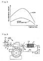
- Fig. 1 is a schematic front view of an internal combustion engine 100 into which the invention of claim 1 is embodied.
- the internal combustion engine 100 has an exhaust gas pipe 1 with which an NOx absorbing reduction catalyst 2 (hereinafter, referred to as an absorbing catalyst 2) is unitized.
- an oxygen sensor 3 In the exhaust gas passage (exhaust gas pipe 1) downstream of the absorbing catalyst 2, there is provided an oxygen sensor 3.
- an oxygen sensor 3a In the exhaust gas passage (exhaust gas pipe 1) upstream of the absorbing catalyst 2, there is provided an oxygen sensor 3a for precisely detecting the air-fuel ratio ⁇ of the exhaust gas.
- Each of the oxygen sensors 3, 3a is connected to a CPU 4 through signal cables 6, 6a, respectively. Signals detected by the oxygen sensors 3, 3a, are transmitted to the CPU 4 through the signal cables 6, 6a.
- the CPU 4 is accessible to a memory 5 which will be explained in detail below.
- Fig. 2 is a graph showing a waveform of a voltage outputted from the oxygen sensor 3.
- the absorbing catalyst 2 shown in Fig. 1 absorbs NOx included in the exhaust gas flowing through the exhaust gas pipe 1. But the absorbing catalyst 2 can absorb no more NOx once the amount of absorption thereof reaches a possible absorbing capacity.
- an operation called rich spike is executed in order to set the air-fuel ratio ⁇ slightly on a side of richness with respect to a theoretical air-fuel ratio.
- the rich spike is performed from time t 1 to time t 2 .
- the value of the air-fuel ratio ⁇ is greater (namely, leaner)
- the density of oxygen is higher.
- the voltage outputted from the oxygen sensor 3 decreases. Therefore, as shown in Fig. 2 , since the oxygen density is low during the rich spike, the voltage outputted therefrom is high.
- the value of the voltage hardly changes with respect to the value of E A during a time from t 3 to t 4 ("small amount of variation in voltage value" in claim 1), and the value thereof rapidly increases again after passing the time t 4 .
- the air-fuel ratio ⁇ is lean
- the absorbing catalyst 2 absorbs NO X and oxygen, simultaneously.
- the oxygen absorbed by the absorbing catalyst 2 is released, and the oxygen density in the exhaust gas pipe 1 downstream of the absorbing catalyst 2 becomes high temporarily.
- the oxygen density hardly changes during the time from t 3 to t 4 , which is reflected upon the value of voltage outputted from the oxygen sensor 3.
- the rich spike is performed five seconds, for example.
- the oxygen absorbed thereby at the time t 4 is released completely.
- the oxygen absorbed thereby at the time t 5 before reaching the time t 4 is released completely, for example, as shown in Fig. 2 .
- the absorbing catalyst 2 When the absorbing catalyst 2 is new and it has a high ability to absorb it, the absorbing catalyst 2 absorbs a lot of NO X together with oxygen. However, when the absorbing catalyst 2 is employed during many hours, and when the deterioration (poisoning by the sulfuric component) of the absorbing catalyst 2 proceeds, the ability to absorb it decreases. As a result, the amount of oxygen released at the time of executing the rich spike becomes small. Therefore, when the absorbing catalyst 2 is deteriorated, all the oxygen at the time t 5 shown in Fig. 2 is released completely, and the value of the voltage increases up to the highest value E B at a relatively early stage.
- the internal combustion engine 102 has an engine speed detector 13 and an engine load detector 14.
- the detection signals having been detected thereby, are supplied to the CPU 4.
- the exhaust gas pipe 1 has a temperature sensor 15.
- the CPU 4 estimates the temperature of the absorbing catalyst 2 from the temperature, detected by the temperature sensor 15, of exhaust gas.
- Fig. 5 shows a graph indicating a relation between the temperature of the absorbing catalyst 2 and the NO X possible absorbing capacity.
- the possible NO X absorbing capacity varies when the temperature becomes high, no matter whether the absorbing catalyst 2 is new or deteriorated. Therefore, it is possible to calculate the possible absorbing capacity thereof, from the degree of deterioration and temperature of the absorbing catalyst 2.
- the relation between the temperature and the possible absorbing capacity per degree of deterioration of the absorbing catalyst 2 is gained by experiment in advance, and then the map is made and stored on the memory 5.
- the temperature of the absorbing catalyst 2 changes in accordance with a state of operation of the internal combustion engine 102.
- the temperature thereof is detected by the temperature sensor 15, and the detection signal(s) detected thereby is/are transmitted to the CPU 4.
- Fig. 9 it is understood that the temperature of the exhaust gas (temperature of the absorbing catalyst 2) increases in each of the case that the engine load increases and the case that the engine speed increases.
- the degree of deterioration of the absorbing catalyst 2 can be estimated from the waveform of the voltage outputted by the oxygen sensor 3 shown in Fig. 2 . Consequently, the possible NO X absorbing amount at present by the absorbing catalyst 2 can be gained on the basis thereof.
- the amount per unit time of NO X which flows in the absorbing catalyst 2 is calculated by the CPU 4 (NO X amount calculation means).
- the CPU 4 performs the rich spike, when the amount thereof reaches 90-95%, for example, of the present possible absorbing capacity, calculated above, of the absorbing catalyst 2; and the NO X having been absorbed is reduced and removed. In this way, it is possible to bring out a full ability of the absorption in accordance with the deterioration of the absorbing catalyst 2, and possible to clean up the exhaust gas in good condition.
- an air supply pipe 7 and a fuel supply pipe 9 are connected to a mixer 8.
- a mixture formed in the mixer 8 is supplied from the mixer 8 to a combustion chamber (not shown) of the internal combustion engine 100 via a mixture supply pipe 11, and the mixture is made to combust in the combustion chamber.
- Fig. 13 shows a graph indicating a relation amongst the air-fuel ratio ⁇ , CO density and NO X density.
- the air-fuel ratio ⁇ is richer, the density of CO downstream of the absorbing catalyst is higher and the density of NO X is lower.
- the air-fuel ratio ⁇ is leaner, the density of CO downstream of the absorbing catalyst is lower and the density of NO X is higher.
- the region in which both of the CO density and the NO X density are relatively low, is called a cleanup window.
- the work for removing the sulfuric component from a deteriorated absorbing catalyst 2 is called a "recovery".
- the sulfuric component is removed from the absorbing catalyst 2, and the possible NO X absorbing capacity of the absorbing catalyst 2 is closer to the possible NO X absorbing capacity thereof when it is new.
- the internal combustion engine 100 is operated with such a temperature of the exhaust gas as allows the recovery. It is preferable that the temperature at this time is more than 600°C.
- the CO density downstream of the absorbing catalyst is set to be within an environmental discharge limit, and the CO density upstream of the absorbing catalyst is set so that the CO density downstream of the absorbing catalyst during the recovery of the absorbing catalyst become the set value.
- Fig. 14 shows a graph indicating a relation between a CO density set upstream of the absorbing catalyst and a time when the recovery is accomplished, in a case that the absorbing catalyst undergoes not so much deterioration and in a case that the absorbing catalyst undergoes considerable deterioration.
- the setting CO density is the same, the amount of poisoning increases as the deterioration thereof proceeds. Therefore, it takes longer before the recovery is finished. Also, making the recovery time the same, it is possible to set the CO density low at the time of recovery in a case that it undergoes less deterioration.
- the air-fuel ratio ⁇ upstream of the absorbing catalyst 2 is set so that the density of CO in the exhaust gas pipe 1 downstream of the absorbing catalyst 2 remains constant while the absorbing catalyst 2 is being recovered.
- the deterioration of the absorbing catalyst 2 is patterned on the basis of the degree of deterioration, a map is made by investigating a relation between the density of CO set downstream and the density of CO adjusted upstream, in advance, and the map is stored on the memory 5.
- the CPU 4 adjusts the valve travel of the fuel supply amount adjustment valve 10 so as to be able to properly adjust the density of CO upstream with reference to the map thus stored on the memory 5, by estimating the degree of the deterioration of the absorbing catalyst 2 from the waveform ( Fig. 2 ) of the voltage outputted from the oxygen sensor 3, and by selecting a setting value of the density of CO downstream.
- about 90-95% of the possible absorbing capacity of the absorbing catalyst 2 is set as the upper limit.
- the rich spike is performed during the time which is necessary for reducing and removing the NO X the amount of which corresponds to the estimated amount of NO X computed by the CPU 4.
- the rich spike is performed after the lean operation time during which the amount of NO X (or about 90-95% of the possible absorbing capacity), corresponding to the possible absorbing capacity of the absorbing catalyst 2, is absorbed, elapses.
- Fig. 11 is a schematic front view of the internal combustion engine 104 which is embodied in accordance with the invention of claim 5.
- the air-fuel ratio ⁇ at the time of recovering the absorbing catalyst 2 is set so that the density of CO in the exhaust gas pipe 1 upstream of the absorbing catalyst 2 is higher.
- the internal combustion engine 104 has an arrangement in which an oxidation catalyst 20 is provided in the exhaust gas passage (exhaust gas pipe 1) downstream of the absorbing catalyst 2.
- the internal combustion engine 104 has a pump 21, for supplying the secondary air, which is mounted in the exhaust passage upstream of the oxidation catalyst 20.
- a pump 21 for supplying the secondary air, which is mounted in the exhaust passage upstream of the oxidation catalyst 20.
- the oxygen sensor 3b is necessarily mounted upstream of the pump 21 in order not to allow the oxygen sensor 3b to detect oxygen in the secondary air.
- the oxygen sensor 3b detects only the oxygen passing through the absorbing catalyst 2, and the oxygen sensor 3b fulfills a role for monitoring the absorbing capacity of the absorbing catalyst 2.
- Other constructions of the internal combustion engine 104 are the same as those of the internal combustion engine 100. Air supplied by the pump 21 oxidizes (i.e. cleans up) CO in the oxidation catalyst 20.
- the cleanup by the oxidation catalyst 20 can be done even if a bit excessive amount of CO is supplied, and it is easy to control the air-fuel ratio. Namely, in the internal combustion engine 104, the oxygen sensor 3a can be skipped.
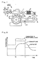
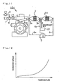
- Fig. 6 is a schematic front view of the internal combustion engine 103 which is embodied in accordance with the invention of claims 6 and 7.
- the internal combustion engine 103 differs from the internal combustion engine 100, only in that a three way catalyst 19 is arranged upstream of the absorbing catalyst 2.
- the other constructions of the internal combustion engine 103 are the same as those of the internal combustion engine 100.
- the fuel supply amount adjustment valve 10 is operated until the value of voltage outputted from the oxygen sensor 3a rapidly changes, and the air-ratio ⁇ prior to the operation of the fuel supply amount adjustment valve 10 is detected on the basis of the operation amount of the fuel supply amount adjustment valve 10. This operation is called a lean spike.
- the lean spike is executed. After detecting what value the present air-fuel ratio ⁇ is, the air-fuel ratio ⁇ is shifted toward a rich side by an amount necessary to recover it.
- the recovery of the absorbing catalyst 2 is blocked. Therefore, it is necessary to remove oxygen generated at the time of execution of the lean spike, before the recovery work is started. Namely, the oxygen is absorbed by the three way catalyst 19 mounted upstream of the absorbing catalyst 2, and the oxygen is prevented from flowing to the absorbing catalyst 2 downstream.
- Fig. 12 is a graph showing a relation between the recovery speed and temperature of the absorbing catalyst 2. As shown in Fig. 12 , the recovery speed of the absorbing catalyst 2 is higher as the temperature is higher. Therefore, in the internal combustion engine 103, the absorbing catalyst 2 can be recovered in a short time by the exhaust gas at a high temperature.
- the present invention is applicable to internal combustion land and marine engines which are equipped with NO x absorbing reduction catalysts in the exhaust gas passages.
Landscapes
- Engineering & Computer Science (AREA)
- Chemical & Material Sciences (AREA)
- Combustion & Propulsion (AREA)
- Mechanical Engineering (AREA)
- General Engineering & Computer Science (AREA)
- Chemical Kinetics & Catalysis (AREA)
- Environmental & Geological Engineering (AREA)
- Biomedical Technology (AREA)
- Health & Medical Sciences (AREA)
- Analytical Chemistry (AREA)
- General Chemical & Material Sciences (AREA)
- Oil, Petroleum & Natural Gas (AREA)
- Exhaust Gas After Treatment (AREA)
- Cylinder Crankcases Of Internal Combustion Engines (AREA)
- Filtering Of Dispersed Particles In Gases (AREA)
- Electrical Control Of Air Or Fuel Supplied To Internal-Combustion Engine (AREA)
- Combined Controls Of Internal Combustion Engines (AREA)
- Exhaust Gas Treatment By Means Of Catalyst (AREA)
Abstract
Description
- The present invention relates to an exhaust gas cleanup device for an internal combustion engine provided with a NOx absorbing reduction catalyst which locates in an exhaust gas passage.
- In an internal combustion engine provided with a NOx absorbing reduction catalyst (hereinafter, referred to as absorbing catalyst) which locates in an exhaust gas passage, when NOx is absorbed by the absorbing catalyst up to a certain level, the NOx thus absorbed is reduced and removed by executing an operation called a rich spike by which an air-fuel ratio is switched temporarily and rapidly from leanness to richness.
- As an invention of method for recovering the absorbing catalyst by the rich spike, there is a Japanese Laid-Open Patent Publication No.
2000-45752 2000-45752 - The absorbing catalyst is, however, poisoned by a sulfuric component included in the exhaust gas, and the absorbing catalyst deteriorates with time passing so that the possible absorbing capacity of NOx decreases. As a method for removing the sulfuric component from the poisoned absorbing catalyst, there is a Japanese Laid-Open Patent Publication No.
2000-8909 2000-8909 - In this way, according to the conventional art, to which degree the absorbing catalyst is poisoned by the sulfuric component is estimated only from the operation time of the internal combustion engine. That is, the recovering work is performed mechanically when the predetermined time passes, without monitoring the actual deteriorating condition of the absorbing catalyst. The "deterioration of the absorbing catalyst" means decrease of performance of cleanup of the absorbing catalyst on the basis of the poisoning by the sulfuric component and by heat.
- The technical object is directed toward a provision of an exhaust gas cleanup device for an internal combustion engine, in which a condition of actual deterioration of the absorbing catalyst is monitored, and in which it is possible to recover the absorbing catalyst in a short time.
- According to the invention of
claim 1, in order to achieve the aforementioned technical object, in an exhaust gas cleanup device of an internal combustion engine which is provided with an NOX absorbing reduction catalyst in an exhaust gas passage, there is provided a method characterized by the steps of: - determining a condition of deterioration of the NOX absorbing reduction catalyst (2) on the basis of a time length taken by a voltage value, outputted from an oxygen sensor (3) which is mounted downstream of the NOX absorbing reduction catalyst (2) in the exhaust gas passage (1), to remain at a level equal to or having a small amount of variation from a value (EA), during the execution of a rich spike;
- calculating the amount of NOX flowing in the NOX absorbing reduction catalyst (2) per unit time from an exhaust gas flow rate detected by an exhaust gas flow rate detecting means and from a concentration of NOX in the exhaust gas detected by an NOX concentration detecting means;
- estimating a possible NOX absorbing capacity of the NOX absorbing reduction catalyst (2) based on a temperature of the NOX absorbing reduction catalyst (2) detected by a temperature sensor (15) and on the time length taken by the voltage value to remain at a level equal to or having a small amount of variation from the value (EA) detected by the oxygen sensor (3),
- According to the invention of
claim 2, there is provided the method ofclaim 1, further comprising the step of setting the concentration of CO, using an air-fuel ratio setting means, so as to increase the concentration of CO inside the exhaust gas passage which is upstream of the NOX absorbing reduction catalyst at a time of recovering the NOX absorbing reduction catalyst, as the degree of the deterioration, determined by the determination means, of the NOX absorbing reduction catalyst becomes higher. - According to the invention of
claim 3, there is provided the method ofclaim 2, wherein an air-fuel ratio in the exhaust gas passage which is upstream of the NOX absorbing reduction catalyst is set so that the concentration of CO upstream is high initially at the time of recovery and wherein the concentration of CO in the exhaust gas passage which is downstream of the NOX absorbing reduction catalyst is kept constant at the time of recovering the NOX absorbing reduction catalyst. - According to the invention of
claim 4, there is provided the method ofclaim 1, wherein the estimated possible NOX absorbing capacity of the NOX absorbing reduction catalyst which is deteriorated, is estimated, and
wherein an interval for executing the rich spike is set in compliance with the possible NOX absorbing capacity. - According to the invention of
claim 5, there is provided the method ofclaim 2 orclaim 3, wherein a secondary air supply passage and an oxidation catalyst are provided in the exhaust gas passage downstream of the NOX absorbing reduction catalyst, and wherein CO having passed through the NOX absorbing reduction catalyst (2) is oxidized in the oxidation catalyst. - According to the invention of
claim 6, there is provided the method ofclaim 1, wherein a three way catalyst is provided in the exhaust gas passage upstream of the NOX absorbing reduction catalyst, and wherein the three way catalyst has an oxygen absorbing function and an oxidizing function. - According to the invention of claim 7, there is provided the method of
claim 6, wherein the three way catalyst and the NOX absorbing reduction catalyst are unitized integrally, and wherein the three way catalyst is upstream of the exhaust gas passage. - According to the invention of
claim 1, theCPU 4 compares the voltage data outputted from theoxygen sensor 3 in which the voltage data are about the absorbingreduction catalyst 2 that is not deteriorated and in which the voltage data are stored on thememory 5, and the waveform of the value, actually measured, of voltage outputted from theoxygen sensor 3 at the time of executing the rich spike, to each other. On the basis of the comparison, the degree of course of deterioration of the absorbingreduction catalyst 2 can be estimated. Therefore, it is possible to keep the absorbingreduction catalyst 2 in a condition for exerting the NOX absorbing function fully, and the NOX can be purged in good condition. - Also, the possible NOX absorbing capacity of the absorbing
catalyst 2 is estimated, and the absorbingcatalyst 2 is recovered when the total amount of NOX (accumulated amount of NOX) flowing in the absorbingcatalyst 2 reaches the possible NOX absorbing capacity. Therefore, it is possible to exert the absorbing ability of the absorbingcatalyst 2 to the fullest extent. - Regardless of change in operational circumstances such as engine speed, engine load, etc., the total amount of the discharged NOX is calculated. Therefore, it is possible to properly determine the time to recover the absorbing
catalyst 2, and the good absorbing ability can be exerted. - According to the invention of
claim 2, there is provided the air-fuel ratio setting means (fuel supply amount adjustment valve) for setting the density of CO inside the exhaust gas passage (exhaust gas pipe 1) which is upstream of the NOX absorbing catalyst 2, in compliance with the degree of deterioration of the absorbingcatalyst 2; therefore, the NOX absorbing catalyst 2 can be recovered in good condition. Consequently, always, the NOX can be purged in good condition. - According to the invention of
claim 3, in the invention ofclaim 2, the air-fuel ratio λ which is upstream of the NOX absorbingreduction catalyst 2 is set so that the density of CO which is downstream of the NOX absorbingreduction catalyst 2 is kept constant. Therefore, it is possible to make the time for recovering theabsorbing catalyst 2 the shortest while the density of discharged CO is suppressed to a predetermined density within a value of an environmental limit. Consequently, it is possible to maintain the thermal efficiency high. - According to the invention of
claim 4, the possible NOX absorbing capacity is estimated in compliance with the degree of deterioration of the absorbingcatalyst 2, and the interval for performing the rich spike is set up. Therefore, the minimum necessary recovery can be performed in compliance with the degree of deterioration of the absorbingcatalyst 2, the operation time can be the shortest with the air-fuel ratio λ being rich, the discharge of CO can be made minimum, and the heat efficiency can be maintained high. - According to the invention of
claim 5, there is arranged theoxidation catalyst 20 which is in the exhaust gas passage (exhaust gas pipe 1) downstream of the absorbingcatalyst 2. Therefore, the discharge of CO which has not been employed upon recovery of the absorbingreduction catalyst 2, into the atmospheric air, is surely prevented. In other words, even if a large amount of CO, effective in the recovery, is flowed, the CO (CO which has not been employed for recovery) having passed through the absorbingcatalyst 2 can undergo an oxidizing process by theoxidation catalyst 20. Therefore, the discharge of CO into the air can be prevented. - According to the invention of
claim 6, there is arranged the three way catalyst 19 which is in the exhaust gas passage (exhaust gas pipe 1) upstream of the absorbingcatalyst 2, and oxygen is absorbed upstream of the absorbingcatalyst 2 by the three way catalyst 19 at the time of recovery of the absorbingcatalyst 2. Therefore, the absorbingcatalyst 2 can be recovered in good condition, and the good cleaning ability can be realized. - According to the invention of claim 7, the three way catalyst 19 and the absorbing
catalyst 2 are unitized integrally, which are provided in the exhaust gas passage (exhaust gas pipe 1). Therefore, the temperature of the exhaust gas between the three way catalyst 19 and the absorbingcatalyst 2, can be prevented from dropping down, and it is possible to recover the absorbingcatalyst 2 at a high temperature. Therefore, the absorbingcatalyst 2 can be surely recovered, and the absorbingcatalyst 2 can make the NOX be cleaned up in good condition. -
-
Fig. 1 is a schematic front view of an internal combustion engine which is embodied according to the invention ofclaim 1. -
Fig. 2 is a graph showing a waveform of a voltage outputted from an oxygen sensor. -
Fig. 3 is a graph showing a change in CO density upstream and downstream of an absorbing catalyst when time elapses. -
Fig. 4 is a graph showing a change in CO density upstream of the absorbing catalyst, with the CO density downstream of the absorbing catalyst being kept constant. -
Fig. 5 is a graph showing a relation between temperature of the absorbing catalyst and possible NOx absorbing capacity. -
Fig. 6 is a schematic front view of the internal combustion engine which is embodied according to the invention ofclaims 7 and 8. -
Fig. 7 is a schematic front view of the internal combustion engine which is embodied according to the invention ofclaim 4. -
Fig. 8 is a graph showing a change in temperature of exhaust gas with time passing, when a condition of operation of the internal combustion engine ofFig. 7 changes. -
Fig. 9 is a graph showing a temperature distribution of the absorbing catalyst on the basis of the engine load and engine speed. -
Fig. 10 is a graph showing a relation between recovering speed of the absorbing catalyst and air-fuel ratio λ. -
Fig. 11 is a schematic front view of the internal combustion engine which is embodied according to the invention ofclaim 6. -
Fig. 12 is a graph showing a relation between the recovering speed of the absorbing catalyst and the temperature. -
Fig. 13 is a graph showing a relation between the air-fuel ratio λ, and CO and NOx densities downstream of the absorbing catalyst. -
Fig. 14 is a graph showing a relation between a CO density set upstream of the absorbing catalyst and time when the recovery thereof has been accomplished, in a case that the absorbing catalyst is not deteriorated so much and in a case that the absorbing catalyst is deteriorated appreciably. -
Fig. 1 is a schematic front view of aninternal combustion engine 100 into which the invention ofclaim 1 is embodied. Theinternal combustion engine 100 has anexhaust gas pipe 1 with which an NOx absorbing reduction catalyst 2 (hereinafter, referred to as an absorbing catalyst 2) is unitized. In the exhaust gas passage (exhaust gas pipe 1) downstream of the absorbingcatalyst 2, there is provided anoxygen sensor 3. Also, in the exhaust gas passage (exhaust gas pipe 1) upstream of the absorbingcatalyst 2, there is provided anoxygen sensor 3a for precisely detecting the air-fuel ratio λ of the exhaust gas. Each of theoxygen sensors CPU 4 throughsignal cables oxygen sensors CPU 4 through thesignal cables CPU 4 is accessible to amemory 5 which will be explained in detail below. -
Fig. 2 is a graph showing a waveform of a voltage outputted from theoxygen sensor 3. The absorbingcatalyst 2 shown inFig. 1 , absorbs NOx included in the exhaust gas flowing through theexhaust gas pipe 1. But theabsorbing catalyst 2 can absorb no more NOx once the amount of absorption thereof reaches a possible absorbing capacity. When the amount of absorption reaches 90%, for example, of the possible absorbing capacity, an operation called rich spike is executed in order to set the air-fuel ratio λ slightly on a side of richness with respect to a theoretical air-fuel ratio. - Referring to
Fig. 2 , the rich spike is performed from time t1 to time t2. When the internal combustion engine 100 (Fig. 1 ) operates normally, the air-fuel ratio λ is set to be lean (λ=1.3 ∼1.5). As the value of the air-fuel ratio λ is greater (namely, leaner), the density of oxygen is higher. As the oxygen density is higher, the voltage outputted from theoxygen sensor 3 decreases. Therefore, as shown inFig. 2 , since the oxygen density is low during the rich spike, the voltage outputted therefrom is high. - In
Fig. 2 , the value of the voltage hardly changes with respect to the value of EA during a time from t3 to t4 ("small amount of variation in voltage value" in claim 1), and the value thereof rapidly increases again after passing the time t4. When the air-fuel ratio λ is lean, the absorbingcatalyst 2 absorbs NOX and oxygen, simultaneously. When the rich spike is executed, the oxygen absorbed by the absorbingcatalyst 2 is released, and the oxygen density in theexhaust gas pipe 1 downstream of the absorbingcatalyst 2 becomes high temporarily. And, in spite of executing the rich spike until all the oxygen thus absorbed is released completely, the oxygen density hardly changes during the time from t3 to t4, which is reflected upon the value of voltage outputted from theoxygen sensor 3. - The rich spike is performed five seconds, for example. When the absorbing
catalyst 2 is new, the oxygen absorbed thereby at the time t4 is released completely. When the deterioration of the absorbingcatalyst 2 proceeds, the oxygen absorbed thereby at the time t5 before reaching the time t4, is released completely, for example, as shown inFig. 2 . - When the absorbing
catalyst 2 is new and it has a high ability to absorb it, the absorbingcatalyst 2 absorbs a lot of NOX together with oxygen. However, when the absorbingcatalyst 2 is employed during many hours, and when the deterioration (poisoning by the sulfuric component) of the absorbingcatalyst 2 proceeds, the ability to absorb it decreases. As a result, the amount of oxygen released at the time of executing the rich spike becomes small. Therefore, when the absorbingcatalyst 2 is deteriorated, all the oxygen at the time t5 shown inFig. 2 is released completely, and the value of the voltage increases up to the highest value EB at a relatively early stage. - Consequently, it is possible to know the degree of course of deterioration of the absorbing
catalyst 2, on the basis of the waveform of the voltage outputted from theoxygen sensor 3. Accordingly, the correlation between the oxygen absorbing amount (NOX absorbing amount) of the NOX absorbing catalyst 2 and the waveform of the voltage, is gained by experiment in advance, and the correlation therebetween is stored on thememory 5 inFig. 1 . By comparing data stored on thememory 5 and the waveform of the value of voltage, actually measured, which is outputted from theoxygen sensor 3 at the time of executing the rich spike with theCPU 4, it is possible to estimate the degree of course of deterioration of the absorbingcatalyst 2. - As shown in
Fig. 7 , theinternal combustion engine 102 has anengine speed detector 13 and anengine load detector 14. The detection signals having been detected thereby, are supplied to theCPU 4. Also, theexhaust gas pipe 1 has atemperature sensor 15. TheCPU 4 estimates the temperature of the absorbingcatalyst 2 from the temperature, detected by thetemperature sensor 15, of exhaust gas. -
Fig. 5 shows a graph indicating a relation between the temperature of the absorbingcatalyst 2 and the NOX possible absorbing capacity. As shown inFig. 5 , the possible NOX absorbing capacity varies when the temperature becomes high, no matter whether the absorbingcatalyst 2 is new or deteriorated. Therefore, it is possible to calculate the possible absorbing capacity thereof, from the degree of deterioration and temperature of the absorbingcatalyst 2. - Firstly, the relation between the temperature and the possible absorbing capacity per degree of deterioration of the absorbing
catalyst 2, is gained by experiment in advance, and then the map is made and stored on thememory 5. The temperature of the absorbingcatalyst 2 changes in accordance with a state of operation of theinternal combustion engine 102. The temperature thereof is detected by thetemperature sensor 15, and the detection signal(s) detected thereby is/are transmitted to theCPU 4. Incidentally, as shown inFig. 9 , it is understood that the temperature of the exhaust gas (temperature of the absorbing catalyst 2) increases in each of the case that the engine load increases and the case that the engine speed increases. - The degree of deterioration of the absorbing
catalyst 2 can be estimated from the waveform of the voltage outputted by theoxygen sensor 3 shown inFig. 2 . Consequently, the possible NOX absorbing amount at present by the absorbingcatalyst 2 can be gained on the basis thereof. - Next, how much density the NOX which flows in the absorbing
catalyst 2 has, is checked. It is possible to estimate the condition of operation of theinternal combustion engine 100 from the air-fuel ratio λ, the engine speed detected by theengine speed detector 13, and the engine load detected by theengine load detector 14. On the basis of these, it is possible to detect the exhaust gas flow rate and the density of NOX included in the exhaust gas (exhaust gas flow rate detection means and NOX density detection means). - The amount per unit time of NOX which flows in the absorbing
catalyst 2, is calculated by the CPU 4 (NOX amount calculation means). TheCPU 4 performs the rich spike, when the amount thereof reaches 90-95%, for example, of the present possible absorbing capacity, calculated above, of the absorbingcatalyst 2; and the NOX having been absorbed is reduced and removed. In this way, it is possible to bring out a full ability of the absorption in accordance with the deterioration of the absorbingcatalyst 2, and possible to clean up the exhaust gas in good condition. - Of course, it is possible to absorb it until the total amount (accumulated NOX amount) of NOX calculated by the
CPU 4reaches 100% of the possible absorbing capacity of the absorbingcatalyst 2, and it is possible to perform the rich spike thereafter. However, there is a possibility that the amount of NOX in the exhaust gas discharged to the atmospheric air increases. Therefore, it is preferable to set about 90-95% of the possible absorbing capacity as an upper limit, as aforementioned. - As shown in
Fig. 1 , an air supply pipe 7 and a fuel supply pipe 9 are connected to amixer 8. A mixture formed in themixer 8, is supplied from themixer 8 to a combustion chamber (not shown) of theinternal combustion engine 100 via a mixture supply pipe 11, and the mixture is made to combust in the combustion chamber. - The air-fuel ratio λ of the mixture supplied to the combustion chamber, can be changed by adjusting the valve travel of a fuel supply
amount adjustment valve 10 which is provided intermediately in the fuel supply pipe 9. Namely, when the degree of the valve travel is made small, the amount of supply of the fuel decreases, and therefore the air-fuel ratio λ becomes high (i.e. becomes lean). On the contrary, when the degree of the valve travel is made large, the air-fuel ratio λ becomes low (i.e. becomes rich). The change of the air-fuel λ, in the vicinity of λ =1, is detected by theoxygen sensor 3a with high precision. -
Fig. 13 shows a graph indicating a relation amongst the air-fuel ratio λ, CO density and NOX density. As shown inFig. 13 , as the air-fuel ratio λ is richer, the density of CO downstream of the absorbing catalyst is higher and the density of NOX is lower. On the contrary, as the air-fuel ratio λ is leaner, the density of CO downstream of the absorbing catalyst is lower and the density of NOX is higher. The region in which both of the CO density and the NOX density are relatively low, is called a cleanup window. - The work for removing the sulfuric component from a deteriorated absorbing
catalyst 2, is called a "recovery". When the absorbingcatalyst 2 is recovered, the sulfuric component is removed from the absorbingcatalyst 2, and the possible NOX absorbing capacity of the absorbingcatalyst 2 is closer to the possible NOX absorbing capacity thereof when it is new. - As shown in
Fig. 10 , as the CO density is higher, the recovery speed is faster. The sulfuric component is advantageously removed with higher CO density. Hence, at the time of recovery thereof, the valve travel of the fuel supply amount adjustment valve (air-fuel ratio setting means) 10 is adjusted, and the air-fuel ratio λ is set to be on an end ( λ=0.99-0.997) of the rich side of the cleanup window. At the same time, theinternal combustion engine 100 is operated with such a temperature of the exhaust gas as allows the recovery. It is preferable that the temperature at this time is more than 600°C. - As shown in
Fig. 3 , when the CO density upstream of the catalyst is kept constant, the CO density downstream of the absorbing catalyst becomes low initially. But when the time tA comes, the CO density downstream of the absorbing catalyst increases up to a predetermined value. When a new absorbing catalyst having a large possible absorbing capacity absorbs the NOX and oxygen up to a limitation of absorption, the amount of oxygen and NOX which is made to react with CO at the time of reduction of the absorbing catalyst increases. Therefore, there does not exist any object (NOX and oxygen) with which CO reacts, and it takes long before the CO density increases up to a predetermined value. But the possible absorbing capacity of the absorbing catalyst undergoing a considerable poisoning is small, and the amount of oxygen and NOX having been absorbed is small. Therefore, the amount of oxygen and NOX which is made to react with CO at the time of reduction of the absorbing catalyst is small, and the CO density increases up to the predetermined value when the time tA, prior to the time tB, comes. - As shown in
Fig. 4 , when the CO density is set to be high initially at the time of recovery thereof, not so much of CO flows downstream of the absorbing catalyst. Accordingly, by setting the CO density upstream of the absorbing catalyst to be low in accordance with the degree of the recovery, it is possible to shorten the time to recover the absorbing catalyst while suppressing the CO density downstream of the absorbing catalyst. - In
Fig. 4 , the CO density downstream of the absorbing catalyst is set to be within an environmental discharge limit, and the CO density upstream of the absorbing catalyst is set so that the CO density downstream of the absorbing catalyst during the recovery of the absorbing catalyst become the set value. By heightening the CO density upstream of the absorbing catalyst in advance during the recovery so that the CO density downstream of the absorbing catalyst does not exceed the environmental limit, it is possible to shorten the time of the recovery of the absorbing catalyst with the density of CO in the exhaust gas being kept low. -
Fig. 14 shows a graph indicating a relation between a CO density set upstream of the absorbing catalyst and a time when the recovery is accomplished, in a case that the absorbing catalyst undergoes not so much deterioration and in a case that the absorbing catalyst undergoes considerable deterioration. As shown inFig. 14 , when the setting CO density is the same, the amount of poisoning increases as the deterioration thereof proceeds. Therefore, it takes longer before the recovery is finished. Also, making the recovery time the same, it is possible to set the CO density low at the time of recovery in a case that it undergoes less deterioration. - In the embodiment of the invention of
claim 2, the air-fuel ratio λ upstream of the absorbingcatalyst 2 is set so that the density of CO in theexhaust gas pipe 1 downstream of the absorbingcatalyst 2 remains constant while the absorbingcatalyst 2 is being recovered. - The deterioration of the absorbing
catalyst 2 is patterned on the basis of the degree of deterioration, a map is made by investigating a relation between the density of CO set downstream and the density of CO adjusted upstream, in advance, and the map is stored on thememory 5. - The
CPU 4 adjusts the valve travel of the fuel supplyamount adjustment valve 10 so as to be able to properly adjust the density of CO upstream with reference to the map thus stored on thememory 5, by estimating the degree of the deterioration of the absorbingcatalyst 2 from the waveform (Fig. 2 ) of the voltage outputted from theoxygen sensor 3, and by selecting a setting value of the density of CO downstream. - In the embodiment of
claim 1, about 90-95% of the possible absorbing capacity of the absorbingcatalyst 2 is set as the upper limit. At the time of reducing and removing the NOX having been absorbed, the rich spike is performed during the time which is necessary for reducing and removing the NOX the amount of which corresponds to the estimated amount of NOX computed by theCPU 4. - That is, the rich spike is performed after the lean operation time during which the amount of NOX (or about 90-95% of the possible absorbing capacity), corresponding to the possible absorbing capacity of the absorbing
catalyst 2, is absorbed, elapses. - When the rich spike is executed in this way, it is possible to cleanup the absorbing catalyst in good condition, to suppress to a requisite minimum the amount of CO discharged when the air-fuel ratio λ is rich, and to suppress the decrease of the thermal efficiency to a minimum.
-
Fig. 11 is a schematic front view of theinternal combustion engine 104 which is embodied in accordance with the invention ofclaim 5. According to the invention of theaforementioned claims catalyst 2, is set so that the density of CO in theexhaust gas pipe 1 upstream of the absorbingcatalyst 2 is higher. But it is necessary to take a counter measure for preventing CO, which does not contribute to the cleanup of the NOX and SOX in the exhaust gas, from being discharged into the atmospheric air. Consequently, theinternal combustion engine 104 has an arrangement in which anoxidation catalyst 20 is provided in the exhaust gas passage (exhaust gas pipe 1) downstream of the absorbingcatalyst 2. - Further, the
internal combustion engine 104 has apump 21, for supplying the secondary air, which is mounted in the exhaust passage upstream of theoxidation catalyst 20. There is installed anoxygen sensor 3b between thepump 21 and the absorbingcatalyst 2. Theoxygen sensor 3b is necessarily mounted upstream of thepump 21 in order not to allow theoxygen sensor 3b to detect oxygen in the secondary air. Theoxygen sensor 3b detects only the oxygen passing through the absorbingcatalyst 2, and theoxygen sensor 3b fulfills a role for monitoring the absorbing capacity of the absorbingcatalyst 2. Other constructions of theinternal combustion engine 104 are the same as those of theinternal combustion engine 100. Air supplied by thepump 21 oxidizes (i.e. cleans up) CO in theoxidation catalyst 20. - Incidentally, in the invention of
claims - In this respect, according to the invention of
claim 6, the cleanup by theoxidation catalyst 20 can be done even if a bit excessive amount of CO is supplied, and it is easy to control the air-fuel ratio. Namely, in theinternal combustion engine 104, theoxygen sensor 3a can be skipped. -
Fig. 6 is a schematic front view of theinternal combustion engine 103 which is embodied in accordance with the invention ofclaims 6 and 7. Theinternal combustion engine 103 differs from theinternal combustion engine 100, only in that a three way catalyst 19 is arranged upstream of the absorbingcatalyst 2. However, the other constructions of theinternal combustion engine 103 are the same as those of theinternal combustion engine 100. Upon control of the air-fuel ratio λ, the fuel supplyamount adjustment valve 10 is operated until the value of voltage outputted from theoxygen sensor 3a rapidly changes, and the air-ratio λ prior to the operation of the fuel supplyamount adjustment valve 10 is detected on the basis of the operation amount of the fuel supplyamount adjustment valve 10. This operation is called a lean spike. Upon the recovery of the absorbingcatalyst 2, firstly, the lean spike is executed. After detecting what value the present air-fuel ratio λ is, the air-fuel ratio λ is shifted toward a rich side by an amount necessary to recover it. - When there exists oxygen, the recovery of the absorbing
catalyst 2 is blocked. Therefore, it is necessary to remove oxygen generated at the time of execution of the lean spike, before the recovery work is started. Namely, the oxygen is absorbed by the three way catalyst 19 mounted upstream of the absorbingcatalyst 2, and the oxygen is prevented from flowing to the absorbingcatalyst 2 downstream. - As shown in
Fig. 6 , by unitizing the three way catalyst 19 and the absorbingcatalyst 2, and by mounting the unit in the exhaust gas passage (exhaust gas pipe 1), the temperature of the exhaust gas between the three way catalyst 19 and the absorbingcatalyst 2 is prevented from dropping down. -
Fig. 12 is a graph showing a relation between the recovery speed and temperature of the absorbingcatalyst 2. As shown inFig. 12 , the recovery speed of the absorbingcatalyst 2 is higher as the temperature is higher. Therefore, in theinternal combustion engine 103, the absorbingcatalyst 2 can be recovered in a short time by the exhaust gas at a high temperature. - The present invention is applicable to internal combustion land and marine engines which are equipped with NOx absorbing reduction catalysts in the exhaust gas passages.
Claims (7)
- A method for determining when to perform a rich spike in an exhaust gas cleanup device of an internal combustion engine (100) which is provided with an NOX absorbing reduction catalyst (2) in an exhaust gas passage (1), the method characterized by the steps of:determining a condition of deterioration of the NOX absorbing reduction catalyst (2) on the basis of a time length taken by a voltage value, outputted from an oxygen sensor (3) which is mounted downstream of the NOX absorbing reduction catalyst (2) in the exhaust gas passage (1), to remain at a level equal to or having a small amount of variation from a value (EA), during the execution of a rich spike;calculating the amount of NOX flowing in the NOX absorbing reduction catalyst (2) per unit time from an exhaust gas flow rate detected by an exhaust gas flow rate detecting means and from a concentration of NOX in the exhaust gas detected by an NOX concentration detecting means;estimating a possible NOX absorbing capacity of the NOX absorbing reduction catalyst (2) based on a temperature of the NOX absorbing reduction catalyst (2) detected by a temperature sensor (15) and on the time length taken by the voltage value to remain at a level equal to or having a small amount of variation from the value (EA) detected by the oxygen sensor (3),wherein the NOX absorbing reduction catalyst (2) is recovered when an estimated amount of NOX flowing in the NOX absorbing reduction catalyst (2) reaches an estimated possible absorbing amount.
- The method of claim 1, further comprising the step of setting the concentration of CO, using an air-fuel ratio setting means, so as to increase the concentration of CO inside the exhaust gas passage (1) which is upstream of the NOX absorbing reduction catalyst (2) at a time of recovering the NOX absorbing reduction catalyst (2), as degree of the deterioration, determined by the determination means, of the NOX absorbing reduction catalyst (2) becomes higher.
- The method of claim 2, wherein an air-fuel ratio in the exhaust gas passage (1) which is upstream of the NOX absorbing reduction catalyst (2) is set so that the concentration of CO upstream is high initially at the time of recovery and the concentration of CO in the exhaust gas passage (1) which is downstream of the NOX absorbing reduction catalyst (2) is kept constant at the time of recovering the NOX absorbing reduction catalyst (2)
- The method of claim 1, wherein the estimated possible NOX absorbing capacity of the NOX absorbing reduction catalyst (2) which is deteriorated, is estimated, and
wherein an interval for executing the rich spike is set in compliance with the possible NOX absorbing capacity. - The method of claim 2 or claim 3, wherein a secondary air supply passage and an oxidation catalyst are both provided in the exhaust gas passage (1) downstream of the NOX absorbing reduction catalyst (2), and wherein CO having passed through the NOX absorbing reduction catalyst (2) is oxidized in the oxidation catalyst.
- The method of claim 1, wherein a three way catalyst (19) is provided in the exhaust gas passage (1) upstream of the NOX absorbing reduction catalyst (2), and wherein the three way catalyst (19) has an oxygen absorbing function and an oxidizing function.
- The method of claim 6, wherein the three way catalyst (19) and the NOX absorbing reduction catalyst (2) are unitized integrally, and wherein the three way catalyst (19) is upstream of the NO X absorbing reduction catalyst (2).
Applications Claiming Priority (3)
| Application Number | Priority Date | Filing Date | Title |
|---|---|---|---|
| JP2001115470A JP2002309928A (en) | 2001-04-13 | 2001-04-13 | Exhaust emission control device for internal combustion engine |
| JP2001115470 | 2001-04-13 | ||
| PCT/JP2002/003562 WO2002084086A1 (en) | 2001-04-13 | 2002-04-10 | Exhaust gas cleaner for internal combustion engine |
Publications (3)
| Publication Number | Publication Date |
|---|---|
| EP1384866A1 EP1384866A1 (en) | 2004-01-28 |
| EP1384866A4 EP1384866A4 (en) | 2005-10-05 |
| EP1384866B1 true EP1384866B1 (en) | 2009-12-09 |
Family
ID=18966364
Family Applications (1)
| Application Number | Title | Priority Date | Filing Date |
|---|---|---|---|
| EP02717090A Expired - Lifetime EP1384866B1 (en) | 2001-04-13 | 2002-04-10 | Exhaust gas cleaner for internal combustion engine |
Country Status (8)
| Country | Link |
|---|---|
| US (1) | US7010907B2 (en) |
| EP (1) | EP1384866B1 (en) |
| JP (1) | JP2002309928A (en) |
| KR (1) | KR100529708B1 (en) |
| CN (1) | CN1323228C (en) |
| AT (1) | ATE451545T1 (en) |
| DE (1) | DE60234685D1 (en) |
| WO (1) | WO2002084086A1 (en) |
Families Citing this family (23)
| Publication number | Priority date | Publication date | Assignee | Title |
|---|---|---|---|---|
| DE10300298A1 (en) | 2003-01-02 | 2004-07-15 | Daimlerchrysler Ag | Exhaust gas aftertreatment device and method |
| JP4304428B2 (en) * | 2003-02-07 | 2009-07-29 | いすゞ自動車株式会社 | Exhaust gas purification system for internal combustion engine |
| JP3873904B2 (en) * | 2003-02-26 | 2007-01-31 | 日産自動車株式会社 | Exhaust gas purification device for internal combustion engine |
| FR2856730A1 (en) * | 2003-06-24 | 2004-12-31 | Jean Claude Fayard | Catalyzer, for treating exhaust gases emitted controlled spark engine, has reduction and oxidation catalysts, and has controller that adjusts combustion to be very slightly rich |
| FR2866926B1 (en) * | 2004-02-27 | 2008-02-22 | Peugeot Citroen Automobiles Sa | DIAGNOSTIC METHOD FOR AN EXHAUST GAS CATALYST OF A THERMAL MOTOR AND VEHICLE USING THE SAME |
| JP3852461B2 (en) | 2004-09-03 | 2006-11-29 | いすゞ自動車株式会社 | Exhaust gas purification method and exhaust gas purification system |
| JP4665923B2 (en) * | 2007-03-13 | 2011-04-06 | トヨタ自動車株式会社 | Catalyst deterioration judgment device |
| JP4175427B1 (en) * | 2007-05-16 | 2008-11-05 | いすゞ自動車株式会社 | NOx purification system control method and NOx purification system |
| JP2010127091A (en) * | 2008-11-25 | 2010-06-10 | Toyota Motor Corp | Deterioration detecting method of exhaust emission control catalyst |
| WO2010108083A1 (en) * | 2009-03-20 | 2010-09-23 | Basf Catalysts Llc | EMISSIONS TREATMENT SYSTEM WITH LEAN NOx TRAP |
| AP2014007408A0 (en) * | 2011-08-16 | 2014-02-28 | Transocean Sedco Forex Ventures Ltd | Measurement of diesel engine emissions |
| KR101733329B1 (en) * | 2013-01-29 | 2017-05-08 | 도요타지도샤가부시키가이샤 | Control device for internal combustion engine |
| US9441566B2 (en) | 2013-03-29 | 2016-09-13 | Honda Motor Co., Ltd. | Exhaust emission purification control device for engine |
| US9664094B2 (en) * | 2013-09-26 | 2017-05-30 | General Electric Company | Systems and methods for monitoring catalyst deactivation and controlling an air/fuel ratio |
| KR101480644B1 (en) * | 2013-10-24 | 2015-01-08 | 현대자동차주식회사 | METHOD FOR DETECTING AGED OF LEAN NOx TRAP CATALYST |
| KR101567209B1 (en) | 2014-04-24 | 2015-11-06 | 현대자동차주식회사 | Exhaust processing device control method for vehicle |
| JP6248789B2 (en) | 2014-05-08 | 2017-12-20 | いすゞ自動車株式会社 | Exhaust purification system |
| JP6658672B2 (en) * | 2017-05-26 | 2020-03-04 | 株式会社デンソー | Gas sensor control device |
| JP6733648B2 (en) * | 2017-12-12 | 2020-08-05 | トヨタ自動車株式会社 | Catalyst deterioration detector |
| JP6624319B1 (en) * | 2019-02-18 | 2019-12-25 | トヨタ自動車株式会社 | Catalyst deterioration detection device, catalyst deterioration detection system, data analysis device, control device for internal combustion engine, and method for providing state information of used car |
| JP7124771B2 (en) * | 2019-03-08 | 2022-08-24 | いすゞ自動車株式会社 | Lambda sensor response diagnostic method and exhaust purification system |
| JP7452975B2 (en) * | 2019-10-16 | 2024-03-19 | 日本特殊陶業株式会社 | Air-fuel ratio control system and air-fuel ratio control method |
| CN114687842B (en) * | 2022-04-20 | 2023-08-18 | 潍柴动力股份有限公司 | Three-way catalyst failure diagnosis method |
Family Cites Families (15)
| Publication number | Priority date | Publication date | Assignee | Title |
|---|---|---|---|---|
| JP2783074B2 (en) * | 1991-10-29 | 1998-08-06 | トヨタ自動車株式会社 | Exhaust gas purification device for internal combustion engine |
| KR0150432B1 (en) * | 1994-05-10 | 1998-10-01 | 나까무라 유이찌 | Apparatus and method for injernal combustion engine |
| JP2836523B2 (en) * | 1995-03-24 | 1998-12-14 | トヨタ自動車株式会社 | Exhaust gas purification device for internal combustion engine |
| JP3446582B2 (en) * | 1998-01-14 | 2003-09-16 | 日産自動車株式会社 | Engine exhaust purification device |
| JP2000008909A (en) | 1998-06-18 | 2000-01-11 | Yanmar Diesel Engine Co Ltd | Controlling method for internal combustion engine |
| US6244046B1 (en) * | 1998-07-17 | 2001-06-12 | Denso Corporation | Engine exhaust purification system and method having NOx occluding and reducing catalyst |
| JP2000045752A (en) | 1998-07-29 | 2000-02-15 | Yanmar Diesel Engine Co Ltd | Cleaning method for nitrogen oxide storage reduction catalyst in internal combustion engine |
| DE19842625C2 (en) * | 1998-09-17 | 2003-03-27 | Daimler Chrysler Ag | Method for operating an internal combustion engine system with sulfur enriching emission control component and thus operable internal combustion engine system |
| JP3370957B2 (en) * | 1998-09-18 | 2003-01-27 | トヨタ自動車株式会社 | Exhaust gas purification device for internal combustion engine |
| JP4228154B2 (en) * | 1998-10-06 | 2009-02-25 | 三菱自動車工業株式会社 | Exhaust gas purification device for internal combustion engine |
| JP3592579B2 (en) * | 1999-05-17 | 2004-11-24 | 本田技研工業株式会社 | Exhaust gas purification device for internal combustion engine |
| JP3618598B2 (en) * | 1999-06-03 | 2005-02-09 | 本田技研工業株式会社 | Exhaust gas purification device for internal combustion engine |
| JP3805562B2 (en) * | 1999-06-03 | 2006-08-02 | 三菱電機株式会社 | Exhaust gas purification device for internal combustion engine |
| JP2000352307A (en) * | 1999-06-10 | 2000-12-19 | Hitachi Ltd | Engine emission control system |
| JP2001003735A (en) * | 1999-06-18 | 2001-01-09 | Hitachi Ltd | Engine exhaust emission control device |
-
2001
- 2001-04-13 JP JP2001115470A patent/JP2002309928A/en active Pending
-
2002
- 2002-04-10 WO PCT/JP2002/003562 patent/WO2002084086A1/en active Application Filing
- 2002-04-10 EP EP02717090A patent/EP1384866B1/en not_active Expired - Lifetime
- 2002-04-10 KR KR10-2003-7013351A patent/KR100529708B1/en not_active IP Right Cessation
- 2002-04-10 CN CNB028081471A patent/CN1323228C/en not_active Expired - Fee Related
- 2002-04-10 AT AT02717090T patent/ATE451545T1/en not_active IP Right Cessation
- 2002-04-10 DE DE60234685T patent/DE60234685D1/en not_active Expired - Lifetime
- 2002-04-10 US US10/474,727 patent/US7010907B2/en not_active Expired - Fee Related
Also Published As
| Publication number | Publication date |
|---|---|
| JP2002309928A (en) | 2002-10-23 |
| KR100529708B1 (en) | 2005-11-22 |
| EP1384866A4 (en) | 2005-10-05 |
| KR20030094340A (en) | 2003-12-11 |
| CN1539052A (en) | 2004-10-20 |
| CN1323228C (en) | 2007-06-27 |
| ATE451545T1 (en) | 2009-12-15 |
| WO2002084086A1 (en) | 2002-10-24 |
| DE60234685D1 (en) | 2010-01-21 |
| US7010907B2 (en) | 2006-03-14 |
| EP1384866A1 (en) | 2004-01-28 |
| US20040112043A1 (en) | 2004-06-17 |
Similar Documents
| Publication | Publication Date | Title |
|---|---|---|
| EP1384866B1 (en) | Exhaust gas cleaner for internal combustion engine | |
| US6941744B2 (en) | Exhaust emission control system and method | |
| US7111451B2 (en) | NOx adsorber diagnostics and automotive exhaust control system utilizing the same | |
| JP3674017B2 (en) | Catalyst degradation detection device for exhaust gas purification | |
| JP3528739B2 (en) | Engine exhaust purification device | |
| JP4485553B2 (en) | NOx sensor abnormality diagnosis device | |
| US6941748B2 (en) | Method for desulfurization of an NOx storage accumulator-catalyst arranged in an exhaust system of an internal combustion engine | |
| JP6287989B2 (en) | Abnormality diagnosis device for NOx storage reduction catalyst | |
| US20020026790A1 (en) | Exhaust gas purifying facility with nitrogen oxides absorption-reduction catalyst | |
| US20080229730A1 (en) | NOx TRAPPING CATALYTIC CONVERTER DIAGNOSTIC APPARATUS | |
| US20100175368A1 (en) | Method for checking an oxidation catalytic converter and exhaust gas after treatment arrangement for an internal combustion engine | |
| US7430853B2 (en) | Apparatus for evaluating deterioration condition of catalyst of internal combustion engine | |
| US6883307B2 (en) | Diagnosis apparatus for internal combustion engine | |
| US7051519B2 (en) | Exhaust gas cleaning device for internal combustion engine | |
| US7000385B2 (en) | Exhaust gas purification apparatus and method for internal combustion engine | |
| US6484493B2 (en) | Exhaust emission control device for internal combustion engine | |
| JP2004069457A (en) | Apparatus for detecting degradation of air/fuel ratio detecting device | |
| US7992378B2 (en) | Exhaust gas purifying device for an internal combustion engine | |
| JP2007046494A (en) | Air-fuel ratio control device for internal combustion engine | |
| JP2007170337A (en) | Exhaust emission control device of internal combustion engine | |
| JP4259361B2 (en) | Exhaust gas purification device for internal combustion engine | |
| JP3838139B2 (en) | Exhaust gas purification device for internal combustion engine | |
| JPH09144531A (en) | Device and method for supervising exhaust emission control system | |
| JP4075486B2 (en) | Degradation judgment method and apparatus for gas sensor | |
| JP2006077659A (en) | Irregularity diagnosing device for exhaust gas sensor |
Legal Events
| Date | Code | Title | Description |
|---|---|---|---|
| PUAI | Public reference made under article 153(3) epc to a published international application that has entered the european phase |
Free format text: ORIGINAL CODE: 0009012 |
|
| 17P | Request for examination filed |
Effective date: 20031016 |
|
| AK | Designated contracting states |
Kind code of ref document: A1 Designated state(s): AT BE CH CY DE DK ES FI FR GB GR IE IT LI LU MC NL PT SE TR |
|
| AX | Request for extension of the european patent |
Extension state: AL LT LV MK RO SI |
|
| A4 | Supplementary search report drawn up and despatched |
Effective date: 20050823 |
|
| RIC1 | Information provided on ipc code assigned before grant |
Ipc: 7B 01D 53/94 B Ipc: 7F 01N 3/20 B Ipc: 7F 02D 41/02 A Ipc: 7B 01D 53/34 B Ipc: 7F 01N 11/00 B |
|
| GRAP | Despatch of communication of intention to grant a patent |
Free format text: ORIGINAL CODE: EPIDOSNIGR1 |
|
| GRAS | Grant fee paid |
Free format text: ORIGINAL CODE: EPIDOSNIGR3 |
|
| GRAA | (expected) grant |
Free format text: ORIGINAL CODE: 0009210 |
|
| AK | Designated contracting states |
Kind code of ref document: B1 Designated state(s): AT BE CH CY DE DK ES FI FR GB GR IE IT LI LU MC NL PT SE TR |
|
| REG | Reference to a national code |
Ref country code: GB Ref legal event code: FG4D |
|
| REG | Reference to a national code |
Ref country code: CH Ref legal event code: EP |
|
| REG | Reference to a national code |
Ref country code: IE Ref legal event code: FG4D |
|
| REF | Corresponds to: |
Ref document number: 60234685 Country of ref document: DE Date of ref document: 20100121 Kind code of ref document: P |
|
| REG | Reference to a national code |
Ref country code: NL Ref legal event code: VDEP Effective date: 20091209 |
|
| PG25 | Lapsed in a contracting state [announced via postgrant information from national office to epo] |
Ref country code: FI Free format text: LAPSE BECAUSE OF FAILURE TO SUBMIT A TRANSLATION OF THE DESCRIPTION OR TO PAY THE FEE WITHIN THE PRESCRIBED TIME-LIMIT Effective date: 20091209 Ref country code: SE Free format text: LAPSE BECAUSE OF FAILURE TO SUBMIT A TRANSLATION OF THE DESCRIPTION OR TO PAY THE FEE WITHIN THE PRESCRIBED TIME-LIMIT Effective date: 20091209 |
|
| PG25 | Lapsed in a contracting state [announced via postgrant information from national office to epo] |
Ref country code: AT Free format text: LAPSE BECAUSE OF FAILURE TO SUBMIT A TRANSLATION OF THE DESCRIPTION OR TO PAY THE FEE WITHIN THE PRESCRIBED TIME-LIMIT Effective date: 20091209 |
|
| PG25 | Lapsed in a contracting state [announced via postgrant information from national office to epo] |
Ref country code: ES Free format text: LAPSE BECAUSE OF FAILURE TO SUBMIT A TRANSLATION OF THE DESCRIPTION OR TO PAY THE FEE WITHIN THE PRESCRIBED TIME-LIMIT Effective date: 20100320 Ref country code: PT Free format text: LAPSE BECAUSE OF FAILURE TO SUBMIT A TRANSLATION OF THE DESCRIPTION OR TO PAY THE FEE WITHIN THE PRESCRIBED TIME-LIMIT Effective date: 20100409 Ref country code: NL Free format text: LAPSE BECAUSE OF FAILURE TO SUBMIT A TRANSLATION OF THE DESCRIPTION OR TO PAY THE FEE WITHIN THE PRESCRIBED TIME-LIMIT Effective date: 20091209 |
|
| PG25 | Lapsed in a contracting state [announced via postgrant information from national office to epo] |
Ref country code: BE Free format text: LAPSE BECAUSE OF FAILURE TO SUBMIT A TRANSLATION OF THE DESCRIPTION OR TO PAY THE FEE WITHIN THE PRESCRIBED TIME-LIMIT Effective date: 20091209 |
|
| PLBE | No opposition filed within time limit |
Free format text: ORIGINAL CODE: 0009261 |
|
| STAA | Information on the status of an ep patent application or granted ep patent |
Free format text: STATUS: NO OPPOSITION FILED WITHIN TIME LIMIT |
|
| PG25 | Lapsed in a contracting state [announced via postgrant information from national office to epo] |
Ref country code: CY Free format text: LAPSE BECAUSE OF FAILURE TO SUBMIT A TRANSLATION OF THE DESCRIPTION OR TO PAY THE FEE WITHIN THE PRESCRIBED TIME-LIMIT Effective date: 20091209 Ref country code: GR Free format text: LAPSE BECAUSE OF FAILURE TO SUBMIT A TRANSLATION OF THE DESCRIPTION OR TO PAY THE FEE WITHIN THE PRESCRIBED TIME-LIMIT Effective date: 20100310 |
|
| 26N | No opposition filed |
Effective date: 20100910 |
|
| PG25 | Lapsed in a contracting state [announced via postgrant information from national office to epo] |
Ref country code: MC Free format text: LAPSE BECAUSE OF NON-PAYMENT OF DUE FEES Effective date: 20100430 |
|
| REG | Reference to a national code |
Ref country code: CH Ref legal event code: PL |
|
| PG25 | Lapsed in a contracting state [announced via postgrant information from national office to epo] |
Ref country code: DK Free format text: LAPSE BECAUSE OF FAILURE TO SUBMIT A TRANSLATION OF THE DESCRIPTION OR TO PAY THE FEE WITHIN THE PRESCRIBED TIME-LIMIT Effective date: 20091209 Ref country code: IE Free format text: LAPSE BECAUSE OF NON-PAYMENT OF DUE FEES Effective date: 20100410 |
|
| PG25 | Lapsed in a contracting state [announced via postgrant information from national office to epo] |
Ref country code: LI Free format text: LAPSE BECAUSE OF NON-PAYMENT OF DUE FEES Effective date: 20100430 Ref country code: CH Free format text: LAPSE BECAUSE OF NON-PAYMENT OF DUE FEES Effective date: 20100430 |
|
| PGFP | Annual fee paid to national office [announced via postgrant information from national office to epo] |
Ref country code: FR Payment date: 20110317 Year of fee payment: 10 |
|
| PGFP | Annual fee paid to national office [announced via postgrant information from national office to epo] |
Ref country code: GB Payment date: 20110426 Year of fee payment: 10 |
|
| PGFP | Annual fee paid to national office [announced via postgrant information from national office to epo] |
Ref country code: IT Payment date: 20110416 Year of fee payment: 10 |
|
| PGFP | Annual fee paid to national office [announced via postgrant information from national office to epo] |
Ref country code: DE Payment date: 20110627 Year of fee payment: 10 |
|
| PG25 | Lapsed in a contracting state [announced via postgrant information from national office to epo] |
Ref country code: LU Free format text: LAPSE BECAUSE OF NON-PAYMENT OF DUE FEES Effective date: 20100410 |
|
| PG25 | Lapsed in a contracting state [announced via postgrant information from national office to epo] |
Ref country code: TR Free format text: LAPSE BECAUSE OF FAILURE TO SUBMIT A TRANSLATION OF THE DESCRIPTION OR TO PAY THE FEE WITHIN THE PRESCRIBED TIME-LIMIT Effective date: 20091209 |
|
| GBPC | Gb: european patent ceased through non-payment of renewal fee |
Effective date: 20120410 |
|
| REG | Reference to a national code |
Ref country code: FR Ref legal event code: ST Effective date: 20121228 |
|
| PG25 | Lapsed in a contracting state [announced via postgrant information from national office to epo] |
Ref country code: GB Free format text: LAPSE BECAUSE OF NON-PAYMENT OF DUE FEES Effective date: 20120410 |
|
| PG25 | Lapsed in a contracting state [announced via postgrant information from national office to epo] |
Ref country code: FR Free format text: LAPSE BECAUSE OF NON-PAYMENT OF DUE FEES Effective date: 20120430 Ref country code: IT Free format text: LAPSE BECAUSE OF NON-PAYMENT OF DUE FEES Effective date: 20120410 |
|
| REG | Reference to a national code |
Ref country code: DE Ref legal event code: R119 Ref document number: 60234685 Country of ref document: DE Effective date: 20121101 |
|
| PG25 | Lapsed in a contracting state [announced via postgrant information from national office to epo] |
Ref country code: DE Free format text: LAPSE BECAUSE OF NON-PAYMENT OF DUE FEES Effective date: 20121101 |