EP1384841A1 - Serrure de sécurité pour la présentation d'articles - Google Patents
Serrure de sécurité pour la présentation d'articles Download PDFInfo
- Publication number
- EP1384841A1 EP1384841A1 EP03253802A EP03253802A EP1384841A1 EP 1384841 A1 EP1384841 A1 EP 1384841A1 EP 03253802 A EP03253802 A EP 03253802A EP 03253802 A EP03253802 A EP 03253802A EP 1384841 A1 EP1384841 A1 EP 1384841A1
- Authority
- EP
- European Patent Office
- Prior art keywords
- lock
- casing
- stem
- cylinder
- bolt
- Prior art date
- Legal status (The legal status is an assumption and is not a legal conclusion. Google has not performed a legal analysis and makes no representation as to the accuracy of the status listed.)
- Ceased
Links
Images


Classifications
-
- E—FIXED CONSTRUCTIONS
- E05—LOCKS; KEYS; WINDOW OR DOOR FITTINGS; SAFES
- E05B—LOCKS; ACCESSORIES THEREFOR; HANDCUFFS
- E05B73/00—Devices for locking portable objects against unauthorised removal; Miscellaneous locking devices
- E05B73/0005—Devices for locking portable objects against unauthorised removal; Miscellaneous locking devices using chains, cables or the like
-
- E—FIXED CONSTRUCTIONS
- E05—LOCKS; KEYS; WINDOW OR DOOR FITTINGS; SAFES
- E05B—LOCKS; ACCESSORIES THEREFOR; HANDCUFFS
- E05B73/00—Devices for locking portable objects against unauthorised removal; Miscellaneous locking devices
- E05B73/0082—Devices for locking portable objects against unauthorised removal; Miscellaneous locking devices for office machines, e.g. PC's, portable computers, typewriters, calculators
Definitions
- the present invention relates to a lock for securing an article on display and, more particularly, to such a lock which is easy to be operated and convenient to be well kept.
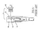
- a lock for this purpose generally includes a main body (50) having a plurality of dials (51) and a socket (52) for detachably receiving a separate hitching part (60).
- the dials (51) are required to be turned into the preset combination to allow the rear disk-like end of the part (60) to be placed into the socket (52) and fixedly attached to the main body (50).
- the lock is opened by turning the dials (51) into the presentcombination again before moving a slider (53) of the main body (50). It is at this time that the hitching part (60) can be detached from the main body (50).
- the object of the present invention is to provide a lock which is easy to be operated.
- Another object of the present invention is to provide a lock which is convenient to be well kept.
- a lock in accordance with the present invention includes a casing (30) having a front opening (32) and a hook (33) contiguous to the opening (32), with a wire cable (36) attached to a periphery of the casing (30).
- the casing (30) is further formed with a rear opening (31) for receiving a locking body (1).
- the locking body (1) includes a hollow body (10) received in the casing (30).
- the hollow body (10) has a rear chamber (11), a front through-hole (12) in alignment with the front opening (32) of the casing (30), and preferably a longitudinal groove (14) defined therein.
- a cylinder (20) is movably fitted in the rear chamber (11) of the hollow body (10).
- the cylinder (20) has a hole (23) for receiving a stud (15) that extends into and is movable along the longitudinal groove (14), thus ensuring the correct movement of the cylinder (20) between a front position, as shown in Fig. 4, and a rear position, as shown in Figs. 2 and 3, with respect to the hollow body (10) and hence to the casing (30).
- the cylinder (20) further has a forwardly extending stem (21) that has a rear end rotatably connected to the cylinder (20) and a front end rotatably connected to a bolt (26).
- the front end of the stem (21) is received in a rear blind hole (261) of the bolt (26) and is formed with a neck (24) defined by a frontmost disk (25), with a pin (27) extending into the neck (24) through an aperture (262) of the bolt (26), thereby allowing the front end of the stem (21) to be rotatably connecting to the bolt (26).
- the bolt (26) has a front lip (263) movable out of the casing (30) through the front opening (32), as best shown in Fig. 4. That is, the front lip (263) may be extended out of the casing (30) and securely held alongside the hook (33) when the cylinder (20) is moved to the front position. The front lip (263) may also be retracted into the casing (30) when the cylinder (20) is moved to the rear position by the action of a spring (28), which is accommodated in the rear chamber (11) of the hollow body (10) and is mounted around the stem (21) of the cylinder (20).
- the means for releasably keeping the lip include a pair of opposed cutouts (22) defined in a periphery of the stem (21) and a clip (17) received in a channel (13) of the hollow body (10).
- the channel (13) has a pair of straight portions (131) that communicate the front through-hole (12) substantially at two opposed tangential points, while the clip (17) is made into a U-shaped configuration and has a pair of shanks (171) resiliently flexible in the straight portions (131) of the channel (13).
- the inventive lock can be assembled simply by placing the locking body (1) into the rear opening (31) before the body (1) is fastened to the casing (30), such as by means of a pintle (35) which extends into aligned orifices (34, 16) of the casing (30) and the hollow body (10).
- the locking body (1) may be selected from any individual lock, known or not, which has a bolt adapted to be partially and retractably extended out, particularly one in which a bolt can be partially and retractably extended out by depressing a cylinder.
- the inventive lock is provided with a lot of choices of the locking body, as well as easiness in its assembly.
- the inventive lock is specially provided for securing an article (40) on display.
- the article (40) has a port (41) through which the hook (33) of the casing (30) can extend so as to hitch the article (40).
- the article (40) can be locked by depressing the cylinder (20), i.e. by moving it from the rear position to the front position. It is in the front position that the resilient shanks (171) of the U-shaped clip (17) snap into the cutouts (22) of the cylinder (20), thereby catching the stem (21) and hence keeping the lip (263) of the bolt (26) alongside the hook (33) of the casing (30).
- the lock can be opened only by turning the stem (21) relative to the cylinder (20), such as by means of a correct key (not shown) that is inserted into a keyslot defined in the cylinder (20). Now the shanks (171) are both pushed outward by the turning stem (21). When the shanks (171) fully slide out of the cutouts (22) and abut the periphery of the stem (21) again, the cylinder (20) will be moved quickly from its front position (Fig. 4) back to its rear position (Fig. 3) by the action of the compressed spring (28).
- the lip (263) of the bolt (26) is retracted into the casing (30) and the hook (33) may exit from the port (41) to allow the article (40) to be separated from the inventive lock.
- the clip (17) may be made in other configurations rather than the U-shaped one.
- an alternative clip made in an L-shaped configuration with one single shank can also be used.
- the channel (13) may be formed with only one straight portion which communicates the front through-hole (12) substantially at one tangential point, and the stem (21) may have only one cutout (22) defined therein.
- the L-shaped clip is received in the channel (13) with the single shank being resiliently flexible in the straight portion. Similar to the embodiment of the U-shaped configuration, the single shank normally abuts the periphery of the stem (21) but snaps into the cutout (22) and catches the stem (21) as soon as the cylinder (20) is moved to the front position.
- the inventive lock is easy to be operated.
- the hook (33) is formed integrally with the casing (33) and will not be lost in any way, the inventive lock is convenient to be well kept.
- the locking body may be selected from any individual lock which has a bolt adapted to be partially and retractably extended out, the inventive lock has choices of its locking body.
- the locking body (1) can be fastened to the casing (30) simply by inserting the pintle (35) into the aligned orifices (34, 16), the inventive lock is easy to be assembled.
Landscapes
- Supports Or Holders For Household Use (AREA)
Applications Claiming Priority (6)
| Application Number | Priority Date | Filing Date | Title |
|---|---|---|---|
| CN02241626 | 2002-06-26 | ||
| CN 02241626 CN2563261Y (zh) | 2002-07-04 | 2002-07-04 | 展示物件的锁具结构 |
| US201281 | 2002-07-24 | ||
| US10/201,281 US6591642B1 (en) | 2002-07-24 | 2002-07-24 | Lock for securing an article on display |
| JP2002353997 | 2002-12-05 | ||
| JP2002353997A JP2004183397A (ja) | 2002-12-05 | 2002-12-05 | 展示部品用の鎖 |
Publications (1)
| Publication Number | Publication Date |
|---|---|
| EP1384841A1 true EP1384841A1 (fr) | 2004-01-28 |
Family
ID=30003416
Family Applications (1)
| Application Number | Title | Priority Date | Filing Date |
|---|---|---|---|
| EP03253802A Ceased EP1384841A1 (fr) | 2002-06-26 | 2003-06-17 | Serrure de sécurité pour la présentation d'articles |
Country Status (1)
| Country | Link |
|---|---|
| EP (1) | EP1384841A1 (fr) |
Cited By (1)
| Publication number | Priority date | Publication date | Assignee | Title |
|---|---|---|---|---|
| EP3294973A4 (fr) * | 2015-05-12 | 2019-04-24 | Meir Avganim | Serrures de sécurité informatique à profil abaissé |
Citations (5)
| Publication number | Priority date | Publication date | Assignee | Title |
|---|---|---|---|---|
| US5447049A (en) * | 1994-01-31 | 1995-09-05 | Shieh; Jin-Ren | Push-button locking device |
| FR2741375A1 (fr) * | 1995-11-21 | 1997-05-23 | Ronis Sa | Serrure de condamnation a barillet a pene axial |
| US5799520A (en) * | 1996-03-07 | 1998-09-01 | The Eastern Company | Combined lock and linear actuator |
| US5913907A (en) * | 1998-04-30 | 1999-06-22 | Lee; Miko | Lock for securing a portable computer or the like |
| US6244082B1 (en) * | 1997-01-28 | 2001-06-12 | Meir Avganim | Portable computers lock |
-
2003
- 2003-06-17 EP EP03253802A patent/EP1384841A1/fr not_active Ceased
Patent Citations (5)
| Publication number | Priority date | Publication date | Assignee | Title |
|---|---|---|---|---|
| US5447049A (en) * | 1994-01-31 | 1995-09-05 | Shieh; Jin-Ren | Push-button locking device |
| FR2741375A1 (fr) * | 1995-11-21 | 1997-05-23 | Ronis Sa | Serrure de condamnation a barillet a pene axial |
| US5799520A (en) * | 1996-03-07 | 1998-09-01 | The Eastern Company | Combined lock and linear actuator |
| US6244082B1 (en) * | 1997-01-28 | 2001-06-12 | Meir Avganim | Portable computers lock |
| US5913907A (en) * | 1998-04-30 | 1999-06-22 | Lee; Miko | Lock for securing a portable computer or the like |
Cited By (1)
| Publication number | Priority date | Publication date | Assignee | Title |
|---|---|---|---|---|
| EP3294973A4 (fr) * | 2015-05-12 | 2019-04-24 | Meir Avganim | Serrures de sécurité informatique à profil abaissé |
Similar Documents
| Publication | Publication Date | Title |
|---|---|---|
| US7409842B2 (en) | Lock for securing an article on display | |
| US6591642B1 (en) | Lock for securing an article on display | |
| US6523378B2 (en) | Push-lock | |
| US6457751B1 (en) | Locking assembly for an astragal | |
| US7888572B2 (en) | Guitar strap lock | |
| US7562606B2 (en) | Multi-bit driver with removable and replaceable tool bits | |
| US6095386A (en) | Bicycle lock mounting bracket | |
| US6503262B1 (en) | Retractable micro-surgical tool | |
| KR20000076673A (ko) | 모듈러 부착 시스템 | |
| US6112373A (en) | Clasp assembly | |
| US20040126182A1 (en) | Connector | |
| US7493838B2 (en) | Multi-bit screwdriver | |
| US20050193531A1 (en) | Snap hook having lockable pivotal gate | |
| EP1001689B1 (fr) | Assembleur | |
| US20080250652A1 (en) | Self locking knife and sheath | |
| US6695365B2 (en) | Reversible lever detent spring mechanism | |
| US5031430A (en) | Key ring | |
| US6609271B2 (en) | Locking device for handle assembly with multiple stages | |
| US6471232B2 (en) | Locking device for a detachable bicycle top tube assembly | |
| EP1384841A1 (fr) | Serrure de sécurité pour la présentation d'articles | |
| US5875523A (en) | Belt and buckle arrangement | |
| US5517839A (en) | Detachable key ring | |
| CN116105546A (zh) | 能够操作为保持手枪的手枪枪套 | |
| US20050097712A1 (en) | Replaceable zipper pull | |
| AU2014344717B2 (en) | Multiple bit hand tool |
Legal Events
| Date | Code | Title | Description |
|---|---|---|---|
| PUAI | Public reference made under article 153(3) epc to a published international application that has entered the european phase |
Free format text: ORIGINAL CODE: 0009012 |
|
| AK | Designated contracting states |
Kind code of ref document: A1 Designated state(s): AT BE BG CH CY CZ DE DK EE ES FI FR GB GR HU IE IT LI LU MC NL PT RO SE SI SK TR |
|
| AX | Request for extension of the european patent |
Extension state: AL LT LV MK |
|
| 17P | Request for examination filed |
Effective date: 20040722 |
|
| AKX | Designation fees paid |
Designated state(s): AT BE BG CH CY CZ DE DK EE ES FI FR GB GR HU IE IT LI LU MC NL PT RO SE SI SK TR |
|
| 17Q | First examination report despatched |
Effective date: 20051123 |
|
| STAA | Information on the status of an ep patent application or granted ep patent |
Free format text: STATUS: THE APPLICATION HAS BEEN REFUSED |
|
| 18R | Application refused |
Effective date: 20080519 |