EP1384824A1 - Gyro wave-activated power generator and wave suppressor using the power generator - Google Patents
Gyro wave-activated power generator and wave suppressor using the power generator Download PDFInfo
- Publication number
- EP1384824A1 EP1384824A1 EP02713183A EP02713183A EP1384824A1 EP 1384824 A1 EP1384824 A1 EP 1384824A1 EP 02713183 A EP02713183 A EP 02713183A EP 02713183 A EP02713183 A EP 02713183A EP 1384824 A1 EP1384824 A1 EP 1384824A1
- Authority
- EP
- European Patent Office
- Prior art keywords
- wave
- gyro
- floating body
- power generator
- gimbal
- Prior art date
- Legal status (The legal status is an assumption and is not a legal conclusion. Google has not performed a legal analysis and makes no representation as to the accuracy of the status listed.)
- Granted
Links
Images



Classifications
-
- F—MECHANICAL ENGINEERING; LIGHTING; HEATING; WEAPONS; BLASTING
- F03—MACHINES OR ENGINES FOR LIQUIDS; WIND, SPRING, OR WEIGHT MOTORS; PRODUCING MECHANICAL POWER OR A REACTIVE PROPULSIVE THRUST, NOT OTHERWISE PROVIDED FOR
- F03B—MACHINES OR ENGINES FOR LIQUIDS
- F03B13/00—Adaptations of machines or engines for special use; Combinations of machines or engines with driving or driven apparatus; Power stations or aggregates
- F03B13/12—Adaptations of machines or engines for special use; Combinations of machines or engines with driving or driven apparatus; Power stations or aggregates characterised by using wave or tide energy
- F03B13/14—Adaptations of machines or engines for special use; Combinations of machines or engines with driving or driven apparatus; Power stations or aggregates characterised by using wave or tide energy using wave energy
- F03B13/16—Adaptations of machines or engines for special use; Combinations of machines or engines with driving or driven apparatus; Power stations or aggregates characterised by using wave or tide energy using wave energy using the relative movement between a wave-operated member, i.e. a "wom" and another member, i.e. a reaction member or "rem"
- F03B13/18—Adaptations of machines or engines for special use; Combinations of machines or engines with driving or driven apparatus; Power stations or aggregates characterised by using wave or tide energy using wave energy using the relative movement between a wave-operated member, i.e. a "wom" and another member, i.e. a reaction member or "rem" where the other member, i.e. rem is fixed, at least at one point, with respect to the sea bed or shore
-
- F—MECHANICAL ENGINEERING; LIGHTING; HEATING; WEAPONS; BLASTING
- F03—MACHINES OR ENGINES FOR LIQUIDS; WIND, SPRING, OR WEIGHT MOTORS; PRODUCING MECHANICAL POWER OR A REACTIVE PROPULSIVE THRUST, NOT OTHERWISE PROVIDED FOR
- F03B—MACHINES OR ENGINES FOR LIQUIDS
- F03B13/00—Adaptations of machines or engines for special use; Combinations of machines or engines with driving or driven apparatus; Power stations or aggregates
- F03B13/12—Adaptations of machines or engines for special use; Combinations of machines or engines with driving or driven apparatus; Power stations or aggregates characterised by using wave or tide energy
- F03B13/14—Adaptations of machines or engines for special use; Combinations of machines or engines with driving or driven apparatus; Power stations or aggregates characterised by using wave or tide energy using wave energy
- F03B13/16—Adaptations of machines or engines for special use; Combinations of machines or engines with driving or driven apparatus; Power stations or aggregates characterised by using wave or tide energy using wave energy using the relative movement between a wave-operated member, i.e. a "wom" and another member, i.e. a reaction member or "rem"
- F03B13/20—Adaptations of machines or engines for special use; Combinations of machines or engines with driving or driven apparatus; Power stations or aggregates characterised by using wave or tide energy using wave energy using the relative movement between a wave-operated member, i.e. a "wom" and another member, i.e. a reaction member or "rem" wherein both members, i.e. wom and rem are movable relative to the sea bed or shore
-
- F—MECHANICAL ENGINEERING; LIGHTING; HEATING; WEAPONS; BLASTING
- F05—INDEXING SCHEMES RELATING TO ENGINES OR PUMPS IN VARIOUS SUBCLASSES OF CLASSES F01-F04
- F05B—INDEXING SCHEME RELATING TO WIND, SPRING, WEIGHT, INERTIA OR LIKE MOTORS, TO MACHINES OR ENGINES FOR LIQUIDS COVERED BY SUBCLASSES F03B, F03D AND F03G
- F05B2220/00—Application
- F05B2220/70—Application in combination with
- F05B2220/706—Application in combination with an electrical generator
-
- F—MECHANICAL ENGINEERING; LIGHTING; HEATING; WEAPONS; BLASTING
- F05—INDEXING SCHEMES RELATING TO ENGINES OR PUMPS IN VARIOUS SUBCLASSES OF CLASSES F01-F04
- F05B—INDEXING SCHEME RELATING TO WIND, SPRING, WEIGHT, INERTIA OR LIKE MOTORS, TO MACHINES OR ENGINES FOR LIQUIDS COVERED BY SUBCLASSES F03B, F03D AND F03G
- F05B2240/00—Components
- F05B2240/90—Mounting on supporting structures or systems
- F05B2240/93—Mounting on supporting structures or systems on a structure floating on a liquid surface
-
- F—MECHANICAL ENGINEERING; LIGHTING; HEATING; WEAPONS; BLASTING
- F05—INDEXING SCHEMES RELATING TO ENGINES OR PUMPS IN VARIOUS SUBCLASSES OF CLASSES F01-F04
- F05B—INDEXING SCHEME RELATING TO WIND, SPRING, WEIGHT, INERTIA OR LIKE MOTORS, TO MACHINES OR ENGINES FOR LIQUIDS COVERED BY SUBCLASSES F03B, F03D AND F03G
- F05B2250/00—Geometry
- F05B2250/40—Movement of component
- F05B2250/44—Movement of component one element moving inside another one, e.g. wave-operated member (wom) moving inside another member (rem)
-
- Y—GENERAL TAGGING OF NEW TECHNOLOGICAL DEVELOPMENTS; GENERAL TAGGING OF CROSS-SECTIONAL TECHNOLOGIES SPANNING OVER SEVERAL SECTIONS OF THE IPC; TECHNICAL SUBJECTS COVERED BY FORMER USPC CROSS-REFERENCE ART COLLECTIONS [XRACs] AND DIGESTS
- Y02—TECHNOLOGIES OR APPLICATIONS FOR MITIGATION OR ADAPTATION AGAINST CLIMATE CHANGE
- Y02E—REDUCTION OF GREENHOUSE GAS [GHG] EMISSIONS, RELATED TO ENERGY GENERATION, TRANSMISSION OR DISTRIBUTION
- Y02E10/00—Energy generation through renewable energy sources
- Y02E10/30—Energy from the sea, e.g. using wave energy or salinity gradient
-
- Y—GENERAL TAGGING OF NEW TECHNOLOGICAL DEVELOPMENTS; GENERAL TAGGING OF CROSS-SECTIONAL TECHNOLOGIES SPANNING OVER SEVERAL SECTIONS OF THE IPC; TECHNICAL SUBJECTS COVERED BY FORMER USPC CROSS-REFERENCE ART COLLECTIONS [XRACs] AND DIGESTS
- Y10—TECHNICAL SUBJECTS COVERED BY FORMER USPC
- Y10S—TECHNICAL SUBJECTS COVERED BY FORMER USPC CROSS-REFERENCE ART COLLECTIONS [XRACs] AND DIGESTS
- Y10S415/00—Rotary kinetic fluid motors or pumps
- Y10S415/916—Perpetual motion devices
Definitions
- the present invention relates to a gyro wave-activated power generator utilizing wave energy which has, as a component, a control moment gyro.
- Wave power generation is a promising energy source. Wave power generation is being actively studied in Japan but the technology has not yet reached commercial levels.
- Wave-activated power generators using fluids are generally inefficient at generating electric power because of the severity of existing conditions like wave magnitude. Improving efficiency requires increasing the size of the system, which in turn means significant investments that the system uneconomical.
- the present invention intends to solve the above problems by offering a small-sized and efficient wave-activated power generator.
- the motion of a floating body on the sea is converted into energy by a control moment gyro to generate power.
- a wave suppressor using said power generator is also offered.
- the wave-activated power generator of the present invention comprises an enclosed gimbal, a flywheel which is set in the gimbal and turns on the spin shaft that is mounted at right angles to the gimbal shaft, a spin motor to turn the flywheel at high speed, and a power generator connected to the gimbal shaft via a gearing to increase speed, wherein the motion of the floating body produced by wave action is used to turn the gimbal to generate power.
- the system of the present invention is provided with a sensor to detect the inclination and angular velocity of the floating body and an encoder to detect the rotational angle and position of the gimbal.
- Signals from the sensor are used to synchronize the motion of the floating body with the rotation of the control moment gyro body for more efficient power generation.
- the efficiency of power generation is further enhanced by matching the gimbal rotation to the wave motion, which is basically a circular motion.
- the means of the technical solution offered by the present invention is a gyro wave-activated power generator that comprises a floating body, a control moment gyro supported on said floating body, and a power generator connected to the gimbal shaft of said gyro via gearing to increase speed, wherein the motion of the floating body produced by wave action is used to turn the gimbal of said gyro to generate power.
- the present invention further intends to provide a gyro wave-activated power generator wherein multiple control moment gyros are set on said floating body to generate power from each of the respective gyros.
- the present invention also intends to provide a gyro wave-activated power generator wherein ballast water is pumped into said floating body to change the natural frequency of the floating body to synchronize its frequency with the wave frequency.
- the present invention also intends to provide a gyro wave-activated power generator wherein the rotational speed of said gyro is controlled in such a manner that the rotation of the control moment gyro body synchronizes with the motion of said floating body.
- the present invention also provides a wave suppressor wherein multiple gyro wave-activated power generators of the present invention are arrayed on the water surface.
- the gyro wave-activated power generator of the present invention which comprises a control moment gyro, a power generator, and a controller, is described below referring to the attached drawings.
- Figure 1 is a cross-sectional view of the first working example of the power generator of the present invention.
- Figure 2 is an oblique view of the floating body used in the present invention.
- Figure 3 is the control block diagram.
- Figure 4 is the plan of a typical layout of an array of control moment gyros of the present invention.
- the main floating body (1) comprises two floating sub-bodies (1A) which are connected by two members (1B).
- the control moment gyro power generator which is described later, is positioned at the center of the bottom (2) of said square floating body.
- the main floating body (1) is fixed to the sea bottom with anchors (3).
- the main floating body (1) may not necessarily be square in shape but may also be of any other shape that can resist possible overturning, such as a ship-like, circular, or polygonal shape.
- Two gimbal shaft bearings (4) are installed at the center of the bottom (2) of the main floating body (1) to support the control moment gyro (5) on both sides.
- the gimbal shafts (6a and 6b) of the control moment gyro (5) rest and turn freely on said gimbal shaft bearings (4).
- the gimbal (6) is a sealed cylindrical vessel, in which a flywheel (7) is mounted and rotates freely on the spin shaft (7a).
- Said spin shaft (7a) is installed at right angles to said gimbal shafts (6a and 6b).
- a spin motor (8) is installed on the spin shaft (7a) of the flywheel (7).
- the spin motor (8) is set within or on the outside of the vessel and is sealed to prevent air from entering the vessel.
- the sealed vessel forming the gimbal (6) is connected to a vacuum pump (not shown).
- This negative pressure pump is used to reduce the pressure inside the gimbal (6) to, for example, 0.1 atmospheric pressure or below to decrease flywheel drag (7) and windage loss.
- the gimbal (6) is connected, on the gimbal shaft (6b) side, to the power generator (10) via gearing to increase speed (9) that comprises a gear mechanism and others so that power is generated as the gimbal (6) rotates.
- the power generator (10) is connected, regardless of the direction the gimbal (6) rotates, to a power converter (not shown) or a condenser (not shown) via a compatible rectifier.
- the shaft (6a) on the other side of the gimbal (6) accommodates the spin motor (8) and brushes (11) that supply power to the vacuum pump motor. These units are connected to a power supply.
- a brake may also be installed to stop the flywheel in the event of an emergency such as an accident.
- the power generator (10) is mounted on a base (12) on the bottom of the main floating body.
- the control moment gyro is similar to conventional units in terms of its basic structure and operation, and therefore a description of its operating principle is omitted here.
- the main floating body (1) is equipped with a controller (13) to control power and the power generator.
- the main floating body (1) is also fitted with a pump (not shown) and a valve (not shown) to adjust the volume of ballast water pumped into the floating body. By adjusting the volume of ballast water, the natural frequency of the floating body can be synchronized with the wave frequency.
- the main floating body (1) is also provided with a motion sensor (14) to detect the inclination and angular speed of the main floating body (1) and an encoder (15) (a sensor to detect the direction of the gimbal shaft) to detect the angle of rotation and the position of the gimbal (6). These sensors are electrically connected to the controller (13) mounted on the main floating body (1).
- the generator and other equipment mounted on the main floating body (1) are protected from sea water spray and splashing by a cover (16).
- the gyro wave-activated power generator is set on the sea surface with the flywheel (7) driven by the spin motor (8) and rotating at high speed.
- the motion (inclination) of the main floating body (1) caused by wave action is transferred to the control moment gyro (5) to turn the gimbal (6) and drive the generator (10) via gearing to increase speed (9) to generate power.
- the generated power is stored in a condenser or supplied directly to operate an actuator.
- the controller uses signals from the motion sensor (14) to detect the inclination and angular speed of the main floating body (1) and the encoder (15) (sensor to detect the direction of the gimbal shaft) to detect the rotation angle and position of the gimbal (6).
- the controller synchronizes the motion of the floating body with the rotation of the control moment gyro body using the circuit shown in the control block diagram in Fig. 3.
- the speed of the gyro (6) is controlled on the generator side to generate power most efficiently. Ballast water is pumped into the floating body (1) at a controlled volume to synchronize the natural frequency of the floating body motion to the wave frequency to further enhance power generation efficiency. This system is particularly effective when wave magnitude and frequency differ during the summer and winter seasons.
- the power generating efficiency of the CMG system (gyro wave-activated power generation) of the present invention was compared with the output from an existing floating body air turbine type system. The result of a typical example is shown below.
- the synthesized efficiency ⁇ T was 0.43 to 0.77.
- the synthesized efficiency ⁇ T was 0.10 to 0.39.
- Stages (1) and (5) are common in both cases, indicating that the turbine is responsible for the deteriorated efficiency.
- Wave action is basically a circular motion. It is preferable to have the gimbal rotate in the same basic direction as said circular wave motion and set the gyro body at an angle to the incoming wave direction.
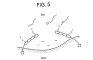
- Two or more wave-activated power generators of the present invention may be arrayed to form a sort of breakwater as shown in Fig. 5 to construct a wave suppressor that creates a calm sea area.
- the gyro wave-activated power generator of the present invention captures the motion of a floating body on the sea with a control moment gyro, and it generates electric power efficiently using the captured energy. It is possible to reduce flywheel resistance in the gimbal by maintaining the inside of the sealed gimbal enclosure, a component of the present invention, at a negative pressure using a vacuum pump. This decreases the energy to drive the spin motor. Multiple sets of control moment gyros may be installed on a single floating body to prevent unwanted motion of the floating body and generate electric power efficiently. Power generating efficiency can be improved by synchronizing the natural frequency of the floating body motion to the wave frequency by pumping ballast water into the floating body at a controlled volume. Multiple floating bodies equipped with power generators may be arrayed to form a sort of breakwater to be used as wave suppressor to create a calm sea area. These are some of the excellent effects of the present invention and its embodiments.
Landscapes
- Engineering & Computer Science (AREA)
- Chemical & Material Sciences (AREA)
- Combustion & Propulsion (AREA)
- Mechanical Engineering (AREA)
- General Engineering & Computer Science (AREA)
- Other Liquid Machine Or Engine Such As Wave Power Use (AREA)
- Revetment (AREA)
Abstract
Description
Claims (5)
- A gyro wave-activated power generator that comprises a floating body, a control moment gyro supported by said floating body, and a power generator connected to the gimbal shaft of said gyro via gearing to increase speed wherein the gimbal of said gyro is rotated by the motion of said floating body produced by wave action which drives said power generator to generate power.
- A gyro wave-activated power generator as claimed in claim 1 wherein said floating body is provided with multiple control moment gyros, each of which generates power.
- A gyro wave-activated power generator as claimed in claim 1 or 2 wherein ballast water is pumped into said floating body to synchronize the natural frequency of the floating body to the wave frequency.
- A gyro wave-activated power generator as claimed in claim 1, 2 or 3 wherein the gyro speed is controlled to synchronize the motion of the floating body with the rotation of the control moment gyro.
- A wave suppressor comprising multiple gyro wave-activated power generators as claimed in claim 1, 2, 3, or 4 wherein said multiple power generators are arrayed on the surface of the sea.
Applications Claiming Priority (3)
| Application Number | Priority Date | Filing Date | Title |
|---|---|---|---|
| JP2001088011 | 2001-03-26 | ||
| JP2001088011 | 2001-03-26 | ||
| PCT/JP2002/002775 WO2002077369A1 (en) | 2001-03-26 | 2002-03-22 | Gyro wave-activated power generator and wave suppressor using the power generator |
Publications (3)
| Publication Number | Publication Date |
|---|---|
| EP1384824A1 true EP1384824A1 (en) | 2004-01-28 |
| EP1384824A4 EP1384824A4 (en) | 2005-01-05 |
| EP1384824B1 EP1384824B1 (en) | 2006-05-24 |
Family
ID=18943168
Family Applications (1)
| Application Number | Title | Priority Date | Filing Date |
|---|---|---|---|
| EP02713183A Expired - Lifetime EP1384824B1 (en) | 2001-03-26 | 2002-03-22 | Gyro wave-activated power generator and wave suppressor using the power generator |
Country Status (6)
| Country | Link |
|---|---|
| US (1) | US7003947B2 (en) |
| EP (1) | EP1384824B1 (en) |
| JP (1) | JP4184803B2 (en) |
| DE (1) | DE60211682T2 (en) |
| DK (1) | DK1384824T3 (en) |
| WO (1) | WO2002077369A1 (en) |
Cited By (8)
| Publication number | Priority date | Publication date | Assignee | Title |
|---|---|---|---|---|
| GB2418707A (en) * | 2004-08-02 | 2006-04-05 | Timothy Andrew Sparrow | Device for producing energy from wave motion incorporating a gyroscope |
| WO2008040822A1 (en) * | 2006-10-03 | 2008-04-10 | Oceantec Energías Marinas, S.L. | Installation and method for harnessing wave energy using gyroscope |
| WO2008097116A3 (en) * | 2007-02-05 | 2008-09-25 | Jose Manuel Braga Albuquerque | A submerged waterproof wave energy converter with gyroscope power- take-off |
| ITTO20090422A1 (en) * | 2009-06-04 | 2010-12-05 | Torino Politecnico | MARINE ENERGY CONVERTER |
| GB2473659A (en) * | 2009-09-19 | 2011-03-23 | Bruce Gregory | Dynamically tuned wave energy converter |
| ITTO20110879A1 (en) * | 2011-10-03 | 2013-04-04 | Noomen Technologies S R L | ELECTRIC POWER GENERATOR SYSTEM FROM THE SEA MOTO MOTION |
| EP2315935A4 (en) * | 2008-05-30 | 2013-05-01 | Ocean Power Technologies Inc | ADVANCED CONTROL OF HOMELOMOTEUR DEVICE |
| EP2593667A4 (en) * | 2010-07-15 | 2017-06-21 | Wello Oy | Wave power plant |
Families Citing this family (34)
| Publication number | Priority date | Publication date | Assignee | Title |
|---|---|---|---|---|
| US7267677B2 (en) * | 1998-10-23 | 2007-09-11 | Sherwood Services Ag | Vessel sealing instrument |
| JP4469620B2 (en) * | 2004-01-23 | 2010-05-26 | 博 神吉 | Gyro wave power generator |
| FR2876751B1 (en) | 2004-10-15 | 2007-01-19 | Centre Nat Rech Scient Cnrse | APPARATUS FOR CONVERTING WAVE ENERGY INTO ELECTRICAL ENERGY |
| US7375436B1 (en) * | 2004-11-12 | 2008-05-20 | Aaron Goldin | Gyroscope-based electricity generator |
| US20070018458A1 (en) * | 2005-07-22 | 2007-01-25 | Martinez Melaquias E | Method and apparatus for wave energy conversion using a floating pulley and counterweight |
| US8519557B2 (en) | 2005-11-07 | 2013-08-27 | Gwave Llc | System for producing energy through the action of waves |
| US8915078B2 (en) * | 2005-11-07 | 2014-12-23 | Gwave Llc | System for producing energy through the action of waves |
| US9976535B2 (en) | 2005-11-07 | 2018-05-22 | Gwave Llc | System for producing energy through the action of waves |
| US8701403B2 (en) * | 2005-11-07 | 2014-04-22 | Gwave Llc | System for producing energy through the action of waves |
| AU2006202066A1 (en) * | 2006-05-17 | 2007-12-06 | Voropaev, Ivan Mr | OWC Power Plant |
| JP4810662B2 (en) | 2006-05-25 | 2011-11-09 | 国立大学法人神戸大学 | Wave power generation system and wave power generation plant |
| JP4821008B2 (en) * | 2007-03-19 | 2011-11-24 | 国立大学法人神戸大学 | Wave power generation system and wave power generation plant |
| US20100058882A1 (en) * | 2008-09-07 | 2010-03-11 | Frederick William Klatt | Oscillating or Low Speed Electric Machine Apparatus |
| JP2011190764A (en) * | 2010-03-16 | 2011-09-29 | Ntn Corp | Gyro wave-activated power generator |
| GB2484324A (en) * | 2010-10-07 | 2012-04-11 | Adnan Mansoor | Power generating apparatus for a vessel, eg a ship or boat |
| DK201100073A (en) | 2011-02-06 | 2012-08-07 | JOLTECH ApS | Gyroscopic device for converting mechanical wave energy into electrical energy |
| WO2013156674A2 (en) | 2012-04-17 | 2013-10-24 | Wello Oy | Method for converting the energy of water waves into electricity by means of a wave power plant and a wave power plant |
| FI123295B (en) | 2011-11-17 | 2013-02-15 | Wello Oy | Wave power |
| FI20116152A7 (en) | 2011-11-17 | 2013-05-18 | Wello Oy | Wave power plant |
| DE102011119384B3 (en) * | 2011-11-25 | 2013-03-28 | Voith Patent Gmbh | Hydroelectric power plant and primary control of a hydroelectric power plant |
| PE20150225A1 (en) | 2012-06-04 | 2015-02-22 | Gwave Llc | ENERGY PRODUCTION SYSTEM THROUGH THE ACTION OF WAVES |
| FI124102B (en) | 2012-06-27 | 2014-03-14 | Wello Oy | Wave power |
| GB2508399B (en) * | 2012-11-30 | 2015-04-29 | Univ Southampton | Marine vehicle using a gyroscopic system to generate power for a propulsion system |
| US10947951B2 (en) * | 2015-06-28 | 2021-03-16 | Vassilios Vamvas | Eccentrically rotating mass turbine |
| CN106401846A (en) * | 2015-12-22 | 2017-02-15 | 刘贤龙 | Device for generating power through flowing potential energy of river water flow |
| US11121613B2 (en) * | 2017-05-19 | 2021-09-14 | Craig H. Zeyher | Dynamic electrical generator and its associated method of operation |
| DK179738B1 (en) | 2017-10-11 | 2019-04-30 | Ravn Niels | Wind-Driven Energy Converting Device |
| KR101868837B1 (en) * | 2017-11-24 | 2018-06-20 | 주식회사 로고스웨어 | Capsule buoy type of wave energy converter |
| KR102386008B1 (en) * | 2017-12-06 | 2022-04-12 | 폴리테크니코 디 토리노 | A system that generates electrical energy from waves in the ocean |
| CN109267538B (en) * | 2018-11-20 | 2019-05-31 | 江苏科技大学 | A typhoon-resistant floating breakwater system and its control method |
| US12066000B2 (en) * | 2021-04-01 | 2024-08-20 | Exmar Offshore Company | Smart wave energy converter with adaptive motion response |
| US11821158B2 (en) * | 2021-07-12 | 2023-11-21 | X Development Llc | Autonomous modular breakwater system |
| WO2024064232A1 (en) * | 2022-09-22 | 2024-03-28 | X Development Llc | Method and system of adaptive lensing for sea waves |
| US12601326B2 (en) | 2023-05-09 | 2026-04-14 | Craig H. Zeyher | Torque driven dynamic generator with inertia sustaining drive |
Family Cites Families (11)
| Publication number | Priority date | Publication date | Assignee | Title |
|---|---|---|---|---|
| GB191403691A (en) * | 1914-02-12 | 1915-03-18 | Us Wave Power Company | Improvements in Wave Motors. |
| FR2474601A1 (en) * | 1980-01-29 | 1981-07-31 | Gach Alain | Gyroscopic energy converter utilising roll and pitch of ship - uses large gyroscope vertical axis creating precession which causes shaft to oscillate and drive generator |
| US4352023A (en) * | 1981-01-07 | 1982-09-28 | Sachs Herbert K | Mechanism for generating power from wave motion on a body of water |
| FR2511438A1 (en) * | 1981-08-13 | 1983-02-18 | Floure Jacques | Wave energy converter for electricity generator - uses vertical rack fixed to sea bed with movement of chassis carried on floats at which arms pressurise hydraulic motor |
| GB9021969D0 (en) * | 1990-10-09 | 1990-11-21 | Greer Robin | Apparatus for extracting energy from an oscillating energy source |
| JPH05164036A (en) | 1991-12-13 | 1993-06-29 | Mitsubishi Heavy Ind Ltd | Barge type platform for wave activated power generation |
| JPH06280240A (en) | 1993-03-30 | 1994-10-04 | Mitsubishi Heavy Ind Ltd | Piezoelectric element oscillation type wave-activated power generation apparatus |
| JP3377590B2 (en) | 1994-02-08 | 2003-02-17 | 三菱重工業株式会社 | Power generation offshore structure |
| JPH07333664A (en) | 1994-06-06 | 1995-12-22 | Olympus Optical Co Ltd | Camera |
| US6561856B1 (en) * | 2001-02-07 | 2003-05-13 | Vladislav Vasilyevich Gorshkov | Power floating production and ship propulsion supported by gyroscope and energized by seas |
| US6888262B2 (en) * | 2003-02-03 | 2005-05-03 | General Electric Company | Method and apparatus for wind turbine rotor load control |
-
2002
- 2002-03-22 EP EP02713183A patent/EP1384824B1/en not_active Expired - Lifetime
- 2002-03-22 DE DE60211682T patent/DE60211682T2/en not_active Expired - Lifetime
- 2002-03-22 DK DK02713183T patent/DK1384824T3/en active
- 2002-03-22 US US10/472,224 patent/US7003947B2/en not_active Expired - Fee Related
- 2002-03-22 JP JP2002575397A patent/JP4184803B2/en not_active Expired - Fee Related
- 2002-03-22 WO PCT/JP2002/002775 patent/WO2002077369A1/en not_active Ceased
Cited By (14)
| Publication number | Priority date | Publication date | Assignee | Title |
|---|---|---|---|---|
| GB2418707A (en) * | 2004-08-02 | 2006-04-05 | Timothy Andrew Sparrow | Device for producing energy from wave motion incorporating a gyroscope |
| US7906865B2 (en) | 2006-10-03 | 2011-03-15 | Oceantec Energias Marinas, S.L. | Installation and method for harnessing wave energy |
| WO2008040822A1 (en) * | 2006-10-03 | 2008-04-10 | Oceantec Energías Marinas, S.L. | Installation and method for harnessing wave energy using gyroscope |
| AU2006349157B2 (en) * | 2006-10-03 | 2011-09-29 | Oceantec Energias Marinas, S.L. | Installation and method for harnessing wave energy using gyroscope |
| WO2008097118A3 (en) * | 2007-02-05 | 2009-11-19 | Albuquerque Jose Manuel Braga | A submerged waterproof wave energy converter with gyroscope power take-off |
| WO2008097116A3 (en) * | 2007-02-05 | 2008-09-25 | Jose Manuel Braga Albuquerque | A submerged waterproof wave energy converter with gyroscope power- take-off |
| EP2315935A4 (en) * | 2008-05-30 | 2013-05-01 | Ocean Power Technologies Inc | ADVANCED CONTROL OF HOMELOMOTEUR DEVICE |
| WO2010140113A1 (en) * | 2009-06-04 | 2010-12-09 | Politecnico Di Torino | Wave energy converter |
| ITTO20090422A1 (en) * | 2009-06-04 | 2010-12-05 | Torino Politecnico | MARINE ENERGY CONVERTER |
| GB2473659A (en) * | 2009-09-19 | 2011-03-23 | Bruce Gregory | Dynamically tuned wave energy converter |
| GB2473659B (en) * | 2009-09-19 | 2012-04-11 | Bruce Gregory | Dynamically tuned wave energy conversion system |
| EP2593667A4 (en) * | 2010-07-15 | 2017-06-21 | Wello Oy | Wave power plant |
| ITTO20110879A1 (en) * | 2011-10-03 | 2013-04-04 | Noomen Technologies S R L | ELECTRIC POWER GENERATOR SYSTEM FROM THE SEA MOTO MOTION |
| WO2013050924A1 (en) * | 2011-10-03 | 2013-04-11 | Wave For Energy S.R.L. | System for generating electrical energy from sea waves |
Also Published As
| Publication number | Publication date |
|---|---|
| JP4184803B2 (en) | 2008-11-19 |
| JPWO2002077369A1 (en) | 2004-07-15 |
| US20040134190A1 (en) | 2004-07-15 |
| DK1384824T3 (en) | 2006-08-14 |
| EP1384824B1 (en) | 2006-05-24 |
| EP1384824A4 (en) | 2005-01-05 |
| WO2002077369A1 (en) | 2002-10-03 |
| DE60211682T2 (en) | 2007-04-26 |
| DE60211682D1 (en) | 2006-06-29 |
| US7003947B2 (en) | 2006-02-28 |
Similar Documents
| Publication | Publication Date | Title |
|---|---|---|
| US7003947B2 (en) | Gyro wave activated power generator and a wave suppressor using the power generator | |
| JP5410636B2 (en) | Direct drive wave energy converter | |
| US7686583B2 (en) | Cyclical wave energy converter | |
| US6731018B1 (en) | Water generator oscillating due to rapid flow of fluid | |
| WO2005071257A1 (en) | Gyro wave-power generator | |
| EP1589643B1 (en) | Magnetic force transmission | |
| US4352023A (en) | Mechanism for generating power from wave motion on a body of water | |
| US10378507B2 (en) | Fluid flow induced oscillating energy harvester with variable damping based upon oscillation amplitude | |
| JP5579735B2 (en) | Platform for capturing wave energy | |
| GB2462663A (en) | Gyroscopic energy converter with rotor accelerated via one way clutch | |
| CN116928031B (en) | Wind turbine foundations, wind turbine generator sets, and control methods | |
| JPH06280732A (en) | Piezoelectric element flexing wave activated power generating set | |
| GB2410299A (en) | An ocean power converter | |
| GB2409898A (en) | A rocking motion energy converter | |
| CN102705147B (en) | Wave energy converting device | |
| KR101492768B1 (en) | Floating wave power generation device using the cross flow turbine | |
| JPH08177710A (en) | Power generating device | |
| WO2005071258A1 (en) | Arrangement for utilizing wave power | |
| CN212583871U (en) | A low-frequency and frequency-adjustable float-type wave power generation device | |
| WO2023105410A1 (en) | Pendular gyroscopic device for energy conversion, and system for the generation of electric energy comprising such device | |
| CN121803386A (en) | An ultra-low frequency inertial pendulum wave energy generation device based on a magnetic array | |
| AU2015200380A1 (en) | Direct drive rotary wave energy conversion |
Legal Events
| Date | Code | Title | Description |
|---|---|---|---|
| PUAI | Public reference made under article 153(3) epc to a published international application that has entered the european phase |
Free format text: ORIGINAL CODE: 0009012 |
|
| 17P | Request for examination filed |
Effective date: 20031027 |
|
| AK | Designated contracting states |
Kind code of ref document: A1 Designated state(s): AT BE CH CY DE DK ES FI FR GB GR IE IT LI LU MC NL PT SE TR |
|
| AX | Request for extension of the european patent |
Extension state: AL LT LV MK RO SI |
|
| A4 | Supplementary search report drawn up and despatched |
Effective date: 20041122 |
|
| 17Q | First examination report despatched |
Effective date: 20050321 |
|
| GRAP | Despatch of communication of intention to grant a patent |
Free format text: ORIGINAL CODE: EPIDOSNIGR1 |
|
| RBV | Designated contracting states (corrected) |
Designated state(s): DE DK FR GB NL |
|
| GRAS | Grant fee paid |
Free format text: ORIGINAL CODE: EPIDOSNIGR3 |
|
| GRAA | (expected) grant |
Free format text: ORIGINAL CODE: 0009210 |
|
| AK | Designated contracting states |
Kind code of ref document: B1 Designated state(s): DE DK FR GB NL |
|
| REG | Reference to a national code |
Ref country code: GB Ref legal event code: FG4D |
|
| RAP2 | Party data changed (patent owner data changed or rights of a patent transferred) |
Owner name: JAPAN SCIENCE AND TECHNOLOGY AGENCY |
|
| REF | Corresponds to: |
Ref document number: 60211682 Country of ref document: DE Date of ref document: 20060629 Kind code of ref document: P |
|
| NLT2 | Nl: modifications (of names), taken from the european patent patent bulletin |
Owner name: JAPAN SCIENCE AND TECHNOLOGY AGENCY Effective date: 20060531 |
|
| REG | Reference to a national code |
Ref country code: DK Ref legal event code: T3 |
|
| ET | Fr: translation filed | ||
| PLBE | No opposition filed within time limit |
Free format text: ORIGINAL CODE: 0009261 |
|
| STAA | Information on the status of an ep patent application or granted ep patent |
Free format text: STATUS: NO OPPOSITION FILED WITHIN TIME LIMIT |
|
| 26N | No opposition filed |
Effective date: 20070227 |
|
| NLXE | Nl: other communications concerning ep-patents (part 3 heading xe) |
Free format text: PAT. BUL. 08/2006: CORR.: JAPAN SCIENCE AND TECHNOLOGY AGENCY. |
|
| REG | Reference to a national code |
Ref country code: GB Ref legal event code: 732E |
|
| NLS | Nl: assignments of ep-patents |
Owner name: HIROSHI KANKI Effective date: 20080610 |
|
| REG | Reference to a national code |
Ref country code: FR Ref legal event code: TP |
|
| PGFP | Annual fee paid to national office [announced via postgrant information from national office to epo] |
Ref country code: FR Payment date: 20140331 Year of fee payment: 13 Ref country code: DE Payment date: 20140401 Year of fee payment: 13 Ref country code: NL Payment date: 20140331 Year of fee payment: 13 |
|
| PGFP | Annual fee paid to national office [announced via postgrant information from national office to epo] |
Ref country code: DK Payment date: 20150324 Year of fee payment: 14 |
|
| REG | Reference to a national code |
Ref country code: DE Ref legal event code: R119 Ref document number: 60211682 Country of ref document: DE |
|
| REG | Reference to a national code |
Ref country code: NL Ref legal event code: MM Effective date: 20150401 |
|
| REG | Reference to a national code |
Ref country code: FR Ref legal event code: ST Effective date: 20151130 |
|
| PG25 | Lapsed in a contracting state [announced via postgrant information from national office to epo] |
Ref country code: DE Free format text: LAPSE BECAUSE OF NON-PAYMENT OF DUE FEES Effective date: 20151001 |
|
| PG25 | Lapsed in a contracting state [announced via postgrant information from national office to epo] |
Ref country code: FR Free format text: LAPSE BECAUSE OF NON-PAYMENT OF DUE FEES Effective date: 20150331 |
|
| PGFP | Annual fee paid to national office [announced via postgrant information from national office to epo] |
Ref country code: GB Payment date: 20160318 Year of fee payment: 15 |
|
| REG | Reference to a national code |
Ref country code: DK Ref legal event code: EBP Effective date: 20160331 |
|
| PG25 | Lapsed in a contracting state [announced via postgrant information from national office to epo] |
Ref country code: DK Free format text: LAPSE BECAUSE OF NON-PAYMENT OF DUE FEES Effective date: 20160331 |
|
| PG25 | Lapsed in a contracting state [announced via postgrant information from national office to epo] |
Ref country code: NL Free format text: LAPSE BECAUSE OF NON-PAYMENT OF DUE FEES Effective date: 20150401 |
|
| GBPC | Gb: european patent ceased through non-payment of renewal fee |
Effective date: 20170322 |
|
| PG25 | Lapsed in a contracting state [announced via postgrant information from national office to epo] |
Ref country code: GB Free format text: LAPSE BECAUSE OF NON-PAYMENT OF DUE FEES Effective date: 20170322 |