EP1384616A2 - Seal configuration, in particular for the sealing of a movable window pane for a vehicle - Google Patents
Seal configuration, in particular for the sealing of a movable window pane for a vehicle Download PDFInfo
- Publication number
- EP1384616A2 EP1384616A2 EP03102244A EP03102244A EP1384616A2 EP 1384616 A2 EP1384616 A2 EP 1384616A2 EP 03102244 A EP03102244 A EP 03102244A EP 03102244 A EP03102244 A EP 03102244A EP 1384616 A2 EP1384616 A2 EP 1384616A2
- Authority
- EP
- European Patent Office
- Prior art keywords
- seal
- sealing
- section
- tab
- flange
- Prior art date
- Legal status (The legal status is an assumption and is not a legal conclusion. Google has not performed a legal analysis and makes no representation as to the accuracy of the status listed.)
- Granted
Links
Images

Classifications
-
- B—PERFORMING OPERATIONS; TRANSPORTING
- B60—VEHICLES IN GENERAL
- B60J—WINDOWS, WINDSCREENS, NON-FIXED ROOFS, DOORS, OR SIMILAR DEVICES FOR VEHICLES; REMOVABLE EXTERNAL PROTECTIVE COVERINGS SPECIALLY ADAPTED FOR VEHICLES
- B60J10/00—Sealing arrangements
- B60J10/70—Sealing arrangements specially adapted for windows or windscreens
- B60J10/74—Sealing arrangements specially adapted for windows or windscreens for sliding window panes, e.g. sash guides
- B60J10/75—Sealing arrangements specially adapted for windows or windscreens for sliding window panes, e.g. sash guides for sealing the lower part of the panes
-
- B—PERFORMING OPERATIONS; TRANSPORTING
- B60—VEHICLES IN GENERAL
- B60J—WINDOWS, WINDSCREENS, NON-FIXED ROOFS, DOORS, OR SIMILAR DEVICES FOR VEHICLES; REMOVABLE EXTERNAL PROTECTIVE COVERINGS SPECIALLY ADAPTED FOR VEHICLES
- B60J10/00—Sealing arrangements
- B60J10/30—Sealing arrangements characterised by the fastening means
- B60J10/32—Sealing arrangements characterised by the fastening means using integral U-shaped retainers
Definitions
- the invention relates to a sealing arrangement, in particular for sealing a movable window pane of a motor vehicle is used.
- the seal arrangement Comes with a body part and a gasket that has a gasket section and a fixing portion provided. To the Attachment section is arranged a tab which is form-fitting with the Body part is connected.
- a sealing arrangement for sealing a movable window pane of a motor vehicle is described in EP 0 482 999 B1.
- the well-known Sealing arrangement comprises a seal which approximates one in cross section Has U-shaped designed attachment portion.
- the attachment section is attached to a flange of the body of the motor vehicle.
- One connected to the attachment portion hook-shaped projection engages in an opening of the flange to additionally lock the seal.
- the base portion and the tabs are integrally formed by injection molding manufactured and connected to the manufactured by extrusion seal section, so that the base portion and the tabs of one and the same consist rigid material.
- the deformability of the tabs is through achieved the design in the region of the slot.
- the sealing arrangement according to the invention is based on the knowledge, the attachment section positively to connect to the body part to a to achieve reliable attachment of the seal to the body part. Of the Positive engagement increases the pull-off force required to seal the seal remove the body part. In this way, the tab contributes to a effective protection against, for example, burglary. It also acts it is a tab to a structurally simple component, the can be manufactured inexpensively.
- the arranged on the attachment portion Tab also allows easy installation, for example, with the body part is locked.
- tabs that are different from each other spaced apart at the attachment portion are arranged.
- the withdrawal force is further increased by the provision of multiple tabs.
- you can the tabs are relatively small in this way, whereby the assembly is facilitated.
- the tabs extend expediently in the longitudinal direction of the seal and are arranged equidistant to to produce a uniform pull-off force along the seal.
- the attachment portion is by a preferably metallic Arm reinforced.
- the carrier ensures sufficient rigidity the fastening portion and thus contributes to a reliable attachment at.
- the seal of an elastically deformable material, preferably a thermoplastic elastomer or ethylene-propylene-diene rubber (EPDM), extruded.
- EPDM ethylene-propylene-diene rubber
- the tab is either made in one piece with the seal or cohesively, preferably by injection molding, with the attachment portion connected.
- the seal and the tab can be easily and cost-effective manner. If the tab is about by injection molding connected after the extrusion of the seal with the attachment portion, it has been found to be particularly advantageous for the tab one thermoplastic, preferably polyethylene (PE) provided.
- PE polyethylene
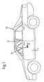
- the motor vehicle 10 shown in Fig. 1 is provided with a door 11, the has a frame 12. Within the frame 12 is a windowpane 13 arranged movable. The window pane 13 is replaced by a seal 20th sealed, which is fixed to a flange 15 of the door 11. To this end has the seal 20 adjacent to one of the window pane 13 Seal portion 21 on a mounting portion 22 which in cross section is designed approximately U-shaped.
- the attachment portion 22 has a Recess 26, which is plugged onto the flange 15, in particular from Fig. 2 can be seen. In the recess 26 retaining lips 27 are arranged, the connect the attachment portion 22 frictionally with the flange 15.
- the attachment section 22 is in the region of Recess 26 by a plastic or metal existing carrier 23rd reinforced, which has a cross-sectionally approximately U-shaped configuration.
- the carrier 23 is used to that of EPDM existing and elastically deformable Seal 20 in the region of the mounting portion 22 a sufficient To confer rigidity, which results in a frictional attachment of the seal 20 contributes to the flange 15 by means of the retaining lips 27.
- To be a reliable and to ensure permanent attachment are at least in the area of one the window glass 13 receiving shaft of the door 11 at the attachment portion 22 a plurality of tabs 30 are arranged, which has an opening 31 have.
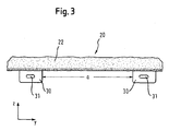
- the spaced apart at a distance a tabs 30th extend in the longitudinal direction y of the seal 20, as Fig. 3 reveals.
- the tabs 30 are integrally formed by injection molding with the attachment portion 22 connected.
- the tabs 30 consist of a comparatively hard thermoplastic, for example polyethylene, on the one hand a fast and permanent material connection with the EPDM existing seal 20 ensures and the other of the tab 30th gives sufficient rigidity.
- the tabs 30 can also be made in one piece with the seal 20, for example by extrusion.
- the sealing arrangement described above is characterized by a reliable Attachment of the seal 20 to the flange 15 of the door 11 from. reason For this purpose, especially the tabs 30, a positive connection between the Seal 20 and the flange 15 effect.
- the seal can be 20 easily attach to the flange 15 by putting on the recess 26 on the flange 15 of the projection 14 in the opening 31 of the tabs 30 engages.
- the tabs 30 are injection molded cohesively with the mounting portion 22 of the extruded seal 20th connected, so that not least a cost-effective production bill will be carried.
Abstract
Description
Die Erfindung betrifft eine Dichtungsanordnung, die insbesondere zum Abdichten einer verfahrbaren Fensterscheibe eines Kraftfahrzeugs dient. Die Dichtungsanordnung ist mit einem Karosserieteil und einer Dichtung, die einen Dichtungsabschnitt und einen Befestigungsabschnitt aufweist, versehen. An dem Befestigungsabschnitt ist eine Lasche angeordnet, die formschlüssig mit dem Karosserieteil verbunden ist.The invention relates to a sealing arrangement, in particular for sealing a movable window pane of a motor vehicle is used. The seal arrangement Comes with a body part and a gasket that has a gasket section and a fixing portion provided. To the Attachment section is arranged a tab which is form-fitting with the Body part is connected.
Eine Dichtungsanordnung zum Abdichten einer verfahrbaren Fensterscheibe eines Kraftfahrzeugs wird in der EP 0 482 999 B1 beschrieben. Die bekannte Dichtungsanordnung umfaßt eine Dichtung, die einen im Querschnitt annähernd U-förmig ausgestalteten Befestigungsabschnitt aufweist. Der Befestigungsabschnitt ist auf einen Flansch der Karosserie des Kraftfahrzeugs aufgesteckt. Ein mit dem Befestigungsabschnitt verbundener hakenförmiger Vorsprung greift in eine Öffnung des Flansches ein, um die Dichtung zusätzlich zu verrasten.A sealing arrangement for sealing a movable window pane of a motor vehicle is described in EP 0 482 999 B1. The well-known Sealing arrangement comprises a seal which approximates one in cross section Has U-shaped designed attachment portion. The attachment section is attached to a flange of the body of the motor vehicle. One connected to the attachment portion hook-shaped projection engages in an opening of the flange to additionally lock the seal.
Weiterhin wird in der EP 0 715 981 A1 eine Dichtungsanordnung offenbart, die eine Dichtung aufweist, die sich aus einem eine Fensterscheibe eines Kraftfahrzeugs abdichtenden Dichtungsabschnitt und einem im Querschnitt annähernd U-förmig ausgestalteten Befestigungsabschnitt zusammensetzt. Der Befestigungsabschnitt ist auf einen Flansch einer Tür des Kraftfahrzeugs aufgesteckt. Zusätzlich sind eine Vielzahl von Befestigungsmitteln vorgesehen, die den Dichtungsabschnitt formschlüssig an der Tür des Kraftfahrzeugs festlegen.Furthermore, EP 0 715 981 A1 discloses a seal arrangement which a seal comprising a window pane of a motor vehicle sealing sealing portion and approximately in cross section U-shaped designed attachment portion composed. The attachment section is attached to a flange of a door of the motor vehicle. In addition, a variety of fasteners are provided, the set the sealing portion form-fit on the door of the motor vehicle.
Die bekannten Dichtungsanordnungen ermöglichen zwar aufgrund des hakenförmigen Vorsprungs beziehungsweise der zusätzlichen Befestigungsmittel eine zuverlässige Befestigung der Dichtung an einem Karosserieteil. Als nachteilig hat sich aber die vergleichsweise aufwendige Montage und kostenintensive Herstellung erwiesen. Dies ist vor allem darauf zurückzuführen, daß sowohl der hakenförmige Vorsprung als auch die zusätzlichen Befestigungsmittel als separate Bauteile gefertigt werden, die mit dem Befestigungsabschnitt der Dichtung auf verhältnismäßig aufwendige Weise zu verbinden sind.Although the known sealing arrangements allow due to the hook-shaped Projection or the additional fastening means a reliable attachment of the seal to a body part. As a disadvantage But has the comparatively complicated assembly and costly Production proven. This is mainly due to the fact that both the hook-shaped projection and the additional fastening means as a separate Components are manufactured with the attachment portion of the seal be connected in a relatively complex manner.
Außerdem offenbart die DE 196 27 652 A1 einen Dichtungsstreifen, der insbesondere als Fensterschachtdichtung dient. Der bekannte Dichtungsstreifen weist einen aus einem elastomeren Werkstoff gefertigten Dichtungsabschnitt auf, der mit einer an einer Fensterscheibe anliegenden Dichtlippe versehen ist. Darüber hinaus weist der Dichtungsstreifen einen aus einem vergleichsweise starren Thermoplast, beispielsweise Polyethylen, gefertigten Basisabschnitt auf, der stoffschlüssig, beispielsweise mittels Kleben, mit dem Dichtungsabschnitt verbunden ist. Von dem Basisabschnitt ragen aus einem thermoplastischen Werkstoff bestehende Halteflansche oder Laschen ab, die formschlüssig in Aussparungen eines Karosserieteils eingreifen. Die Laschen sind mit einem Schlitz versehen, der an einem Randabschnitt der Aussparung einrastet. Zu diesem Zweck sind die Laschen in Richtung des Schlitzes schwenkbar ausgebildet. Der Basisabschnitt und die Laschen werden einstückig durch Spritzgießen gefertigt und mit dem durch Extrusion gefertigten Dichtungsabschnitt verbunden, so daß der Basisabschnitt und die Laschen aus ein und demselben starren Werkstoff bestehen. Die Verformungsfähigkeit des Laschen wird durch die Ausgestaltung im Bereich des Schlitzes erreicht.In addition, DE 196 27 652 A1 discloses a weather strip, in particular serves as a window shaft seal. The known weather strip has a sealing section made of an elastomeric material on, which is provided with a voltage applied to a window pane sealing lip. In addition, the sealing strip has one of a comparatively rigid thermoplastic, for example polyethylene, manufactured base section, the cohesive, for example by gluing, with the sealing portion connected is. From the base section protrude from a thermoplastic Material existing retaining flanges or tabs, the form-fitting in Intervene recesses of a body part. The tabs are with one Slot provided which engages at an edge portion of the recess. To For this purpose, the tabs are designed to be pivotable in the direction of the slot. The base portion and the tabs are integrally formed by injection molding manufactured and connected to the manufactured by extrusion seal section, so that the base portion and the tabs of one and the same consist rigid material. The deformability of the tabs is through achieved the design in the region of the slot.
Das Vorsehen dem Laschen bei den bekannten Dichtungsstreifen dient dazu, die Abzugskraft, die erforderlich ist, un den Dichtungsstreifen von dem Karosserieteil zu entfernen, zu erhöhen. Durch die schwenkbare Ausgestaltung der Laschen wird zudem eine einfache Demontage des Dichtungsstreifens sichergestellt. Nachteilig bei dem bekannten Dichtungsstreifen ist allerdings eine vergleichsweise aufwendige und damit kostenintensive Fertigung. The provision of the tabs in the known sealing strips is used the withdrawal force required and the weather strip from the body panel to remove, increase. Due to the pivotable design of the tabs In addition, a simple disassembly of the weather strip is ensured. However, a disadvantage of the known weather strip is a comparatively complex and thus costly production.
Der Erfindung liegt die Aufgabe zugrunde, eine Dichtungsanordnung der eingangs genannten Art dahingehend weiterzubilden, daß sich bei zuverlässiger Befestigung der Dichtung an dem Karosserieteil eine vergleichsweise einfache Montage und kostengünstige Fertigung erzielen lassen.The invention has the object of developing a seal assembly of the type mentioned in that can be achieved with reliable attachment of the seal on the body part a comparatively simple installation and cost-effective production.
Zur Lösung dieser Aufgabe ist bei einer Dichtungsanordnung mit den oben genannten Merkmalen in Übereinstimmung mit Anspruch 1 erfindungsgemäß vorgesehen, daß die Lasche aus einem eine vergleichsweise hohe Steifigkeit aufweisenden Werkstoff gefertigt ist und daß der Befestigungsabschnitt im Querschnitt U-förmig ausgestaltet ist und eine Ausnehmung aufweist, die in einer ersten Richtung kraftschlüssig auf einen Flansch des Karosserieteils gesteckt ist. Zudem ist an dem Flansch ein Vorsprung angeordnet, der in einer zweiten Richtung, die sich orthogonal zu der ersten Richtung erstreckt, in eine Öffnung der Lasche eingreift.To solve this problem is provided according to the invention in a seal assembly having the above features in accordance with claim 1, that the tab is made of a comparatively high rigidity having material and that the attachment portion is configured in cross-section U-shaped and has a recess, which is stuck in a first direction non-positively on a flange of the body part. In addition, a projection is arranged on the flange, which engages in an opening of the tab in a second direction which extends orthogonal to the first direction.
Die erfindungsgemäße Dichtungsanordnung beruht auf der Erkenntnis, den Befestigungsabschnitt formschlüssig mit dem Karosserieteil zu verbinden, um eine zuverlässige Befestigung der Dichtung an dem Karosserieteil zu erreichen. Der Formschluß erhöht die Abzugskraft, die erforderlich ist, um die Dichtung von dem Karosserieteil zu entfemen. Auf diese Weise trägt die Lasche zu einem wirksamen Schutz beispielsweise gegen Einbruch bei. Darüber hinaus handelt es sich bei einer Lasche um ein in konstruktiver Hinsicht einfaches Bauteil, das sich kostengünstig fertigen läßt. Die an dem Befestigungsabschnitt angeordnete Lasche ermöglicht zudem eine einfache Montage, indem sie beispielsweise mit dem Karosserieteil verrastet wird.The sealing arrangement according to the invention is based on the knowledge, the attachment section positively to connect to the body part to a to achieve reliable attachment of the seal to the body part. Of the Positive engagement increases the pull-off force required to seal the seal remove the body part. In this way, the tab contributes to a effective protection against, for example, burglary. It also acts it is a tab to a structurally simple component, the can be manufactured inexpensively. The arranged on the attachment portion Tab also allows easy installation, for example, with the body part is locked.
Zu einer zuverlässigen Befestigung der Dichtung an dem Karosserieteil trägt bei, daß die Lasche eine Öffnung aufweist, in die ein an dem Karosserieteil angeordneter Vorsprung eingreift. Alternativ können die Öffnung an dem Karosserieteil und der Vorsprung an der Lasche vorgesehen sein. Der sich zwischen Lasche und Vorsprung ergebende Formschluß hat eine signifikante Erhöhung der zum Abziehen der Dichtung von dem Karosserieteil erforderlichen Abzugskraft zur Folge. Da der Befestigungsabschnitt im Querschnitt annähernd U-förmig ausgestaltet und auf einen Flansch des Karosserieteils aufgesteckt ist, läßt sich die Dichtung einfach und schnell an dem Karosserieteil befestigen. Zudem läßt sich durch das Aufstecken des Befestigungsabschnitts auf den Flansch zugleich die Lasche formschlüssig mit dem Flansch verbinden, indem die Öffnung der Lasche in den an dem Flansch angeordneten Vorsprung einrastet.Contributes to a reliable attachment of the seal to the body part in that the tab has an opening in which a arranged on the body part Projection intervenes. Alternatively, the opening on the body part and the projection on the tab be provided. Which is between Tab and projection resulting positive engagement has a significant increase the withdrawal force required to remove the seal from the body panel result. Since the attachment portion in cross-section approximately U-shaped configured and attached to a flange of the body part, the gasket can be easily and quickly attached to the body part. In addition, can be by attaching the attachment portion on the Flange at the same time connect the tab positively to the flange by the opening of the tab in the projection arranged on the flange locks.
Vorteilhafte Ausgestaltungen der erfindungsgemäßen Dichtungsanordnung stellen die Gegenstände der Ansprüche 2 bis 6 dar.Provide advantageous embodiments of the seal assembly according to the invention the objects of claims 2 to 6.
Von besonderem Vorteil ist es, mehrere Laschen vorzusehen, die voneinander beabstandet an dem Befestigungsabschnitt angeordnet sind. Die Abzugskraft wird durch das Vorsehen mehrerer Laschen weiter vergrößert. Zudem können die Laschen auf diese Weise verhältnismäßig geringe Abmessungen haben, wodurch die Montage erleichtert wird. Die Laschen erstrecken sich zweckmäßigerweise in Längsrichtung der Dichtung und sind äquidistant angeordnet, um eine gleichmäßige Abzugskraft entlang der Dichtung zu bewirken.It is particularly advantageous to provide a plurality of tabs that are different from each other spaced apart at the attachment portion are arranged. The withdrawal force is further increased by the provision of multiple tabs. In addition, you can the tabs are relatively small in this way, whereby the assembly is facilitated. The tabs extend expediently in the longitudinal direction of the seal and are arranged equidistant to to produce a uniform pull-off force along the seal.
Vorteilhafterweise ist der Befestigungsabschnitt durch einen vorzugsweise metallenen Träger armiert. Der Träger gewährleistet eine ausreichende Steifigkeit des Befestigungsabschnitts und trägt somit zu einer zuverlässigen Befestigung bei.Advantageously, the attachment portion is by a preferably metallic Arm reinforced. The carrier ensures sufficient rigidity the fastening portion and thus contributes to a reliable attachment at.
Um eine einfache und kostengünstige Fertigung der Dichtung zu erreichen, ist bevorzugt die Dichtung aus einem elastisch verformbaren Werkstoff, vorzugsweise einem thermoplastischen Elastomer oder Ethylen-Propylen-Dien-Kautschuk (EPDM), extrudiert. Die Fertigung der Dichtung durch Extrusion trägt der vor allem im Fahrzeugbau anzutreffenden Massenfertigung Rechnung. To achieve a simple and cost-effective production of the seal is preferably, the seal of an elastically deformable material, preferably a thermoplastic elastomer or ethylene-propylene-diene rubber (EPDM), extruded. The manufacture of the seal by extrusion carries the mainly found in vehicle mass production bill.
In einer bevorzugten Ausgestaltung der erfindungsgemäßen Dichtungsanordnung ist die Lasche entweder einstückig mit der Dichtung gefertigt oder stoffschlüssig, vorzugsweise durch Spritzgießen, mit dem Befestigungsabschnitt verbunden. In beiden Fällen lassen sich die Dichtung und die Lasche auf einfache und kostengünstige Weise fertigen. Wird die Lasche etwa durch Spritzgießen nach der Extrusion der Dichtung mit dem Befestigungsabschnitt verbunden, hat es sich als besonders vorteilhaft herausgestellt, für die Lasche einen thermoplastischen Kunststoff, vorzugsweise Polyethylen (PE), vorzusehen. Denn eine aus einem thermoplastischen Kunststoff bestehende Lasche läßt sich mit einer vergleichsweise großen Steifigkeit versehen, so daß ein ausreichender Kraftfluß von der Lasche in das Karosserieteil sichergestellt ist.In a preferred embodiment of the sealing arrangement according to the invention the tab is either made in one piece with the seal or cohesively, preferably by injection molding, with the attachment portion connected. In both cases, the seal and the tab can be easily and cost-effective manner. If the tab is about by injection molding connected after the extrusion of the seal with the attachment portion, It has been found to be particularly advantageous for the tab one thermoplastic, preferably polyethylene (PE) provided. For an existing of a thermoplastic plastic tab leaves provided with a comparatively high rigidity, so that a sufficient Power flow is ensured by the tab in the body part.
Einzelheiten und weitere Vorteile der erfindungsgemäßen Dichtungsanordnung ergeben sich aus der nachfolgenden Beschreibung eines bevorzugten Ausführungsbeispieles. In den das Ausführungsbeispiel lediglich schematisch darstellenden Zeichnungen veranschaulichen im einzelnen:
- Fig. 1
- eine Seitenansicht eines Kraftfahrzeugs;
- Fig. 2
- einen Querschnitt entlang der Linie II in Fig. 1 durch eine Dichtung und
- Fig. 3
- eine Seitenansicht der Dichtung gemäß Fig. 2.
- Fig. 1
- a side view of a motor vehicle;
- Fig. 2
- a cross-section along the line II in Fig. 1 by a seal and
- Fig. 3
- a side view of the seal of FIG. 2.
Das in Fig. 1 dargestellte Kraftfahrzeug 10 ist mit einer Tür 11 versehen, die
einen Rahmen 12 aufweist. Innerhalb des Rahmens 12 ist eine Fensterscheibe
13 verfahrbar angeordnet. Die Fensterscheibe 13 wird durch eine Dichtung 20
abgedichtet, die an einem Flansch 15 der Tür 11 befestigt ist. Zu diesem Zweck
weist die Dichtung 20 neben einem an der Fensterscheibe 13 anliegenden
Dichtungsabschnitt 21 einen Befestigungsabschnitt 22 auf, der im Querschnitt
annähernd U-förmig ausgestaltet ist. Der Befestigungsabschnitt 22 weist eine
Ausnehmung 26 auf, die auf den Flansch 15 gesteckt ist, wie insbesondere aus
Fig. 2 ersichtlich ist. In der Ausnehmung 26 sind Haltelippen 27 angeordnet, die
den Befestigungsabschnitt 22 kraftschlüssig mit dem Flansch 15 verbinden. The
Die Dichtung 20 erstreckt sich entlang dem Umfang des Rahmens 12 und dichtet
die Fensterscheibe 13 mittels Dichtungslippen 24 ab. Die Dichtungslippen 24
sind mit einer die beim Verfahren der Fensterscheibe 13 auftretende Reibung
vermindernden Beflockung 25 versehen.The
Wie Fig. 2 ferner erkennen läßt, ist der Befestigungsabschnitt 22 im Bereich der
Ausnehmung 26 durch einen aus Kunststoff oder Metall bestehenden Träger 23
armiert, der eine im Querschnitt annähernd U-förmige Ausgestaltung aufweist.
Der Träger 23 dient dazu, der aus EPDM bestehenden und elastisch verformbaren
Dichtung 20 im Bereich des Befestigungsabschnitts 22 eine ausreichende
Steifigkeit zu verleihen, die zu einer kraftschlüssigen Befestigung der Dichtung
20 an dem Flansch 15 mittels der Haltelippen 27 beiträgt. Um eine zuverlässige
und dauerhafte Befestigung sicherzustellen, sind zumindest im Bereich eines
die Fensterscheibe 13 aufnehmenden Schachts der Tür 11 an dem Befestigungsabschnitt
22 eine Vielzahl von Laschen 30 angeordnet, die eine Öffnung
31 aufweisen. Die in einem Abstand a voneinander entfernten Laschen 30
erstrecken sich in Längsrichtung y der Dichtung 20, wie Fig. 3 erkennen läßt.
Die Laschen 30 sind durch Spritzgießen stoffschlüssig mit dem Befestigungsabschnitt
22 verbunden. Zu diesem Zweck bestehen die Laschen 30 aus einem
vergleichsweise harten thermoplastischen Kunststoff, beispielsweise Polyethylen,
der zum einen einen schnellen und dauerhaften Stoffschluß mit der aus
EPDM bestehenden Dichtung 20 gewährleistet und zum anderen der Lasche 30
eine ausreichende Steifigkeit verleiht. Altemativ können die Laschen 30 auch
einstückig mit der Dichtung 20 gefertigt sein, beispielsweise durch Extrusion.As can be seen further in FIG. 2, the
In die Öffnung 31 der Laschen 30 greift ein an dem Flansch 15 angeordneter
Vorsprung 14 ein, wie aus Fig. 2 ersichtlich ist. Der Vorsprung 14 und die Lasche
30 bilden auf diese Weise einen Formschluß, der den Befestigungsabschnitt
22 sicher an dem Flansch 15 befestigt. Darüber hinaus wird eine Abzugskraft
F, die erforderlich ist, die Dichtung 20 von dem Flansch 15 abzuziehen,
signifikant erhöht. Grund hierfür ist in erster Linie, daß der Formschluß
zwischen Lasche 30 und Flansch 15 vornehmlich in Querrichtung x wirkt, wohingegen
die Abzugskraft F orthogonal hierzu, das heißt in Richtung der Koordinatenachse
z, orientiert ist.In the
Die zuvor beschriebene Dichtungsanordnung zeichnet sich durch eine zuverlässige
Befestigung der Dichtung 20 an dem Flansch 15 der Tür 11 aus. Ursache
hierfür sind vor allem die Laschen 30, die einen Formschluß zwischen der
Dichtung 20 und dem Flansch 15 bewirken. Darüber hinaus läßt sich die Dichtung
20 auf einfache Weise an dem Flansch 15 befestigen, indem beim Aufstecken
der Ausnehmung 26 auf den Flansch 15 der Vorsprung 14 in der Öffnung
31 der Laschen 30 einrastet. Die Laschen 30 sind durch Spritzgießen
stoffschlüssig mit dem Befestigungsabschnitt 22 der extrudierten Dichtung 20
verbunden, so daß nicht zuletzt einer kostengünstigen Fertigung Rechnung
getragen wird. The sealing arrangement described above is characterized by a reliable
Attachment of the
- 1010
- Kraftfahrzeugmotor vehicle
- 1111
- Türdoor
- 1212
- Rahmenframe
- 1313
- Fensterscheibewindowpane
- 1414
- Vorsprunghead Start
- 1515
- Flanschflange
- 2020
- Dichtungpoetry
- 2121
- Dichtungsabschnittsealing section
- 2222
- Befestigungsabschnittattachment section
- 2323
- Trägercarrier
- 2424
- Dichtungslippesealing lip
- 2525
- Beflockungflocking
- 2626
- Ausnehmungrecess
- 2727
- Haltelipperetaining lip
- 3030
- Lascheflap
- 3131
- Öffnungopening
- FF
- Abzugskraftoff force
- aa
- Abstanddistance
- xx
- Querrichtungtransversely
- yy
- Längsrichtunglongitudinal direction
- zz
- Koordinatenachsecoordinate axis
Claims (6)
Applications Claiming Priority (2)
| Application Number | Priority Date | Filing Date | Title |
|---|---|---|---|
| DE10233422A DE10233422B4 (en) | 2002-07-23 | 2002-07-23 | Sealing arrangement, in particular for sealing a movable window pane of a motor vehicle |
| DE10233422 | 2002-07-23 |
Publications (4)
| Publication Number | Publication Date |
|---|---|
| EP1384616A2 true EP1384616A2 (en) | 2004-01-28 |
| EP1384616A3 EP1384616A3 (en) | 2004-06-16 |
| EP1384616B1 EP1384616B1 (en) | 2006-09-06 |
| EP1384616B2 EP1384616B2 (en) | 2011-10-26 |
Family
ID=29796523
Family Applications (1)
| Application Number | Title | Priority Date | Filing Date |
|---|---|---|---|
| EP03102244A Expired - Fee Related EP1384616B2 (en) | 2002-07-23 | 2003-07-21 | Seal configuration, in particular for the sealing of a movable window pane for a vehicle |
Country Status (3)
| Country | Link |
|---|---|
| EP (1) | EP1384616B2 (en) |
| DE (2) | DE10233422B4 (en) |
| ES (1) | ES2272891T5 (en) |
Cited By (2)
| Publication number | Priority date | Publication date | Assignee | Title |
|---|---|---|---|---|
| WO2006002286A1 (en) * | 2004-06-22 | 2006-01-05 | Magna International Inc. | Sealing molding for a motor vehicle |
| DE102004029425A1 (en) * | 2004-06-18 | 2006-01-26 | Metzeler Automotive Profile Systems Gmbh | Seal, in particular for sealing window panes of a motor vehicle |
Families Citing this family (4)
| Publication number | Priority date | Publication date | Assignee | Title |
|---|---|---|---|---|
| DE102005013005B4 (en) * | 2005-03-21 | 2007-08-02 | Metzeler Automotive Profile Systems Gmbh | Seal, in particular for sealing the body of a motor vehicle |
| DE102005043950B4 (en) * | 2005-09-15 | 2007-11-22 | Audi Ag | Window channel strip for the door of a motor vehicle |
| DE102013223358B4 (en) * | 2013-11-15 | 2018-07-05 | Bayerische Motoren Werke Aktiengesellschaft | Device for attaching a decorative strip to a vehicle outer skin element, trim strip and vehicle outer skin element |
| DE102022111445A1 (en) | 2022-05-09 | 2023-11-09 | Meteor GmbH | Sealing component for a window shaft of a motor vehicle |
Citations (3)
| Publication number | Priority date | Publication date | Assignee | Title |
|---|---|---|---|---|
| EP0482999B1 (en) | 1990-10-25 | 1994-12-28 | Hutchinson | Tip of sectional piece such as a sealing strip for slidable vehicle window |
| EP0715981A1 (en) | 1994-12-02 | 1996-06-12 | The Standard Products Company | Window sealing assembly |
| DE19627652A1 (en) | 1995-07-13 | 1997-01-16 | Gencorp Inc | Vehicle window sealing strips with integrated downward holding flange |
Family Cites Families (12)
| Publication number | Priority date | Publication date | Assignee | Title |
|---|---|---|---|---|
| FR1299379A (en) * | 1961-09-05 | 1962-07-20 | Raymond A | Elastic clip for attaching felt strips for retractable windows of vehicles, in particular of motor vehicles |
| FR1408521A (en) * | 1963-09-20 | 1965-08-13 | Auto Union Gmbh | Fastening for battens, waterproofing battens, sheet metal strips or the like |
| DE3248476A1 (en) * | 1982-12-29 | 1984-07-12 | M.A.N. Maschinenfabrik Augsburg-Nürnberg AG, 8000 München | VEHICLE DOOR |
| JPS59172021U (en) † | 1983-05-02 | 1984-11-17 | トヨタ自動車株式会社 | Front door device with door belt molding |
| JPS622413U (en) † | 1985-06-21 | 1987-01-09 | ||
| JPS63134813A (en) † | 1986-11-25 | 1988-06-07 | Isuzu Motors Ltd | Combustion chamber of internal combustion engine |
| JPH0659347B2 (en) * | 1990-10-23 | 1994-08-10 | 株式会社プリンス | Detachment device for supporting frame such as futon in sewing machine |
| US5561003A (en) † | 1994-11-30 | 1996-10-01 | Nicholas Plastics, Inc. | Molding |
| JP3186551B2 (en) † | 1995-11-06 | 2001-07-11 | 豊田合成株式会社 | Door glass run outer |
| JPH11101075A (en) † | 1997-09-29 | 1999-04-13 | Tokai Kogyo Kk | Vehicular weather strip and manufacture therefor |
| KR100315288B1 (en) * | 1999-12-23 | 2001-11-28 | 이계안 | Door in side belt weather strip mounting means of automobile |
| FR2830508B1 (en) * | 2001-10-10 | 2004-01-16 | Meritor Light Vehicle Sys Ltd | CABRIOLET REAR WINDOW REGULATOR AND ASSEMBLY METHOD THEREOF |
-
2002
- 2002-07-23 DE DE10233422A patent/DE10233422B4/en not_active Expired - Fee Related
-
2003
- 2003-07-21 EP EP03102244A patent/EP1384616B2/en not_active Expired - Fee Related
- 2003-07-21 DE DE50304927T patent/DE50304927D1/en not_active Expired - Lifetime
- 2003-07-21 ES ES03102244T patent/ES2272891T5/en not_active Expired - Lifetime
Patent Citations (3)
| Publication number | Priority date | Publication date | Assignee | Title |
|---|---|---|---|---|
| EP0482999B1 (en) | 1990-10-25 | 1994-12-28 | Hutchinson | Tip of sectional piece such as a sealing strip for slidable vehicle window |
| EP0715981A1 (en) | 1994-12-02 | 1996-06-12 | The Standard Products Company | Window sealing assembly |
| DE19627652A1 (en) | 1995-07-13 | 1997-01-16 | Gencorp Inc | Vehicle window sealing strips with integrated downward holding flange |
Cited By (2)
| Publication number | Priority date | Publication date | Assignee | Title |
|---|---|---|---|---|
| DE102004029425A1 (en) * | 2004-06-18 | 2006-01-26 | Metzeler Automotive Profile Systems Gmbh | Seal, in particular for sealing window panes of a motor vehicle |
| WO2006002286A1 (en) * | 2004-06-22 | 2006-01-05 | Magna International Inc. | Sealing molding for a motor vehicle |
Also Published As
| Publication number | Publication date |
|---|---|
| DE50304927D1 (en) | 2006-10-19 |
| EP1384616B1 (en) | 2006-09-06 |
| DE10233422B4 (en) | 2004-12-16 |
| EP1384616A3 (en) | 2004-06-16 |
| ES2272891T3 (en) | 2007-05-01 |
| DE10233422A1 (en) | 2004-02-12 |
| ES2272891T5 (en) | 2012-03-09 |
| EP1384616B2 (en) | 2011-10-26 |
Similar Documents
| Publication | Publication Date | Title |
|---|---|---|
| EP1613497B1 (en) | Sealing arrangement for sealing and guiding a mobile window pane, especially pertaining to a motor vehicle | |
| EP1572482B1 (en) | Sealing arrangement, especially for sealing window panes of a motor vehicle | |
| EP1920963B1 (en) | Sealing arrangement for sliding window panes of a motor vehicle | |
| DE4309088C2 (en) | Fixed disc for motor vehicles | |
| EP1131220B2 (en) | Window sealing strip for a convertible | |
| DE10247015A1 (en) | Seal around opening window of car has trim strip on outside which is attached to seal by strip at right angles to it which has ribs on its top surface which fit into grooves in seal | |
| EP1652710B1 (en) | Sealing or trimming strip, particularly for automotive vehicles | |
| DE3413029A1 (en) | WINDOW WINDOW FOR MOTOR VEHICLES | |
| DE69931460T2 (en) | Window pane with a profiled strand comprising a gap seal | |
| DE60320276T9 (en) | SEALING, DECORATION OR GUIDE STRIPE | |
| EP0945296A1 (en) | Trim fastening for covering the edge of a glass panel | |
| EP1384616B1 (en) | Seal configuration, in particular for the sealing of a movable window pane for a vehicle | |
| EP0258877B1 (en) | Rope shaped, profiled joint | |
| EP1323563B1 (en) | Sealing arrangement between a sliding cover and a flange | |
| EP0877670A1 (en) | Vehicle profiled seal | |
| DE3528201A1 (en) | Runner rail for window panes of motor vehicles | |
| DE10146628B4 (en) | Sealing arrangement for sealing the window of a motor vehicle | |
| DE20221613U1 (en) | Seal for a vehicle window, comprises a chassis section and a seal, a fixing section with a tongue, and a flange | |
| DE10046122B4 (en) | Sealing element for use in vehicles | |
| DE102005013507B3 (en) | Sealing arrangement with a seal obtained by extrusion, and a shaped part which is flush ("stoffschlussig, sic) with the seal, useful for vehicle window panes where the shaped part made from two materials of different hardness values | |
| DE2634717C2 (en) | Bracket for windbreak windows in motor vehicles | |
| DE3230142A1 (en) | Seal profiles, particularly for wind-down windows of motor vehicles | |
| EP1393949A1 (en) | Sealing arrangement, in particular for sealing a trim part arranged at a motor vehicle | |
| DE102021129689A1 (en) | Sealing arrangement for a motor vehicle, sealing profile and assembly method | |
| DE102010035588B4 (en) | Seal and seal arrangement for a motor vehicle, in particular for sealing a body |
Legal Events
| Date | Code | Title | Description |
|---|---|---|---|
| PUAI | Public reference made under article 153(3) epc to a published international application that has entered the european phase |
Free format text: ORIGINAL CODE: 0009012 |
|
| AK | Designated contracting states |
Kind code of ref document: A2 Designated state(s): AT BE BG CH CY CZ DE DK EE ES FI FR GB GR HU IE IT LI LU MC NL PT RO SE SI SK TR |
|
| AX | Request for extension of the european patent |
Extension state: AL LT LV MK |
|
| PUAL | Search report despatched |
Free format text: ORIGINAL CODE: 0009013 |
|
| AK | Designated contracting states |
Kind code of ref document: A3 Designated state(s): AT BE BG CH CY CZ DE DK EE ES FI FR GB GR HU IE IT LI LU MC NL PT RO SE SI SK TR |
|
| AX | Request for extension of the european patent |
Extension state: AL LT LV MK |
|
| 17P | Request for examination filed |
Effective date: 20040914 |
|
| AKX | Designation fees paid |
Designated state(s): DE ES FR GB IT |
|
| RBV | Designated contracting states (corrected) |
Designated state(s): DE ES FR GB IT |
|
| GRAP | Despatch of communication of intention to grant a patent |
Free format text: ORIGINAL CODE: EPIDOSNIGR1 |
|
| GRAS | Grant fee paid |
Free format text: ORIGINAL CODE: EPIDOSNIGR3 |
|
| GRAA | (expected) grant |
Free format text: ORIGINAL CODE: 0009210 |
|
| AK | Designated contracting states |
Kind code of ref document: B1 Designated state(s): DE ES FR GB IT |
|
| PG25 | Lapsed in a contracting state [announced via postgrant information from national office to epo] |
Ref country code: IT Free format text: LAPSE BECAUSE OF FAILURE TO SUBMIT A TRANSLATION OF THE DESCRIPTION OR TO PAY THE FEE WITHIN THE PRESCRIBED TIME-LIMIT;WARNING: LAPSES OF ITALIAN PATENTS WITH EFFECTIVE DATE BEFORE 2007 MAY HAVE OCCURRED AT ANY TIME BEFORE 2007. THE CORRECT EFFECTIVE DATE MAY BE DIFFERENT FROM THE ONE RECORDED. Effective date: 20060906 |
|
| REG | Reference to a national code |
Ref country code: GB Ref legal event code: FG4D Free format text: NOT ENGLISH |
|
| REF | Corresponds to: |
Ref document number: 50304927 Country of ref document: DE Date of ref document: 20061019 Kind code of ref document: P |
|
| GBT | Gb: translation of ep patent filed (gb section 77(6)(a)/1977) |
Effective date: 20061113 |
|
| ET | Fr: translation filed | ||
| REG | Reference to a national code |
Ref country code: ES Ref legal event code: FG2A Ref document number: 2272891 Country of ref document: ES Kind code of ref document: T3 |
|
| PLBI | Opposition filed |
Free format text: ORIGINAL CODE: 0009260 |
|
| PLAX | Notice of opposition and request to file observation + time limit sent |
Free format text: ORIGINAL CODE: EPIDOSNOBS2 |
|
| 26 | Opposition filed |
Opponent name: GDX AUTOMOTIVE NORTH AMERICA INC. Effective date: 20070606 |
|
| PLAB | Opposition data, opponent's data or that of the opponent's representative modified |
Free format text: ORIGINAL CODE: 0009299OPPO |
|
| R26 | Opposition filed (corrected) |
Opponent name: GDX NORTH AMERICA INC. Effective date: 20070606 |
|
| PLAF | Information modified related to communication of a notice of opposition and request to file observations + time limit |
Free format text: ORIGINAL CODE: EPIDOSCOBS2 |
|
| PLAI | Examination of admissibility of opposition: information related to despatch of communication + time limit modified |
Free format text: ORIGINAL CODE: EPIDOSCOPE2 |
|
| PLAZ | Examination of admissibility of opposition: despatch of communication + time limit |
Free format text: ORIGINAL CODE: EPIDOSNOPE2 |
|
| PLAI | Examination of admissibility of opposition: information related to despatch of communication + time limit modified |
Free format text: ORIGINAL CODE: EPIDOSCOPE2 |
|
| PLBA | Examination of admissibility of opposition: reply received |
Free format text: ORIGINAL CODE: EPIDOSNOPE4 |
|
| PLBB | Reply of patent proprietor to notice(s) of opposition received |
Free format text: ORIGINAL CODE: EPIDOSNOBS3 |
|
| PLAB | Opposition data, opponent's data or that of the opponent's representative modified |
Free format text: ORIGINAL CODE: 0009299OPPO |
|
| R26 | Opposition filed (corrected) |
Opponent name: HENNIGES AUTOMOTIVE SEALING SYSTEMS NORTH AMERICA, Effective date: 20070606 |
|
| PUAH | Patent maintained in amended form |
Free format text: ORIGINAL CODE: 0009272 |
|
| STAA | Information on the status of an ep patent application or granted ep patent |
Free format text: STATUS: PATENT MAINTAINED AS AMENDED |
|
| 27A | Patent maintained in amended form |
Effective date: 20111026 |
|
| AK | Designated contracting states |
Kind code of ref document: B2 Designated state(s): DE ES FR GB IT |
|
| REG | Reference to a national code |
Ref country code: DE Ref legal event code: R102 Ref document number: 50304927 Country of ref document: DE |
|
| REG | Reference to a national code |
Ref country code: DE Ref legal event code: R102 Ref document number: 50304927 Country of ref document: DE Effective date: 20111026 |
|
| REG | Reference to a national code |
Ref country code: ES Ref legal event code: DC2A Ref document number: 2272891 Country of ref document: ES Kind code of ref document: T5 Effective date: 20120309 |
|
| REG | Reference to a national code |
Ref country code: DE Ref legal event code: R082 Ref document number: 50304927 Country of ref document: DE Representative=s name: FLUEGEL PREISSNER KASTEL SCHOBER, DE |
|
| REG | Reference to a national code |
Ref country code: DE Ref legal event code: R082 Ref document number: 50304927 Country of ref document: DE Representative=s name: FLUEGEL PREISSNER KASTEL SCHOBER, DE Effective date: 20131118 Ref country code: DE Ref legal event code: R081 Ref document number: 50304927 Country of ref document: DE Owner name: COOPER STANDARD GMBH, DE Free format text: FORMER OWNER: METZELER AUTOMOTIVE PROFILE SYSTEMS GMBH, 88131 LINDAU, DE Effective date: 20131118 Ref country code: DE Ref legal event code: R082 Ref document number: 50304927 Country of ref document: DE Representative=s name: FLUEGEL PREISSNER KASTEL SCHOBER PATENTANWAELT, DE Effective date: 20131118 Ref country code: DE Ref legal event code: R082 Ref document number: 50304927 Country of ref document: DE Representative=s name: FLUEGEL PREISSNER SCHOBER SEIDEL PATENTANWAELT, DE Effective date: 20131118 |
|
| REG | Reference to a national code |
Ref country code: ES Ref legal event code: PC2A Owner name: COOPER STANDARD GMBH Effective date: 20141003 |
|
| REG | Reference to a national code |
Ref country code: FR Ref legal event code: PLFP Year of fee payment: 14 |
|
| REG | Reference to a national code |
Ref country code: FR Ref legal event code: PLFP Year of fee payment: 15 |
|
| REG | Reference to a national code |
Ref country code: FR Ref legal event code: CD Owner name: COOPER STANDARD GMBH, DE Effective date: 20170831 |
|
| PGFP | Annual fee paid to national office [announced via postgrant information from national office to epo] |
Ref country code: DE Payment date: 20170731 Year of fee payment: 15 Ref country code: FR Payment date: 20170720 Year of fee payment: 15 Ref country code: GB Payment date: 20170724 Year of fee payment: 15 Ref country code: IT Payment date: 20170721 Year of fee payment: 15 Ref country code: ES Payment date: 20170818 Year of fee payment: 15 |
|
| REG | Reference to a national code |
Ref country code: DE Ref legal event code: R119 Ref document number: 50304927 Country of ref document: DE |
|
| GBPC | Gb: european patent ceased through non-payment of renewal fee |
Effective date: 20180721 |
|
| PG25 | Lapsed in a contracting state [announced via postgrant information from national office to epo] |
Ref country code: GB Free format text: LAPSE BECAUSE OF NON-PAYMENT OF DUE FEES Effective date: 20180721 Ref country code: FR Free format text: LAPSE BECAUSE OF NON-PAYMENT OF DUE FEES Effective date: 20180731 Ref country code: DE Free format text: LAPSE BECAUSE OF NON-PAYMENT OF DUE FEES Effective date: 20190201 |
|
| PG25 | Lapsed in a contracting state [announced via postgrant information from national office to epo] |
Ref country code: IT Free format text: LAPSE BECAUSE OF NON-PAYMENT OF DUE FEES Effective date: 20180721 |
|
| REG | Reference to a national code |
Ref country code: ES Ref legal event code: FD2A Effective date: 20190917 |
|
| PG25 | Lapsed in a contracting state [announced via postgrant information from national office to epo] |
Ref country code: ES Free format text: LAPSE BECAUSE OF NON-PAYMENT OF DUE FEES Effective date: 20180722 |