EP1384512A1 - Rotor for centrifugal separator and adapter for centrifugal separator - Google Patents
Rotor for centrifugal separator and adapter for centrifugal separator Download PDFInfo
- Publication number
- EP1384512A1 EP1384512A1 EP03016000A EP03016000A EP1384512A1 EP 1384512 A1 EP1384512 A1 EP 1384512A1 EP 03016000 A EP03016000 A EP 03016000A EP 03016000 A EP03016000 A EP 03016000A EP 1384512 A1 EP1384512 A1 EP 1384512A1
- Authority
- EP
- European Patent Office
- Prior art keywords
- cap
- rotor
- sample tube
- tube
- storing
- Prior art date
- Legal status (The legal status is an assumption and is not a legal conclusion. Google has not performed a legal analysis and makes no representation as to the accuracy of the status listed.)
- Granted
Links
- 239000007788 liquid Substances 0.000 description 10
- 230000009172 bursting Effects 0.000 description 5
- 239000000463 material Substances 0.000 description 5
- XLYOFNOQVPJJNP-UHFFFAOYSA-N water Substances O XLYOFNOQVPJJNP-UHFFFAOYSA-N 0.000 description 4
- 230000001105 regulatory effect Effects 0.000 description 3
- 230000001954 sterilising effect Effects 0.000 description 2
- 238000004659 sterilization and disinfection Methods 0.000 description 2
- 230000007423 decrease Effects 0.000 description 1
- 239000000284 extract Substances 0.000 description 1
- 238000000605 extraction Methods 0.000 description 1
- 238000012252 genetic analysis Methods 0.000 description 1
- 239000002184 metal Substances 0.000 description 1
- 238000000034 method Methods 0.000 description 1
- 230000002093 peripheral effect Effects 0.000 description 1
Images



Classifications
-
- B—PERFORMING OPERATIONS; TRANSPORTING
- B01—PHYSICAL OR CHEMICAL PROCESSES OR APPARATUS IN GENERAL
- B01L—CHEMICAL OR PHYSICAL LABORATORY APPARATUS FOR GENERAL USE
- B01L3/00—Containers or dishes for laboratory use, e.g. laboratory glassware; Droppers
- B01L3/50—Containers for the purpose of retaining a material to be analysed, e.g. test tubes
- B01L3/502—Containers for the purpose of retaining a material to be analysed, e.g. test tubes with fluid transport, e.g. in multi-compartment structures
- B01L3/5021—Test tubes specially adapted for centrifugation purposes
-
- B—PERFORMING OPERATIONS; TRANSPORTING
- B01—PHYSICAL OR CHEMICAL PROCESSES OR APPARATUS IN GENERAL
- B01L—CHEMICAL OR PHYSICAL LABORATORY APPARATUS FOR GENERAL USE
- B01L9/00—Supporting devices; Holding devices
- B01L9/06—Test-tube stands; Test-tube holders
-
- B—PERFORMING OPERATIONS; TRANSPORTING
- B04—CENTRIFUGAL APPARATUS OR MACHINES FOR CARRYING-OUT PHYSICAL OR CHEMICAL PROCESSES
- B04B—CENTRIFUGES
- B04B5/00—Other centrifuges
- B04B5/04—Radial chamber apparatus for separating predominantly liquid mixtures, e.g. butyrometers
- B04B5/0407—Radial chamber apparatus for separating predominantly liquid mixtures, e.g. butyrometers for liquids contained in receptacles
- B04B5/0414—Radial chamber apparatus for separating predominantly liquid mixtures, e.g. butyrometers for liquids contained in receptacles comprising test tubes
-
- B—PERFORMING OPERATIONS; TRANSPORTING
- B01—PHYSICAL OR CHEMICAL PROCESSES OR APPARATUS IN GENERAL
- B01L—CHEMICAL OR PHYSICAL LABORATORY APPARATUS FOR GENERAL USE
- B01L2200/00—Solutions for specific problems relating to chemical or physical laboratory apparatus
- B01L2200/02—Adapting objects or devices to another
- B01L2200/023—Adapting objects or devices to another adapted for different sizes of tubes, tips or container
-
- B—PERFORMING OPERATIONS; TRANSPORTING
- B01—PHYSICAL OR CHEMICAL PROCESSES OR APPARATUS IN GENERAL
- B01L—CHEMICAL OR PHYSICAL LABORATORY APPARATUS FOR GENERAL USE
- B01L2200/00—Solutions for specific problems relating to chemical or physical laboratory apparatus
- B01L2200/08—Ergonomic or safety aspects of handling devices
- B01L2200/087—Ergonomic aspects
-
- B—PERFORMING OPERATIONS; TRANSPORTING
- B04—CENTRIFUGAL APPARATUS OR MACHINES FOR CARRYING-OUT PHYSICAL OR CHEMICAL PROCESSES
- B04B—CENTRIFUGES
- B04B5/00—Other centrifuges
- B04B5/04—Radial chamber apparatus for separating predominantly liquid mixtures, e.g. butyrometers
- B04B5/0407—Radial chamber apparatus for separating predominantly liquid mixtures, e.g. butyrometers for liquids contained in receptacles
- B04B2005/0435—Radial chamber apparatus for separating predominantly liquid mixtures, e.g. butyrometers for liquids contained in receptacles with adapters for centrifuge tubes or bags
Definitions
- the present invention relates to a rotor and adapter for a centrifugal separator which centrifuges a sample in a sample tube by rotatably driving a rotor loaded with the sample tube.
- a sample tube containing a sample to be centrifuged is loaded in a rotor attached to a centrifugal machine.
- the rotor is rotated for a necessary period of time with a rotational speed (centrifugal force) necessary for separating the sample, so that the sample is centrifuged.
- the sample tube e.g., a centrifuge tube
- the sample tube for receiving the sample to be subjected to centrifugal action is placed under a high centrifugal force, and accordingly the liquid sample contained in the sample tube generates an internal pressure.
- the sample tube is made of a material that can withstand a high centrifugal force. In general, for centrifugal action with a centrifugal force of 10,000 xg or more, a material that can withstand a high centrifugal force is used. This leads to a high cost.
- a tissue culture tube (to be merely referred to as a conical tube hereinafter) made of, e.g., a plastic is used as an inexpensive sample tube.
- this conical tube is a container originally developed for tissue culture, it has undergone sterilization which is necessary for biological operation. Accordingly, when the conical tube is to be used as a sample tube for centrifugal action, additional sterilization can be omitted. In view of this fact, conical tubes have been conveniently used as sample tubes for centrifugal action.
- Japanese Utility Model Publication No. 5-15955 discloses a bucket for a centrifugal separator for a conical tube.
- the bucket disclosed in this reference is a bucket mainly for low-speed centrifugal action.
- a rotor 2A for a centrifugal separator which rotates at a high speed has a mortar-like recess 2a in its upper surface.
- a plurality of (four) blind storing holes 3 are formed in the outer peripheral portion of the upper surface of the rotor 2A at substantially equiangular intervals in the circumferential direction such that their upper portions are inwardly inclined at required angles with respect to an axis X of the rotor 2A.
- a sample tube (conical tube) 4 shown in Fig. 8 is to be inserted in each storing hole 3.
- the sample tube 4 is formed of a plastic tube 5 having a bottomed and slightly tapered substantially cylindrical shape with a conical bottom, and a screw cap (to be merely referred to as a cap hereinafter) 6 serving as a lid for closing the upper end opening of the tube 5.
- a liquid sample 7 is poured into the tube 5.
- a diameter D1 at the upper end is slightly larger than a diameter D2 at the lower end, so the diameter gradually, slightly decreases from the upper end toward the lower end.
- a diameter D3 of the cap 6 is larger than the diameter D1 of the tube 5 at the upper end.
- the tube 5 is formed with a high dimensional precision that allows substantially no gap between the inner wall of the storing hole 3 of the rotor 2A described above and the sample tube 4 stored in the storing hole 3. More specifically, the storing hole 3 is also formed such that its diameter at its open end is larger than its diameter at its deep end, so that the sample tube 4 can be stored in the storing hole 3 with no gap.
- a depth L2 of the storing hole 3 is smaller than a total length L1 of the tube 5 of the sample tube 4, so that the upper end of the sample tube 4 stored in the storing hole 3 and the cap 6 project from the storing hole 3.
- a driving shaft 9 is rotated by a motor (not shown).
- a hub 10 is fitted on the upper end of the driving shaft 9.
- a center hole 11 is formed to extend through the center of the rotor 2A.
- the sample tube 4 containing the liquid sample 7 is inserted in the storing hole 3 of the rotor 2A.
- a motor (not shown) is driven, the driving shaft 9 rotates, and this rotation is transmitted to the rotor 2A through the hub 10.
- the rotor 2A rotates at a high speed to apply a centrifugal force to the liquid sample 7 in the sample tube 4.
- a sample with a high density is moved outward in the radial direction of the rotor 2A, and a sample with a low density is moved inward in the radial direction of the rotor 2A, thus separating the liquid sample 7.
- Figs. 9, 10A, and 10B show a conventional case wherein a sample tube 4A has a small diameter.
- the small-diameter sample tube 4A is stored in the storing hole 3 of the rotor 2A through an adapter 41, and centrifugal action is performed.
- a diameter D4 of a tube 5 of the sample tube 4A is smaller than the diameter D2 of the tube 5 of the sample tube 4 shown in Fig. 7 described above.
- the sample tube 4A is stored in the storing hole 3 of the rotor 2A, as the inner diameter of the storing hole 3 and the outer diameter of the tube 5 of the sample tube 4A are different, if centrifugal action is performed, the tube 5 may burst. To prevent this, the sample tube 4A is stored in the storing hole 3 through the adapter 41 as shown in Fig. 10B.
- the adapter 41 has a bottomed cylindrical shape, and has a tube holding hole 44 for holding the tube 5A of the sample tube 4A.
- a depth L3 of the tube holding hole 44 is slightly smaller than a total length L4 of the tube 5A of the sample tube 4A. Therefore, when the tube 5A of the sample tube 4A is inserted in the tube holding hole 44 of the adapter 41, the tube 5A fits in the tube holding hole 44 with substantially no gap, and the cap 6A of the sample tube 4A projects from the tube holding hole 44 of the adapter 41, as shown in Fig. 9.
- a total length L5 of the adapter 41 is larger than the depth L2 of the storing hole 3 of the rotor 2A. When the adapter 41 is inserted in the storing hole 3, its upper end projects from the storing hole 3, as shown in Fig. 9.
- the liquid samples 7 in the sample tubes 4, 4A are centrifuged by rotating the rotor 2A at 11,000 rpm (about 10,000 xg) to 12,000 rpm (about 14,000 xg).
- the operator holds caps 6, 6A of the sample tubes 4, 4A and extracts the sample tubes 4, 4A from the storing holes 3 of the rotors 2A respectively.
- the operator When, however, extracting the sample tubes 4, 4A from the storing holes 3, the operator must hold the caps 6, 6A with his or her fingers. For this purpose, the caps 6, 6A project from the storing hole 3 or adapter 41. Accordingly, due to the centrifugal force acting on the caps 6, 6A, the caps 6, 6A may deform as indicated by an alternate long and two short dashed line in Fig. 7, and its neck may be flattened and, in a worst case, may be torn, be broken, and scatter.
- the present invention has been made in view of the conventional problems described above, and has as its object to provide a rotor for a centrifugal separator, which prevents deformation and breaking of a sample tube under a high centrifugal force, so that a particularly inexpensive sample tube can be used.
- a centrifugal separator comprising a rotor in which storing holes each for storing a sample tube with a cap are formed to be inclined with respect to an axis such that an open end of each of the storing holes is directed toward the axis, a rotor for the centrifugal separator, wherein contact portions each coming into contact with an outer surface of the cap of the sample tube are formed in open end sides of the storing holes, and the contact portions respectively have notches at portions thereof which face the axis.
- Fig. 1 is a plan view of the main part of a centrifugal separator according to the present invention
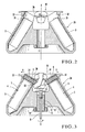
- Fig. 2 is a sectional view taken along the line II - II of Fig. 1
- Fig. 3 is a sectional view showing a state wherein sample tubes are loaded in a rotor of the centrifugal separator.
- members that are the same or identical to those described in the prior art shown in Figs. 7 and 8 described above are denoted by the same reference numerals, and a detailed description thereof will be omitted when necessary.
- the centrifugal separator shown in Figs. 1 to 3 has a rotor 2B having storing holes 3 for storing sample tubes 4 with caps 6.
- the storing holes 3 are inclined with respect to an axis X. Open ends 31 of the storing holes 3 are directed toward the axis X.
- Each storing hole 3 has a contact portion 32, on its open end 31 side, to come into contact with the outer surface of the cap 6 of the sample tube 4.
- the contact portion 32 has a notch 33 at its portion facing the axis X.
- the rotor 2B of a centrifugal separator 1B of this embodiment is characterized in the following respects.
- the four storing holes 3 are arranged at equiangular intervals in the circumferential direction.
- Each cap contact portion 32 is formed with a substantially ring-like shape to surround the cap 6 attached to the opening of the sample tube 4 to project upward from the open end 31 of the corresponding storing hole 3, i.e., from the upper end of the storing hole 3.
- the diameter of a cap storing portion 34 surrounded by the cap contact portion 32 and having a substantially cylindrical shape is slightly larger than a diameter D3 of the cap 6 of the sample tube 4, and the height of the cap storing portion 34 is slightly larger than that of the cap 6.
- the cap 6 of the sample tube 4 is entirely stored in the cap storing portion 34, so that the outer surface of the cap 6 opposes the inner wall of the cap contact portion 32 at a small gap.
- the height of the storing portion 34 suffices as far as it can prevent deformation of the cap 6 in the lateral direction. If the height of the cap storing portion 34 is slightly smaller than that of the cap 6, it poses no problem.
- the notch 33 extending in the direction of the axis X of the rotor 2B is formed in part of each contact portion 32.
- the notch 33 is located toward the axis (rotation center) of the rotor 2B, i.e., on a center hole 11 side, and opposes a recess 2b cylindrically formed in the center of the upper portion of the rotor 2B.
- the cap storing portions 34 are formed on the opposite sides with respect to the axis (rotation center) of the rotor 2B when seen in a plan view, and have fan-like shapes each extending within the range of an angle ⁇ in the circumferential direction where ⁇ > 180°. Because of the notch 33, when the sample tube 4 is stored in the storing hole 3, part of the outer surface of the cap 6 exposes through the notch 33, as will be described later.
- the cap contact portions 32 are formed on the opposite sides with respect to the axis X (rotation center) of the rotor 2B when seen in a plan view, and have fan-like shapes each extending within the range of the angle ⁇ in the circumferential direction where ⁇ > 180°. Accordingly, the outer surface of the cap 6 opposes the cap contact portion 32 except for the rotation center side of the rotor 2B. Even if a centrifugal force acts on the cap 6, the cap 6 comes into contact with the cap contact portion 32, and its deformation is regulated by the cap contact portion 32. Thus, the cap 6 will not deform in the direction of the arrow A or B, i.e., toward the cap contact portion 32.
- the operator puts his or her finger in the notch 33 of the contact portion 32 through the recess 2b of the rotor 2B, and places his finger on the cap 6, to extract the sample tube 4 from the storing hole 3.
- the cap contact portion 32 has the notch 33 which partly exposes the cap 6, the sample tube 4 can be easily extracted from the storing hole 3 of the rotor 2B.
- Figs. 4, 5A, and 5B show the second embodiment of the present invention, in which Fig. 4 is a sectional view showing a state wherein sample tubes are loaded in a rotor, Fig. 5A is a front view showing the outer appearance of a sample tube, and Fig. 5B is a front view showing the outer appearance of an adapter.
- Figs. 4, 5A, and 5B members that are the same or identical to those described in the prior art shown in Fig. 9 and Figs. 10A and 10B described above are denoted by the same reference numerals, and a detailed description thereof will accordingly be omitted when necessary.
- the second embodiment is characterized in the following respects.
- a centrifugal separator having a rotor 2B in which storing holes 3 for storing sample tubes 4A with caps 6A are inclined with respect to an axis X such that open ends 31 of the storing holes 3 are directed toward the axis X
- an adapter is provided in a centrifugal separator having a rotor 2B in which storing holes 3 for storing sample tubes 4A with caps 6A are inclined with respect to an axis X such that open ends 31 of the storing holes 3 are directed toward the axis X.
- the adapter has a holding hole 44 for holding the sample tube 4A.
- a contact portion 43 for coming into contact with the outer surface of the cap 6A of the sample tube 4A is formed on the open end side of the tube holding hole 44.
- a notch 46 is formed in part of the contact portion (cap holding portion) 43.
- an adapter 41 integrally has the substantially cylindrical cap holding portion 43 in its plastic substantially bottomed cylindrical tube holding portion 43, and that the notch 46 vertically extending through the cap holding portion 43 is formed in part of the cap holding portion 43.
- the tube holding portion 42 has the tube holding hole 44 where the tube 5A of the sample tube 4A is to be fitted and held.
- the cap holding portion 43 has a cap holding hole 45 which communicates with the tube holding hole 44 and in which the cap 6A is to be fitted and held.
- the adapter 41 has an outer shape enough to be stored in the storing hole 3.
- a length L3 from the lower end of the cap holding hole 44 of the adapter 41 to the upper end of the cap holding hole 45 is slightly larger than a total length L4 of the sample tube 4A. Accordingly, when the tube 5A of the sample tube 4A is inserted in the tube holding hole 44 of the adapter 41, it fits in the tube holding hole 44 with substantially no gap. Simultaneously, as shown in Fig. 4, the outer surface of the cap 6A opposes the inner wall of the cap holding hole 45 at a small gap such that the cap 6A of the sample tube 4A is entirely stored in the cap holding hole 45 of the adapter 41.
- the adapter 41 which holds the sample tube 4A is stored in the storing hole 3 of the conventional rotor 2A shown in Fig. 9 described above. More specifically, the adapter 41 is stored in the storing hole 3 of the rotor 2A such that the notch 46 of the cap holding portion 43 is directed toward the center hole 11 of the rotor 2A. Then, the adapter 41 fits in the storing hole 3 with substantially no gap, and the cap holding portion 43 of the adapter 41 and the upper end of the tube holding portion 42 project from the storing hole 3.
- the rotor 2A is rotated at a high speed to centrifuge the sample in the sample tube 4A.
- the tube 5A of the sample tube 4A is stored in the storing hole 3 through the tube holding portion 42 of the adapter 41, deformation by the internal pressure of the liquid sample 7 is prevented.
- a centrifugal force in a direction of an arrow A or B in Fig. 4, i.e., in a direction opposite to a direction toward the axis (rotation center) X of the rotor 2A acts on the cap 6A.
- the outer surface of the cap 6A opposes the inner wall of the cap holding portion 43 of the adapter 41 at a small gap.
- the cap 6A comes into contact with the cap holding portion 43, so that deformation of the cap 6A in the direction of the arrow A or B can be regulated.
- Fig. 6 shows an embodiment obtained by combining the first and second embodiments, and reference numerals used in the drawings of the first and second embodiments are employed in this embodiment unchanged.
- an adapter 41 is inserted in the storing hole 3, and a sample tube 4A is stored in the adapter 41.
- an outer portion 43a of a cap holding portion 43 of the adapter 41 is stored in a cap contact portion 32 formed in the rotor 2B.
- the cap holding portion 43 and the cap contact portion 32 have such dimensions that they oppose each other through a predetermined clearance.
- the diameter D3 of the cap 6 is larger than the diameter D1 of the tube 5 at the upper end.
- the diameter D3 and diameter D1 can be set equal to each other. It suffices as far as the diameter D3 is equal to or larger than the diameter D1.
- the diameter D1 of the tube 5 at the upper end is slightly larger than the diameter D2 of the tube 5 at the lower end.
- the diameter D1 and diameter D2 can be set equal to each other. It suffices as far as substantially no gap is formed between the tube 5 and the inner wall of the storing hole 3 when the sample tube 4 is stored in the storing hole 3 of the rotor 2B.
- the adapter 41 is made of a plastic material, it can be made of a metal. Various types of materials can be selectively used to form the adapter 41.
Landscapes
- Health & Medical Sciences (AREA)
- Chemical & Material Sciences (AREA)
- Clinical Laboratory Science (AREA)
- Chemical Kinetics & Catalysis (AREA)
- Analytical Chemistry (AREA)
- General Health & Medical Sciences (AREA)
- Hematology (AREA)
- Centrifugal Separators (AREA)
Abstract
Description
Claims (5)
- In a centrifugal separator comprising a rotor (2B) in which storing holes (3) each for storing a sample tube (4) with a cap (6) are formed to be inclined with respect to an axis (X) such that an open end (31) of each of the storing holes (3) is directed toward the axis (X),
a rotor for the centrifugal separator, characterized in that contact portions (32) each coming into contact with an outer surface of the cap (6) of the sample tube (4) are formed in open end (31) sides of the storing holes (3), and the contact portions (32) respectively have notches (33) at portions thereof which face the axis (X). - A rotor according to claim 1, wherein the storing holes (3) are arranged at equiangular intervals in a circumferential direction, and the contact portions (32) corresponding to the respective storing holes (3) are connected to each other.
- A rotor according to claim 1, wherein the rotor further comprises an adapter (41) having a holding hole (44) for holding a sample tube (4A) with a diameter smaller than that of the sample tube (4), a contact portion (43) coming into contact with an outer surface of a cap (6A) of the sample tube (4A) is formed in an open end side of the holding hole (44), the contact portion (43) has a notch (46) at a portion thereof, and the adapter (41) has an outer diameter which allows the adapter to be stored in the storing hole (3).
- An adapter for the centrifugal separator, characterized by having a holding hole (44) for holding the sample tube (4A), wherein a contact portion (43) coming into contact with an outer surface of the cap (6A) of the sample tube (4A) is formed in an open end side of the holding hole (44), and the contact portion (43) has a notch (46) at a portion thereof.
- An adapter according to claim 4, wherein the contact portion (43) is formed to be higher than the cap (6A) to be attached to the sample tube (4A).
Applications Claiming Priority (2)
| Application Number | Priority Date | Filing Date | Title |
|---|---|---|---|
| JP2002207987A JP3863465B2 (en) | 2002-07-17 | 2002-07-17 | centrifuge |
| JP2002207987 | 2002-07-17 |
Publications (5)
| Publication Number | Publication Date |
|---|---|
| EP1384512A1 true EP1384512A1 (en) | 2004-01-28 |
| EP1384512A2 EP1384512A2 (en) | 2004-01-28 |
| EP1384512A3 EP1384512A3 (en) | 2004-05-06 |
| EP1384512A8 EP1384512A8 (en) | 2004-05-26 |
| EP1384512B1 EP1384512B1 (en) | 2016-09-28 |
Family
ID=29997167
Family Applications (1)
| Application Number | Title | Priority Date | Filing Date |
|---|---|---|---|
| EP03016000.6A Expired - Lifetime EP1384512B1 (en) | 2002-07-17 | 2003-07-14 | Rotor for centrifugal separator and adapter for centrifugal separator |
Country Status (3)
| Country | Link |
|---|---|
| US (1) | US7004898B2 (en) |
| EP (1) | EP1384512B1 (en) |
| JP (1) | JP3863465B2 (en) |
Cited By (1)
| Publication number | Priority date | Publication date | Assignee | Title |
|---|---|---|---|---|
| US7004898B2 (en) * | 2002-07-17 | 2006-02-28 | Kabushiki Kaisha Kubota Seisakusho | Rotor for a centrifugal separator |
Families Citing this family (8)
| Publication number | Priority date | Publication date | Assignee | Title |
|---|---|---|---|---|
| JP4465976B2 (en) * | 2002-04-26 | 2010-05-26 | 日立工機株式会社 | Culture centrifuge tube for centrifuge |
| WO2007012056A2 (en) * | 2005-07-19 | 2007-01-25 | Hansen Thomas C | Tangential manufacturing system |
| JP5871127B2 (en) * | 2012-02-03 | 2016-03-01 | 三菱レイヨン株式会社 | Jig for storing cylindrical casing |
| CN209452049U (en) | 2016-05-31 | 2019-10-01 | 工机控股株式会社 | Rotor and centrifuge using same |
| JP1619045S (en) * | 2018-03-09 | 2018-11-26 | ||
| USD877929S1 (en) * | 2018-03-19 | 2020-03-10 | Fiberlite Centrifuge, Llc | Centrifuge rotor |
| CN112206930B (en) * | 2020-09-10 | 2022-03-08 | 四川行之智汇知识产权运营有限公司 | Centrifugal blood separator |
| CN114804564A (en) * | 2021-01-29 | 2022-07-29 | 阿法拉伐股份有限公司 | Method for removing solids from biogas residues obtained from biogas plants |
Citations (5)
| Publication number | Priority date | Publication date | Assignee | Title |
|---|---|---|---|---|
| US3133882A (en) * | 1961-07-21 | 1964-05-19 | Internat Equipment Company | Centrifuges with retainers, retainers, and bottle stoppers for use therewith |
| US3998383A (en) * | 1975-07-16 | 1976-12-21 | E. I. Du Pont De Nemours And Company | Gradient separation apparatus |
| US4832678A (en) * | 1987-12-03 | 1989-05-23 | E. I. Du Pont De Nemours And Company | Adapter for a centrifuge tube and a removal tool therefor |
| US5354254A (en) * | 1993-04-15 | 1994-10-11 | Separation Technology, Inc. | Centrifuge rotor head with tube neck support |
| EP0626206A2 (en) * | 1993-05-27 | 1994-11-30 | E.I. Du Pont De Nemours And Company | Adapter for centrifuge tube |
Family Cites Families (17)
| Publication number | Priority date | Publication date | Assignee | Title |
|---|---|---|---|---|
| US3366320A (en) * | 1965-07-21 | 1968-01-30 | Atomic Energy Commission Usa | Centrifuge sample holder |
| US4076170A (en) | 1977-04-18 | 1978-02-28 | Beckman Instruments, Inc. | Tube cap assembly for preparative centrifuge rotors |
| US4301963A (en) | 1978-06-05 | 1981-11-24 | Beckman Instruments, Inc. | Integral one piece centrifuge tube |
| US4304356A (en) | 1980-02-19 | 1981-12-08 | Beckman Instruments, Inc. | Supporting cap for sealed centrifuge tube |
| JPS5822254B2 (en) * | 1981-07-03 | 1983-05-07 | 株式会社 久保田製作所 | Centrifuge rotor |
| US4412830A (en) | 1982-06-24 | 1983-11-01 | Beckman Instruments, Inc. | Cover for centrifuge rotor |
| JPH0634946B2 (en) * | 1985-03-04 | 1994-05-11 | 日立化成工業株式会社 | Rotor for centrifuge |
| JPH01293151A (en) * | 1988-05-20 | 1989-11-27 | Hitachi Koki Co Ltd | Rotor for centrifugal separator |
| US5382220A (en) * | 1989-11-07 | 1995-01-17 | E. I. Du Pont De Nemours And Company | Centrifuge tube adapter |
| JPH0515955U (en) | 1991-08-14 | 1993-03-02 | 川澄化学工業株式会社 | Medical needle |
| US5310527A (en) * | 1992-12-14 | 1994-05-10 | E. I. Du Pont De Nemours And Company | Tube for use in a pelleting centrifuge rotor |
| JP3326764B2 (en) * | 1995-05-19 | 2002-09-24 | 株式会社久保田製作所 | Angle rotor for centrifuge |
| FI101610B (en) * | 1995-11-22 | 1998-07-31 | Clids Oy | The sample sensor |
| US5728038A (en) * | 1997-04-25 | 1998-03-17 | Beckman Instruments, Inc. | Centrifuge rotor having structural stress relief |
| JP4465976B2 (en) | 2002-04-26 | 2010-05-26 | 日立工機株式会社 | Culture centrifuge tube for centrifuge |
| JP3863465B2 (en) * | 2002-07-17 | 2006-12-27 | 株式会社久保田製作所 | centrifuge |
| US7118522B2 (en) * | 2003-04-15 | 2006-10-10 | Beckman Coulter, Inc. | Centrifuge adapter |
-
2002
- 2002-07-17 JP JP2002207987A patent/JP3863465B2/en not_active Expired - Lifetime
-
2003
- 2003-07-14 EP EP03016000.6A patent/EP1384512B1/en not_active Expired - Lifetime
- 2003-07-16 US US10/620,889 patent/US7004898B2/en not_active Expired - Lifetime
Patent Citations (5)
| Publication number | Priority date | Publication date | Assignee | Title |
|---|---|---|---|---|
| US3133882A (en) * | 1961-07-21 | 1964-05-19 | Internat Equipment Company | Centrifuges with retainers, retainers, and bottle stoppers for use therewith |
| US3998383A (en) * | 1975-07-16 | 1976-12-21 | E. I. Du Pont De Nemours And Company | Gradient separation apparatus |
| US4832678A (en) * | 1987-12-03 | 1989-05-23 | E. I. Du Pont De Nemours And Company | Adapter for a centrifuge tube and a removal tool therefor |
| US5354254A (en) * | 1993-04-15 | 1994-10-11 | Separation Technology, Inc. | Centrifuge rotor head with tube neck support |
| EP0626206A2 (en) * | 1993-05-27 | 1994-11-30 | E.I. Du Pont De Nemours And Company | Adapter for centrifuge tube |
Cited By (1)
| Publication number | Priority date | Publication date | Assignee | Title |
|---|---|---|---|---|
| US7004898B2 (en) * | 2002-07-17 | 2006-02-28 | Kabushiki Kaisha Kubota Seisakusho | Rotor for a centrifugal separator |
Also Published As
| Publication number | Publication date |
|---|---|
| EP1384512A3 (en) | 2004-05-06 |
| JP2004049970A (en) | 2004-02-19 |
| JP3863465B2 (en) | 2006-12-27 |
| EP1384512B1 (en) | 2016-09-28 |
| US20050101467A1 (en) | 2005-05-12 |
| EP1384512A8 (en) | 2004-05-26 |
| US7004898B2 (en) | 2006-02-28 |
Similar Documents
| Publication | Publication Date | Title |
|---|---|---|
| US7004898B2 (en) | Rotor for a centrifugal separator | |
| US10682616B2 (en) | Centrifuge with exchangeable rotors | |
| EP2399675A2 (en) | Centrifuge sample container and centrifuge | |
| US4832678A (en) | Adapter for a centrifuge tube and a removal tool therefor | |
| JP2550636Y2 (en) | Sealing device for centrifuge tubes | |
| JP4329207B2 (en) | Centrifuge rotor and centrifuge | |
| EP0709139B1 (en) | Centrifuge rotor | |
| US6190300B1 (en) | Centrifuge rotor adapted for use with centrifuge tube strips | |
| EP0642389B1 (en) | Centrifuge | |
| EP0368173A2 (en) | Cavity sealing system for a centrifuge rotor | |
| US20030203800A1 (en) | Culture tube and angle rotor receiving the tube in centrifuge | |
| WO1997009119A1 (en) | Tube adapter for centrifuge shell type rotor | |
| US4102490A (en) | Data ring for vertical tube rotor | |
| CN113318867A (en) | Centrifugal machine is with getting rid of flat rotor | |
| US5840005A (en) | Centrifuge with inertial mass relief | |
| US5591114A (en) | Swinging bucket centrifuge rotor | |
| JP2007152209A (en) | Centrifuge rotor and centrifuge | |
| JPH07507723A (en) | Centrifuge tube with snap plug | |
| JP3150983B2 (en) | Bucket used for swing bucket type centrifuge rotor | |
| JP4279545B2 (en) | Crushing and centrifugation methods | |
| JP2003305381A (en) | Centrifugal rotor | |
| US6866622B2 (en) | Centrifugal rotor having buckets swingably supported on a hinge shaft | |
| JPH0135248Y2 (en) | ||
| CN223405135U (en) | Angle rotors and centrifuges | |
| JPH09262503A (en) | Centrifuge rotor |
Legal Events
| Date | Code | Title | Description |
|---|---|---|---|
| PUAI | Public reference made under article 153(3) epc to a published international application that has entered the european phase |
Free format text: ORIGINAL CODE: 0009012 |
|
| AK | Designated contracting states |
Kind code of ref document: A1 Designated state(s): AT BE BG CH CY CZ DE DK EE ES FI FR GB GR HU IE IT LI LU MC NL PT RO SE SI SK TR |
|
| AX | Request for extension of the european patent |
Extension state: AL LT LV MK |
|
| PUAB | Information related to the publication of an a document modified or deleted |
Free format text: ORIGINAL CODE: 0009199EPPU |
|
| PUAF | Information related to the publication of a search report (a3 document) modified or deleted |
Free format text: ORIGINAL CODE: 0009199SEPU |
|
| PUAL | Search report despatched |
Free format text: ORIGINAL CODE: 0009013 |
|
| PUAF | Information related to the publication of a search report (a3 document) modified or deleted |
Free format text: ORIGINAL CODE: 0009199SEPU |
|
| D17D | Deferred search report published (deleted) | ||
| RA1 | Application published (corrected) |
Date of ref document: 20040128 Kind code of ref document: A2 |
|
| AK | Designated contracting states |
Kind code of ref document: A3 Designated state(s): AT BE BG CH CY CZ DE DK EE ES FI FR GB GR HU IE IT LI LU MC NL PT RO SE SI SK TR |
|
| AX | Request for extension of the european patent |
Extension state: AL LT LV MK |
|
| D17D | Deferred search report published (deleted) | ||
| PUAL | Search report despatched |
Free format text: ORIGINAL CODE: 0009013 |
|
| AK | Designated contracting states |
Kind code of ref document: A3 Designated state(s): AT BE BG CH CY CZ DE DK EE ES FI FR GB GR HU IE IT LI LU MC NL PT RO SE SI SK TR |
|
| AX | Request for extension of the european patent |
Extension state: AL LT LV MK |
|
| 17P | Request for examination filed |
Effective date: 20040709 |
|
| AKX | Designation fees paid |
Designated state(s): DE FR GB IT |
|
| RBV | Designated contracting states (corrected) |
Designated state(s): DE FR GB IT |
|
| 17Q | First examination report despatched |
Effective date: 20070430 |
|
| GRAP | Despatch of communication of intention to grant a patent |
Free format text: ORIGINAL CODE: EPIDOSNIGR1 |
|
| INTG | Intention to grant announced |
Effective date: 20160414 |
|
| GRAS | Grant fee paid |
Free format text: ORIGINAL CODE: EPIDOSNIGR3 |
|
| GRAA | (expected) grant |
Free format text: ORIGINAL CODE: 0009210 |
|
| AK | Designated contracting states |
Kind code of ref document: B1 Designated state(s): DE FR GB IT |
|
| REG | Reference to a national code |
Ref country code: GB Ref legal event code: FG4D |
|
| REG | Reference to a national code |
Ref country code: DE Ref legal event code: R096 Ref document number: 60349437 Country of ref document: DE |
|
| REG | Reference to a national code |
Ref country code: DE Ref legal event code: R097 Ref document number: 60349437 Country of ref document: DE |
|
| PG25 | Lapsed in a contracting state [announced via postgrant information from national office to epo] |
Ref country code: IT Free format text: LAPSE BECAUSE OF FAILURE TO SUBMIT A TRANSLATION OF THE DESCRIPTION OR TO PAY THE FEE WITHIN THE PRESCRIBED TIME-LIMIT Effective date: 20160928 |
|
| REG | Reference to a national code |
Ref country code: FR Ref legal event code: PLFP Year of fee payment: 15 |
|
| PLBE | No opposition filed within time limit |
Free format text: ORIGINAL CODE: 0009261 |
|
| STAA | Information on the status of an ep patent application or granted ep patent |
Free format text: STATUS: NO OPPOSITION FILED WITHIN TIME LIMIT |
|
| 26N | No opposition filed |
Effective date: 20170629 |
|
| REG | Reference to a national code |
Ref country code: FR Ref legal event code: PLFP Year of fee payment: 16 |
|
| PGFP | Annual fee paid to national office [announced via postgrant information from national office to epo] |
Ref country code: GB Payment date: 20200615 Year of fee payment: 18 |
|
| PGFP | Annual fee paid to national office [announced via postgrant information from national office to epo] |
Ref country code: FR Payment date: 20200731 Year of fee payment: 18 Ref country code: DE Payment date: 20200730 Year of fee payment: 18 |
|
| REG | Reference to a national code |
Ref country code: DE Ref legal event code: R119 Ref document number: 60349437 Country of ref document: DE |
|
| GBPC | Gb: european patent ceased through non-payment of renewal fee |
Effective date: 20210714 |
|
| PG25 | Lapsed in a contracting state [announced via postgrant information from national office to epo] |
Ref country code: GB Free format text: LAPSE BECAUSE OF NON-PAYMENT OF DUE FEES Effective date: 20210714 Ref country code: DE Free format text: LAPSE BECAUSE OF NON-PAYMENT OF DUE FEES Effective date: 20220201 |
|
| PG25 | Lapsed in a contracting state [announced via postgrant information from national office to epo] |
Ref country code: FR Free format text: LAPSE BECAUSE OF NON-PAYMENT OF DUE FEES Effective date: 20210731 |