EP1384283B1 - Hybrid fiber/coax system mit optischem kombinieren für den rückwärtsweg unter verwendung eines optischen kommutators - Google Patents
Hybrid fiber/coax system mit optischem kombinieren für den rückwärtsweg unter verwendung eines optischen kommutators Download PDFInfo
- Publication number
- EP1384283B1 EP1384283B1 EP02736588A EP02736588A EP1384283B1 EP 1384283 B1 EP1384283 B1 EP 1384283B1 EP 02736588 A EP02736588 A EP 02736588A EP 02736588 A EP02736588 A EP 02736588A EP 1384283 B1 EP1384283 B1 EP 1384283B1
- Authority
- EP
- European Patent Office
- Prior art keywords
- optical
- signals
- commutator
- transmitters
- combined
- Prior art date
- Legal status (The legal status is an assumption and is not a legal conclusion. Google has not performed a legal analysis and makes no representation as to the accuracy of the status listed.)
- Expired - Lifetime
Links
- 230000003287 optical effect Effects 0.000 title claims abstract description 161
- 239000000835 fiber Substances 0.000 title claims description 28
- 238000004891 communication Methods 0.000 claims description 23
- 239000013307 optical fiber Substances 0.000 abstract description 4
- 238000010586 diagram Methods 0.000 description 11
- 238000005070 sampling Methods 0.000 description 6
- 238000011144 upstream manufacturing Methods 0.000 description 4
- 230000002452 interceptive effect Effects 0.000 description 2
- 230000005540 biological transmission Effects 0.000 description 1
- 230000003247 decreasing effect Effects 0.000 description 1
- 230000000694 effects Effects 0.000 description 1
- 238000000034 method Methods 0.000 description 1
Images



Classifications
-
- H—ELECTRICITY
- H04—ELECTRIC COMMUNICATION TECHNIQUE
- H04J—MULTIPLEX COMMUNICATION
- H04J14/00—Optical multiplex systems
- H04J14/02—Wavelength-division multiplex systems
- H04J14/0278—WDM optical network architectures
- H04J14/0282—WDM tree architectures
-
- H—ELECTRICITY
- H04—ELECTRIC COMMUNICATION TECHNIQUE
- H04B—TRANSMISSION
- H04B10/00—Transmission systems employing electromagnetic waves other than radio-waves, e.g. infrared, visible or ultraviolet light, or employing corpuscular radiation, e.g. quantum communication
- H04B10/50—Transmitters
- H04B10/501—Structural aspects
- H04B10/506—Multiwavelength transmitters
-
- H—ELECTRICITY
- H04—ELECTRIC COMMUNICATION TECHNIQUE
- H04J—MULTIPLEX COMMUNICATION
- H04J14/00—Optical multiplex systems
- H04J14/02—Wavelength-division multiplex systems
- H04J14/0227—Operation, administration, maintenance or provisioning [OAMP] of WDM networks, e.g. media access, routing or wavelength allocation
- H04J14/0241—Wavelength allocation for communications one-to-one, e.g. unicasting wavelengths
- H04J14/0242—Wavelength allocation for communications one-to-one, e.g. unicasting wavelengths in WDM-PON
- H04J14/0249—Wavelength allocation for communications one-to-one, e.g. unicasting wavelengths in WDM-PON for upstream transmission, e.g. ONU-to-OLT or ONU-to-ONU
-
- H—ELECTRICITY
- H04—ELECTRIC COMMUNICATION TECHNIQUE
- H04J—MULTIPLEX COMMUNICATION
- H04J14/00—Optical multiplex systems
- H04J14/02—Wavelength-division multiplex systems
- H04J14/0226—Fixed carrier allocation, e.g. according to service
Definitions
- This invention relates generally to broadband communications systems, such as hybrid/fiber coaxial (HFC) systems, and more specifically to an apparatus for combining optical signals from a plurality of optical transmitters.
- HFC hybrid/fiber coaxial
- FIG. 1 is a block diagram illustrating an example of one branch of a conventional broadband communications system, such as a two-way hybrid/fiber coaxial (HFC) system, that carries optical and electrical signals.
- a conventional broadband communications system such as a two-way hybrid/fiber coaxial (HFC) system
- the communications system 100 includes headend equipment 105 for generating forward signals (e.g., voice, video, or data signals) that are typically transmitted as optical signals in the forward, or downstream, direction along a first communication medium, such as a fiber optic cable 110.
- RF radio frequency
- the electrical signals are further transmitted along a second communication medium, such as coaxial cable 120, and are amplified, as necessary, by one or more distribution amplifiers 125 positioned along the communication medium.
- RF radio frequency
- Passive splitter/combiner devices 130 may also be added to the network 100 to split the electrical signals in the forward path, thereby delivering signals to separate portions of the network 100.
- Taps 135 then further split the forward signals for provision to subscriber equipment 140, such as set-top terminals, computers, telephone handsets, modems, and televisions.
- subscriber equipment 140 such as set-top terminals, computers, telephone handsets, modems, and televisions. It will be appreciated that only one branch connecting the headend equipment 105 with the plurality of subscriber equipment 140 is shown for simplicity; however, there are typically several different fiber links connecting the headend equipment 105 with several additional nodes 115, amplifiers 125, and subscriber equipment 140.
- the subscriber equipment 140 can also generate reverse signals that are transmitted upstream through the reverse path to the headend equipment 105.
- Such reverse signals may be combined via the splitter/combiner devices 130 along with other reverse signals and then amplified by any one or more of the distribution amplifiers 125.
- the signals are then converted to optical signals by the optical node 115 before being provided to the headend equipment 105. It will be appreciated that in the electrical, or coaxial cable, portion of the network 100, the forward and reverse path signals are carried on the same coaxial cable 120.
- Headend equipment 205 generates and transmits optical signals via optical transmitters 210a-n downstream through their respective fiber links 215a-n. It will be appreciated that there are a plurality of optical transmitters 210a-n transmitting optical signals to a plurality of nodes 220a-n, where each node 220 services a different portion of the system depending upon the system design. Within the nodes 220a-n, an optical receiver 230a-n converts the optical signals to electrical signals for delivery through the coaxial portion of the network. Before transmission, a diplex filter 235a-n isolates the forward electrical signals from the reverse electrical signals and provides the electrical signals to coaxial cable 240a-n for delivery to a plurality of subscriber equipment 245-n.
- electrical signals emanating from the plurality of subscriber equipment 245a-n are transmitted upstream via the coaxial cable 240a-n to the respective node 220a-n.
- the diplex filter 235a-n isolates the reverse electrical signals from the forward electrical signals and provides the reverse signals to an optical transmitter 250a-n for converting the electrical signals to optical signals for delivery through the fiber portion of the network.
- the optical signals are then transmitted further upstream via a reverse optical fiber 255a-n to an optical receiver 260a-n that may also be located within the headend.
- the optical receiver 260a-n converts the optical signals to electrical signals.
- Each optical receiver 260a-n then transmits the electrical signals to a passive splitter/combiner 265 for combining the electrical signals in the conventional electrical manner.
- the electrical signals is the same as if the electrical signals from subscriber equipment was combined and carried back to the headend via analog means. Additional equipment within the headend then receives the combined electrical signal and, based on the bandwidth allocation scheme, routes portions of the signal to the correct equipment for further processing.
- an operator can accomplish this by decreasing the number of subscriber homes that a node 220, or path, services. For example, an operator can reduce an existing path that includes 2000 subscriber homes per node to 500 subscriber homes per node, and add three additional paths each including a node to service that portion of the network. It can easily be understood that increasing the size or optimizing the network requires a significant amount of equipment, fiber, and labor.
- optical signals may be combined via a passive optical combiner, similar to a passive electrical combiner, as long as the optical transmitters, optical combiner, and optical receiver are restricted to a controlled environment.
- a passive optical combiner similar to a passive electrical combiner, as long as the optical transmitters, optical combiner, and optical receiver are restricted to a controlled environment.
- a controlled environment is difficult to achieve.
- a broadband communications system such as the system shown in FIG. 1
- many components are exposed to the environment, such as varying regions and temperatures. Consequently, optical transmitters may begin transmitting optical signals at a particular wavelength, but due to heat that is imposed upon the transmitter, for example, the afternoon sun, the wavelength drifts.
- the intermodulation distortion that is produced in the optical receiver will then obscure the desired signals.
- devices and networks that are capable of transmitting and combining reverse optical signals, similar to the combining of reverse electrical signals, without having to employ optical transmitters that transmit signals at differing wavelengths. More specifically, the devices and networks need to be able to combine optical signals that may have similar wavelengths, or allow for wavelength drift, while still allowing the optical receiver to distinguish between the different optical signals. Additionally, the operator would like to use existing equipment, such as optical transmitters, that may already be placed within the network.
- the European patent application EP 0 593 206 A1 discloses an optical commutator for combining a plurality of optical signals, comprising: a plurality of input ports, each of the input ports receiving one of the plurality of optical signals, the bandwidth of the plurality of optical signals being less than or equal to a predetermined bandwidth; an output port for providing a combined optical signal including the plurality of optical signals; and switching means for sequentially connecting each of the plurality of input ports to the output port, where each of the plurality of input ports is connected to the output port at a frequency greater than twice the predetermined bandwidth.
- the present invention will be described more fully hereinafter with reference to the accompanying drawings in which like numerals represent like elements throughout the several figures, and in which an exemplary embodiment of the invention is shown.
- This invention may, however, be embodied in many different forms and should not be construed as limited to the embodiment set forth herein; rather, the embodiment is provided so that this disclosure will be thorough and complete, and will fully convey the scope of the invention to those skilled in the art.
- the preferred embodiment set forth herein refers to an optical commutator, or optical combiner, that is in a broadband communications system that combines reverse optical signals from a plurality of optical transmitters.
- other embodiments of the present invention may use the optical commutator of the present invention in the forward path or to combine digital optical signals. The present invention is described more fully hereinbelow.
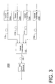
- a fiber communications path 300 in accordance with the present invention that includes an optical commutator 310 for combining optical signals from a plurality of optical transmitters 305a-n.
- the optical transmitters 305a-n may be placed within a node, such as node 220a-n ( FIG. 2 ), or configured as stand-alone units.
- optical signals emanating from the plurality of transmitters 305a-n are combined through an optical commutator 310, which is coupled to the transmitters 305a-n via fibers 315a-n.
- the combined optical signal is then provided, via a single optical fiber 318, to an optical receiver 320 that is located further upstream or within a headend (not shown).
- the optical receiver 320 converts the combined optical signal to a combined electrical signal.
- the combined electrical signal is then routed in the conventional electrical manner to additional headend equipment for further processing.
- the passive splitter/combiner device 265 combines the electrical signals from each of the optical receivers 260a-n.
- a splitter/combiner device is not required in the present invention since the optical receiver 320 ( FIG. 3 ) provides a similar combined electrical signal at its output port.
- the present invention By employing the present invention to combine the optical signals, a system operator is able to upgrade the network in a couple of ways. First, the operator may need to add an additional node to service additional subscribers; and second, the operator may need to add a reverse path if one doesn't currently exist to offer interactive services.
- the received optical signals may be transmitted without having to use separate fiber optic cable linking the optical transmitters to separate optical receivers. In this manner, the present invention substantially reduces the amount of previously required optical receivers and fiber that was required in conventional systems. It will be appreciated that in accordance with the present invention the number of optical transmitters that inputs signals to the commutator 310 is not limited to four as shown in FIG.
- the lengths of the fibers 315a-n may also vary and do not need to be of equal distance.
- the optical transmitters 305a-n and the optical receiver 320 are, advantageously, conventional equipment, which is equipment used in the system shown in FIG. 2 .
- optical signals can be easily combined using conventional electrical techniques in the coaxial portion of the HFC network.
- optical signals cannot be combined within the fiber portion of the HFC system due to the negative effects if two or more signals arrive at the optical receiver that each possesses the same or similar wavelengths. This occurrence is fairly typical within an HFC system, such as the systems shown in FIGs. 1 and 2 . Consequently, if an optical receiver within a conventional network receives at least two optical signals that each has the same or similar wavelength, the output of the optical receiver will contain only noise resulting from intermodulation distortion between the similar optical signals.
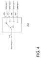
- FIG. 4 is a block diagram of the optical commutator 310 in accordance with the present invention that is suitable for combining optical signals in the communications fiber path 300 of FIG. 3 .
- the commutator 310 samples each of the optical input ports 405a-d, via switch 410, at a specified switching time depending upon the frequency band of the transmitted data signals and the number of input ports.
- the switch is essentially the optical equivalent to an electrical rotary switch. Alternatively, the switch may be a high-speed optical switch.
- the combined, or sampled, output signal is then provided to output port 415.
- the switch 410 samples each of the input ports 405 at specified time intervals depending upon the number of input ports 405 and the frequency band at which the data is routed throughout the communications path to sample the received signals adequately.
- Nyquist theory states an analog signal must be sampled at a frequency that is greater than twice the maximum signal bandwidth in order to ensure that all information can be extracted and the inherent aliasing due to the sampling will not corrupt the original signal. For example, if the communications path in an HFC system, routes data throughout the system in the frequency band from 5 Mega Hertz (MHz) to 42 MHz, the maximum signal bandwidth is 37 MHz. Per Nyquist, two times 37 results in a 74 MHz.
- 74 MHz may then be increased to 100 MHz to ensure adequate sampling of the signal.
- a sampling frequency of 100 MHz corresponds to one sample every 10 nano seconds (ns).
- the number of input ports of the optical commutator is divided into the switching time to determine the amount of time that the switch 410 switches between each of the input ports to ensure adequate sampling of each signal.
- the cycle time for sampling the four input ports 405a-d is 10 ns, which is the 100 MHz rate.
- FIG. 5 is an example illustrating timing diagrams of four input optical signals from the optical transmitters 405a-d and an output signal of the optical commutator 410 in accordance with the present invention.
- the first four timing diagrams 505a-d represent analog optical signals that are provided to the input ports 405a-d ( FIG. 4 ) of the optical commutator 310 ( FIG. 4 ).
- the last timing diagram 510 represents the output of the optical commutator, which combines the input signals.
- the combined output signal samples each input signal for 2.5 ns and combines, or sums, the four input signals into the combined output signal.
- the optical receiver 320 receives the combined output signal and converts it to a combined electrical signal.
- this combined electrical signal is essentially the same signal as the previously combined electrical signal of FIG. 2 , which uses the passive combiner 265 to combine the electrical signals from several optical receivers 260a-n.
- a system operator may use several optical receivers 320 ( FIG. 3 ) within the network. In this case, the operator may need to use the passive splitter/combiner to combine the several combined electrical signals from each of the optical receivers. In this manner, the passive splitter/combiner combines all combined electrical signals and supplies the signal to additional headend equipment.
- the preferred embodiment is directed to combining analog optical signals in the reverse path of a broadband communications system; however, it will be appreciated that if an optical commutator can sample sufficiently fast, digital optical signals may also combined using the optical commutator 310. For example, if digital optical signals have a data rate throughout the network of 1 Giga bits per second (Gb/s), the optical commutator would be required to sample at a rate much faster than 1 Gb/s.
- Gb/s Giga bits per second
- an optical commutator 310 is used to combine optical signals from a plurality of optical transmitters 305a-n in the fiber communications path 300.
- this allows an operator to add the optical commutator 310 to the network in accordance with the present invention and continue using their existing optical transmitters 305a-n.
- separate fiber links 315a-n will link the commutator 310 with the plurality of optical transmitters 305a-n.
- the commutator 310 then sends the combined optical signal to one optical receiver 320 over a single fiber cable 318.
- the present invention therefore, allows a substantial decrease in the requirements for optical fiber and the number of optical receivers 320 while allowing the operator an efficient delivery system for combining optical signals.
Landscapes
- Engineering & Computer Science (AREA)
- Computer Networks & Wireless Communication (AREA)
- Signal Processing (AREA)
- Physics & Mathematics (AREA)
- Electromagnetism (AREA)
- Optical Communication System (AREA)
- Use Of Switch Circuits For Exchanges And Methods Of Control Of Multiplex Exchanges (AREA)
Claims (3)
- Zweiweg-Hybrid-Glasfaser-Coax(HFC)-Kommunikationssystem mit einem Vorwärtsweg und einem Rückwärtsweg zum Übertragen von Signalen, wobei der Rückwärtsweg mehrere optische Sender (305a - 305n) jeweils zum Senden von analogen optischen Signalen in einer vorgegebenen Bandbreite über ein Glasfaserkabel (315a - 315n) aufweist,
dadurch gekennzeichnet, dass der Rückwärtsweg weiterhin einen optischen Kommutator (310) aufweist, der über das Glasfaserkabel mit jedem der mehreren optischen Sender verbunden ist, um die analogen optischen Signale zu einem kombinierten analogen optischen Signal zu vereinen, wobei der optische Kommutator (310) Folgendes aufweist:mehrere Eingangsanschlüsse (405a - 405d) zum Empfangen der analogen optischen Signale von den mehreren optischen Sendern;einen Ausgangsanschluss (415) zum Bereitstellen des kombinierten analogen optischen Signals, das eine Kombination der analogen optischen Signale von den Eingangsanschlüssen ist; undeinen Schalter (410) zum nacheinander Verbinden jedes der mehreren Eingangsanschlüsse mit dem Ausgangsanschluss, wobei immer nur ein Eingangsanschluss auf einmal mit dem Ausgangsanschluss verbunden wird, um die analogen optischen Signale zu dem kombinierten analogen optischen Signal zu vereinen, wobei jeder der Eingangsanschlüsse mit einer Frequenz, die größer als das Zweifache der vorgegebenen Bandbreite ist, nach dem Nyquist-Kriterium mit dem Ausgangsanschluss verbunden wird,wobei das Kommunikationssystem weiterhin eine Kopfstelleneinrichtung zum Empfangen des ausgegebenen kombinierten analogen optischen Signals von dem optischen Empfangskommutator (310) zum weiteren Verarbeiten des Ausgangssignals aufweist. - Kommunikationssystem nach Anspruch 1, dadurch gekennzeichnet, dass der Schalter ein optischer Hochgeschwindigkeitsschalter ist.
- Kommunikationssystem nach Anspruch 1, dadurch gekennzeichnet, dass die vorgegebene Bandbreite in dem Rückwärtsweg 5 MHz bis 40 MHz beträgt.
Applications Claiming Priority (3)
| Application Number | Priority Date | Filing Date | Title |
|---|---|---|---|
| US840766 | 1992-02-24 | ||
| US09/840,766 US6570693B2 (en) | 2001-04-23 | 2001-04-23 | Reverse path optical combining using an optical commutator |
| PCT/US2002/012367 WO2002093686A1 (en) | 2001-04-23 | 2002-04-19 | Reverse path optical combining using an optical commutator |
Publications (3)
| Publication Number | Publication Date |
|---|---|
| EP1384283A1 EP1384283A1 (de) | 2004-01-28 |
| EP1384283A4 EP1384283A4 (de) | 2006-07-05 |
| EP1384283B1 true EP1384283B1 (de) | 2008-10-29 |
Family
ID=25283170
Family Applications (1)
| Application Number | Title | Priority Date | Filing Date |
|---|---|---|---|
| EP02736588A Expired - Lifetime EP1384283B1 (de) | 2001-04-23 | 2002-04-19 | Hybrid fiber/coax system mit optischem kombinieren für den rückwärtsweg unter verwendung eines optischen kommutators |
Country Status (6)
| Country | Link |
|---|---|
| US (1) | US6570693B2 (de) |
| EP (1) | EP1384283B1 (de) |
| BR (1) | BRPI0208582B1 (de) |
| DE (2) | DE60229628D1 (de) |
| ES (1) | ES2209682T1 (de) |
| WO (1) | WO2002093686A1 (de) |
Families Citing this family (1)
| Publication number | Priority date | Publication date | Assignee | Title |
|---|---|---|---|---|
| US20080220731A1 (en) * | 2007-03-08 | 2008-09-11 | West Lamar E | Reverse path optical link using frequency modulation |
Family Cites Families (5)
| Publication number | Priority date | Publication date | Assignee | Title |
|---|---|---|---|---|
| US5329393A (en) * | 1992-10-15 | 1994-07-12 | At&T Bell Laboratories | Optical Nyquist rate multiplexer and demultiplexer |
| US5347288A (en) | 1993-05-26 | 1994-09-13 | Westinghouse Electric Corporation | Optical commutator |
| US5325102A (en) | 1993-06-04 | 1994-06-28 | Westinghouse Electric Corporation | Receiver system employing an optical commutator |
| US6204947B1 (en) | 1998-03-02 | 2001-03-20 | Derrick J Page | Multi-stage optical commutator |
| US6002365A (en) | 1998-05-26 | 1999-12-14 | Page; Derrick J. | Antenna beam steering using an optical commutator to delay the local oscillator sigal |
-
2001
- 2001-04-23 US US09/840,766 patent/US6570693B2/en not_active Expired - Lifetime
-
2002
- 2002-04-19 WO PCT/US2002/012367 patent/WO2002093686A1/en not_active Ceased
- 2002-04-19 EP EP02736588A patent/EP1384283B1/de not_active Expired - Lifetime
- 2002-04-19 DE DE60229628T patent/DE60229628D1/de not_active Expired - Lifetime
- 2002-04-19 DE DE0001384283T patent/DE02736588T1/de active Pending
- 2002-04-19 ES ES02736588T patent/ES2209682T1/es active Pending
- 2002-04-19 BR BRPI0208582A patent/BRPI0208582B1/pt not_active IP Right Cessation
Also Published As
| Publication number | Publication date |
|---|---|
| DE60229628D1 (de) | 2008-12-11 |
| DE02736588T1 (de) | 2004-07-15 |
| EP1384283A4 (de) | 2006-07-05 |
| US20020154368A1 (en) | 2002-10-24 |
| BR0208582A (pt) | 2004-04-20 |
| WO2002093686A1 (en) | 2002-11-21 |
| ES2209682T1 (es) | 2004-07-01 |
| US6570693B2 (en) | 2003-05-27 |
| EP1384283A1 (de) | 2004-01-28 |
| BRPI0208582B1 (pt) | 2016-09-06 |
Similar Documents
| Publication | Publication Date | Title |
|---|---|---|
| US6356369B1 (en) | Digital optical transmitter for processing externally generated information in the reverse path | |
| US6523177B1 (en) | Cable television system with digital reverse path architecture | |
| US7058966B2 (en) | Optical communication system for transmitting RF signals downstream and bidirectional telephony signals which also include RF control signals upstream | |
| US5864748A (en) | Hybrid fiber-coax system having at least one digital fiber node and increased upstream and downstream bandwidth | |
| US7016308B1 (en) | Digital return path for hybrid fiber/coax network | |
| US6775433B2 (en) | Deep fiber network with high speed data and video on demand | |
| US6509994B2 (en) | Burst-mode analog transmitter | |
| US6462851B1 (en) | Network and method for transmitting reverse analog signals by sub-sampling the digital reverse bandwidth | |
| US7614074B2 (en) | Burst-mode digital transmitter | |
| US20030023983A1 (en) | Cable television system with digital reverse path architecture | |
| EP1235434B1 (de) | Zweiwegnetzwerk zur Verteilung von Kabel-TV-Signalen an Endpunkte mittels optischer Fasern | |
| US20030063847A1 (en) | Deep fiber network architecture | |
| US6570693B2 (en) | Reverse path optical combining using an optical commutator | |
| US10361781B1 (en) | Apparatus for digital aggregation of upstream traffic | |
| JP5400918B2 (ja) | ノード装置、信号伝送システム、及び、信号伝送システムの変更方法 | |
| US6822972B1 (en) | Bidirectional communication system with ring configuration | |
| US7197205B1 (en) | Deep fiber network with high speed data and video on demand | |
| EP1502360B1 (de) | Kombinieren von rückwärtsweg-funkfrequenzsignalen im burst-modus | |
| US20030030871A1 (en) | Diversley routed fault tolerant optical node | |
| KR20050073915A (ko) | 가입자 분배망을 하나의 보드로 구현하기 위한방송통신융합시스템 | |
| WO1999035767A2 (en) | High power optical receiver |
Legal Events
| Date | Code | Title | Description |
|---|---|---|---|
| PUAI | Public reference made under article 153(3) epc to a published international application that has entered the european phase |
Free format text: ORIGINAL CODE: 0009012 |
|
| 17P | Request for examination filed |
Effective date: 20031020 |
|
| AK | Designated contracting states |
Kind code of ref document: A1 Designated state(s): AT BE CH CY DE DK ES FI FR GB GR IE IT LI LU MC NL PT SE TR |
|
| AX | Request for extension of the european patent |
Extension state: AL LT LV MK RO SI |
|
| DET | De: translation of patent claims | ||
| A4 | Supplementary search report drawn up and despatched |
Effective date: 20060602 |
|
| 17Q | First examination report despatched |
Effective date: 20060911 |
|
| 17Q | First examination report despatched |
Effective date: 20060911 |
|
| GRAP | Despatch of communication of intention to grant a patent |
Free format text: ORIGINAL CODE: EPIDOSNIGR1 |
|
| RTI1 | Title (correction) |
Free format text: HYBRID FIBRE/COAXIAL SYSTEM WITH REVERSE PATH OPTICAL COMBINING USING AN OPTICAL COMMUTATOR |
|
| RBV | Designated contracting states (corrected) |
Designated state(s): DE ES GB |
|
| GRAS | Grant fee paid |
Free format text: ORIGINAL CODE: EPIDOSNIGR3 |
|
| GRAA | (expected) grant |
Free format text: ORIGINAL CODE: 0009210 |
|
| AK | Designated contracting states |
Kind code of ref document: B1 Designated state(s): DE ES GB |
|
| REG | Reference to a national code |
Ref country code: GB Ref legal event code: FG4D |
|
| REF | Corresponds to: |
Ref document number: 60229628 Country of ref document: DE Date of ref document: 20081211 Kind code of ref document: P |
|
| PG25 | Lapsed in a contracting state [announced via postgrant information from national office to epo] |
Ref country code: ES Free format text: LAPSE BECAUSE OF FAILURE TO SUBMIT A TRANSLATION OF THE DESCRIPTION OR TO PAY THE FEE WITHIN THE PRESCRIBED TIME-LIMIT Effective date: 20090209 |
|
| PLBE | No opposition filed within time limit |
Free format text: ORIGINAL CODE: 0009261 |
|
| STAA | Information on the status of an ep patent application or granted ep patent |
Free format text: STATUS: NO OPPOSITION FILED WITHIN TIME LIMIT |
|
| 26N | No opposition filed |
Effective date: 20090730 |
|
| REG | Reference to a national code |
Ref country code: DE Ref legal event code: R082 Ref document number: 60229628 Country of ref document: DE Representative=s name: TBK, DE Ref country code: DE Ref legal event code: R081 Ref document number: 60229628 Country of ref document: DE Owner name: CISCO TECHNOLOGY, INC., SAN JOSE, US Free format text: FORMER OWNER: SCIENTIFIC-ATLANTA, INC., LAWRENCEVILLE, GA., US |
|
| REG | Reference to a national code |
Ref country code: GB Ref legal event code: 732E Free format text: REGISTERED BETWEEN 20180621 AND 20180627 |
|
| PGFP | Annual fee paid to national office [announced via postgrant information from national office to epo] |
Ref country code: DE Payment date: 20200429 Year of fee payment: 19 |
|
| PGFP | Annual fee paid to national office [announced via postgrant information from national office to epo] |
Ref country code: GB Payment date: 20200427 Year of fee payment: 19 |
|
| REG | Reference to a national code |
Ref country code: DE Ref legal event code: R119 Ref document number: 60229628 Country of ref document: DE |
|
| GBPC | Gb: european patent ceased through non-payment of renewal fee |
Effective date: 20210419 |
|
| PG25 | Lapsed in a contracting state [announced via postgrant information from national office to epo] |
Ref country code: DE Free format text: LAPSE BECAUSE OF NON-PAYMENT OF DUE FEES Effective date: 20211103 Ref country code: GB Free format text: LAPSE BECAUSE OF NON-PAYMENT OF DUE FEES Effective date: 20210419 |