EP1383313A1 - Vorrichtung zum Erfassen mehrerer Gesichtsfelder - Google Patents
Vorrichtung zum Erfassen mehrerer Gesichtsfelder Download PDFInfo
- Publication number
- EP1383313A1 EP1383313A1 EP03008678A EP03008678A EP1383313A1 EP 1383313 A1 EP1383313 A1 EP 1383313A1 EP 03008678 A EP03008678 A EP 03008678A EP 03008678 A EP03008678 A EP 03008678A EP 1383313 A1 EP1383313 A1 EP 1383313A1
- Authority
- EP
- European Patent Office
- Prior art keywords
- symmetry
- axis
- imaging
- detector
- optical system
- Prior art date
- Legal status (The legal status is an assumption and is not a legal conclusion. Google has not performed a legal analysis and makes no representation as to the accuracy of the status listed.)
- Granted
Links
- 238000003384 imaging method Methods 0.000 claims abstract description 57
- 210000001747 pupil Anatomy 0.000 claims description 51
- 230000003287 optical effect Effects 0.000 claims description 28
- 230000000007 visual effect Effects 0.000 claims description 20
- 238000012634 optical imaging Methods 0.000 abstract description 3
- 239000007787 solid Substances 0.000 description 3
- 238000001816 cooling Methods 0.000 description 2
- 230000005855 radiation Effects 0.000 description 2
- 238000001514 detection method Methods 0.000 description 1
- 210000000887 face Anatomy 0.000 description 1
- 230000002349 favourable effect Effects 0.000 description 1
- 229910052732 germanium Inorganic materials 0.000 description 1
- GNPVGFCGXDBREM-UHFFFAOYSA-N germanium atom Chemical compound [Ge] GNPVGFCGXDBREM-UHFFFAOYSA-N 0.000 description 1
- 239000000463 material Substances 0.000 description 1
- 238000012806 monitoring device Methods 0.000 description 1
- 238000012544 monitoring process Methods 0.000 description 1
- 230000000737 periodic effect Effects 0.000 description 1
Images




Classifications
-
- H—ELECTRICITY
- H04—ELECTRIC COMMUNICATION TECHNIQUE
- H04N—PICTORIAL COMMUNICATION, e.g. TELEVISION
- H04N23/00—Cameras or camera modules comprising electronic image sensors; Control thereof
- H04N23/58—Means for changing the camera field of view without moving the camera body, e.g. nutating or panning of optics or image sensors
-
- H—ELECTRICITY
- H04—ELECTRIC COMMUNICATION TECHNIQUE
- H04N—PICTORIAL COMMUNICATION, e.g. TELEVISION
- H04N23/00—Cameras or camera modules comprising electronic image sensors; Control thereof
- H04N23/50—Constructional details
- H04N23/55—Optical parts specially adapted for electronic image sensors; Mounting thereof
Definitions
- the invention relates to a device for detecting multiple visual fields by means of of a single image-resolving detector of square basic shape with one two-dimensional arrangement of detector elements, with a first imaging optical system with an entrance pupil and divided beam deflecting means on the object side of the entrance pupil, through which the entrance pupil in partial pupils is divided and rays from different visual fields to the different Partial pupils are directed, whereby the first imaging optical system in one Intermediate image plane creates overlaid images of the different visual fields with a second imaging optical system through which the intermediate image plane on the image-resolving detector is imaged, and with one in the intermediate image plane arranged micro-optical switching device, through which optionally only the imaging rays of one of the images of the superimposed in the intermediate image plane Fields of vision are directed to the second imaging optical system.
- the partial fields of view become a larger field of vision due to the beam deflection.
- the partial fields of view are superimposed on the intermediate image level.
- the four Imaging beam paths coming from partial fields of view are now indicated by a micro-optical lens arrangement separately, such that one after the other only Imaging beam path is detected by the second lens and the corresponding Partial field of view is imaged in the image plane and on the detector.
- the through the different partial fields of view successively generated detector signals on the detector can then by signal processing to an "electronic picture" of the whole Field of view. This way it can be of a relatively large size Field of view an image can be generated with high resolution.
- the one with the known one The arrangement of the field of view that can be detected is limited. The known arrangement is not usable as a so-called "all-round search device".
- all-round search devices are known. Such all-round search devices scan a half or Full room or a panorama from. Such all-round search devices serve as Monitoring device e.g. to detect approaching enemy missiles.
- Known all-round search devices work with a periodic scan of the Solid angle by means of movable optical links through which a Imaging beam path is deflectable. Examples of such known all-round search devices show US 59 77 536 A and EP 0 840 157 A2. Such all-round search devices are complex, bulky, sluggish and prone to failure due to moving parts.
- the invention has for its object to provide an all-round search device that one typical solid angle for all-round search devices, e.g. a half space or hyper half space or a panorama, with high resolution and high repetition rate, practical allowed to scan continuously.
- one typical solid angle for all-round search devices e.g. a half space or hyper half space or a panorama
- the invention is based on a device of the type mentioned in the introduction and provides that the device is designed as an all-round finder by the first and the second imaging optical system a common axis of symmetry (so-called optical axis) define, the detector and the axis of symmetry define a cube pointing to pierce two opposite side surfaces centrally by the axis of symmetry and its remaining lateral side surfaces parallel to one edge of the square detector, and reflecting the beam deflecting means Have surfaces through which imaging beam paths for imaging Fields of view that are perpendicular to the sides of this cube, in the direction of the Axis of symmetry can be deflected.
- a common axis of symmetry so-called optical axis
- the invention thus sees a new one for the aforementioned known arrangement Application, namely as an all-round finder, for which this in the known form is not suitable. This is done through special measures.
- the invention defines First the space to be monitored through one to the axis of symmetry and to the other square detector aligned cube. Define the sides of this cube Partial fields of view with a square boundary. These partial fields of view limit to each other. The definition of quadratic partial fields of view is favorable because that too A square field of view is accordingly detected in a square detector.
- the radiation-deflecting means now contain reflective surfaces, which are arranged in this way are that they have imaging beam paths of partial visual fields, which according to the Side faces of the cube are oriented in the direction or perpendicular to the direction deflect the axis of symmetry.
- the first has optical imaging System an opening angle of 45 °. This ensures that on the one hand one On the other hand, the cube side surface is fully covered, but there is no unnecessary overlap of the observed partial fields of view.
- the entrance pupil of the first imaging optical system is square, adapted to the square fields of view. there is the entrance pupil of the first imaging optical system beam-deflecting means formed. The entrance pupil lies in the object side Focal plane of the first imaging optical system, so that the Imaging beam paths for the different visual fields in the telecentric Beam path fall parallel to the intermediate image plane.
- the reflective surfaces are of the hypotenuse surfaces inclined at 45 ° to the axis of symmetry Deflecting prisms, each with an entrance surface and one perpendicular to it Exit surface around the axis of symmetry arranged offset.
- the deflection prisms are used at a large angle up to 45 ° incident rays are broken to the plumb. As a result, they fall under smaller rays Angles on the reflecting hypotenuse surface of the deflecting prism. In this way vignetting is avoided.
- the deflection prisms are in one to the axis of symmetry and the cube aligned, with square windows towards the observing field of view provided housing are arranged.
- the first imaging system open base area of this housing forms the square Entrance pupil, which is divided into four partial pupils, which are also square.
- the Exit surfaces of the deflecting prisms each cover one of the partial pupils.
- the four partial fields of view can be oriented in different ways.
- a Possibility is that the imaging beam paths after the four to Axis of symmetry parallel, lateral side surfaces of the cube are aligned.
- a another possibility is that three imaging beam paths after three to Axis of symmetry parallel side surfaces are aligned and a fourth Imaging beam path runs parallel to the direction of the axis of symmetry.
- Trap a panorama is scanned.
- the scanned visual field is one "Hyper-half space", i.e. a field of view that spans more than one half space.
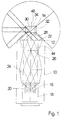
- Fig. 1 10 an elongated housing of square cross section designated.
- the housing 10 is at its upper end in FIG. 1 by a truncated pyramid-shaped end wall 12 and a housing 14 of beam deflecting means still to be completed.
- the end wall 12 forms the side surfaces of the stump of an (imaginary) four-sided pyramid square base. The inclination of the side surfaces is 45 ° to the base surface.
- the housing 14 is cuboid and has a square base that follows aligns the side walls of the pyramid.
- the housing 14 has four side surfaces, the Height is half the edge length of the base,
- a detector 16 is seated in the lower part of the housing 10 in FIG. 1.
- the detector 16 has square shape and is an image resolution detector with a grid of Detector elements,
- the detector 16 is in the usual way with a cooling device 18 provided and has a cold screen 20 cooled by the cooling device.
- a first imaging optical system in the form of a is seated in the housing 10 Primary lens 22 and a second imaging optical system in the form of a Detector lenses 24, the primary lens 22 produces in a manner to be described superimposed images of partial visual fields in an intermediate image plane 26.
- the Detector objective 24 forms the intermediate image plane 26 in one in the plane of the detector 16 lying image plane.
- the base of the housing 14 forms the square entrance pupil 28 for the Primary objective 22.
- This entrance pupil 28 lies in the focal plane of the object Primary lenses 22.
- the representation of the partial fields of view in the intermediate image plane therefore takes place in the telecentric beam path.
- the entrance pupil 28 is in four square partial pupils divided, the different partial visual fields assigned.
- Deflection prisms are located in the housing, of which a deflection prism 30 is closed in FIG see is.
- the deflection prism 30 has an isosceles right-angled cross section.
- a "Hypotenuse surface” 34 (FIG. 5) forms a reflective surface.
- One of the right angles “Catheter surfaces” 36 running towards one another form the entry surface of the Deflection prism 30.
- the other "catheter surface” 38 forms the exit surface.
- Fig.5 is to see a second deflection prism 32, sits next to the deflection prism 30 and the latter Entry surface 40 extends at right angles to entry surface 36 of deflection prism 30. 5 shows through the entry surface 40 at 45 ° to the reflective Hypotenuse surface of the deflecting prism 32.
- the exit surfaces 38, 42 of the Deflection prisms 30 and 32 each fill a partial pupil of the entry pupil 28.
- the primary lens 22 has an opening angle of 45 °.
- a micro-optical radiation deflection device 44 is located in the intermediate image plane arranged.
- This micro-optical beam deflection arrangement guides the Imaging beam path from one of the four pupils onto the detector objective 24, while the imaging beam paths from the other pupils do not differ from that Detector lens can be detected.
- One can see the mode of action of the micro-optical The best way to illustrate beam deflection is by looking at the beam paths traced backwards: Starting from a pixel in the image plane on the detector 16, an imaging beam path can be traced back to a conjugate one Pixel in the intermediate image plane. Through the micro-optical beam deflection arrangement the imaging beam path can now optionally be directed onto one of the partial pupils become.
- the micro-optical beam deflection arrangement 44 can, for example, similar to that in FIG. 4 DE 199 04 914 A1 is shown to be constructed with two microlens grids which against each other in two mutually perpendicular directions by one step each are adjustable.
- a (imaginary) cube 46 is shown in FIG.
- the all-round finder described sits in the center of this imaginary cube 46.
- Fig.2 are the detector 16 and Axis of symmetry 48 of the all-round finder indicated.
- the cube 46 has six faces, namely the four "lateral" surfaces 50, 52, 54 and 56 parallel to the axis of symmetry 48 and two opposing surfaces 58 and 60 perpendicular to the axis of symmetry 48.
- the surfaces 58 and 60 are centered by the axis of symmetry 48 pierced.
- the lateral surfaces 50, 52, 54 and 56 extend parallel to the Edges of the square detector.
- the surface of the cube 45 defines 50 to 60 six rectangular partial fields of view. These partial fields of view adjoin each other and include the full room.
- Partial fields of view are detected by the all-round detector.
- the primary lens 22 has for each partial field of view a square pupil part and an opening angle of 45 °. If the beam path is deflected by 90 ° through a deflecting prism e.g. 30 a lateral surface, e.g. 50, the cube from the primary lens 22 detected.
- the different surfaces 50 to 60 of the cube 45 are optical axes 62, 64, 66, 68 and 70 and, for the sake of completeness, an optical axis 72 downwards in Fig. 2.
- Each imaging beam path of a partial field of view is optical Axis, e.g. 62, centered and has a square partial pupil as the entrance pupil and an opening angle of 45 °, so that it just covers the square partial field of view.
- the images of the partial fields of view are superimposed on the intermediate image level.
- the Partial pupil lies in the focal plane of the primary lens 22, so that the images of the Partial fields of view are generated in the telecentric beam path.
- the advantages of the deflection prisms, e.g. 30 are best seen in Fig.5.
- the Opening angle of the primary lens is 45 °. So there are rays 74, 76, 78 from + 45 ° to 0 ° to -45 °. If the reflective surface were a pure mirror, then strong vignetting would occur.
- Rays at the entrance surface 36 are broken towards the surface normal. You can see that so that the opening angle of the beams within the deflection prism 30 is greatly reduced and all rays hit the reflecting surface 34.
- the Exit surface 38 the rays are again broken away from the surface normal, so that they again form an opening angle of 45 °.
- the opening angle of the Imaging beam path in the deflecting prism reduced from 45 ° to approximately 10 °.
- the four available partial fields of view can, depending on the arrangement of the Deflection prisms 30 etc. used to monitor different fields of view become.
- Fig. 3 shows a possibility in which the all-round viewer has a panorama over 360 ° an opening angle of 90 °.
- the optical axes are the deflected imaging beam paths after the lateral surfaces 50, 52 54 and 56 of the Cube 46 aligned and designated as 62, 64, 66 and 68 in FIG.
- FIG.5 Such an arrangement is shown in Fig.5.
- the four deflection prisms of which in 5 only the deflection prisms 30 and 32 are visible, are held in the housing 14.
- the housing 14 has openings or windows 80 in front of the entry surfaces 36 of the Deflection prisms 30, 32, etc.
- a 5 open breakthrough or a window provided to the front in FIG.
- a window has a similar arrangement angularly offset about the axis of symmetry 48 the left side to the rear in Fig.5 and a window to the right in Fig.5, where a deflection prism sits behind each window.
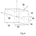
- Fig.4 illustrates the possibility that three of the four pupils in the four Available imaging beam paths by 90 ° to the rear, to the right and deflected forward in FIG. 4 and towards the surfaces 56, 54 and 52 of the cube 46 are aligned, while the third imaging beam path is parallel to the The axis of symmetry runs straight up and towards the surface 58 of the cube 46 is aligned. Then three deflection prisms are arranged in the partial pupils, while the space in front of the third pupil is free, so that the associated one Imaging beam path straight through the housing 14 and a provided in this Window goes through, which provides the optical axes 68, 66, 64 and 70 of the Imaging beam paths for the four connecting here again Partial fields.
- the axis of the half space is designated 82.
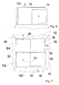
- Three deflection prisms 84, 86 and 88 sit in front of three partial pupils and in the housing 14 94.
- In front of the deflection prisms 84, 86 and 88 are in the side walls of the housing Window openings 94, 96 and 98.
- Each window extends in the area of associated pupil 90, 92, 94 over half of the respective side wall of the Housing 14.
- the through square partial pupils 90, 92 and 94 extending imaging beam paths through 90 ° deflected and pass through the windows 94, 96 with the optical axes 68, 66 and 64, respectively or 98. More specifically, the rays come from the different visual fields through the windows, are deflected by the deflecting prisms and fall through the Partial pupils on the primary lens 22 (Fig. 1).
- the space in the housing is empty.
- the fourth Imaging beam path passing through the sub-pupil passes through an at the top of the Housing 14 over the partial pupil 100 formed window 102 straight up, like is represented by the optical axis 70.
- One provided in the area of the partial pupil Window 104 has no function in this configuration.
- window 104 allows the optional realization of the "panorama” and "hyper-half space” version with one and the same housing.
- a deflection prism such as deflection prism 30 to be used in Fig.5.
- the micro-optical beam deflection device in the image plane allows very small ones Switching between the different partial pupils very quickly.
- the Switching can be done using piezo actuators. Scanning the whole Visual field e.g. a panorama or a half space can for example with a frequency of 1 kHz, the field of vision is practically continuous be recorded.
- the all-round finder described is very compact and, by omission moving macromechanical parts very robust and inexpensive.
- FIG. 8 shows the use of three all-round searches 106, 108 and 110 in the manner of FIG. 6 and 7 in a missile warning system on a fighter aircraft 112.
- the third all-round finder 110 sits on the tail.
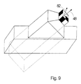
- Fig. 9 shows the attachment of the all-round finder at the wing end of the fighter plane.
- the all-round finders 106, 108 and 110 are with their Half-space axes 82 (FIG. 4) are arranged with respect to one another such that each partial field of view is recorded redundantly by two different all-round finders. That also allows Location of a detected object, e.g. of a missile, in space Triangulation.
Landscapes
- Engineering & Computer Science (AREA)
- Multimedia (AREA)
- Signal Processing (AREA)
- Length Measuring Devices By Optical Means (AREA)
Abstract
Description
- Fig. 1
- ist eine schematische Darstellung eines Rundumsuchers mit mehreren, mikrooptisch umschaltbaren Gesichtsfeldern.
- Fig.2
- veranschaulicht die Ausrichtung der zu beobachteten Gesichtsfelder nach einem Würfel.
- Fig.3
- veranschaulicht einen Rundumsucher, der mit vier umschaltbaren, nach den lateralen Seitenflächen des Würfels ausgerichteten Teilgesichtsfeldern ein Panorama überwacht.
- Fig.4
- veranschaulicht einen Rundumsucher, von dessen vier umschaltbaren Teilgesichtsfeldern drei nach lateralen Seitenflächen und eine nach der von der Symmetrieachse durchstoßenen Seitenfläche ausgerichtet ist.
- Fig.5
- zeigt einen Schnitt durch eine konstruktive Ausführung der strahlablenkenden Mittel mit zwei sichtbaren Umlenkprismen.
- Fig.6
- ist eine Seitenansicht der strahlablenkenden Mittel, bei einer Ausführung, bei welcher von den vier umschaltbaren Teilgesichtsfeldern drei nach lateralen Seitenflächen und eine nach der von der Symmetrieachse durchstoßenen Seitenfläche ausgerichtet ist.
- Fig.7
- zeigt einen Schnitt durch die strahlablenkenden Mittel von Fig.6 senkrecht zu der Symmetrieebene.
- Fig.8
- zeigt schematisch die Anwendung von drei Rundumsuchern der in Fig.7 dargestellten Art zur redundanten Überwachung des Vollraumes bei einem Flugkörperwarngerät an einem Kampfflugzeug.
- Fig.9
- zeigt die Montage eines Rundumsuchers der beschriebenen Art am Flügelende eines Kampfflugzeugs.
Claims (10)
- Vorrichtung zum Erfassen mehrerer Gesichtsfelder mittels eines einzigen bildauflösenden Detektors (16) von quadratischer Grundform mit einer zweidimensionalen Anordnung von Detektorelementen,(a) mit einem ersten abbildenden optischen System (22) mit einer Eintrittspupille und unterteilten strahlablenkenden Mitteln (30, 32; 84,86,88) objektseitig von der Eintrittspupille, durch welche die Eintrittspupille in Teilpupillen (90,92,94,100) unterteilt ist und Strahlen aus unterschiedlichen Gesichtsfeldern auf die verschiedenen Teilpupillen (90,92,94,100) gelenkt werden, wodurch das erste abbildende optische System (22) in einer Zwischenbildebene (26) überlagerte Bilder der verschiedenen Gesichtsfelder erzeugt,(b) mit einem zweiten abbildenden optischen System (24), durch welche die Zwischenbildebene (26) auf den bildauflösenden Detektor (16) abgebildet wird, und(c) mit einer in der Zwischenbildebene (26) angeordneten mikrooptischen Umschalteinrichtung (44), durch welche wahlweise jeweils nur die bilderzeugenden Strahlen eines der in der Zwischenbildebene (26) überlagerten Bilder der Gesichtsfelder auf das zweite abbildende optische System (24) geleitet werden,
dadurch gekennzeichnet, daß(d) die Vorrichtung als Rundumsucher ausgebildet ist, indem(e) das erste und das zweite abbildende optische System (22,24) eine gemeinsame Symmetrieachse (48) definieren,(f) der Detektor (16) und die Symmetrieachse (48) einen Würfel (46) definieren, welcher auf zwei gegenüberliegenden Seitenflächen (58,60) zentral von der Symmetrieachse (48) durchstoßen wird und dessen übrige, laterale. Seitenflächen (50,52,54,56) parallel zu je einer Kante des quadratischen Detektors (16) verlaufen, und(g) die strahlablenkenden Mittel (30,32;84,86,88) reflektierende Flächen (34) aufweisen durch welche Abbildungsstrahlengänge zur Abbildung von Gesichtsfeldern, die senkrecht zu Seitenflächen dieses Würfels (46) verlaufen, in Richtung der Symmetrieachse (48) umlenkbar sind, - Vorrichtung nach Anspruch 1, dadurch gekennzeichnet, daß das erste abbildende optische System (22) einen Öffnungswinkel von 45° hat.
- Vorrichtung nach Anspruch 2, dadurch gekennzeichnet, daß die Eintrittspupille des ersten abbildenden optischen Systems (22) quadratisch ist.
- Vorrichtung nach Anspruch 3, dadurch gekennzeichnet, daß die Eintrittspupille des ersten abbildenden optischen Systems von den strahlablenkenden Mitteln (30,32;84,86,88) gebildet ist.
- Vorrichtung nach Anspruch 4, dadurch gekennzeichnet, daß die Eintrittspupille in der objektseitigen Brennebene des ersten abbildenden optischen Systems (22) liegt, so daß die Abbildungsstrahlengänge für die verschiedenen Gesichtsfelder im telezentrischen Strahlengang parallel auf die Zwischenbildebene (26) fallen,
- Vorrichtung nach einem der Ansprüche 1 bis 5, dadurch gekennzeichnet, daß die reflektierenden Flächen (34) von den unter 45° zur Symmetrieachse geneigten Hypothenusenflächen rechtwinkliger Umlenkprismen (30) mit jeweils einer Eintrittsfläche (36) und einer dazu senkrechten Austrittsfläche (38) um die Symmetrieachse (48) winkelversetzt angeordnet sind.
- Vorrichtung nach Anspruch 6, dadurch gekennzeichnet, daß(a) die Umlenkprismen (30) in einem zu der Symmetrieachse (48) und dem. Würfel (46) ausgerichteten, mit quadratischen Fenstern (36; 94,96,98) in Richtung der zu beobachtenden Gesichtsfelder versehenen Gehäuse (14) angeordnet sind,(b) die zu dem ersten abbildenden System (22) hin offene Grundfläche des Gehäuses (14) die quadratische Eintrittspupille bildet, die in vier ebenfalls quadratische Teilpupillen (90,92,94,100) aufgeteilt ist und(c) die Austrittsflächen (38) der Umlenkprismen (30) jeweils eine der Teilpupillen überdecken.
- Vorrichtung nach einem der Ansprüche 1 bis 7, dadurch gekennzeichnet, daß die Abbildungsstrahlengänge nach den vier zur Symmetrieachse (48) parallelen, lateralen Seitenflächen (50,52,54,56) des Würfels (46) ausgerichtet sind.
- Vorrichtung nach einem der Ansprüche 1 bis 7, dadurch gekennzeichnet, daß drei Abbildungsstrahlengänge nach drei zur Symmetrieachse (48) parallelen Seitenflächen (56,54,52) ausgerichtet sind und ein vierter Abbildungsstrahlengang parallel zur Richtung der Symmetrieachse (48) verläuft.
- System mit drei räumlich getrennten Vorrichtungen nach den Ansprüchen 8 oder/und 9, dadurch gekennzeichnet, daß jedes Teilgesichtsfeld durch jeweils zwei der drei Vorrichtungen redundant und stereoskopisch erfasst wird.
Applications Claiming Priority (2)
| Application Number | Priority Date | Filing Date | Title |
|---|---|---|---|
| DE10232258 | 2002-07-16 | ||
| DE10232258A DE10232258A1 (de) | 2002-07-16 | 2002-07-16 | Vorrichtung zum Erfassen mehrerer Gesichtsfelder |
Publications (2)
| Publication Number | Publication Date |
|---|---|
| EP1383313A1 true EP1383313A1 (de) | 2004-01-21 |
| EP1383313B1 EP1383313B1 (de) | 2005-08-10 |
Family
ID=29762010
Family Applications (1)
| Application Number | Title | Priority Date | Filing Date |
|---|---|---|---|
| EP03008678A Expired - Lifetime EP1383313B1 (de) | 2002-07-16 | 2003-04-16 | Vorrichtung zum Erfassen eines gro en Gesichtsfeldes |
Country Status (2)
| Country | Link |
|---|---|
| EP (1) | EP1383313B1 (de) |
| DE (2) | DE10232258A1 (de) |
Citations (4)
| Publication number | Priority date | Publication date | Assignee | Title |
|---|---|---|---|---|
| DE19742462A1 (de) * | 1997-09-26 | 1999-04-01 | Bodenseewerk Geraetetech | Einrichtung zur Erfassung mehrerer Gesichtsfelder mittels eines bildauflösenden Detektors |
| US5975710A (en) * | 1997-06-06 | 1999-11-02 | Luster; Spencer D. | Optical image field splitting system |
| DE19904914A1 (de) * | 1999-02-06 | 2000-08-10 | Bodenseewerk Geraetetech | Bildauflösende Detektoranordnung |
| GB2368221A (en) * | 2000-08-31 | 2002-04-24 | Lee Scott Friend | Camera apparatus having both omnidirectional and normal view imaging modes. |
-
2002
- 2002-07-16 DE DE10232258A patent/DE10232258A1/de not_active Withdrawn
-
2003
- 2003-04-16 DE DE50300940T patent/DE50300940D1/de not_active Expired - Lifetime
- 2003-04-16 EP EP03008678A patent/EP1383313B1/de not_active Expired - Lifetime
Patent Citations (4)
| Publication number | Priority date | Publication date | Assignee | Title |
|---|---|---|---|---|
| US5975710A (en) * | 1997-06-06 | 1999-11-02 | Luster; Spencer D. | Optical image field splitting system |
| DE19742462A1 (de) * | 1997-09-26 | 1999-04-01 | Bodenseewerk Geraetetech | Einrichtung zur Erfassung mehrerer Gesichtsfelder mittels eines bildauflösenden Detektors |
| DE19904914A1 (de) * | 1999-02-06 | 2000-08-10 | Bodenseewerk Geraetetech | Bildauflösende Detektoranordnung |
| GB2368221A (en) * | 2000-08-31 | 2002-04-24 | Lee Scott Friend | Camera apparatus having both omnidirectional and normal view imaging modes. |
Also Published As
| Publication number | Publication date |
|---|---|
| DE50300940D1 (de) | 2005-09-15 |
| DE10232258A1 (de) | 2004-02-05 |
| EP1383313B1 (de) | 2005-08-10 |
Similar Documents
| Publication | Publication Date | Title |
|---|---|---|
| EP0578129B1 (de) | Bilderfassende Sensoreinheit | |
| DE69727102T2 (de) | Integrierte hochauflösende Rundum-Sensoroptik | |
| DE2156617C3 (de) | Einrichtung zur Bestimmung der Lage der Ebene maximaler Amplitude einer Ortsfrequenz, beispielsweise bei einem Entfernungsmesser | |
| DE102011010262B4 (de) | Optisches Beobachtungsgerät mit wenigstens zwei jeweils einen Teilstrahlengang aufweisenden optischen Übertragungskanälen | |
| DE10349590A1 (de) | Vermessungsinstrument | |
| EP1359452A1 (de) | Konfokales Mikroskop mit zwei Mikrolinsenarrays und einem Lochblendenarray | |
| DE60215223T2 (de) | Satellitengestütztes optisches beobachtungsinstrument mit zwei teleskopen | |
| DE19742462A1 (de) | Einrichtung zur Erfassung mehrerer Gesichtsfelder mittels eines bildauflösenden Detektors | |
| WO2020193581A1 (de) | Vorrichtung mit einer multiaperturabbildungsvorrichtung zur erzeugung einer tiefenkarte | |
| DE4420422C2 (de) | Technisches Komplexauge für dynamisches maschinelles Sehen | |
| DE3110296A1 (de) | "scharfeinstellungsdetektor" | |
| DE4035144A1 (de) | Optisches strahlenteilersystem zur erzeugung einer mehrzahl von reellen abbildungen | |
| DE102008019850A1 (de) | Vorrichtung und Verfahren zum Beleuchten einer Objektszene | |
| DE19535969A1 (de) | Mehrfach abbildendes Linsensystem | |
| DE10135222A1 (de) | Vorrichtung zum Erfassen einer Objektszene | |
| DE69108974T2 (de) | Abbildungs- und Überwachungsvorrichtung mit Matrixsensor. | |
| AT514174A1 (de) | Kamerasystem zur Herstellung von Panoramaaufnahmen | |
| EP1383313B1 (de) | Vorrichtung zum Erfassen eines gro en Gesichtsfeldes | |
| DE2201092B2 (de) | Einrichtung zur Bestimmung der relativen Lage der Ebene maximaler Amplitude einer Ortsfrequenz | |
| EP0916971A2 (de) | Schaltbares, mikrooptisches Strahlenumlenksystem | |
| EP1377037B1 (de) | Optisches System mit umschaltbaren Gesichtsfeldern | |
| DE3117421A1 (de) | "optisches geraet zum analysieren eines raeumlichen felds und zum ermitteln der winkellage eines strahlenden gegenstands in diesem feld" | |
| DE3142186C1 (de) | Optomechanische zweidimensionale Abtastanordnung mit mehreren Beobachtungsfeldern | |
| DE10232259A1 (de) | Sucheranordnung zum Beobachten eines großen Raumwinkels mittels eines bildauflösenden Detektors | |
| DE102022134643B4 (de) | Beobachtungsinstrument zur Beobachtung eines Himmelskörpers |
Legal Events
| Date | Code | Title | Description |
|---|---|---|---|
| PUAI | Public reference made under article 153(3) epc to a published international application that has entered the european phase |
Free format text: ORIGINAL CODE: 0009012 |
|
| AK | Designated contracting states |
Kind code of ref document: A1 Designated state(s): AT BE BG CH CY CZ DE DK EE ES FI FR GB GR HU IE IT LI LU MC NL PT RO SE SI SK TR |
|
| AX | Request for extension of the european patent |
Extension state: AL LT LV MK |
|
| 17P | Request for examination filed |
Effective date: 20031205 |
|
| 17Q | First examination report despatched |
Effective date: 20040322 |
|
| AKX | Designation fees paid |
Designated state(s): DE FR GB IT |
|
| GRAP | Despatch of communication of intention to grant a patent |
Free format text: ORIGINAL CODE: EPIDOSNIGR1 |
|
| RAP1 | Party data changed (applicant data changed or rights of an application transferred) |
Owner name: DIEHL BGT DEFENCE GMBH & CO.KG |
|
| RTI1 | Title (correction) |
Free format text: DEVICE FOR DETECTING A LARGE FIELD OF VIEW |
|
| GRAS | Grant fee paid |
Free format text: ORIGINAL CODE: EPIDOSNIGR3 |
|
| GRAA | (expected) grant |
Free format text: ORIGINAL CODE: 0009210 |
|
| AK | Designated contracting states |
Kind code of ref document: B1 Designated state(s): DE FR GB IT |
|
| REG | Reference to a national code |
Ref country code: GB Ref legal event code: FG4D Free format text: NOT ENGLISH |
|
| REF | Corresponds to: |
Ref document number: 50300940 Country of ref document: DE Date of ref document: 20050915 Kind code of ref document: P |
|
| GBT | Gb: translation of ep patent filed (gb section 77(6)(a)/1977) |
Effective date: 20050920 |
|
| ET | Fr: translation filed | ||
| PLBE | No opposition filed within time limit |
Free format text: ORIGINAL CODE: 0009261 |
|
| STAA | Information on the status of an ep patent application or granted ep patent |
Free format text: STATUS: NO OPPOSITION FILED WITHIN TIME LIMIT |
|
| 26N | No opposition filed |
Effective date: 20060511 |
|
| PGFP | Annual fee paid to national office [announced via postgrant information from national office to epo] |
Ref country code: DE Payment date: 20130619 Year of fee payment: 11 Ref country code: GB Payment date: 20130418 Year of fee payment: 11 |
|
| PGFP | Annual fee paid to national office [announced via postgrant information from national office to epo] |
Ref country code: IT Payment date: 20130429 Year of fee payment: 11 Ref country code: FR Payment date: 20130515 Year of fee payment: 11 |
|
| REG | Reference to a national code |
Ref country code: DE Ref legal event code: R119 Ref document number: 50300940 Country of ref document: DE |
|
| GBPC | Gb: european patent ceased through non-payment of renewal fee |
Effective date: 20140416 |
|
| REG | Reference to a national code |
Ref country code: FR Ref legal event code: ST Effective date: 20141231 |
|
| PG25 | Lapsed in a contracting state [announced via postgrant information from national office to epo] |
Ref country code: GB Free format text: LAPSE BECAUSE OF NON-PAYMENT OF DUE FEES Effective date: 20140416 Ref country code: DE Free format text: LAPSE BECAUSE OF NON-PAYMENT OF DUE FEES Effective date: 20141101 |
|
| PG25 | Lapsed in a contracting state [announced via postgrant information from national office to epo] |
Ref country code: FR Free format text: LAPSE BECAUSE OF NON-PAYMENT OF DUE FEES Effective date: 20140430 |
|
| PG25 | Lapsed in a contracting state [announced via postgrant information from national office to epo] |
Ref country code: IT Free format text: LAPSE BECAUSE OF NON-PAYMENT OF DUE FEES Effective date: 20140416 |