EP1383312A1 - Camera device and electronic device having the camera device - Google Patents
Camera device and electronic device having the camera device Download PDFInfo
- Publication number
- EP1383312A1 EP1383312A1 EP20020722770 EP02722770A EP1383312A1 EP 1383312 A1 EP1383312 A1 EP 1383312A1 EP 20020722770 EP20020722770 EP 20020722770 EP 02722770 A EP02722770 A EP 02722770A EP 1383312 A1 EP1383312 A1 EP 1383312A1
- Authority
- EP
- European Patent Office
- Prior art keywords
- data
- compression
- section
- output
- digital picture
- Prior art date
- Legal status (The legal status is an assumption and is not a legal conclusion. Google has not performed a legal analysis and makes no representation as to the accuracy of the status listed.)
- Withdrawn
Links
Images



Classifications
-
- H—ELECTRICITY
- H04—ELECTRIC COMMUNICATION TECHNIQUE
- H04N—PICTORIAL COMMUNICATION, e.g. TELEVISION
- H04N5/00—Details of television systems
- H04N5/76—Television signal recording
- H04N5/765—Interface circuits between an apparatus for recording and another apparatus
- H04N5/77—Interface circuits between an apparatus for recording and another apparatus between a recording apparatus and a television camera
- H04N5/772—Interface circuits between an apparatus for recording and another apparatus between a recording apparatus and a television camera the recording apparatus and the television camera being placed in the same enclosure
-
- H—ELECTRICITY
- H04—ELECTRIC COMMUNICATION TECHNIQUE
- H04N—PICTORIAL COMMUNICATION, e.g. TELEVISION
- H04N19/00—Methods or arrangements for coding, decoding, compressing or decompressing digital video signals
-
- H—ELECTRICITY
- H04—ELECTRIC COMMUNICATION TECHNIQUE
- H04N—PICTORIAL COMMUNICATION, e.g. TELEVISION
- H04N23/00—Cameras or camera modules comprising electronic image sensors; Control thereof
- H04N23/60—Control of cameras or camera modules
- H04N23/665—Control of cameras or camera modules involving internal camera communication with the image sensor, e.g. synchronising or multiplexing SSIS control signals
-
- H—ELECTRICITY
- H04—ELECTRIC COMMUNICATION TECHNIQUE
- H04N—PICTORIAL COMMUNICATION, e.g. TELEVISION
- H04N7/00—Television systems
- H04N7/14—Systems for two-way working
- H04N7/141—Systems for two-way working between two video terminals, e.g. videophone
- H04N7/148—Interfacing a video terminal to a particular transmission medium, e.g. ISDN
Definitions
- the present invention relates to a camera apparatus, and in particular, the present invention relates to a camera apparatus suitable for use with a picture communication apparatus having still picture filming functions and moving picture filming functions such as in TV telephones. Furthermore, the present invention relates to an electronic apparatus comprising the camera apparatus typified by picture communication apparatus.
- moving picture compression schemes used for bidirectional moving picture communication such as by TV telephones fall under simple profile level 1 by MPEG-4, which is an international standard scheme, and the resolution for corresponding picture data is QCIF (176 pixels * 144 lines).
- the number of horizontal pixels and the number of vertical lines are both around 100 to approximately 200 . Therefore, when moving picture filmed with a camera apparatus is displayed on a display device, QCIF is a sufficient resolution level for the moving picture data.
- QCIF is still an adequate resolution level for moving picture data that camera apparatus mounted in communication terminals requires.
- still picture data should ideally have higher resolution than QCIF, such as VGA (640 pixels * 480 lines).
- the first prior art employs a configuration comprising an imaging section which changes signals of the filmed object into signals for low-resolution moving pictures and signals for high-resolution still pictures, a compression section which performs moving picture compression and still picture compression, a control section, and a transmission section.
- the control section instructs the imaging section and the compression section as to the operation mode for moving pictures and for still pictures.
- the imaging section following the instruction from the control section, outputs picture signals.
- the compression section following the instruction from the control section, performs compression adequate for moving pictures and still pictures respectively and outputs the compressed data to the transmission section.
- This prior art employs a configuration comprising an imaging section, a memory which stores picture data output from the imaging section, a signal processing section which performs color conversion and ⁇ conversion and such, a compression circuit which performs JPEG compression and such, and an external recorder medium.
- a pathway is provided to directly transfer data from the memory that stores picture data to the external recorder medium; this pathway is used when live picture data from the imaging section is recorded into the external memory medium.
- compression data is recorded into the external recorder medium, the data is supplied from the memory storing picture data to the signal processing circuit, and from the signal processing circuit through the compression circuit, the compression data is recorded into the external recorder medium.
- the present invention aims to provide a camera apparatus that can simplify the circuit configuration of an external apparatus that receives digital picture data and that can simplify circuit control, and an electronic apparatus that comprises the camera apparatus.
- the above aim can be achieved by inputting digital picture data output from an image signal processor means into a first pathway with a compressor means and another pathway without a compressor means, and by outputting the compression data input through the first pathway via a compressor means and the digital picture data input through another pathway to outside at the same timing through the same signal line.
- FIG.1 is a block diagram showing a configuration of an electronic apparatus comprising a camera apparatus according to Embodiment 1 of the present invention.
- the electronic apparatus shown in FIG.1 is composed of camera 1 that films an object and outputs digital picture data, moving picture compression extender 2 that compresses the digital picture data output from camera 1 and extends the compression data, CPU 3 that controls the entire electronic apparatus, display 4 that displays digital image data, memory 5 that memorizes data, and bus 30 that electrically connects each part.
- lens 10 injects the light from the object into imaging device 11.
- Imaging device 11 photoelectrically converts the injected light and then outputs image signal 100 to image signal processor 12 .
- Image signal processor 12 performs A/D conversion and color conversion and such on video signal 100 to generate digital picture data 101 consisting of luminance data and color difference data and such, which is then output to compressor 13 and resolution changer 16.
- Compressor 13 compresses digital picture data 101 by a publicly-known still image compression format such as the JPEG scheme and outputs compression data 102 to buffer 17 .
- Buffer 17 buffers compression data 102, which is then output to output 14.
- resolution changer 16 reduces the resolution of digital picture data 101 and generates new digital picture data 104 with a reduced information volume, which is then output to output 14.
- Output 14 chooses either one of digital picture data 104 with reduced resolution and buffered compression data 105, which is then output as output data 106. This choice is made in accordance with the instruction of choice signal 108 from control interface 18 that has received control signal 300 from CPU 3.
- Synchronization signal generator 15 is provided in camera 1. Synchronization signal 103 generated from this synchronization signal generator 15 is input into imaging device 11, image signal processor 12, compressor 13, output 14, resolution changer 16, and into moving picture compression extender 2 that will be described later. Synchronization signal 103 consists of a vertical synchronization signal, a horizontal synchronization signal, a data clock and such.
- input 20 inputs output data 106, which has been output from output 14 of camera 1, into buffer 21, whereupon buffer 21 stores the data.
- MPEG-4 codec 22 video-codes and compresses digital picture data 104 by MPEG-4 or extends video-coded data into original digital picture data by way of decoding.
- An MPEG-4 format is employed here; nevertheless, other moving picture compression formats such as H.263 and MPEG-2 can be employed as well.
- Host interface 23 inputs a control signal from CPU 3 into MPEG-4 codec 22 and executes compression, while following control from CPU 3 and transferring the data stored in buffer 21 and the M-PEG data compressed in MPEG-4 codec 22 to display 4 and recorder 5. It is also possible to transfer the MPEG data memorized in recorder 5 to MPEG-4 codec 22 for extension.
- the data stored in buffer 21 is digital picture data 104
- this digital picture data 104 is compressed in MPEG-4 codec 22 to realize TV-telephone functions and such. Otherwise, digital picture data 104 is transferred to display 4 for camera picture display.
- the data stored in buffer 21 is compression data 105
- the data is transferred by control of CPU 3 through host interface 23 to recorder 5 and memorized.
- Imaging device 11, image signal processor 12, compressor 13, buffer 17, resolution changer 16, and output 14 output signals in synch with the same synchronization signal 103 generated from synchronization signal generator 15. That is, imaging device 11 outputs image signal 100 that is in synch with synchronization signal 103 generated from synchronization signal generator 15 to image signal processor 12. Image signal processor 12 outputs digital picture data 101 to compressor 13 and resolution changer 16 in parallel in synch with synchronization signal 103.
- the first pathway A through compressor 13 and buffer 17 and the second pathway B through resolution changer 16 yet lacking compressor 13 are provided, and digital picture data 101 from video signal processor 12 is input in parallel into the first pathway A and the second pathway B.
- Compressor 13 compresses digital picture data 101 and outputs compression data 102 to buffer 17 in synch with synchronization signal 103. Meanwhile, resolution changer 16 also outputs digital picture data 104 to output 14 in synch with synchronization signal 103.
- Output 14 outputs either digital picture data 104 or compressed data 105 as output data 106, and in either case, it is output to moving picture compression extender 2 in synch with synchronization signal 103 through the same signal line.
- FIG.2 and FIG.3 each show an example of a signal timing of a camera apparatus according to above Embodiment 1.
- the horizontal axis represents time.
- signals identical to those in FIG.1 will be assigned the same codes.
- FIG.2 illustrates an example of a signal timing in a case where digital picture data is output in a camera apparatus according to above Embodiment 1. Shown here is a timing that digital picture data 104 is output in synch with synchronization signal 103 (a data clock, a vertical synchronization signal, and a horizontal synchronization signal).
- synchronization signal 103 a data clock, a vertical synchronization signal, and a horizontal synchronization signal.
- FIG.3 illustrates an example of a signal timing in a case where digital compression data is output in a camera apparatus according to above Embodiment 1. Shown here is a timing that compression data 105 is output in synchwith synchronization signal 103 (a data clock, a vertical synchronization signal, and a horizontal synchronization signal).
- synchwith synchronization signal 103 a data clock, a vertical synchronization signal, and a horizontal synchronization signal.
- the circuit configuration and control on the receiver side that receives output data can be unified irrespective of digital picture data 104 or compression data 105, whichmakes it possible to reduce the circuit scale and simplify the circuit control.
- Camera 1 is capable of selectively outputting uncompressed digital picture data 104 and compression data 105 compressed by compressor 13. Consequently, when display 4 displays pictures from camera 1, uncompressed digital picture data 104 is chosen through output 14 and output to moving picture compression extender 2 and transferred to display 4, so that there is no need to provide a means for extending compression data in the electronic apparatus. As a result, reduction in the circuit scale on the receiver side that receives output data 106 and simplification of the circuit control become possible.
- Embodiment 1 the resolution of imaging device 11 is VG and digital picture data 101 having resolution of VGA is converted into for instance digital picture data 104 having resolution of CIF, the data transfer speed upon outputting digital picture data 104 from output data 106 can be moderated and power consumption can be saved as well.
- compression data 105 is output from output data 106, it is possible to output compression data corresponding to pictures of resolution up to VGA by the same timing as when digital picture data 104 is output.
- camera 1 of Embodiment 1 With simplified arrangement and interface, it is possible tominimize power consumption and obtain moving picture data of adequate resolution for communication terminal apparatus typified by mobile phones and compression data of higher resolution than moving picture data.
- resolution changer 16 is provided on the second route B; nevertheless, the provision is not essential.
- FIG.4 is a diagram illustrating an example of a signal timing in a camera apparatus according to Embodiment 1.
- the horizontal axis represents time.
- signals identical to those in FIG.1 will be assigned the same codes.
- one cycle of a vertical synchronization signal 103a is called a frame.
- imaging device outputs image signal 100 in synch with vertical synchronization signal 103a to image signal processor 12 as illustrated in frames a1 to a6.
- Image signal processor 12 performs A/D conversion and color conversion and such on image signal 100 to generate digital picture data 101 consisting of luminance data and color-difference data and such, which is then output to compressor 13 and to resolution changer 16 in parallel, as shown in frames b1 to b6.
- Compressor 13 compresses digital picture data 101 by for example a JPEG scheme and outputs compression data 102 to buffer 17 as illustrated in frames d1 to d6. Normally, compression data 102 that compressor 13 outputs does not generate at a constant pace in time but on a burst basis. So buffer 17 buffers compression data 102 over the period of one frame and, as illustrated in frames e0 to e5, outputs burst-generated compression data 102 to output 14 at a pace constant in time.
- Resolution changer 16 reduces the resolution of digital picture data 101 and generates new digital picture data 104 with a reduced data volume, which is then output to output 14 as illustrated in frames c1 to c6.
- output 14 chooses either one of digital picture data 104 after resolution change and compression data 105 after buffering, which is then output as output data 106.
- control interface 18 outputs the instruction of control signal 300 received from CPU 3 to output 14 as choice signal 14 in synch with vertical synchronization signal 103.
- compression data 102 is buffered over the period of one frame, and compression data 102 that generates on a burst basis is output to output 14 at a constant pace in time, and so when compression data 105 is output from camera 1, continuous compression data 105 in synch with synchronization signal 103 can be obtained, which, provided for instance that the compression scheme is JPEG, can be handled as motion JPEG data.
- the compression scheme is JPEG
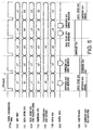
- FIG.5 is a diagram illustrating another example of a signal timing in a camera apparatus according to Embodiment 1.
- the horizontal axis represents time.
- signals identical to those in FIG.1 are assigned the same codes, and their detailed explanations are omitted.
- Control interface 18 outputs the instruction of control signal 300 received from CPU 3 to compressor 13 as compression data hold instruction signal 107 in synch with vertical synchronization signal 103a.
- compressor 13 Upon being instructed to hold the compression data through compression data hold instruction signal 107, compressor 13 stops outputting compression data 102 and stops renewing compression data 105 memorized in buffer 17. In addition, upon being instructed to renew compression data, compressor 13 starts outputting compression data 102 and starts renewing compression data 105 memorized in buffer17.
- compressor 13 can optionally stop and start renewing compression data memorized in buffer 17 by compression data hold signal 107, and so compression data 105, in which one screen of a moment of option is compressed, can be held by external instruction from CPU 3 and such. Accordingly, for example at the time of filming a still picture, it is possible to compress a specified filmed picture and thereafter hold this compression data and transfer this compression data at a time point of option.
- compressor 13 and buffer 17 are in constant operation; however, such configuration is also possible where these parts operate when output 14 chooses to output compression data 105. By this means power consumption can be minimized while camera 1 outputs digital picture data 104.
- compressor 13 needs to perform control in a way that makes the code volume of compression data 102 obtained by compressing one screen page smaller than a data volume that can be output from output data 106 over the period of one frame.
- a flag is provided in control interface 18 to indicate an error, so as to perform error notification to CPU through this flag.
- Embodiment 2 A case will be described here with Embodiment 2 where a camera apparatus according to the present invention is incorporated into a communication terminal apparatus with picture filming and image transmission/reception functions.
- FIG.6 is a block diagram showing a configuration of a communication terminal apparatus according to Embodiment 2 of the present invention.
- parts and signals identical to those in FIG.1 are assigned the same codes, and their detailed explanations are omitted.
- a communication terminal is composed of camera 1, moving picture compres s ion extender 2 , CPU3, display 4, recorder 5, radio section 6 that transmits/receives picture data and voice data in radio frequency, sound processor 7 that inputs/outputs sound data, and bus 30 that connects each part.
- antenna 60 transmits/receives a radio signal.
- RF section 61 down-converts a received signal to a baseband frequency and then outputs it to baseband signal processor 62, while up-converting a transmission signal output from baseband signal processor 62 into radio frequency and then outputting it to antenna 60.
- Baseband signal processor 62 demodulates the received signal output from RF section 61 and obtains a picture coding signal or sound coding signal (hereinafter "baseband signal" ) , while modulating the baseband signal and obtaining a transmission signal.
- baseband signal picture coding signal or sound coding signal
- Sound processor 7 encodes a sound signal into sound coding data and is composed of sound codec 70 that decodes a sound decoding signal into a sound signal, and speaker 71 that outputs the sound signal, and microphone 72 that receives sound and outputs a sound signal.
- CPU 3 outputs a sound coded signal that is output from sound codec 70 to baseband signal processor 62 as a transmission signal, or outputs a moving picture coded signal that is output from moving picture compression extender 2 to baseband signal processor 62 as a transmission signal.
- digital picture data corresponding to moving pictures having for instance a CIF resolution and compression data corresponding to still pictures having for instance resolution up to VGA can be obtained as the same output data 106, that is to say, by using the same signal line and at the same signal timing, thereby enabling bi-directional moving picture communication functions and still picture filming functions.
- Embodiment 2 has been described using a wireless communication terminal apparatus as an example; nevertheless, a camera apparatus according to the present invention is applicable to use with mobile telephones, mobile TV telephones, and mobile stations such as communication terminals with computer functions in mobile communication systems, or with cable-connected stationary telephones and TV telephones, and furthermore with information terminals with TV receivers, computers, and computer functions.
- both the digital picture data and the compression data are input into an external apparatus through the same signal line at the same signal timing, so that there is no need to provide separate circuits for receiving digital picture data and compression data. Consequently, it is possible to unify the circuit configuration and circuit control of external apparatus, so that the circuit scale can be reduced and the circuit control can be simplified.
- the present invention relates to a camera apparatus and suits for use with a picture communication apparatus comprising still picture filming functions and moving picture filming and communication functions such as in TV telephones. Furthermore, the present invention is suitable for use with an electronic apparatus comprising the above camera apparatus typified by picture communication apparatus.
Landscapes
- Engineering & Computer Science (AREA)
- Multimedia (AREA)
- Signal Processing (AREA)
- Computer Networks & Wireless Communication (AREA)
- Studio Devices (AREA)
- Television Signal Processing For Recording (AREA)
- Compression Or Coding Systems Of Tv Signals (AREA)
- Two-Way Televisions, Distribution Of Moving Picture Or The Like (AREA)
- Compression, Expansion, Code Conversion, And Decoders (AREA)
Abstract
Description
Claims (8)
- A camera apparatus comprising:an imaging device that outputs an filmed object as an image signal;an image signal processing section that converts the image signal output from said imaging device into digital picture data;a first pathway into which the digital picture data output from said image signal processing section is input, with a compression section provided on said first pathway to compress the digital picture data;another pathway into which the digital picture data output from said image signal processing section is input in parallel with said first pathway, without said compression section provided on said another pathway; andan output section that is connected to said first pathway and said another pathway that selectively outputs the compression data input from said first pathway with said compression section and the digital picture data input from said another pathway, using a same signal line at a same signal timing.
- The camera apparatus according to claim 1 further comprising a synchronization signal generating section that supplies a synchronization signal,
wherein the digital picture signal is output from said output section in synch with the synchronization signal, and
wherein the compression data is output from said output section in synch with the synchronization signal. - The camera apparatus according to claim 1,
wherein a resolution changing section is provided on said another pathway, said resolution changing section reducing a resolution of digital picture data and generating a second digital picture data with a resolution lower than a resolution of said imaging device, and
wherein said output section selectively outputs the second digital picture data and the compression data. - The camera apparatus according to claim 1, wherein a buffer section that memorizes the compression data is provided on said first pathway, said buffer section holding one frame period of the compression data output from said compression section and then sending the compression data to said output section at a regular pace in time.
- The camera apparatus according to claim 1,
wherein a buffer section that memorizes the compression data is provided on said first pathway;
wherein in accordance with a compression data hold instruction from an instruction section, said compression section pauses outputting the compression data to said output section and renewing the compression data memorized in said buffer section; and,
wherein in accordance with a compression data renewal instruction from said instruction section, said compression section resumes outputting said compression data to said output section and resumes renewing the compression data memorized in said buffer section. - The camera apparatus according to claim 1, wherein said compression section pauses operation while said output section outputs digital picture data input from another pathway.
- An electronic apparatus with a camera apparatus, said camera apparatus comprising:an imaging device that outputs an filmed object as an image signal;an image signal processing section that converts the image signal output from said imaging device into digital picture data;a first pathway into which the digital picture data output from said image signal processing section is input, with a compression section provided on said pathway to compress the digital picture data;another pathway into which the digital picture data output from said image signal processing section is input in parallel with said first pathway, without said compression section provided on said another pathway; andan output section connected to said first pathway and said another pathway that selectively outputs the compression data input from said first pathway with said compression section and the digital picture data input from said another pathway, using a same signal line at a same signal timing.
- A data transfer method for use with a camera apparatus that outputs digital picture data generated by taking a film object and compression picture data in which the digital picture data is compressed, comprising the steps of:converting an image signal output by taking the film object with an imaging device into digital picture data;generating compression data by compressing the digital picture data; andoutputting selectively one of the compression data and the digital picture data through a same signal line at a same timing.
Applications Claiming Priority (3)
| Application Number | Priority Date | Filing Date | Title |
|---|---|---|---|
| JP2001130622A JP4028694B2 (en) | 2001-04-27 | 2001-04-27 | CAMERA DEVICE AND ELECTRONIC DEVICE HAVING THE CAMERA DEVICE |
| JP2001130622 | 2001-04-27 | ||
| PCT/JP2002/004115 WO2002089470A1 (en) | 2001-04-27 | 2002-04-25 | Cemera device and electronic device having the camera device |
Publications (2)
| Publication Number | Publication Date |
|---|---|
| EP1383312A1 true EP1383312A1 (en) | 2004-01-21 |
| EP1383312A4 EP1383312A4 (en) | 2006-11-15 |
Family
ID=18978958
Family Applications (1)
| Application Number | Title | Priority Date | Filing Date |
|---|---|---|---|
| EP02722770A Withdrawn EP1383312A4 (en) | 2001-04-27 | 2002-04-25 | CAMERA DEVICE AND ELECTRONIC DEVICE COMPRISING THIS CAMERA DEVICE |
Country Status (5)
| Country | Link |
|---|---|
| US (1) | US7365781B2 (en) |
| EP (1) | EP1383312A4 (en) |
| JP (1) | JP4028694B2 (en) |
| CN (1) | CN1210947C (en) |
| WO (1) | WO2002089470A1 (en) |
Families Citing this family (11)
| Publication number | Priority date | Publication date | Assignee | Title |
|---|---|---|---|---|
| US8072643B2 (en) | 2004-12-17 | 2011-12-06 | Sanyo Electric Co., Ltd. | Image processing apparatus |
| US8885208B2 (en) * | 2006-07-21 | 2014-11-11 | Adobe Systems Incorporated | Progressive refinement of an edited image using secondary high resolution image processing |
| KR100902419B1 (en) * | 2007-06-25 | 2009-06-11 | 주식회사 코아로직 | An image processing apparatus and method for displaying a captured image without time delay, and a computer-readable recording medium that includes the program and the method. |
| KR100902420B1 (en) * | 2007-06-25 | 2009-06-11 | 주식회사 코아로직 | An image processing apparatus and method for displaying a captured image without time delay, and a computer-readable recording medium that includes the program and the method. |
| KR100902421B1 (en) * | 2007-06-25 | 2009-06-11 | 주식회사 코아로직 | An image processing apparatus and method for displaying a captured image without time delay, and a computer-readable recording medium that includes the program and the method. |
| KR100935541B1 (en) | 2007-12-28 | 2010-01-07 | 엠텍비젼 주식회사 | Image signal processing method and signal processing device performing the same |
| US8487963B1 (en) | 2008-05-30 | 2013-07-16 | Adobe Systems Incorporated | Preview representation of pixels effected by a brush tip area |
| JP2013008270A (en) * | 2011-06-27 | 2013-01-10 | Renesas Electronics Corp | Parallel arithmetic unit and microcomputer |
| WO2013121616A1 (en) * | 2012-02-17 | 2013-08-22 | オリンパスメディカルシステムズ株式会社 | Endoscopy device |
| US10437514B2 (en) | 2017-10-02 | 2019-10-08 | Micron Technology, Inc. | Apparatuses and methods including memory commands for semiconductor memories |
| US10467158B2 (en) | 2017-11-29 | 2019-11-05 | Micron Technology, Inc. | Apparatuses and methods including memory commands for semiconductor memories |
Family Cites Families (26)
| Publication number | Priority date | Publication date | Assignee | Title |
|---|---|---|---|---|
| US4888795A (en) | 1987-06-30 | 1989-12-19 | Nec Corporation | Videotelephone apparatus for transmitting high and low resolution video signals over telephone exchange lines |
| EP0390421B1 (en) * | 1989-03-30 | 1994-07-06 | Canon Kabushiki Kaisha | Still video camera |
| JP2549737B2 (en) * | 1989-12-06 | 1996-10-30 | 三菱電機株式会社 | Video signal processing circuit |
| DE69131369T2 (en) | 1990-07-31 | 1999-12-16 | Canon K.K., Tokio/Tokyo | Image processing apparatus and method |
| JPH06315105A (en) | 1993-04-28 | 1994-11-08 | Nikon Corp | Camera device |
| JP3307085B2 (en) * | 1993-12-10 | 2002-07-24 | ソニー株式会社 | Communication method and electronic equipment |
| JPH07322114A (en) | 1994-05-20 | 1995-12-08 | Canon Inc | Imaging device |
| US6018363A (en) | 1994-04-28 | 2000-01-25 | Canon Kabushiki Kaisha | Image sensing apparatus with optical-axis deflecting device |
| JPH08331537A (en) | 1995-06-01 | 1996-12-13 | Matsushita Electric Ind Co Ltd | Video communication device |
| JP3513554B2 (en) | 1995-07-06 | 2004-03-31 | 株式会社日立製作所 | Imaging device and method |
| US20010017658A1 (en) * | 1996-02-29 | 2001-08-30 | Toshihisa Kuroiwa | Frame memory device and method |
| US20050041132A1 (en) * | 1996-12-02 | 2005-02-24 | Nikon Corporation | Electronic camera |
| DE69736347T2 (en) | 1997-05-09 | 2007-07-12 | Stmicroelectronics S.R.L., Agrate Brianza | Digital photographing apparatus with an image processing apparatus |
| JP3610195B2 (en) | 1997-07-04 | 2005-01-12 | キヤノン株式会社 | Imaging device |
| JPH1132240A (en) | 1997-07-09 | 1999-02-02 | Olympus Optical Co Ltd | Electronic image-pickup device |
| JP3517564B2 (en) | 1997-09-30 | 2004-04-12 | キヤノン株式会社 | Imaging device and imaging system |
| US6229578B1 (en) * | 1997-12-08 | 2001-05-08 | Intel Corporation | Edge-detection based noise removal algorithm |
| JPH11261879A (en) | 1998-03-12 | 1999-09-24 | Nikon Corp | Electronic camera with continuous shooting function |
| US20020106199A1 (en) * | 1998-05-27 | 2002-08-08 | Osamu Ikeda | Image signal recording/reproduction apparatus, method employed therein, and image signal recording apparatus |
| JP4158245B2 (en) | 1998-07-17 | 2008-10-01 | ソニー株式会社 | Signal processing device |
| JP4282113B2 (en) * | 1998-07-24 | 2009-06-17 | オリンパス株式会社 | IMAGING DEVICE, IMAGING METHOD, AND RECORDING MEDIUM CONTAINING IMAGING PROGRAM |
| JP3443341B2 (en) * | 1998-10-19 | 2003-09-02 | 三洋電機株式会社 | Digital camera |
| JP3424642B2 (en) * | 1999-04-28 | 2003-07-07 | ミノルタ株式会社 | Image processing apparatus, image reading apparatus and image forming apparatus equipped with the same, and image processing method |
| JP4378804B2 (en) | 1999-09-10 | 2009-12-09 | ソニー株式会社 | Imaging device |
| JP4304795B2 (en) * | 1999-09-28 | 2009-07-29 | 株式会社ニコン | Electronic camera |
| WO2001026051A1 (en) * | 1999-10-04 | 2001-04-12 | Hamamatsu Photonic K.K. | Camera system for high-speed image processing |
-
2001
- 2001-04-27 JP JP2001130622A patent/JP4028694B2/en not_active Expired - Fee Related
-
2002
- 2002-04-25 CN CNB028014561A patent/CN1210947C/en not_active Expired - Fee Related
- 2002-04-25 EP EP02722770A patent/EP1383312A4/en not_active Withdrawn
- 2002-04-25 US US10/312,339 patent/US7365781B2/en not_active Expired - Fee Related
- 2002-04-25 WO PCT/JP2002/004115 patent/WO2002089470A1/en not_active Ceased
Also Published As
| Publication number | Publication date |
|---|---|
| JP4028694B2 (en) | 2007-12-26 |
| CN1210947C (en) | 2005-07-13 |
| CN1462544A (en) | 2003-12-17 |
| JP2002330326A (en) | 2002-11-15 |
| US20030151671A1 (en) | 2003-08-14 |
| US7365781B2 (en) | 2008-04-29 |
| EP1383312A4 (en) | 2006-11-15 |
| WO2002089470A1 (en) | 2002-11-07 |
Similar Documents
| Publication | Publication Date | Title |
|---|---|---|
| US6038257A (en) | Motion and still video picture transmission and display | |
| EP1429557B1 (en) | Video overlay device of mobile telecommunication terminal | |
| US7652692B2 (en) | Apparatus and method for photographing a moving picture | |
| US7365781B2 (en) | Camera apparatus and method for synchronized transfer of digital picture data and compressed digital picture data | |
| US7411617B2 (en) | Image processing apparatus, image processing method, recording medium, and program | |
| KR100821407B1 (en) | Image Information Processing System and Image Information Processing Method | |
| US20050254579A1 (en) | Image data compression device, electronic apparatus and image data compression method | |
| US20040235413A1 (en) | Mobile terminal having image processing function and method therefor | |
| US7705890B2 (en) | Apparatus and method for photographing an image in a wireless terminal | |
| US7606432B2 (en) | Apparatus and method for providing thumbnail image data on a mobile terminal | |
| US20050140790A1 (en) | Mobile communication terminal equipped with TV reception function | |
| WO2001033538A1 (en) | Display and video producing apparatus, and displaying method and video producing method | |
| KR100685300B1 (en) | Encoded data transfer method and imaging device performing the method | |
| JP2005303512A (en) | Camera and data transfer method | |
| JP4266477B2 (en) | Information processing apparatus and control method thereof | |
| US20070188600A1 (en) | Multi-stage media compression technique for power and storage efficiency | |
| KR20060000612A (en) | Apparatus, system and method for compressing rotated images | |
| JP2004140613A (en) | Image processing device, image processing method, and communication terminal device | |
| KR100669607B1 (en) | Display control device for each mode of mobile terminal | |
| KR20050041589A (en) | Method for taking moving picture in wireless phone | |
| KR100693587B1 (en) | Wireless communication terminal with high quality video and video processing and its method | |
| CN118138773A (en) | Image communication device, method and computer readable storage medium | |
| JP2004146940A (en) | Network system for video transmission | |
| JP2012120011A (en) | Moving image communication apparatus, digital video camera, recording media, and semiconductor integrated circuit | |
| KR20050122526A (en) | Picture-taking image saving method of mobile terminal |
Legal Events
| Date | Code | Title | Description |
|---|---|---|---|
| PUAI | Public reference made under article 153(3) epc to a published international application that has entered the european phase |
Free format text: ORIGINAL CODE: 0009012 |
|
| 17P | Request for examination filed |
Effective date: 20021209 |
|
| AK | Designated contracting states |
Kind code of ref document: A1 Designated state(s): AT BE CH CY DE DK ES FI FR GB GR IE IT LI LU MC NL PT SE TR |
|
| AX | Request for extension of the european patent |
Extension state: AL LT LV MK RO SI |
|
| A4 | Supplementary search report drawn up and despatched |
Effective date: 20061018 |
|
| RAP1 | Party data changed (applicant data changed or rights of an application transferred) |
Owner name: PANASONIC CORPORATION |
|
| 17Q | First examination report despatched |
Effective date: 20100322 |
|
| STAA | Information on the status of an ep patent application or granted ep patent |
Free format text: STATUS: THE APPLICATION IS DEEMED TO BE WITHDRAWN |
|
| 18D | Application deemed to be withdrawn |
Effective date: 20131101 |