WO2013121616A1 - Endoscopy device - Google Patents
Endoscopy device Download PDFInfo
- Publication number
- WO2013121616A1 WO2013121616A1 PCT/JP2012/073829 JP2012073829W WO2013121616A1 WO 2013121616 A1 WO2013121616 A1 WO 2013121616A1 JP 2012073829 W JP2012073829 W JP 2012073829W WO 2013121616 A1 WO2013121616 A1 WO 2013121616A1
- Authority
- WO
- WIPO (PCT)
- Prior art keywords
- illumination
- led
- light
- control unit
- endoscope apparatus
- Prior art date
Links
Images


Classifications
-
- A—HUMAN NECESSITIES
- A61—MEDICAL OR VETERINARY SCIENCE; HYGIENE
- A61B—DIAGNOSIS; SURGERY; IDENTIFICATION
- A61B1/00—Instruments for performing medical examinations of the interior of cavities or tubes of the body by visual or photographical inspection, e.g. endoscopes; Illuminating arrangements therefor
- A61B1/06—Instruments for performing medical examinations of the interior of cavities or tubes of the body by visual or photographical inspection, e.g. endoscopes; Illuminating arrangements therefor with illuminating arrangements
- A61B1/0638—Instruments for performing medical examinations of the interior of cavities or tubes of the body by visual or photographical inspection, e.g. endoscopes; Illuminating arrangements therefor with illuminating arrangements providing two or more wavelengths
-
- A—HUMAN NECESSITIES
- A61—MEDICAL OR VETERINARY SCIENCE; HYGIENE
- A61B—DIAGNOSIS; SURGERY; IDENTIFICATION
- A61B1/00—Instruments for performing medical examinations of the interior of cavities or tubes of the body by visual or photographical inspection, e.g. endoscopes; Illuminating arrangements therefor
- A61B1/00163—Optical arrangements
- A61B1/00186—Optical arrangements with imaging filters
-
- A—HUMAN NECESSITIES
- A61—MEDICAL OR VETERINARY SCIENCE; HYGIENE
- A61B—DIAGNOSIS; SURGERY; IDENTIFICATION
- A61B1/00—Instruments for performing medical examinations of the interior of cavities or tubes of the body by visual or photographical inspection, e.g. endoscopes; Illuminating arrangements therefor
- A61B1/06—Instruments for performing medical examinations of the interior of cavities or tubes of the body by visual or photographical inspection, e.g. endoscopes; Illuminating arrangements therefor with illuminating arrangements
- A61B1/0646—Instruments for performing medical examinations of the interior of cavities or tubes of the body by visual or photographical inspection, e.g. endoscopes; Illuminating arrangements therefor with illuminating arrangements with illumination filters
-
- A—HUMAN NECESSITIES
- A61—MEDICAL OR VETERINARY SCIENCE; HYGIENE
- A61B—DIAGNOSIS; SURGERY; IDENTIFICATION
- A61B1/00—Instruments for performing medical examinations of the interior of cavities or tubes of the body by visual or photographical inspection, e.g. endoscopes; Illuminating arrangements therefor
- A61B1/06—Instruments for performing medical examinations of the interior of cavities or tubes of the body by visual or photographical inspection, e.g. endoscopes; Illuminating arrangements therefor with illuminating arrangements
- A61B1/0655—Control therefor
-
- A—HUMAN NECESSITIES
- A61—MEDICAL OR VETERINARY SCIENCE; HYGIENE
- A61B—DIAGNOSIS; SURGERY; IDENTIFICATION
- A61B1/00—Instruments for performing medical examinations of the interior of cavities or tubes of the body by visual or photographical inspection, e.g. endoscopes; Illuminating arrangements therefor
- A61B1/06—Instruments for performing medical examinations of the interior of cavities or tubes of the body by visual or photographical inspection, e.g. endoscopes; Illuminating arrangements therefor with illuminating arrangements
- A61B1/0661—Endoscope light sources
- A61B1/0669—Endoscope light sources at proximal end of an endoscope
-
- A—HUMAN NECESSITIES
- A61—MEDICAL OR VETERINARY SCIENCE; HYGIENE
- A61B—DIAGNOSIS; SURGERY; IDENTIFICATION
- A61B1/00—Instruments for performing medical examinations of the interior of cavities or tubes of the body by visual or photographical inspection, e.g. endoscopes; Illuminating arrangements therefor
- A61B1/06—Instruments for performing medical examinations of the interior of cavities or tubes of the body by visual or photographical inspection, e.g. endoscopes; Illuminating arrangements therefor with illuminating arrangements
- A61B1/0661—Endoscope light sources
- A61B1/0684—Endoscope light sources using light emitting diodes [LED]
-
- G—PHYSICS
- G02—OPTICS
- G02B—OPTICAL ELEMENTS, SYSTEMS OR APPARATUS
- G02B23/00—Telescopes, e.g. binoculars; Periscopes; Instruments for viewing the inside of hollow bodies; Viewfinders; Optical aiming or sighting devices
- G02B23/24—Instruments or systems for viewing the inside of hollow bodies, e.g. fibrescopes
- G02B23/2407—Optical details
- G02B23/2461—Illumination
- G02B23/2469—Illumination using optical fibres
-
- G—PHYSICS
- G02—OPTICS
- G02B—OPTICAL ELEMENTS, SYSTEMS OR APPARATUS
- G02B23/00—Telescopes, e.g. binoculars; Periscopes; Instruments for viewing the inside of hollow bodies; Viewfinders; Optical aiming or sighting devices
- G02B23/24—Instruments or systems for viewing the inside of hollow bodies, e.g. fibrescopes
- G02B23/2476—Non-optical details, e.g. housings, mountings, supports
- G02B23/2484—Arrangements in relation to a camera or imaging device
-
- G—PHYSICS
- G02—OPTICS
- G02B—OPTICAL ELEMENTS, SYSTEMS OR APPARATUS
- G02B26/00—Optical devices or arrangements for the control of light using movable or deformable optical elements
- G02B26/007—Optical devices or arrangements for the control of light using movable or deformable optical elements the movable or deformable optical element controlling the colour, i.e. a spectral characteristic, of the light
-
- A—HUMAN NECESSITIES
- A61—MEDICAL OR VETERINARY SCIENCE; HYGIENE
- A61B—DIAGNOSIS; SURGERY; IDENTIFICATION
- A61B1/00—Instruments for performing medical examinations of the interior of cavities or tubes of the body by visual or photographical inspection, e.g. endoscopes; Illuminating arrangements therefor
- A61B1/04—Instruments for performing medical examinations of the interior of cavities or tubes of the body by visual or photographical inspection, e.g. endoscopes; Illuminating arrangements therefor combined with photographic or television appliances
- A61B1/043—Instruments for performing medical examinations of the interior of cavities or tubes of the body by visual or photographical inspection, e.g. endoscopes; Illuminating arrangements therefor combined with photographic or television appliances for fluorescence imaging
-
- A—HUMAN NECESSITIES
- A61—MEDICAL OR VETERINARY SCIENCE; HYGIENE
- A61B—DIAGNOSIS; SURGERY; IDENTIFICATION
- A61B1/00—Instruments for performing medical examinations of the interior of cavities or tubes of the body by visual or photographical inspection, e.g. endoscopes; Illuminating arrangements therefor
- A61B1/04—Instruments for performing medical examinations of the interior of cavities or tubes of the body by visual or photographical inspection, e.g. endoscopes; Illuminating arrangements therefor combined with photographic or television appliances
- A61B1/045—Control thereof
Definitions
- the present invention relates to an endoscope apparatus that includes a plurality of illumination units that emit illumination light to irradiate an observation site and a control unit that controls driving of the plurality of illumination units.
- the endoscope apparatus includes an illumination unit that emits illumination light, irradiates the observation site with illumination light emitted from the illumination unit as illumination light, and returns the return light of the illumination light reflected from the subject to a CCD (Charge Coupled).
- an illumination unit that emits illumination light, irradiates the observation site with illumination light emitted from the illumination unit as illumination light, and returns the return light of the illumination light reflected from the subject to a CCD (Charge Coupled).
- CCD Charge Coupled
- a so-called frame sequential endoscope apparatus is generally known.
- the field-sequential endoscope apparatus does not have a light-receiving side color filter in front of the light-receiving element of the solid-state image sensor, and sequentially irradiates the observation site with multiple colors of illumination light necessary for forming an endoscopic image.
- the solid-state imaging device is exposed as one imaging cycle for each illumination light irradiation, the return light reflected from the subject is photoelectrically converted by the solid-state imaging device, and an image signal of a predetermined color is generated for each imaging cycle. obtain.
- one endoscopic image can be obtained by synthesizing the image signals of the respective colors obtained for each imaging cycle.
- a light source device arranged in front of the light source, and rotating the color wheel, for example, a plurality of colors of light such as R, G, and B are inserted into the endoscope sequentially through a light guide or the like.
- the irradiation time and the irradiation period (irradiation timing) of the illumination light of each color are determined by the rotation period of the color wheel.
- An endoscopic image with appropriate brightness can be obtained by adjusting the exposure time of the solid-state imaging device within the irradiation time in the determined irradiation cycle to obtain image signals of each color.
- the imaging cycle of the solid-state imaging device needs to match the irradiation cycle of the illumination light of each color, and the imaging cycle of the solid-state imaging device is determined by the rotation cycle of the color wheel.
- the imaging cycle of the solid-state imaging device is determined by the rotation cycle of the color wheel.
- the subject moves, or the distal end of the insertion part of the endoscope with a built-in solid-state imaging device moves due to the movement of the observation part.
- the endoscope apparatus described in Japanese Patent Application Laid-Open No. 2007-29746 has three LEDs that emit R, G, and B illumination lights according to an observation situation where the return light from the subject is bright or dark. It is possible to select a standard time, a short time, and conversely a long time as the exposure time of the solid-state imaging device for obtaining each lighting time and each color image signal. Accordingly, the imaging cycle by the solid-state imaging device and the lighting cycle (lighting timing) of each color LED of R, G, and B are controlled to be changed to a standard cycle, a short cycle, and conversely a long cycle. Thus, an observation image with an optimal imaging period is obtained according to the observation situation, and color shift and image blur of the endoscope image are reduced.
- the endoscope described in Japanese Patent Laid-Open No. 2007-29746 performs vertical transfer of the CCD imaging cycle and the R, G, B LED lighting cycle based on a predetermined timing signal. It is necessary to perform control to change the CCD imaging cycle and the LED lighting cycle so that the cycle is shortened or lengthened at the same time as synchronizing with the pulse.
- the imaging cycle of the solid-state imaging device can be selected only from a plurality of predetermined cycles, and the imaging cycle of the solid-state imaging device can be selected according to the observation situation. Fine control is not possible. Further, when the number of predetermined cycles is increased, the circuit configuration becomes complicated, and as a result, the entire system becomes expensive.
- an object of the present invention is to provide an endoscope apparatus that can obtain a bright, high-quality endoscopic image with a simple configuration and at a low cost.
- An endoscope apparatus includes an imaging unit that obtains an observation image of an observation site, a plurality of illumination units that have one or a plurality of light emitting elements, and emit illumination light that irradiates the observation site.
- An illumination control unit that controls driving of the plurality of illumination units, and the light irradiated to the observation site by each of the illumination units is light of a different color, and The illumination control unit controls the plurality of illumination units to be sequentially driven within the imaging cycle of the imaging unit so that the drive times of the plurality of illumination units do not overlap with each other. Control is performed so that at least the first drive of the illumination unit to be driven later in the imaging cycle is driven based on the drive timing of the illumination unit that is driven before the illumination unit to be driven second or later. To do.
- FIG. 2 is a diagram for explaining the operation of the endoscope apparatus of FIG.
- the block diagram which shows the structure of the modification 1 of the insertion part front-end
- Timing chart for explaining the operation of the endoscope apparatus according to the second embodiment of the present invention.
- Timing chart showing an example of control of the endoscope apparatus in Modification 2
- Schematic diagram showing the configuration of the light source unit in Disclosure Example 1
- the schematic diagram which shows the operation state when LED1 of FIG. 6 fails Schematic diagram showing the configuration of the light source unit in Disclosure Example 2
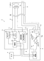
- FIG. 1 is a block diagram showing a configuration of an endoscope apparatus according to the first embodiment of the present invention.
- An endoscope apparatus 1 shown in FIG. 1 is inserted into a body cavity, and an electronic endoscope (hereinafter referred to as an endoscope) 2 for observing an observation site, and normal light and special light are applied to the endoscope 2.
- the light source device 3 to be supplied and the processor 5 that processes the image signal picked up by the endoscope 2 and displays the signal on the monitor 4 are configured.
- the endoscope 2 includes a solid-state imaging device (hereinafter, referred to as a CCD) 7 such as a CCD that is a solid-state imaging device provided at a distal end portion 2B of an insertion portion 2A that is inserted into a body cavity, and a front portion of the CCD 7 at the distal end portion 2B.
- a CCD solid-state imaging device
- An objective lens system 8 a light guide 9 for guiding observation illumination light to the distal end portion 2B of the insertion portion 2A, and an operation switch (not shown) provided in an operation portion for operating the endoscope 2
- a connector portion 10 for connecting to the light source device 3 and an electrical connector portion 11 for connecting to the processor 5.
- the endoscope apparatus 1 can perform normal light observation using normal light and special light observation using special light, here, narrow band imaging (NBI) using narrow band light.
- NBI narrow band imaging
- a plurality of light receiving side color filters 7 a necessary for forming an endoscopic image are regularly arranged on the front surface of a plurality of light receiving elements of the CCD 7.
- the light receiving side color filter 7a is a complementary color type color filter, and obtains an image signal of each color by using the difference in the amount of return light transmitted through the light receiving side color filter 7a of each color.
- the light-receiving side color filter 7a is not limited to the complementary color system, and is at least one necessary for forming an endoscopic image with special light receiving-side color filters such as R, G, and B, for example.
- Two special light receiving side color filters may be arranged with predetermined regularity to obtain image signals of each color, and the normal light receiving side color filter also serves as the special light receiving side color filter. It doesn't matter.
- Each of the light source device 3 and the processor 5 also has a plurality of observation modes. In particular, the light source device 3 and the processor 5 are compatible with both normal light and special light observation modes. Can perform normal light observation and special light observation.
- the processor 5 includes a timing generator 12 for controlling the overall timing of the endoscope apparatus 1, a CCD driver 13 for driving the CCD 7 of the endoscope 2, and an image processing unit 14 for processing an image signal from the CCD 7.
- the control unit 15 controls the entire endoscope apparatus 1 and input and display means (not shown) such as a keyboard and a front panel.
- the timing generator 12 generates an index signal that is a timing signal to be imaged by the CCD 7 and supplies the index signal to the control unit 15.
- the control unit 15 controls the CCD driver 13 based on this index signal to drive the CCD 7.
- the index signal is an imaging start timing signal for each imaging cycle S (see FIG. 2) of the CCD 7, that is, a reference signal synchronized with an exposure period by the CCD 7, and includes, for example, one field of an endoscope image and This is a vertical synchronization signal generated once per frame.
- the index signal is not limited to the vertical synchronization signal, and a similar reference signal generated by other means may be used.
- the image processing unit 14 processes the image signal from the CCD 7 and outputs it to the monitor 4.
- the image processing unit 14 is provided with a brightness detection unit 14a.
- the brightness detection unit 14 a determines the brightness of the endoscopic image based on the image signal in the previous imaging cycle, and outputs the detection result to the control unit 15.
- the control unit 15 controls the CCD driver 13 based on the index signal to drive the CCD 7. Further, the control unit 15 controls the signal processing by the image processing unit 14 to display the obtained endoscopic image on the monitor 4.
- control unit 15 communicates with an LED control unit 17 (to be described later) of the light source device 3 via the signal cable 6 to exchange various data.
- control unit 15 outputs the brightness detection result from the brightness detection unit 14 a and the index signal from the timing generator 12 to the LED control unit 17 of the light source device 3.
- the brightness detection result may be directly output from the image processing unit 14 to the LED control unit 17 without using the control unit 15.
- the timing generator 12, the CCD driver 13, the image processing unit 14, and the control unit 15 are configured separately. One configuration may be used.
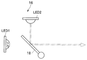
- the light source device 3 includes a light source unit 16 and an LED control unit 17 that controls the light source unit 16.
- the light source unit 16 includes a plurality of illumination units LED1 and LED2 having one or a plurality of light emitting elements, an optical filter 18, and a lens 19 for irradiating the end face of the light guide 9 with illumination light from the optical filter 18.
- the light emitting element is LED, it is not restricted to this, A laser diode, organic EL, etc. may be sufficient.
- the LED 1 is, for example, an LED that emits white light
- the LED 2 is, for example, an LED that emits light in violet (V) color. That is, the endoscope apparatus 1 of the present embodiment is provided with the two LEDs 1 and 2 as a plurality of illumination units in order to perform special light observation such as narrow-band light observation. Note that the plurality of illumination units are not limited to the two LEDs 1 and 2, and for example, three or more LEDs may be provided so as to obtain a necessary emission color.
- the optical filter 18 has an optical characteristic that converts white light from the LED 1 into green (G) color and irradiates the lens 19, and reflects violet light from the LED 2 to irradiate the lens 19.
- the endoscope apparatus 1 of the present embodiment has the two LEDs 1 as a plurality of illumination units in order to obtain green (G) light and violet light necessary for performing special light observation such as narrow-band light observation.
- the LED 2 and the optical filter 18 are provided.
- the optical filter 18 is configured to be rotatable so as to be retracted from the optical path of the light from the LED 1 with the shaft 18a as a fulcrum. That is, in the endoscope apparatus 1 in FIG. 1, the arrangement position of the optical filter 18 indicates a state in which special light observation such as narrow band light observation is performed.
- the control unit 15 of the processor 5 A control signal for executing the observation mode is output to the LED control unit 17 of the light source device 3.
- the LED control unit 17 that has received this control signal controls a drive unit (not shown) that applies a driving force to the optical filter 18 so that the optical filter 18 is retracted from the optical path of the LED 1 (broken line in FIG. 1). The position shown in FIG. Thereby, white light necessary for performing normal light observation is obtained by irradiating the lens 19 with white light only from the LED 1.
- the lens 19 irradiates the end surface of the light guide 9 with incident light. Thereby, the illumination light from the light source unit 16 is transmitted to the distal end portion 2B of the endoscope 2 by the light guide 9, and the subject is irradiated with the illumination light.
- the LED control unit 17 which is an illumination control unit, controls the lighting of the LEDs 1 and LED 2 of the optical unit 16 based on the brightness detection result by the brightness detection unit 14 a of the processor 5 and the index signal from the timing generator 12. . Further, the LED control unit 17 controls a driving unit (not shown) so that the optical filter 18 is disposed at a position corresponding to normal light observation or special light observation based on a control signal from the control unit 15.
- control of the light source unit 16 of the endoscope apparatus 1 has been described as being performed by the LED control unit 17, but the control unit 15 of the processor 5 and the LED control unit 17 of the light source device 3 are
- an FPGA Field ⁇ ⁇ ⁇ Programmable Gate Array
- the LED control unit 17 when performing normal light observation, does not turn on the LED 2 and uses the LED 1 based on an index signal that is an imaging start timing signal for each imaging cycle of the CCD 7.
- the driving time of the LED 1 is variably controlled in order to adjust the exposure amount within the imaging cycle.
- the LED control unit 17 stores standard brightness in one imaging cycle, and based on the difference between this brightness and the brightness detection result that is the brightness of the previous field or previous frame.
- the LED 1 lighting period is calculated and driven.
- the subject is irradiated with white light which is normal light
- the CCD 7 exposes the return light of the irradiated light as one imaging cycle.
- the CCD 7 performs photoelectric conversion based on the return light that has passed through the light-receiving side color filter 7a to obtain image signals of each color in one imaging cycle.
- the image signals of the respective colors are combined to obtain an endoscope image for normal light observation in one image period.
- the LED control unit 17 determines whether the LED 1 and the LED 2 are based on an index signal that is an imaging start timing signal for each imaging cycle of the CCD 7. In order to continuously drive the two LEDs 1 and LED2 within the imaging cycle and to adjust the exposure amount within the imaging cycle so that the driving times do not overlap each other, The driving time is variably controlled, and at least the first driving in the imaging cycle of the LED 2 driven second and later in the imaging cycle is driven based on the driving timing of the LED 1 driven before that. To control.
- the LED control unit 17 is abbreviated as the drive stop timing of the LED 1 that is driving at least the first drive in the imaging cycle of the LED 2 that is driven after the second in the imaging cycle. Control to drive simultaneously. That is, the endoscope apparatus 1 has a plurality of observation modes, and the plurality of LEDs are controlled to be turned on and off according to the observation mode designated or selected by the user.
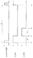
- FIG. 2 is a timing chart for explaining the operation of the endoscope apparatus of FIG. 1, FIG. 2 (a) is an index signal, FIG. 2 (b) is a drive signal of LED1, and FIG. 2 (c) is LED2. Drive signals are respectively shown.
- the “High” level indicates the on state of the signal, and the “Low” level indicates the off state of the signal.
- the endoscope apparatus 1 shown in FIG. 1 After the endoscope apparatus 1 shown in FIG. 1 is turned on, the insertion portion 2A is inserted into the body cavity, and special light observation using narrow band light is performed on the observation site in the body cavity. At this time, the endoscope apparatus 1 of the present embodiment performs lighting control of the light source unit 16 of the light source apparatus 3 at a timing as shown in FIG.
- the LED control unit 17 first determines the LED 1 and the LED 1 based on the brightness detection result within the imaging period S of the CCD 7 determined by the index signal that is the imaging start timing signal (within the period indicated between the time t0 and the time ts). Each lighting period T1, T2 of LED2 is calculated.
- the LED control unit 17 stores, for example, standard brightness in one imaging cycle, and is based on the difference between this brightness and the brightness detection result that is the brightness of the previous field or previous frame.
- the lighting period T1 of LED1 and the lighting period T2 of LED2 are calculated. That is, the LED control unit 17 calculates the driving time of each illumination unit based on the difference between the predetermined brightness in one imaging cycle and the field or frame brightness in the imaging cycle immediately before the imaging cycle. To do.
- the LED control unit 17 causes the LED 1 to emit light at the time to when the index signal shown in FIG. 2A becomes the “High” level (FIG. 2). (See (b)). Then, the white light emitted by the LED 1 is converted into green (G) light by the optical filter 18 and then incident on the end surface of the light guide 9 by the lens 19.
- the LED control unit 17 controls the LED 2 to be turned on at the same time as turning off the lighting of the LED 1 (FIGS. 2A and 2). b)).
- the control of the lighting timing of the LED 2 may be performed based on the lighting time of the LED 1 or based on turning off the LED 1.
- LED2 is turned on at the same time as LED1 is turned off. Then, at time t1, the violet light emitted from the LED 2 is reflected by the optical filter 18 and then enters the end surface of the light guide 9 by the lens 19. The LED 2 is lit during the calculated lighting period T2, that is, until time t2.
- the subject is sequentially irradiated with the special light green (G) light and violet light.
- the CCD 7 exposes the return light of the irradiation light within one exposure period within one imaging period.
- the CCD 7 photoelectrically converts the light that has passed through the light-receiving side color filter 7a to obtain image signals of each color in one imaging cycle. Then, the image signals of the respective colors are combined to obtain an endoscope image for special light observation in one imaging cycle.
- the LED 1 is turned off and the LED 2 is turned on at time t1 so as to be switched without a time lag.
- the present invention is not limited to this.
- the CCD driver 13 of the processor 5 A time lag may occur depending on the operation capability.
- the lighting timing of the LED 2 is controlled based on the lighting time T1 or the lighting timing t1 of the LED 1, but not limited to this, for example, as shown in FIG. 1, light emitted from the LED 1
- the light sensor 20 may detect the turn-off of the LED 1 and the lighting timing of the LED 2 may be controlled based on the detection result. That is, even if the timing of stopping the LED 1 is detected based on the detection result of the optical sensor that detects the light emitted from the LED 1 that has been driven before, the lighting timing of the LED 2 is controlled. good.
- the exposure period of the CCD 7 becomes the lighting period T1 + the lighting period T2, as shown in FIGS. 2B and 2C.
- the intervals between the exposure periods of the plurality of colors in the imaging cycle period S (see FIG. 2A) of the CCD 7 can be shortened.
- the CCD 7 In this imaging cycle period S (see FIG. 2A), the intervals between the lighting periods of the plurality of LEDs are short or almost absent, so that image blurring that occurs in the endoscopic image displayed on the monitor 4 is reduced. Can do.
- the green (G) color illumination light is converted by transmitting the white light from the LED 1 through the optical filter 18, and this conversion causes a loss of light amount. Therefore, in order to obtain bright green (G) illumination light, it is necessary to drive the LED 1 with high output.
- the plurality of illumination units are sequentially turned on within one imaging cycle so that the driving times of the plurality of LEDs overlap each other, thereby driving the LEDs rather than simultaneously driving the LEDs with high output. Therefore, a large load is not applied to the power source for making the power source large, and it is possible to prevent an increase in the size of the power source and a complicated circuit. Therefore, according to the first embodiment, it is possible to realize the endoscope apparatus 1 that can obtain a bright, high-quality endoscope image with a simple configuration, at a low cost.
- the plurality of illumination units are limited to the two LEDs 1 and 2 and are configured to switch between the normal light observation mode and the special light observation mode.
- each color light of R, G, and B is used.
- the LED control unit 17 performs lighting control so that LEDs of R, G, and B colors are sequentially turned on within one imaging cycle.
- it may be configured to perform normal light observation.
- the distal end portion 2B of the endoscope 2 is configured by providing three LEDs 16a to 16c that emit light of R, G, and B colors, Lighting control may be performed by the control unit 17. In this case, the same effect as that of the first embodiment can be obtained.
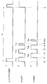
- FIG. 4 is a timing chart for explaining the operation of the endoscope apparatus according to the second embodiment of the present invention
- FIG. 5 is a timing chart showing a control example of the endoscope apparatus in the second modification. is there.
- the endoscope apparatus 1 of the present embodiment has the same configuration as that of the first embodiment, but the control method of the LED control unit 17 in the special light observation mode of the light source device 3 is different from that of the first embodiment. Different. That is, in the endoscope apparatus 1 of the present embodiment, the LED control unit 17 controls at least two of the plurality of illumination units to be driven a plurality of times within the imaging cycle period S.
- the LED control unit 17 equally divides and divides the lighting period T1 of the LED 1 and the lighting period T2 of the LED 2 that are calculated based on the brightness detection result in advance.
- the lighting periods T1a to T1g and the lighting periods T2a to T2g are obtained.
- the lighting period T1 obtained in the first embodiment is obtained. Further, when all the lighting periods T2a to T2g divided equally are added, the lighting period T2 (see FIG. 3) obtained in the first embodiment is obtained.
- the LED control unit 17 turns on the LED 1 at the time to when the index signal shown in FIG. 4A becomes the “High” level (see FIG. 4B). ).
- the LED control unit 17 turns off the LED 1 and turns off the LED 2 after the lighting period T1a of the LED 1 elapses, that is, at time t1. Control to light up.
- the LED control unit 17 performs control so that the LED 1 is turned on at the same time that the LED 2 is turned off at the time t2 after the lighting period T2a of the LED 2 has elapsed. Thereafter, the LED control unit 17 similarly controls the LED 1 and the LED 2 to be alternately lit so as to correspond to each lighting period until the lighting by the lighting period T1g and the lighting period T2g is completed. That is, the LED control unit 17 drives the plurality of LEDs a plurality of times so that the LEDs are alternately lit for the lighting time obtained by equally dividing the driving times of the plurality of LEDs.
- the endoscope apparatus 1 sets each lighting period of the total lighting time T1 of the LED 1 and the total lighting time T2 of the LED 2 within a predetermined number of times within an imaging cycle.
- the LED 1 and the LED lighting control may be performed so as to correspond to the divided lighting periods. That is, the LED control unit 17 drives the plurality of LEDs a plurality of times so that the two LEDs are alternately lit for a lighting time obtained by dividing each of the driving times of the two LEDs by a predetermined period.
- the LED control unit 17 divides the lighting period T1 of the LED 1 and the lighting period T2 of the LED 2 that are calculated based on the brightness detection result in advance by arbitrary values, The divided lighting periods T1a, T1b, T1c and the lighting periods T2a, T2b, T2c are obtained.
- the lighting periods T1a and T1b have the same value, and the remaining lighting period obtained by subtracting the lighting periods T1a and T1b from the lighting period T1 is set as the lighting period T1c.
- the lighting periods T2a and T2b are also set to the same value, and the remaining lighting period obtained by subtracting the lighting periods T2a and T2b from the lighting period T2 is set as the lighting period T2c.
- the lighting period T1 obtained in the first embodiment is obtained. Further, when all the lighting periods T2a, T2b, and T2c divided by an arbitrary value are added, the lighting period T2 obtained in the first embodiment (see FIG. 3) is obtained.
- the LED control unit 17 turns on the LED 1 at the time to when the index signal shown in FIG. 5A becomes “High” level (see FIG. 5B). ).
- the LED control unit 17 turns off the LED 1 and turns off the LED 2 after the lighting period T1a of the LED 1, e.g., at time t1. Control to light up.
- the LED control unit 17 controls the LED 1 to turn on at the same time as turning off the LED 2 after the lighting period T2a of the LED 2, that is, at time t2. Thereafter, the LED control unit 17 controls the LED 2 to be turned on at the same time as the LED 1 is turned off after the lighting period T1b of the LED 1 has elapsed, that is, at time t3.
- the LED control unit 17 controls to turn on the LED 1 at the same time as turning off the LED 2 after the lighting period T2b of the LED 2 has elapsed, that is, at time t4. Thereafter, the LED control unit 17 performs control so that the LED 1 is turned off in the remaining lighting period T2c shown between time t6 and t7 after the LED 1 is turned off at the time t5 after the lighting period T1c of the LED 1 elapses. To do.
- control of the light source unit 16 of the endoscope apparatus 1 has been described as being performed by the LED control unit 17, but the control unit 15 of the processor 5 is configured to perform the control. May be.
- control unit 15 of the processor 5 and the LED control unit 17 of the light source device 3 may be configured as one control unit so as to control the light source unit 16.
- the endoscope apparatus 1 of the present invention is configured by providing two LEDs 1 and LED2, but during observation, Even if any one of the LEDs fails, it is possible to secure illumination light necessary for removing the insertion portion 2A from the body cavity.
- Such a configuration is disclosed in FIGS.
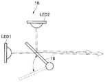
- FIG. 6 is a schematic diagram showing the configuration of the light source unit in the disclosed example 1
- FIG. 7 is a schematic diagram showing an operation state when the LED 1 in FIG. 6 fails.
- the light source unit 16 of the light source device 3 shown in FIG. 6 is substantially the same as that of the first embodiment. That is, the light source unit 16 converts white light from the LED 1 into green (G) color by the optical filter 18 arranged as shown in FIG. 6 when performing special light observation such as narrow-band light observation.
- the lens 19 is irradiated and the violet light from the LED 2 is reflected and irradiated to the lens 19. Thereby, green (G) color light and violet light necessary for special light observation are obtained.
- the light source unit 16 when performing normal light observation, is arranged so that the optical filter 18 is disposed at a position where the optical filter 18 is retracted from the optical path of the LED 1 (position indicated by a broken line in FIG. 6).
- the lens 19 is irradiated with white light. As a result, white light necessary for normal light observation is obtained.
- the optical filter 18 is arranged at a position as shown in FIG.
- the endoscope apparatus 1 of this example only the violet light used in at least narrow band light observation can be irradiated from the distal end portion 2B.
- the distal end portion 2B thereby, although it is only violet light, a to-be-photographed object can be irradiated from the front-end
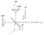
- FIG. 8 is a schematic diagram illustrating the configuration of the light source unit in the disclosure example 2
- FIG. 9 is a schematic diagram illustrating an operation state when the LED 1 of FIG. 8 fails.
- the light source unit 16A of the light source device 3 shown in FIG. 8 is substantially the same as the first disclosure example, but is different in that it is configured to obtain white light instead of violet light even when the LED 1 fails.
- the light source unit 16 ⁇ / b> A is provided with a fluorescent filter 30 that can move in an optical path of violet light from the LED 2 that reflects from the optical filter 18.
- the fluorescent filter 30 is disposed in the optical path of the violet light reflected from the optical filter 18 and converts the captured violet light into white light when the LED 1 fails. And has an optical characteristic to be emitted. That is, when performing normal light observation or special light observation, the fluorescent filter 30 is disposed at a position where it is retracted from the optical path of the LED 2 as shown in FIG.
- the fluorescent filter 30 can convert the captured violet light into white light and irradiate the lens 19. Therefore, since the white light can be irradiated from the tip portion 2B instead of the violet light in the disclosure example 1, the white light that is the normal light similar to the case of performing the normal light observation can be secured. Can be continued without interruption. As described above, according to the endoscope apparatus of the above-described embodiment, it is possible to obtain a bright, high-definition endoscope image with a simple configuration and at a low cost.
Abstract
An endoscopy device (1) according to one embodiment includes a CCD (7) and an LED control unit (17) (control unit (15)) for controlling an LED (1) and an LED (2). The LED control unit (17) sequentially drives the two LEDs (1), (2) during an imaging cycle (S) of the CCD (7) so that drive times of the LED (1) and the LED (2) do not overlap, on the basis of an imaging start time signal for every imaging cycle (S), and also variably controls the drive times of the LED (1) and LED (2) in order to adjust an amount of light exposure during the imaging cycle (S). The LED control unit (17) also controls at least the initial driving during the imaging cycle (S) of the LED (2), which is driven secondly or later during the imaging cycle (S), so as to be implemented on the basis of the drive timing of the LED (1), which is driven earlier.
Description
本発明は、観察部位に照射する照明光を出射する複数の照明部と、これら複数の照明部の駆動を制御する制御部とを有する内視鏡装置に関する。
The present invention relates to an endoscope apparatus that includes a plurality of illumination units that emit illumination light to irradiate an observation site and a control unit that controls driving of the plurality of illumination units.
内視鏡装置には、照明光を出射する照明部を有し、照明部からの出射光を観察部位へ照明光として照射し、被写体から反射された照明光の戻り光を、CCD(Charge Coupled Device)等の固体撮像素子で受光(露光)し光電変換することにより、被写体の画像に対応した画像信号を得る、所謂電子内視鏡装置が、一般的に知られている。
The endoscope apparatus includes an illumination unit that emits illumination light, irradiates the observation site with illumination light emitted from the illumination unit as illumination light, and returns the return light of the illumination light reflected from the subject to a CCD (Charge Coupled). 2. Description of the Related Art A so-called electronic endoscope apparatus that obtains an image signal corresponding to an image of a subject by receiving light (exposure) with a solid-state imaging device such as Device and performing photoelectric conversion is generally known.
この様な電子内視鏡装置において、所謂面順次式の内視鏡装置が一般的に知られている。面順次式の内視鏡装置は、固体撮像素子の受光素子の前面に受光側カラーフィルタを有さず、内視鏡画像の形成に必要となる複数色の照明光を観察部位へ順番に照射する。そして、照明光の照射毎に1つの撮像周期として固体撮像素子が露光し、被写体から反射された戻り光を固体撮像素子で光電変換し、各々の撮像周期毎に、所定の色の画像信号を得る。そして、各々の撮像周期毎に得られた各色の画像信号を合成処理することにより、1つの内視鏡画像を得ることができる。
In such an electronic endoscope apparatus, a so-called frame sequential endoscope apparatus is generally known. The field-sequential endoscope apparatus does not have a light-receiving side color filter in front of the light-receiving element of the solid-state image sensor, and sequentially irradiates the observation site with multiple colors of illumination light necessary for forming an endoscopic image. To do. Then, the solid-state imaging device is exposed as one imaging cycle for each illumination light irradiation, the return light reflected from the subject is photoelectrically converted by the solid-state imaging device, and an image signal of a predetermined color is generated for each imaging cycle. obtain. Then, one endoscopic image can be obtained by synthesizing the image signals of the respective colors obtained for each imaging cycle.
この様な面順次式の内視鏡装置には、内視鏡画像の形成に必要となる複数色の照明光を生成するための各色の照射側カラーフィルタを有するカラーホイールが例えば白色光を発する光源の前方に配置された光源装置を有し、このカラーホイールを回転駆動することにより、例えばR,G,B等の複数色の照明光を、ライトガイド等を介して順に内視鏡の挿入部の先端部から被写体に照射するものがある。
In such a field sequential endoscope apparatus, a color wheel having irradiation color filters for each color for generating a plurality of colors of illumination light necessary for forming an endoscope image emits white light, for example. Having a light source device arranged in front of the light source, and rotating the color wheel, for example, a plurality of colors of light such as R, G, and B are inserted into the endoscope sequentially through a light guide or the like. Some subjects irradiate the subject from the tip of the part.
このような構成の内視鏡装置は、カラーホイールの回転周期によってR,G,B等の各色の照明光の照射時間や照射周期(照射タイミング)が決まる。そして、この決められた照射周期における照射時間内で、固体撮像素子の露光時間を調整して各色の画像信号を得ることにより、適切な明るさの内視鏡画像を得ることができる。
In the endoscope apparatus having such a configuration, the irradiation time and the irradiation period (irradiation timing) of the illumination light of each color such as R, G, and B are determined by the rotation period of the color wheel. An endoscopic image with appropriate brightness can be obtained by adjusting the exposure time of the solid-state imaging device within the irradiation time in the determined irradiation cycle to obtain image signals of each color.
しかし、固体撮像素子の撮像周期は、各色の照明光の照射周期に合わせる必要があり、固体撮像素子の撮像周期は、カラーホイールの回転周期によって決まってしまうことになるので、例えば観察部位が心臓近傍等の動きのある部位の場合、被写体が動いたり、観察部位の動きに起因して固体撮像素子を内蔵した内視鏡の挿入部の先端部が動いてしまい、モニタに表示される内視鏡画像に色ズレや画像ブレが発生してしまう虞がある。
つまり、各色の照明光の照射周期が、カラーホイールの一定の回転周期によって決まっているため、各色の照明光の照射周期の間隔が長いと、固体撮像素子の撮像周期も長くなり、例えば、Rの照明光の露光時に対するGの照明光の露光時の、固体撮像素子が設けられた内視鏡の先端部と被写体との相対位置にずれが生じ、これにより、合成された1つの内視鏡画像におけるRとGとの画像にずれが生じ、内視鏡画像に所謂色ズレが生じる虞がある。また、R,G,Bの各照明光に応じた固体撮像素子の撮像周期や露光時間が長ければ長くなるほど、前記先端部の動きに起因して画像ブレも発生し易くなってしまう。 However, the imaging cycle of the solid-state imaging device needs to match the irradiation cycle of the illumination light of each color, and the imaging cycle of the solid-state imaging device is determined by the rotation cycle of the color wheel. In the case of a moving part such as the vicinity, the subject moves, or the distal end of the insertion part of the endoscope with a built-in solid-state imaging device moves due to the movement of the observation part. There is a risk of color misalignment and image blurring in the mirror image.
That is, since the irradiation period of the illumination light of each color is determined by a constant rotation period of the color wheel, if the interval of the irradiation period of the illumination light of each color is long, the imaging period of the solid-state image sensor also becomes long. The relative position between the distal end of the endoscope provided with the solid-state imaging device and the subject at the time of exposure of the G illumination light with respect to the exposure of the illumination light of FIG. There is a risk that the R and G images in the mirror image will be displaced, and so-called color misregistration may occur in the endoscopic image. In addition, as the imaging period and exposure time of the solid-state imaging device corresponding to each of the R, G, and B illumination lights become longer, image blurring is likely to occur due to the movement of the tip portion.
そこで、従来では、内視鏡画像に生じる色ズレや画像ブレを軽減するために、例えば、日本特開2007-29746号公報において提案された内視鏡装置がある。
Therefore, conventionally, for example, there is an endoscope apparatus proposed in Japanese Patent Application Laid-Open No. 2007-29746 in order to reduce color shift and image blur that occur in an endoscopic image.
日本特開2007-29746号公報に記載の内視鏡装置は、被写体からの戻り光が明るい又は暗いといった観察状況に応じて、R,G,Bの各色の照明光を発光する3つのLEDの各々の点灯時間および各々の色の画像信号を得るための固体撮像素子の露光時間を、標準的な時間と、短い時間と、逆に長い時間と、を選択出来るようにするとともに、この選択に応じて、固体撮像素子による撮像周期およびR,G,Bの各色のLEDの点灯周期(点灯タイミング)を、標準的な周期と、短い周期と、逆に長い周期と、に変えるように制御することにより、観察状況に応じて最適な撮像周期による観察画像が得られるようにして、内視鏡画像の色ズレや画像ブレを低減している。
前記日本特開2007-29746号公報に記載の内視鏡は、例えば、CCDの撮像周期と、R,G,Bの各色のLEDの点灯周期とを、所定のタイミング信号に基づいて、垂直転送パルスに同期させると同時にその周期を短くしたり、長くしたりするように、CCDの撮像周期及びLEDの点灯周期の変更制御を行う必要がある。 The endoscope apparatus described in Japanese Patent Application Laid-Open No. 2007-29746 has three LEDs that emit R, G, and B illumination lights according to an observation situation where the return light from the subject is bright or dark. It is possible to select a standard time, a short time, and conversely a long time as the exposure time of the solid-state imaging device for obtaining each lighting time and each color image signal. Accordingly, the imaging cycle by the solid-state imaging device and the lighting cycle (lighting timing) of each color LED of R, G, and B are controlled to be changed to a standard cycle, a short cycle, and conversely a long cycle. Thus, an observation image with an optimal imaging period is obtained according to the observation situation, and color shift and image blur of the endoscope image are reduced.
The endoscope described in Japanese Patent Laid-Open No. 2007-29746, for example, performs vertical transfer of the CCD imaging cycle and the R, G, B LED lighting cycle based on a predetermined timing signal. It is necessary to perform control to change the CCD imaging cycle and the LED lighting cycle so that the cycle is shortened or lengthened at the same time as synchronizing with the pulse.
しかしながら、このように、CCDの撮像周期及びLEDの点灯周期の変更制御を行うために、CCDを駆動させるタイミング信号のためのクロック周波数を変更することは容易ではなく、このような変更制御が可能な内視鏡装置を構築しようとしても、回路構成が複雑になってしまい、結果として、システム全体が高価になってしまう。
However, it is not easy to change the clock frequency for the timing signal for driving the CCD in order to change the CCD imaging cycle and the LED lighting cycle in this way, and such change control is possible. Even if an attempt is made to construct a simple endoscope apparatus, the circuit configuration becomes complicated, and as a result, the entire system becomes expensive.
また、日本特開2007-29746号公報に記載の内視鏡装置では、固体撮像素子の撮像周期を予め決められた複数の周期からしか選択することができず、観察状況に応じて撮像周期の細かい制御が行えない。また、予め決められた周期の種類を増やすと、回路構成が複雑になってしまい、結果として、システム全体が高価になってしまう。
Further, in the endoscope apparatus described in Japanese Patent Application Laid-Open No. 2007-29746, the imaging cycle of the solid-state imaging device can be selected only from a plurality of predetermined cycles, and the imaging cycle of the solid-state imaging device can be selected according to the observation situation. Fine control is not possible. Further, when the number of predetermined cycles is increased, the circuit configuration becomes complicated, and as a result, the entire system becomes expensive.
そこで、本発明は上記事情に鑑みてなされたもので、簡単な構成で、かつ安価で、明るく高品位な内視鏡画像を得ることのできる内視鏡装置を提供することを目的とする。
Therefore, the present invention has been made in view of the above circumstances, and an object of the present invention is to provide an endoscope apparatus that can obtain a bright, high-quality endoscopic image with a simple configuration and at a low cost.
本発明の一態様の内視鏡装置は、観察部位の観察画像を得る撮像部と、単数または複数の発光素子を有し、前記観察部位を照射する照明光を出射する複数の照明部と、前記複数の照明部の駆動を制御する照明制御部と、を有する内視鏡装置であって、各々の前記照明部により前記観察部位に照射される光は、異なる色の光であるとともに、前記照明制御部は、前記複数の照明部の駆動時間が互いに重ならないように、前記撮像部の撮像周期内で前記複数の照明部を順次駆動するように制御し、前記撮像周期内において、二番目以降に駆動する前記照明部の前記撮像周期内における少なくとも最初の駆動を、前記二番目以降に駆動する前記照明部よりも前に駆動している照明部の駆動タイミングを基準に駆動するように制御する。
An endoscope apparatus according to an aspect of the present invention includes an imaging unit that obtains an observation image of an observation site, a plurality of illumination units that have one or a plurality of light emitting elements, and emit illumination light that irradiates the observation site. An illumination control unit that controls driving of the plurality of illumination units, and the light irradiated to the observation site by each of the illumination units is light of a different color, and The illumination control unit controls the plurality of illumination units to be sequentially driven within the imaging cycle of the imaging unit so that the drive times of the plurality of illumination units do not overlap with each other. Control is performed so that at least the first drive of the illumination unit to be driven later in the imaging cycle is driven based on the drive timing of the illumination unit that is driven before the illumination unit to be driven second or later. To do.
以下、図面を参照しながら本発明の実施の形態について詳細に説明する。
Hereinafter, embodiments of the present invention will be described in detail with reference to the drawings.
(第1の実施形態)
図1は、本発明の第1の実施形態に係る内視鏡装置の構成を示すブロック図である。
図1に示す内視鏡装置1は、体腔内に挿入し、観察部位を観察する電子内視鏡(以下、内視鏡と称す)2と、この内視鏡2に通常光及び特殊光を供給する光源装置3と、内視鏡2により撮像された画像信号を信号処理してモニタ4に表示させるプロセッサ5と、を備えて構成される。 (First embodiment)
FIG. 1 is a block diagram showing a configuration of an endoscope apparatus according to the first embodiment of the present invention.
Anendoscope apparatus 1 shown in FIG. 1 is inserted into a body cavity, and an electronic endoscope (hereinafter referred to as an endoscope) 2 for observing an observation site, and normal light and special light are applied to the endoscope 2. The light source device 3 to be supplied and the processor 5 that processes the image signal picked up by the endoscope 2 and displays the signal on the monitor 4 are configured.
図1は、本発明の第1の実施形態に係る内視鏡装置の構成を示すブロック図である。
図1に示す内視鏡装置1は、体腔内に挿入し、観察部位を観察する電子内視鏡(以下、内視鏡と称す)2と、この内視鏡2に通常光及び特殊光を供給する光源装置3と、内視鏡2により撮像された画像信号を信号処理してモニタ4に表示させるプロセッサ5と、を備えて構成される。 (First embodiment)
FIG. 1 is a block diagram showing a configuration of an endoscope apparatus according to the first embodiment of the present invention.
An
内視鏡2は、体腔内に挿入する挿入部2Aの先端部2Bに設けられた固体撮像素子であるCCD等の固体撮像素子(以下、CCDと称す)7と、先端部2BのCCD7の前方に配設された対物レンズ系8と、挿入部2Aの先端部2Bへ観察照明光を導くライトガイド9と、内視鏡2の操作を行う操作部に設けられた操作スイッチ(図示せず)と、光源装置3に接続するためのコネクタ部10と、プロセッサ5に接続するための電気コネクタ部11と、を有する。
The endoscope 2 includes a solid-state imaging device (hereinafter, referred to as a CCD) 7 such as a CCD that is a solid-state imaging device provided at a distal end portion 2B of an insertion portion 2A that is inserted into a body cavity, and a front portion of the CCD 7 at the distal end portion 2B. An objective lens system 8, a light guide 9 for guiding observation illumination light to the distal end portion 2B of the insertion portion 2A, and an operation switch (not shown) provided in an operation portion for operating the endoscope 2 And a connector portion 10 for connecting to the light source device 3 and an electrical connector portion 11 for connecting to the processor 5.
内視鏡装置1は、通常光による通常光観察と、特殊光による特殊光観察、ここでは狭帯域光による狭帯域光観察(Narrow Band Imaging:NBI)とが可能なものである。
The endoscope apparatus 1 can perform normal light observation using normal light and special light observation using special light, here, narrow band imaging (NBI) using narrow band light.
内視鏡2は、内視鏡画像の形成に必要となる複数色の受光側カラーフィルタ7aをCCD7の複数の受光素子の前面に規則性を持ち配置している。
受光側カラーフィルタ7aは、補色系のカラーフィルタであり、各色の受光側カラーフィルタ7aを透過した戻り光の光量の差分を用いて、各色の画像信号を得る。 In theendoscope 2, a plurality of light receiving side color filters 7 a necessary for forming an endoscopic image are regularly arranged on the front surface of a plurality of light receiving elements of the CCD 7.
The light receivingside color filter 7a is a complementary color type color filter, and obtains an image signal of each color by using the difference in the amount of return light transmitted through the light receiving side color filter 7a of each color.
受光側カラーフィルタ7aは、補色系のカラーフィルタであり、各色の受光側カラーフィルタ7aを透過した戻り光の光量の差分を用いて、各色の画像信号を得る。 In the
The light receiving
なお、受光側カラーフィルタ7aは、補色系に限らず、例えばR,G,B等の通常光用受光側カラーフィルタと、特殊光での内視鏡画像を形成するために必要となる少なくとも1つの特殊光用受光側カラーフィルタと、を所定の規則性を持ち配設し、各色の画像信号を得てもよく、また、通常光用受光側カラーフィルタが特殊光用受光側カラーフィルタを兼ねても構わない。
光源装置3と、プロセッサ5も、それぞれ複数の観察モードを有し、特に、通常光と、特殊光の両方の観察モードに対応しており、内視鏡2と組み合わせて、内視鏡装置1は、通常光観察と特殊光観察を行うことができる。 The light-receivingside color filter 7a is not limited to the complementary color system, and is at least one necessary for forming an endoscopic image with special light receiving-side color filters such as R, G, and B, for example. Two special light receiving side color filters may be arranged with predetermined regularity to obtain image signals of each color, and the normal light receiving side color filter also serves as the special light receiving side color filter. It doesn't matter.
Each of the light source device 3 and the processor 5 also has a plurality of observation modes. In particular, the light source device 3 and the processor 5 are compatible with both normal light and special light observation modes. Can perform normal light observation and special light observation.
光源装置3と、プロセッサ5も、それぞれ複数の観察モードを有し、特に、通常光と、特殊光の両方の観察モードに対応しており、内視鏡2と組み合わせて、内視鏡装置1は、通常光観察と特殊光観察を行うことができる。 The light-receiving
Each of the light source device 3 and the processor 5 also has a plurality of observation modes. In particular, the light source device 3 and the processor 5 are compatible with both normal light and special light observation modes. Can perform normal light observation and special light observation.
プロセッサ5は、内視鏡装置1の全体のタイミングを制御するためのタイミングジェネレータ12と、内視鏡2のCCD7を駆動するCCDドライバ13と、CCD7からの画像信号を処理する画像処理部14と、内視鏡装置1全体を制御する制御部15と、キーボード、フロントパネル等の入力及び表示手段(図示せず)と、を有する。
The processor 5 includes a timing generator 12 for controlling the overall timing of the endoscope apparatus 1, a CCD driver 13 for driving the CCD 7 of the endoscope 2, and an image processing unit 14 for processing an image signal from the CCD 7. The control unit 15 controls the entire endoscope apparatus 1 and input and display means (not shown) such as a keyboard and a front panel.
タイミングジェネレータ12は、CCD7により撮像するタイミング信号であるインデックス信号を生成して制御部15に供給し、制御部15は、このインデックス信号に基づき、CCDドライバ13を制御してCCD7を駆動させる。
なお、インデックス信号は、CCD7の撮像周期S(図2参照)毎の撮像開始タイミング信号、すなわち、CCD7による露光期間に同期している基準信号であって、例えば、内視鏡画像の1フィールド及び1フレームに1回の周期で発生する垂直同期信号である。勿論、インデックス信号は、前記垂直同期信号に限定されるものではなく、他の手段で生成される同様な基準信号を用いても良い。
画像処理部14は、CCD7からの画像信号を処理してモニタ4に出力する。これにより、内視鏡画像はモニタ4に表示される。
また、画像処理部14には、明るさ検知部14aが設けられている。この明るさ検知部14aは、以前の撮像周期における画像信号を基に、内視鏡画像の明るさを判定し、その検知結果を制御部15に出力する。 Thetiming generator 12 generates an index signal that is a timing signal to be imaged by the CCD 7 and supplies the index signal to the control unit 15. The control unit 15 controls the CCD driver 13 based on this index signal to drive the CCD 7.
The index signal is an imaging start timing signal for each imaging cycle S (see FIG. 2) of theCCD 7, that is, a reference signal synchronized with an exposure period by the CCD 7, and includes, for example, one field of an endoscope image and This is a vertical synchronization signal generated once per frame. Of course, the index signal is not limited to the vertical synchronization signal, and a similar reference signal generated by other means may be used.
Theimage processing unit 14 processes the image signal from the CCD 7 and outputs it to the monitor 4. Thereby, the endoscopic image is displayed on the monitor 4.
Theimage processing unit 14 is provided with a brightness detection unit 14a. The brightness detection unit 14 a determines the brightness of the endoscopic image based on the image signal in the previous imaging cycle, and outputs the detection result to the control unit 15.
なお、インデックス信号は、CCD7の撮像周期S(図2参照)毎の撮像開始タイミング信号、すなわち、CCD7による露光期間に同期している基準信号であって、例えば、内視鏡画像の1フィールド及び1フレームに1回の周期で発生する垂直同期信号である。勿論、インデックス信号は、前記垂直同期信号に限定されるものではなく、他の手段で生成される同様な基準信号を用いても良い。
画像処理部14は、CCD7からの画像信号を処理してモニタ4に出力する。これにより、内視鏡画像はモニタ4に表示される。
また、画像処理部14には、明るさ検知部14aが設けられている。この明るさ検知部14aは、以前の撮像周期における画像信号を基に、内視鏡画像の明るさを判定し、その検知結果を制御部15に出力する。 The
The index signal is an imaging start timing signal for each imaging cycle S (see FIG. 2) of the
The
The
制御部15は、インデックス信号に基づいてCCDドライバ13を制御してCCD7を駆動させる。また、制御部15は、画像処理部14による信号処理を制御して、得られた内視鏡画像をモニタ4に表示させる。
The control unit 15 controls the CCD driver 13 based on the index signal to drive the CCD 7. Further, the control unit 15 controls the signal processing by the image processing unit 14 to display the obtained endoscopic image on the monitor 4.
また、制御部15は、信号ケーブル6を介して光源装置3の後述するLED制御部17との間で通信を行い、各種データのやり取りを行っている。
本実施形態において、制御部15は、明るさ検知部14aからの明るさ検知結果と、タイミングジェネレータ12からのインデックス信号とを、光源装置3のLED制御部17に出力する。
なお、明るさの検知結果は、制御部15を介さず、画像処理部14からLED制御部17へ直接出力されてもよい。 Further, thecontrol unit 15 communicates with an LED control unit 17 (to be described later) of the light source device 3 via the signal cable 6 to exchange various data.
In the present embodiment, thecontrol unit 15 outputs the brightness detection result from the brightness detection unit 14 a and the index signal from the timing generator 12 to the LED control unit 17 of the light source device 3.
The brightness detection result may be directly output from theimage processing unit 14 to the LED control unit 17 without using the control unit 15.
本実施形態において、制御部15は、明るさ検知部14aからの明るさ検知結果と、タイミングジェネレータ12からのインデックス信号とを、光源装置3のLED制御部17に出力する。
なお、明るさの検知結果は、制御部15を介さず、画像処理部14からLED制御部17へ直接出力されてもよい。 Further, the
In the present embodiment, the
The brightness detection result may be directly output from the
また、本実施形態においては、タイミングジェネレータ12とCCDドライバ13と画像処理部14と制御部15とを、別々の構成としているが、例えばFPGA(Field Programmable Gate Array)等により、一部または全てを1つの構成としても良い。
In the present embodiment, the timing generator 12, the CCD driver 13, the image processing unit 14, and the control unit 15 are configured separately. One configuration may be used.
光源装置3は、光源ユニット16と、この光源ユニット16を制御するLED制御部17と、を有して構成される。
光源ユニット16は、単数または複数の発光素子を有する複数の照明部であるLED1、LED2と、光学フィルタ18と、光学フィルタ18からの照明光をライトガイド9の端面に照射するためのレンズ19と、を有する。
なお、本実施形態では、発光素子をLEDとしているが、これに限らず、レーザダイオードや有機EL等でもよい。 The light source device 3 includes alight source unit 16 and an LED control unit 17 that controls the light source unit 16.
Thelight source unit 16 includes a plurality of illumination units LED1 and LED2 having one or a plurality of light emitting elements, an optical filter 18, and a lens 19 for irradiating the end face of the light guide 9 with illumination light from the optical filter 18. Have.
In addition, in this embodiment, although the light emitting element is LED, it is not restricted to this, A laser diode, organic EL, etc. may be sufficient.
光源ユニット16は、単数または複数の発光素子を有する複数の照明部であるLED1、LED2と、光学フィルタ18と、光学フィルタ18からの照明光をライトガイド9の端面に照射するためのレンズ19と、を有する。
なお、本実施形態では、発光素子をLEDとしているが、これに限らず、レーザダイオードや有機EL等でもよい。 The light source device 3 includes a
The
In addition, in this embodiment, although the light emitting element is LED, it is not restricted to this, A laser diode, organic EL, etc. may be sufficient.
LED1は、例えば、白色に発光するLEDであり、LED2は、例えば、バイオレット(V)色に発光するLEDである。すなわち、本実施形態の内視鏡装置1は、狭帯域光観察などの特殊光観察を行うために、複数の照明部として前記2つのLED1、LED2が設けられている。
なお、複数の照明部は、前記2つのLED1、LED2に限定されるものではなく、例えば、必要な発光色が得られるように3つ以上のLEDを設けて構成しても良い。 TheLED 1 is, for example, an LED that emits white light, and the LED 2 is, for example, an LED that emits light in violet (V) color. That is, the endoscope apparatus 1 of the present embodiment is provided with the two LEDs 1 and 2 as a plurality of illumination units in order to perform special light observation such as narrow-band light observation.
Note that the plurality of illumination units are not limited to the two LEDs 1 and 2, and for example, three or more LEDs may be provided so as to obtain a necessary emission color.
なお、複数の照明部は、前記2つのLED1、LED2に限定されるものではなく、例えば、必要な発光色が得られるように3つ以上のLEDを設けて構成しても良い。 The
Note that the plurality of illumination units are not limited to the two
光学フィルタ18は、LED1からの白色光を緑(G)色に変換してレンズ19へと照射するとともに、LED2からのバイオレット光を反射してレンズ19へと照射する光学特性を有する。
The optical filter 18 has an optical characteristic that converts white light from the LED 1 into green (G) color and irradiates the lens 19, and reflects violet light from the LED 2 to irradiate the lens 19.
すなわち、本実施形態の内視鏡装置1は、狭帯域光観察などの特殊光観察を行うのに必要な緑(G)色光とバイオレット光を得るために、複数の照明部として前記2つのLED1、LED2と光学フィルタ18が設けられている。
That is, the endoscope apparatus 1 of the present embodiment has the two LEDs 1 as a plurality of illumination units in order to obtain green (G) light and violet light necessary for performing special light observation such as narrow-band light observation. The LED 2 and the optical filter 18 are provided.
また、この光学フィルタ18は、軸18aを支点として、LED1からの光の光路中から待避するように回動可能に構成されている。
つまり、図1中の内視鏡装置1において、光学フィルタ18の配置位置は、狭帯域光観察などの特殊光観察を行う状態を示している。
一方、白色光の通常光による通常光観察を行う場合には、内視鏡2の図示しない操作部による操作によって、通常光観察モードに切り替えたとすると、プロセッサ5の制御部15は、この通常光観察モード実行のための制御信号を光源装置3のLED制御部17に出力する。そしてこの制御信号を受信したLED制御部17は、光学フィルタ18に駆動力を与える図示しない駆動部を制御することにより、光学フィルタ18が、LED1の光路中から待避する位置(図1中の破線に示す位置)に配置される。これにより、LED1のみからの白色光がレンズ19へと照射されることにより、通常光観察を行うのに必要な白色光を得ている。 Further, theoptical filter 18 is configured to be rotatable so as to be retracted from the optical path of the light from the LED 1 with the shaft 18a as a fulcrum.
That is, in theendoscope apparatus 1 in FIG. 1, the arrangement position of the optical filter 18 indicates a state in which special light observation such as narrow band light observation is performed.
On the other hand, when performing normal light observation using normal light of white light, if the normal light observation mode is switched by an operation by an operation unit (not shown) of theendoscope 2, the control unit 15 of the processor 5 A control signal for executing the observation mode is output to the LED control unit 17 of the light source device 3. The LED control unit 17 that has received this control signal controls a drive unit (not shown) that applies a driving force to the optical filter 18 so that the optical filter 18 is retracted from the optical path of the LED 1 (broken line in FIG. 1). The position shown in FIG. Thereby, white light necessary for performing normal light observation is obtained by irradiating the lens 19 with white light only from the LED 1.
つまり、図1中の内視鏡装置1において、光学フィルタ18の配置位置は、狭帯域光観察などの特殊光観察を行う状態を示している。
一方、白色光の通常光による通常光観察を行う場合には、内視鏡2の図示しない操作部による操作によって、通常光観察モードに切り替えたとすると、プロセッサ5の制御部15は、この通常光観察モード実行のための制御信号を光源装置3のLED制御部17に出力する。そしてこの制御信号を受信したLED制御部17は、光学フィルタ18に駆動力を与える図示しない駆動部を制御することにより、光学フィルタ18が、LED1の光路中から待避する位置(図1中の破線に示す位置)に配置される。これにより、LED1のみからの白色光がレンズ19へと照射されることにより、通常光観察を行うのに必要な白色光を得ている。 Further, the
That is, in the
On the other hand, when performing normal light observation using normal light of white light, if the normal light observation mode is switched by an operation by an operation unit (not shown) of the
レンズ19は、入射光をライトガイド9の端面に照射する。これにより、光源ユニット16からの照明光は、ライトガイド9により内視鏡2の先端部2Bへと伝達され、照明光が被写体に照射される。
The lens 19 irradiates the end surface of the light guide 9 with incident light. Thereby, the illumination light from the light source unit 16 is transmitted to the distal end portion 2B of the endoscope 2 by the light guide 9, and the subject is irradiated with the illumination light.
照明制御部であるLED制御部17は、プロセッサ5の明るさ検知部14aによる明るさ検知結果と、タイミングジェネレータ12からのインデックス信号とに基づいて、光学ユニット16のLED1、LED2の点灯制御を行う。また、LED制御部17は、前記制御部15からの制御信号に基づいて、光学フィルタ18が通常光観察又は特殊光観察に応じた位置に配置されるように図示しない駆動部を制御する。
The LED control unit 17, which is an illumination control unit, controls the lighting of the LEDs 1 and LED 2 of the optical unit 16 based on the brightness detection result by the brightness detection unit 14 a of the processor 5 and the index signal from the timing generator 12. . Further, the LED control unit 17 controls a driving unit (not shown) so that the optical filter 18 is disposed at a position corresponding to normal light observation or special light observation based on a control signal from the control unit 15.
なお、本実施形態では、内視鏡装置1の光源ユニット16の制御は、LED制御部17によって行われるように説明したが、プロセッサ5の制御部15と光源装置3のLED制御部17は、例えばFPGA(Field Programmable Gate Array)等により構成しても良い。
In the present embodiment, the control of the light source unit 16 of the endoscope apparatus 1 has been described as being performed by the LED control unit 17, but the control unit 15 of the processor 5 and the LED control unit 17 of the light source device 3 are For example, an FPGA (Field に よ り Programmable Gate Array) may be used.
本実施形態の内視鏡装置1において、通常光観察を行う際は、LED制御部17は、LED2を点灯させず、CCD7の撮像周期ごとの撮像開始タイミング信号であるインデックス信号を基に、LED1の駆動を行うとともに、前記撮像周期内の露光量を調整するために、LED1の駆動時間を可変に制御する。
In the endoscope apparatus 1 of the present embodiment, when performing normal light observation, the LED control unit 17 does not turn on the LED 2 and uses the LED 1 based on an index signal that is an imaging start timing signal for each imaging cycle of the CCD 7. In addition, the driving time of the LED 1 is variably controlled in order to adjust the exposure amount within the imaging cycle.
すなわち、LED制御部17は、例えば、1つの撮像周期における標準的な明るさを記憶しており、この明るさと、前フィールドまたは前フレームの明るさである明るさ検知結果との差に基づいて、LED1の点灯期間を算出し駆動させる。
That is, for example, the LED control unit 17 stores standard brightness in one imaging cycle, and based on the difference between this brightness and the brightness detection result that is the brightness of the previous field or previous frame. The LED 1 lighting period is calculated and driven.
これにより、被写体に通常光である白色光が照射され、その照射光の戻り光をCCD7が1つの撮像周期として露光する。そして、CCD7は、受光側カラーフィルタ7aを通過した戻り光を基に光電変換し、1つの撮像周期における各色の画像信号を得る。そして各色の画像信号を合成し、1つの画像周期における通常光観察の内視鏡画像を得る。
Thereby, the subject is irradiated with white light which is normal light, and the CCD 7 exposes the return light of the irradiated light as one imaging cycle. Then, the CCD 7 performs photoelectric conversion based on the return light that has passed through the light-receiving side color filter 7a to obtain image signals of each color in one imaging cycle. Then, the image signals of the respective colors are combined to obtain an endoscope image for normal light observation in one image period.
次に、本実施形態の内視鏡装置1において、特殊光観察を行う際は、LED制御部17は、CCD7の撮像周期ごとの撮像開始タイミング信号であるインデックス信号を基に、LED1とLED2の駆動時間が互いに重ならないように、かつ前記撮像周期内で2つのLED1とLED2の駆動を連続して順次行うとともに、前記撮像周期内の露光量を調整するために、前記2つのLED1、LED2の駆動時間を可変に制御し、前記撮像周期内において、二番目以降に駆動するLED2の前記撮像周期内における少なくとも最初の駆動を、その前に駆動しているLED1の駆動タイミングを基準に駆動させるように制御する。
Next, in the endoscope apparatus 1 of the present embodiment, when performing special light observation, the LED control unit 17 determines whether the LED 1 and the LED 2 are based on an index signal that is an imaging start timing signal for each imaging cycle of the CCD 7. In order to continuously drive the two LEDs 1 and LED2 within the imaging cycle and to adjust the exposure amount within the imaging cycle so that the driving times do not overlap each other, The driving time is variably controlled, and at least the first driving in the imaging cycle of the LED 2 driven second and later in the imaging cycle is driven based on the driving timing of the LED 1 driven before that. To control.
この場合、LED制御部17は、前記撮像周期内において、前記二番以降に駆動するLED2の、前記撮像周期内における少なくとも最初の駆動を、その前に駆動しているLED1の駆動停止タイミングと略同時に駆動させるように制御する。
すなわち、内視鏡装置1は、複数の観察モードを有し、複数のLEDは、ユーザにより指定あるいは選択された観察モードに応じて、各LEDの点灯と非点灯が制御される。 In this case, theLED control unit 17 is abbreviated as the drive stop timing of the LED 1 that is driving at least the first drive in the imaging cycle of the LED 2 that is driven after the second in the imaging cycle. Control to drive simultaneously.
That is, theendoscope apparatus 1 has a plurality of observation modes, and the plurality of LEDs are controlled to be turned on and off according to the observation mode designated or selected by the user.
すなわち、内視鏡装置1は、複数の観察モードを有し、複数のLEDは、ユーザにより指定あるいは選択された観察モードに応じて、各LEDの点灯と非点灯が制御される。 In this case, the
That is, the
このようなLED制御部17によるLED1、LED2の点灯制御例について、図1及び図2を用いて説明する。
図2は、図1の内視鏡装置の作用を説明するためのタイミングチャートであり、図2(a)はインデックス信号、図2(b)はLED1の駆動信号、図2(c)はLED2の駆動信号をそれぞれ示している。なお、図2中“High”レベルは信号のオン状態を示し、“Low”レベルは信号のオフ状態を示す。 An example of lighting control of the LEDs 1 and 2 by the LED control unit 17 will be described with reference to FIGS. 1 and 2.
2 is a timing chart for explaining the operation of the endoscope apparatus of FIG. 1, FIG. 2 (a) is an index signal, FIG. 2 (b) is a drive signal of LED1, and FIG. 2 (c) is LED2. Drive signals are respectively shown. In FIG. 2, the “High” level indicates the on state of the signal, and the “Low” level indicates the off state of the signal.
図2は、図1の内視鏡装置の作用を説明するためのタイミングチャートであり、図2(a)はインデックス信号、図2(b)はLED1の駆動信号、図2(c)はLED2の駆動信号をそれぞれ示している。なお、図2中“High”レベルは信号のオン状態を示し、“Low”レベルは信号のオフ状態を示す。 An example of lighting control of the
2 is a timing chart for explaining the operation of the endoscope apparatus of FIG. 1, FIG. 2 (a) is an index signal, FIG. 2 (b) is a drive signal of LED1, and FIG. 2 (c) is LED2. Drive signals are respectively shown. In FIG. 2, the “High” level indicates the on state of the signal, and the “Low” level indicates the off state of the signal.
いま、図1に示す内視鏡装置1の電源投入後、挿入部2Aを体腔内に挿入し、体腔内の観察部位の、狭帯域光による特殊光観察を行うものとする。
このとき、本実施形態の内視鏡装置1は、図2に示すようなタイミングで、光源装置3の光源ユニット16の点灯制御を行う。 Now, after theendoscope apparatus 1 shown in FIG. 1 is turned on, the insertion portion 2A is inserted into the body cavity, and special light observation using narrow band light is performed on the observation site in the body cavity.
At this time, theendoscope apparatus 1 of the present embodiment performs lighting control of the light source unit 16 of the light source apparatus 3 at a timing as shown in FIG.
このとき、本実施形態の内視鏡装置1は、図2に示すようなタイミングで、光源装置3の光源ユニット16の点灯制御を行う。 Now, after the
At this time, the
すなわち、プロセッサ5のタイミングジェネレータ12から図2(a)に示すようなタイミングのインデックス信号と、明るさ検知部14aからの明るさ検知結果とが光源装置3のLED制御部17に供給されると、LED制御部17は、まず、撮像開始タイミング信号であるインデックス信号によって決まるCCD7の撮像周期S内(時刻t0~時刻tsの間の示す期間内)において、明るさ検知結果に基づき、LED1、及びLED2の各点灯期間T1、T2を算出する。
That is, when the index signal of the timing as shown in FIG. 2A and the brightness detection result from the brightness detection unit 14a are supplied from the timing generator 12 of the processor 5 to the LED control unit 17 of the light source device 3. The LED control unit 17 first determines the LED 1 and the LED 1 based on the brightness detection result within the imaging period S of the CCD 7 determined by the index signal that is the imaging start timing signal (within the period indicated between the time t0 and the time ts). Each lighting period T1, T2 of LED2 is calculated.
この場合、LED制御部17は、例えば、1つの撮像周期における標準的な明るさを記憶しており、この明るさと、前フィールドまたは前フレームの明るさである明るさ検知結果との差に基づいて、LED1の点灯期間T1と、LED2の点灯期間T2とを算出する。すなわち、LED制御部17は、1つの撮像周期における所定の明るさと、当該撮像周期よりも一つ前の撮像周期におけるフィールド又はフレームの明るさとの差に基づいて、各照明部の駆動時間を算出する。
In this case, the LED control unit 17 stores, for example, standard brightness in one imaging cycle, and is based on the difference between this brightness and the brightness detection result that is the brightness of the previous field or previous frame. Thus, the lighting period T1 of LED1 and the lighting period T2 of LED2 are calculated. That is, the LED control unit 17 calculates the driving time of each illumination unit based on the difference between the predetermined brightness in one imaging cycle and the field or frame brightness in the imaging cycle immediately before the imaging cycle. To do.
そして、各LED1、2の点灯期間T1、T2を決定すると、LED制御部17は、図2(a)に示すインデックス信号が“High”レベルになった時刻toにおいて、LED1を発光させる(図2(b)参照)。すると、LED1により発光した白色光は、光学フィルタ18により緑(G)色光に変換された後、レンズ19によりライトガイド9の端面に入射される。
When the lighting periods T1 and T2 of the LEDs 1 and 2 are determined, the LED control unit 17 causes the LED 1 to emit light at the time to when the index signal shown in FIG. 2A becomes the “High” level (FIG. 2). (See (b)). Then, the white light emitted by the LED 1 is converted into green (G) light by the optical filter 18 and then incident on the end surface of the light guide 9 by the lens 19.
その後、LED1の点灯期間T1の経過後、即ち、時刻t1において、LED制御部17は、LED1の点灯を消灯させると同時に、LED2を点灯させるように制御する(図2(a)、図2(b)参照)。このLED2の点灯タイミングの制御は、LED1の点灯時間を基準として行っても、LED1を消灯させることを基準として行っても良い。
Thereafter, after the lighting period T1 of the LED 1 elapses, that is, at the time t1, the LED control unit 17 controls the LED 2 to be turned on at the same time as turning off the lighting of the LED 1 (FIGS. 2A and 2). b)). The control of the lighting timing of the LED 2 may be performed based on the lighting time of the LED 1 or based on turning off the LED 1.
すなわち、LED1の点灯許可期間内(時刻t0~時刻ts)であっても、LED1の消灯と同時に、LED2が点灯することになる。
すると、時刻t1において、LED2により出射されたバイオレット光は、光学フィルタ18により反射された後、レンズ19によりライトガイド9の端面に入射される。このLED2の点灯は、算出された点灯期間T2の間、即ち、時刻t2まで行われることになる。 That is, even within the lighting permission period of LED1 (time t0 to time ts), LED2 is turned on at the same time as LED1 is turned off.
Then, at time t1, the violet light emitted from theLED 2 is reflected by the optical filter 18 and then enters the end surface of the light guide 9 by the lens 19. The LED 2 is lit during the calculated lighting period T2, that is, until time t2.
すると、時刻t1において、LED2により出射されたバイオレット光は、光学フィルタ18により反射された後、レンズ19によりライトガイド9の端面に入射される。このLED2の点灯は、算出された点灯期間T2の間、即ち、時刻t2まで行われることになる。 That is, even within the lighting permission period of LED1 (time t0 to time ts), LED2 is turned on at the same time as LED1 is turned off.
Then, at time t1, the violet light emitted from the
これにより、CCD7の1つの撮像周期内において、被写体に特殊光である緑(G)色光とバイオレット光とが順次照射される。その照射光の戻り光をCCD7が1つの撮像周期内で1回の露光期間内で露光する。CCD7は、受光側カラーフィルタ7aを通過した光を光電変換し、1つの撮像周期における各色の画像信号を得る。そして各色の画像信号を合成し、1つの撮像周期における特殊光観察の内視鏡画像を得る。
Thus, within one imaging period of the CCD 7, the subject is sequentially irradiated with the special light green (G) light and violet light. The CCD 7 exposes the return light of the irradiation light within one exposure period within one imaging period. The CCD 7 photoelectrically converts the light that has passed through the light-receiving side color filter 7a to obtain image signals of each color in one imaging cycle. Then, the image signals of the respective colors are combined to obtain an endoscope image for special light observation in one imaging cycle.
なお、本実施形態では、LED1の消灯とLED2の点灯は、時刻t1において、タイムラグがない状態で切り替わるように説明したが、これに限定されるものではなく、例えば、プロセッサ5のCCDドライバ13の動作能力に応じてタイムラグが生じても良い。但し、内視鏡画像の色ズレや画像ブレの軽減を考慮すると、極力タイムラグの発生を無くすように構成することが望ましい。
In the present embodiment, the LED 1 is turned off and the LED 2 is turned on at time t1 so as to be switched without a time lag. However, the present invention is not limited to this. For example, the CCD driver 13 of the processor 5 A time lag may occur depending on the operation capability. However, in consideration of reduction of color shift and image blur of the endoscopic image, it is desirable to configure so as to eliminate the time lag as much as possible.
また、本実施形態では、LED2の点灯タイミングを、LED1の点灯時間T1または消灯タイミングt1を基準とし制御しているが、これに限らず、例えば図1にあるように、LED1から出射される光を検知する光センサ20により、LED1の消灯を検知し、この検知結果を基に、LED2の点灯タイミングを制御しても良い。すなわち、LED1の停止のタイミングが、その前に駆動しているLED1から出射される光を検知する光センサの検知結果に基づいて、検知されるようにして、LED2の点灯タイミングを制御しても良い。
Further, in this embodiment, the lighting timing of the LED 2 is controlled based on the lighting time T1 or the lighting timing t1 of the LED 1, but not limited to this, for example, as shown in FIG. 1, light emitted from the LED 1 The light sensor 20 may detect the turn-off of the LED 1 and the lighting timing of the LED 2 may be controlled based on the detection result. That is, even if the timing of stopping the LED 1 is detected based on the detection result of the optical sensor that detects the light emitted from the LED 1 that has been driven before, the lighting timing of the LED 2 is controlled. good.
従って、このようなLED制御部17のLED1、L2D2の点灯制御を行うことにより、図2(b)及び図2(c)に示すように、CCD7の露光期間は、点灯期間T1+点灯期間T2となり、CCD7の撮像周期期間S(図2(a)参照)内における複数の色の露光期間の間隔を短くすることができる。
Therefore, by performing the lighting control of the LEDs 1 and L2D2 of the LED control unit 17, the exposure period of the CCD 7 becomes the lighting period T1 + the lighting period T2, as shown in FIGS. 2B and 2C. The intervals between the exposure periods of the plurality of colors in the imaging cycle period S (see FIG. 2A) of the CCD 7 can be shortened.
このため、特に、動きが速い心臓に近い部位の臓器等の観察部位を観察している際に、その観察部位の動きに起因してCCD7を内蔵した先端部2Bが動いてしまっても、CCD7の撮像周期期間S(図2(a)参照)内における複数のLEDの点灯期間の間隔が短く、もしくはほとんど無いので、モニタ4に表示される内視鏡画像に発生する画像ブレを軽減することができる。
For this reason, especially when observing an observation site such as an organ near the heart that moves fast, even if the tip 2B incorporating the CCD 7 moves due to the movement of the observation site, the CCD 7 In this imaging cycle period S (see FIG. 2A), the intervals between the lighting periods of the plurality of LEDs are short or almost absent, so that image blurring that occurs in the endoscopic image displayed on the monitor 4 is reduced. Can do.
また、CCD7の撮像周期期間S(図2(a)参照)内において、LED1の消灯とLED2の点灯との間のタイムラグがなく、タイムラグが生じたとしても短い時間にすることができるので、特に、動きが速い心臓に近い部位の臓器等の観察部位を観察している際に、その観察部位の動きに起因してCCD7を内蔵した先端部2Bが動いてしまっても、モニタ4に表示される内視鏡画像に発生する色ズレを軽減することができる。
Further, there is no time lag between the turn-off of the LED 1 and the turn-on of the LED 2 within the imaging cycle period S (see FIG. 2A) of the CCD 7, and even if a time lag occurs, it can be a short time. When observing an observation site such as an organ near the fast-moving heart, even if the tip 2B incorporating the CCD 7 moves due to the movement of the observation site, it is displayed on the monitor 4. The color shift that occurs in the endoscopic image can be reduced.
ところで、特殊光観察モードにおいて、緑(G)色の照明光は、LED1かたの白色光を光学フィルタ18を透過させ変換しており、この変換により光量のロスが生じる。よって、明るい緑(G)色の照明光を得るためには、LED1を高出力で駆動させる必要がある。本実施形態においては、複数のLEDの駆動時間が互いに重ならいように、1つの撮像周期内で前記複数の照明部を順次点灯させることにより、LEDを同時に高出力で駆動させるより、LEDを駆動させるための電源に大きな負荷がかからず、電源の大型化や回路の複雑化を防ぐことができる。
従って、第1の実施形態によれば、簡単な構成で、かつ安価で、明るく高品位な内視鏡画像を得ることのできる内視鏡装置1を実現することができる。 By the way, in the special light observation mode, the green (G) color illumination light is converted by transmitting the white light from theLED 1 through the optical filter 18, and this conversion causes a loss of light amount. Therefore, in order to obtain bright green (G) illumination light, it is necessary to drive the LED 1 with high output. In this embodiment, the plurality of illumination units are sequentially turned on within one imaging cycle so that the driving times of the plurality of LEDs overlap each other, thereby driving the LEDs rather than simultaneously driving the LEDs with high output. Therefore, a large load is not applied to the power source for making the power source large, and it is possible to prevent an increase in the size of the power source and a complicated circuit.
Therefore, according to the first embodiment, it is possible to realize theendoscope apparatus 1 that can obtain a bright, high-quality endoscope image with a simple configuration, at a low cost.
従って、第1の実施形態によれば、簡単な構成で、かつ安価で、明るく高品位な内視鏡画像を得ることのできる内視鏡装置1を実現することができる。 By the way, in the special light observation mode, the green (G) color illumination light is converted by transmitting the white light from the
Therefore, according to the first embodiment, it is possible to realize the
なお、本実施形態において、複数の照明部は、前記2つのLED1、LED2に限定し、通常光観察モードと特殊光観察モードとを切り換える構成としたが、例えば、R,G,Bの各色光を発する3つのLEDを設けて構成し、上記の特殊光観察モードと同様に、LED制御部17によって1つの撮像周期内でR,G,B各色のLEDを順次点灯させる様に点灯制御を行い、通常光観察を行える構成としてもよい。また、図3の変形例1に示すように、内視鏡2の先端部2B内に、R、G、Bの各色光を発光する3つのLED16a~16cを設けて構成し、前記同様にLED制御部17によって点灯制御を行っても良い。この場合も、前記第1の実施形態と同様の効果が得られる。
In the present embodiment, the plurality of illumination units are limited to the two LEDs 1 and 2 and are configured to switch between the normal light observation mode and the special light observation mode. For example, each color light of R, G, and B is used. In the same way as the special light observation mode, the LED control unit 17 performs lighting control so that LEDs of R, G, and B colors are sequentially turned on within one imaging cycle. Alternatively, it may be configured to perform normal light observation. Further, as shown in Modification 1 of FIG. 3, the distal end portion 2B of the endoscope 2 is configured by providing three LEDs 16a to 16c that emit light of R, G, and B colors, Lighting control may be performed by the control unit 17. In this case, the same effect as that of the first embodiment can be obtained.
(第2の実施形態)
図4は、本発明の第2の実施形態に係る内視鏡装置の作用を説明するためのタイミングチャートであり、図5は、変形例2における内視鏡装置の制御例を示すタイミングチャートである。 (Second Embodiment)
FIG. 4 is a timing chart for explaining the operation of the endoscope apparatus according to the second embodiment of the present invention, and FIG. 5 is a timing chart showing a control example of the endoscope apparatus in the second modification. is there.
本実施形態の内視鏡装置1は、前記第1の実施形態と同様の構成であるが、光源装置3の特殊光観察モードにおけるLED制御部17の制御方法が前記第1の実施形態とは異なる。
即ち、本実施形態の内視鏡装置1において、LED制御部17は、複数の照明部の少なくとも2つを、撮像周期期間S内において複数回駆動させるように制御する。 Theendoscope apparatus 1 of the present embodiment has the same configuration as that of the first embodiment, but the control method of the LED control unit 17 in the special light observation mode of the light source device 3 is different from that of the first embodiment. Different.
That is, in theendoscope apparatus 1 of the present embodiment, the LED control unit 17 controls at least two of the plurality of illumination units to be driven a plurality of times within the imaging cycle period S.
即ち、本実施形態の内視鏡装置1において、LED制御部17は、複数の照明部の少なくとも2つを、撮像周期期間S内において複数回駆動させるように制御する。 The
That is, in the
具体的には、LED制御部17は、図4に示すように、予め明るさ検知結果に基づいて算出したLED1の点灯期間T1と、LED2の点灯期間T2とを夫々均等に分割し、分割した点灯期間T1a~T1g、点灯期間T2a~T2gを求める。
Specifically, as illustrated in FIG. 4, the LED control unit 17 equally divides and divides the lighting period T1 of the LED 1 and the lighting period T2 of the LED 2 that are calculated based on the brightness detection result in advance. The lighting periods T1a to T1g and the lighting periods T2a to T2g are obtained.
すなわち、均等に分割した点灯期間T1a~T1gを全て加算すると、前記第1の実施形態で求めた点灯期間T1(図3参照)となる。また、均等に分割した点灯期間T2a~T2gを全て加算すると、前記第1の実施形態で求めた点灯期間T2(図3参照)となる。
That is, when all of the equally divided lighting periods T1a to T1g are added, the lighting period T1 obtained in the first embodiment (see FIG. 3) is obtained. Further, when all the lighting periods T2a to T2g divided equally are added, the lighting period T2 (see FIG. 3) obtained in the first embodiment is obtained.
そして、LED制御部17は、前記第1の実施形態と同様に、図4(a)に示すインデックス信号が“High”レベルになった時刻toにおいて、LED1を点灯させる(図4(b)参照)。
Then, as in the first embodiment, the LED control unit 17 turns on the LED 1 at the time to when the index signal shown in FIG. 4A becomes the “High” level (see FIG. 4B). ).
その後、LED制御部17は、図4(a)及び図4(b)に示すように、LED1の点灯期間T1aの経過後、即ち、時刻t1において、LED1の点灯を消灯させると同時に、LED2を点灯させるように制御する。
Thereafter, as shown in FIGS. 4A and 4B, the LED control unit 17 turns off the LED 1 and turns off the LED 2 after the lighting period T1a of the LED 1 elapses, that is, at time t1. Control to light up.
そして、LED制御部17は、LED2の点灯期間T2aの経過後、即ち、時刻t2において、LED2の点灯を消灯させると同時に、LED1を点灯させるように制御する。 以降、同様にLED制御部17は、点灯期間T1gと点灯期間T2gとによる点灯が完了するまで、各点灯期間に対応するようにLED1とLED2とを交互に点灯させるように制御する。すなわち、LED制御部17は、複数のLEDのそれぞれの駆動時間を均等に分割した点灯時間だけ、各LEDが交互に点灯するように、複数のLEDを複数回駆動させる。
Then, the LED control unit 17 performs control so that the LED 1 is turned on at the same time that the LED 2 is turned off at the time t2 after the lighting period T2a of the LED 2 has elapsed. Thereafter, the LED control unit 17 similarly controls the LED 1 and the LED 2 to be alternately lit so as to correspond to each lighting period until the lighting by the lighting period T1g and the lighting period T2g is completed. That is, the LED control unit 17 drives the plurality of LEDs a plurality of times so that the LEDs are alternately lit for the lighting time obtained by equally dividing the driving times of the plurality of LEDs.
これにより、LED1とLED2の1回の点灯期間を短縮することができるとともに、LED1の消灯タイミングとLED2の点灯タイミングとの間にタイムラグが発生しない。
従って、第2の実施形態の内視鏡装置1においても、前記第1の実施形態と同様に、内視鏡画像の色ズレ及び画像ブレの発生を軽減することができる。
なお、本実施形態の内視鏡装置1は、図5の変形例2に示すように、撮像周期内におけるLED1の総点灯時間T1およびLED2の総点灯時間T2の各点灯期間を、所定の回数で均等に分割したが、これに限らず、任意の期間で分割し、その分割した点灯期間に対応するようにLED1、LEDの点灯制御を行っても良い。すなわち、LED制御部17は、2つのLEDの駆動時間のそれぞれを所定の期間で分割した点灯時間だけ、2つのLEDが交互に点灯するように、複数のLEDを複数回駆動させる。 Thereby, one lighting period of LED1 and LED2 can be shortened, and a time lag does not occur between the turn-off timing of LED1 and the turn-on timing of LED2.
Therefore, also in theendoscope apparatus 1 of the second embodiment, it is possible to reduce the occurrence of color misalignment and image blurring of the endoscopic image, as in the first embodiment.
Note that theendoscope apparatus 1 according to the present embodiment, as shown in Modification 2 in FIG. 5, sets each lighting period of the total lighting time T1 of the LED 1 and the total lighting time T2 of the LED 2 within a predetermined number of times within an imaging cycle. However, the present invention is not limited to this, and the LED 1 and the LED lighting control may be performed so as to correspond to the divided lighting periods. That is, the LED control unit 17 drives the plurality of LEDs a plurality of times so that the two LEDs are alternately lit for a lighting time obtained by dividing each of the driving times of the two LEDs by a predetermined period.
従って、第2の実施形態の内視鏡装置1においても、前記第1の実施形態と同様に、内視鏡画像の色ズレ及び画像ブレの発生を軽減することができる。
なお、本実施形態の内視鏡装置1は、図5の変形例2に示すように、撮像周期内におけるLED1の総点灯時間T1およびLED2の総点灯時間T2の各点灯期間を、所定の回数で均等に分割したが、これに限らず、任意の期間で分割し、その分割した点灯期間に対応するようにLED1、LEDの点灯制御を行っても良い。すなわち、LED制御部17は、2つのLEDの駆動時間のそれぞれを所定の期間で分割した点灯時間だけ、2つのLEDが交互に点灯するように、複数のLEDを複数回駆動させる。 Thereby, one lighting period of LED1 and LED2 can be shortened, and a time lag does not occur between the turn-off timing of LED1 and the turn-on timing of LED2.
Therefore, also in the
Note that the
具体的には、LED制御部17は、図5に示すように、予め明るさ検知結果に基づいて算出したLED1の点灯期間T1と、LED2の点灯期間T2とを夫々任意の値で分割し、分割した点灯期間T1a、T1b、T1cと、点灯期間T2a、T2b、T2cを求める。
Specifically, as shown in FIG. 5, the LED control unit 17 divides the lighting period T1 of the LED 1 and the lighting period T2 of the LED 2 that are calculated based on the brightness detection result in advance by arbitrary values, The divided lighting periods T1a, T1b, T1c and the lighting periods T2a, T2b, T2c are obtained.
この場合、点灯期間T1a、T1bは同じ値とし、点灯期間T1からこれら点灯期間T1a、T1bを引いた残りの点灯期間を点灯期間T1cとしている。また、点灯期間T2a、T2bについても同じ値とし、点灯期間T2からこれら点灯期間T2a、T2bを引いた残りの点灯期間を点灯期間T2cとしている。
In this case, the lighting periods T1a and T1b have the same value, and the remaining lighting period obtained by subtracting the lighting periods T1a and T1b from the lighting period T1 is set as the lighting period T1c. The lighting periods T2a and T2b are also set to the same value, and the remaining lighting period obtained by subtracting the lighting periods T2a and T2b from the lighting period T2 is set as the lighting period T2c.
すなわち、任意の値で分割した点灯期間T1a、T1b、T1cを全て加算すると、前記第1の実施形態で求めた点灯期間T1(図3参照)となる。また、任意の値で分割した点灯期間T2a、T2b、T2cを全て加算すると、前記第1の実施形態で求めた点灯期間T2(図3参照)となる。
That is, when all the lighting periods T1a, T1b, and T1c divided by an arbitrary value are added, the lighting period T1 obtained in the first embodiment (see FIG. 3) is obtained. Further, when all the lighting periods T2a, T2b, and T2c divided by an arbitrary value are added, the lighting period T2 obtained in the first embodiment (see FIG. 3) is obtained.
そして、LED制御部17は、前記第2の実施形態と同様に、図5(a)に示すインデックス信号が“High”レベルになった時刻toにおいて、LED1を点灯させる(図5(b)参照)。
Then, as in the second embodiment, the LED control unit 17 turns on the LED 1 at the time to when the index signal shown in FIG. 5A becomes “High” level (see FIG. 5B). ).
その後、LED制御部17は、図5(a)及び図5(b)に示すように、LED1の点灯期間T1aの経過後、即ち、時刻t1において、LED1の点灯を消灯させると同時に、LED2を点灯させるように制御する。
Thereafter, as shown in FIGS. 5 (a) and 5 (b), the LED control unit 17 turns off the LED 1 and turns off the LED 2 after the lighting period T1a of the LED 1, e.g., at time t1. Control to light up.
そして、LED制御部17は、LED2の点灯期間T2aの経過後、即ち、時刻t2において、LED2を消灯させると同時に、LED1を点灯させるように制御する。
その後、LED制御部17は、LED1の点灯期間T1bの経過後、即ち、時刻t3において、LED1を消灯させると同時に、LED2を点灯させるように制御する。 Then, theLED control unit 17 controls the LED 1 to turn on at the same time as turning off the LED 2 after the lighting period T2a of the LED 2, that is, at time t2.
Thereafter, theLED control unit 17 controls the LED 2 to be turned on at the same time as the LED 1 is turned off after the lighting period T1b of the LED 1 has elapsed, that is, at time t3.
その後、LED制御部17は、LED1の点灯期間T1bの経過後、即ち、時刻t3において、LED1を消灯させると同時に、LED2を点灯させるように制御する。 Then, the
Thereafter, the
そして、LED制御部17は、LED2の点灯期間T2bの経過後、即ち、時刻t4において、LED2を消灯させると同時に、LED1を点灯させるように制御する。
その後、LED制御部17は、LED1の点灯期間T1cの経過後、時刻t5において、LED1を消灯させた後、時刻t6~t7の間に示す残りの点灯期間T2c内においてLED2を点灯させるように制御する。 Then, theLED control unit 17 controls to turn on the LED 1 at the same time as turning off the LED 2 after the lighting period T2b of the LED 2 has elapsed, that is, at time t4.
Thereafter, theLED control unit 17 performs control so that the LED 1 is turned off in the remaining lighting period T2c shown between time t6 and t7 after the LED 1 is turned off at the time t5 after the lighting period T1c of the LED 1 elapses. To do.
その後、LED制御部17は、LED1の点灯期間T1cの経過後、時刻t5において、LED1を消灯させた後、時刻t6~t7の間に示す残りの点灯期間T2c内においてLED2を点灯させるように制御する。 Then, the
Thereafter, the
従って、変形例2によれば、各点灯期間を所定の回数で均等に分割しなくても、複数のLEDの点灯期間の間隔を短縮でき、LED1の点灯とLED2の点灯の間にタイムラグも発生しないので、前記第2の実施形態と同様に、内視鏡画像の色ズレ及びブレの発生を軽減することができる。
Therefore, according to the modification 2, even if each lighting period is not divided | segmented equally by the predetermined frequency, the space | interval of the lighting period of several LED can be shortened, and time lag also arises between lighting of LED1 and lighting of LED2. Therefore, similar to the second embodiment, it is possible to reduce the occurrence of color shift and blurring of the endoscopic image.
なお、第1及び第2の実施形態では、内視鏡装置1の光源ユニット16の制御は、LED制御部17によって行われるように説明したが、プロセッサ5の制御部15によって行うように構成してもよい。あるいは、プロセッサ5の制御部15と光源装置3のLED制御部17とを1つの制御部として構成して、光源ユニット16の制御を行うように構成してもよい。
In the first and second embodiments, the control of the light source unit 16 of the endoscope apparatus 1 has been described as being performed by the LED control unit 17, but the control unit 15 of the processor 5 is configured to perform the control. May be. Alternatively, the control unit 15 of the processor 5 and the LED control unit 17 of the light source device 3 may be configured as one control unit so as to control the light source unit 16.
ところで、本発明の内視鏡装置1は、通常光観察と狭帯域光観察の特殊光観察との両方を行うために、2つのLED1、LED2を設けて構成したが、観察の最中に、仮にいずれか一方のLEDが故障した場合でも、挿入部2Aを体腔内から抜去する等に必要な照明光を確保することができる。このような構成を図6~図9に開示する。
By the way, in order to perform both normal light observation and special light observation of narrow-band light observation, the endoscope apparatus 1 of the present invention is configured by providing two LEDs 1 and LED2, but during observation, Even if any one of the LEDs fails, it is possible to secure illumination light necessary for removing the insertion portion 2A from the body cavity. Such a configuration is disclosed in FIGS.
(開示例1)
図6は、開示例1における光源ユニットの構成を示す模式図、図7は、図6のLED1が故障したときの動作状態を示す模式図である。 (Disclosure Example 1)
FIG. 6 is a schematic diagram showing the configuration of the light source unit in the disclosed example 1, and FIG. 7 is a schematic diagram showing an operation state when theLED 1 in FIG. 6 fails.
図6は、開示例1における光源ユニットの構成を示す模式図、図7は、図6のLED1が故障したときの動作状態を示す模式図である。 (Disclosure Example 1)
FIG. 6 is a schematic diagram showing the configuration of the light source unit in the disclosed example 1, and FIG. 7 is a schematic diagram showing an operation state when the
図6に示す光源装置3の光源ユニット16は、略前記第1の実施形態と同様である。 即ち、光源ユニット16は、狭帯域光観察等の特殊光観察を行う場合には、図6に示すように配置された光学フィルタ18によって、LED1からの白色光を緑(G)色に変換してレンズ19へと照射するとともに、LED2からのバイオレット光を反射してレンズ19へと照射する。これにより、特殊光観察を行うのに必要な緑(G)色光とバイオレット光を得ている。
The light source unit 16 of the light source device 3 shown in FIG. 6 is substantially the same as that of the first embodiment. That is, the light source unit 16 converts white light from the LED 1 into green (G) color by the optical filter 18 arranged as shown in FIG. 6 when performing special light observation such as narrow-band light observation. The lens 19 is irradiated and the violet light from the LED 2 is reflected and irradiated to the lens 19. Thereby, green (G) color light and violet light necessary for special light observation are obtained.
一方、通常光観察を行う場合には、光源ユニット16は、光学フィルタ18が、LED1の光路中から待避する位置(図6中の破線に示す位置)に配置されることにより、LED1のみからの白色光をレンズ19へと照射する。これにより、通常光観察を行うのに必要な白色光を得ている。
On the other hand, when performing normal light observation, the light source unit 16 is arranged so that the optical filter 18 is disposed at a position where the optical filter 18 is retracted from the optical path of the LED 1 (position indicated by a broken line in FIG. 6). The lens 19 is irradiated with white light. As a result, white light necessary for normal light observation is obtained.
ここで、観察中に、例えばLED1が故障して白色光、或いは緑(G)色光の照明光が得られなくなったとしても、光学フィルタ18が図7に示すような位置に配置させることにより、本例の内視鏡装置1では、少なくとも狭帯域光観察で用いられるバイオレット光のみを先端部2Bから照射することができる。
これにより、バイオレット光のみではあるが先端部2Bから被写体に照射することができるので、挿入部2Aを体腔内から抜去する等に必要な照明光を確保することができる。 Here, during observation, for example, even if theLED 1 fails and illumination light of white light or green (G) color light cannot be obtained, the optical filter 18 is arranged at a position as shown in FIG. In the endoscope apparatus 1 of this example, only the violet light used in at least narrow band light observation can be irradiated from the distal end portion 2B.
Thereby, although it is only violet light, a to-be-photographed object can be irradiated from the front-end | tippart 2B, Therefore Illumination light required for extracting the insertion part 2A from a body cavity etc. can be ensured.
これにより、バイオレット光のみではあるが先端部2Bから被写体に照射することができるので、挿入部2Aを体腔内から抜去する等に必要な照明光を確保することができる。 Here, during observation, for example, even if the
Thereby, although it is only violet light, a to-be-photographed object can be irradiated from the front-end | tip
(開示例2)
図8は、開示例2における光源ユニットの構成を示す模式図、図9は、図8のLED1が故障したときの動作状態を示す模式図である。 (Disclosure example 2)
FIG. 8 is a schematic diagram illustrating the configuration of the light source unit in the disclosure example 2, and FIG. 9 is a schematic diagram illustrating an operation state when theLED 1 of FIG. 8 fails.
図8は、開示例2における光源ユニットの構成を示す模式図、図9は、図8のLED1が故障したときの動作状態を示す模式図である。 (Disclosure example 2)
FIG. 8 is a schematic diagram illustrating the configuration of the light source unit in the disclosure example 2, and FIG. 9 is a schematic diagram illustrating an operation state when the
図8に示す光源装置3の光源ユニット16Aは、前記開示例1と略同様であるが、LED1が故障した場合でも、バイオレット光ではなく、白色光を得るように構成したことが異なる。
The light source unit 16A of the light source device 3 shown in FIG. 8 is substantially the same as the first disclosure example, but is different in that it is configured to obtain white light instead of violet light even when the LED 1 fails.
具体的には、光源ユニット16Aは、図8に示すように、光学フィルタ18から反射するLED2からのバイオレット光の光路中に配置可能に移動できる蛍光フィルタ30を設けている。
Specifically, as shown in FIG. 8, the light source unit 16 </ b> A is provided with a fluorescent filter 30 that can move in an optical path of violet light from the LED 2 that reflects from the optical filter 18.
この蛍光フィルタ30は、LED1の故障時には、図9に示すように、光学フィルタ18から反射された、LED2からのバイオレット光の光路中に配置されて、取り込まれたバイオレット光を白色光に変換して出射する光学特性を有している。
つまり、この蛍光フィルタ30は、通常光観察、又は特殊光観察を行う場合には、図8に示すように、LED2の光路中から待避する位置に配置されている。 As shown in FIG. 9, thefluorescent filter 30 is disposed in the optical path of the violet light reflected from the optical filter 18 and converts the captured violet light into white light when the LED 1 fails. And has an optical characteristic to be emitted.
That is, when performing normal light observation or special light observation, thefluorescent filter 30 is disposed at a position where it is retracted from the optical path of the LED 2 as shown in FIG.
つまり、この蛍光フィルタ30は、通常光観察、又は特殊光観察を行う場合には、図8に示すように、LED2の光路中から待避する位置に配置されている。 As shown in FIG. 9, the
That is, when performing normal light observation or special light observation, the
一方、手技中に、例えばLED1が故障して白色光、或いは緑(G)色光の照明光が得られなくなった場合には、図9に示すように、蛍光フィルタ30は、図示しない駆動手段により、光学フィルタ18から反射された、LED2からのバイオレット光の光路中に配置される。
On the other hand, when the LED 1 breaks down during the procedure and white light or green (G) color illumination light cannot be obtained, for example, as shown in FIG. , And arranged in the optical path of the violet light from the LED 2 reflected from the optical filter 18.
これにより、蛍光フィルタ30によって、取り込まれたバイオレット光を白色光に変換してレンズ19へと照射することができる。したがって、開示例1におけるバイオレット光ではなく、白色光を先端部2Bから照射することができるので、通常光観察を行う場合と同様の通常光である白色光を確保することができ、よって、手技を中断することなく、継続して行うことができる。
以上のように、上述した実施形態の内視鏡装置によれば、簡単な構成で、かつ安価で、明るく高品位な内視鏡画像を得ることができる。 Thereby, thefluorescent filter 30 can convert the captured violet light into white light and irradiate the lens 19. Therefore, since the white light can be irradiated from the tip portion 2B instead of the violet light in the disclosure example 1, the white light that is the normal light similar to the case of performing the normal light observation can be secured. Can be continued without interruption.
As described above, according to the endoscope apparatus of the above-described embodiment, it is possible to obtain a bright, high-definition endoscope image with a simple configuration and at a low cost.
以上のように、上述した実施形態の内視鏡装置によれば、簡単な構成で、かつ安価で、明るく高品位な内視鏡画像を得ることができる。 Thereby, the
As described above, according to the endoscope apparatus of the above-described embodiment, it is possible to obtain a bright, high-definition endoscope image with a simple configuration and at a low cost.
本発明は、上述した実施形態及び変形例に限定されるものではなく、本発明の要旨を変えない範囲において、種々の変更、改変等が可能である。
The present invention is not limited to the above-described embodiments and modifications, and various changes and modifications can be made without departing from the scope of the present invention.
本出願は、2012年2月17日に日本国に出願された特願2012-32902号を優先権主張の基礎として出願するものであり、上記の開示内容は、本願明細書、請求の範囲に引用されるものとする。
This application is filed on the basis of the priority claim of Japanese Patent Application No. 2012-32902 filed in Japan on February 17, 2012. The above disclosure is included in the present specification and claims. Shall be quoted.
Claims (11)
- 観察部位の観察画像を得る撮像部と、
単数または複数の発光素子を有し、前記観察部位を照射する照明光を出射する複数の照明部と、
前記複数の照明部の駆動を制御する照明制御部と、
を有する内視鏡装置であって、
各々の前記照明部により前記観察部位に照射される光は、異なる色の光であるとともに、
前記照明制御部は、前記複数の照明部の駆動時間が互いに重ならないように、前記撮像部の撮像周期内で前記複数の照明部を順次駆動するように制御し、前記撮像周期内において、二番目以降に駆動する前記照明部の前記撮像周期内における少なくとも最初の駆動を、前記二番目以降に駆動する前記照明部よりも前に駆動している照明部の駆動タイミングを基準に駆動するように制御することを特徴とする内視鏡装置。 An imaging unit for obtaining an observation image of the observation site;
A plurality of illumination units that have one or a plurality of light emitting elements and emit illumination light that irradiates the observation site;
An illumination control unit that controls driving of the plurality of illumination units;
An endoscopic device comprising:
The light irradiated to the observation site by each of the illumination units is light of a different color,
The illumination control unit controls the plurality of illumination units to sequentially drive within the imaging cycle of the imaging unit so that the drive times of the plurality of illumination units do not overlap each other. The at least first drive in the imaging cycle of the illuminating unit that is driven after the th is driven based on the drive timing of the illuminating unit that is driven before the illuminating unit that is driven after the second An endoscope apparatus characterized by controlling. - 前記撮像部は、複数の受光素子の前面に複数色の受光側カラーフィルタが設けられた固体撮像素子からなることを特徴とする請求項1に記載の内視鏡装置。 The endoscope apparatus according to claim 1, wherein the imaging unit includes a solid-state imaging device in which a plurality of light-receiving side color filters are provided in front of the plurality of light-receiving devices.
- 前記照明制御部は、前記撮像周期内において、前記二番目以降に駆動する前記照明部の、前記撮像周期内における少なくとも最初の駆動を、その前に駆動している照明部の駆動停止タイミングと略同時に駆動させることを特徴とする請求項1又は2に記載の内視鏡装置。 The illumination control unit is substantially the drive stop timing of the illumination unit that is driving at least the first drive in the imaging cycle of the illumination unit that is driven second or later in the imaging cycle. The endoscope apparatus according to claim 1, wherein the endoscope apparatus is driven simultaneously. *
- 前記照明制御部は、前記複数の照明部の少なくとも2つを、前記撮像周期内において複数回駆動させることを特徴とする請求項1又は2に記載の内視鏡装置。 The endoscope apparatus according to claim 1, wherein the illumination control unit drives at least two of the plurality of illumination units a plurality of times within the imaging cycle.
- 前記照明制御部は、前記撮像周期ごとの露光量を調整するために、前記撮像周期内の前記複数の照明部の駆動時間を可変に制御することを特徴とする請求項1又は2に記載の内視鏡装置。 The said illumination control part controls the drive time of these illumination parts in the said imaging cycle variably in order to adjust the exposure amount for every said imaging cycle, The Claim 1 or 2 characterized by the above-mentioned. Endoscopic device.
- 前記照明制御部は、前記撮像部により得られた観察画像の1フィールド又は1フレームの明るさに基づいて、前記複数の照明部の駆動時間を可変に制御することを特徴とする請求項5に記載の内視鏡装置。 6. The illumination control unit variably controls drive times of the plurality of illumination units based on brightness of one field or one frame of an observation image obtained by the imaging unit. The endoscope apparatus described.
- 前記照明制御部は、1つの撮像周期における所定の明るさと、前記撮像周期よりも一つ前の撮像周期におけるフィールド又はフレームの明るさとの差に基づいて、前記複数の照明部の駆動時間を算出することを特徴とする請求項6に記載の内視鏡装置。 The illumination control unit calculates drive times of the plurality of illumination units based on a difference between a predetermined brightness in one imaging cycle and a field or frame brightness in an imaging cycle immediately before the imaging cycle. The endoscope apparatus according to claim 6.
- 前記照明部の停止のタイミングは、前記その前に駆動している照明部から出射される光を検知する光センサの検知結果に基づいて、検知されることを特徴とする請求項3に記載の内視鏡装置。 The timing of stopping the illumination unit is detected based on a detection result of an optical sensor that detects light emitted from the illumination unit that is driving before the illumination unit. Endoscopic device.
- 前記照明制御部は、前記少なくとも2つの照明部の駆動時間のそれぞれを均等に分割した点灯時間だけ、前記少なくとも2つの照明部が交互に点灯するように、前記複数の照明部を前記複数回駆動させることを特徴とする請求項4に記載の内視鏡装置。 The illumination control unit drives the plurality of illumination units a plurality of times so that the at least two illumination units are alternately lit for a lighting time obtained by equally dividing the drive times of the at least two illumination units. The endoscope apparatus according to claim 4, wherein:
- 前記照明制御部は、前記少なくとも2つの照明部の駆動時間のそれぞれを所定の期間で分割した点灯時間だけ、前記少なくとも2つの照明部が交互に点灯するように、前記複数の照明部を前記複数回駆動させることを特徴とする請求項4に記載の内視鏡装置。 The illumination control unit includes the plurality of illumination units so that the at least two illumination units are alternately lit for a lighting time obtained by dividing each of the drive times of the at least two illumination units by a predetermined period. The endoscope apparatus according to claim 4, wherein the endoscope apparatus is driven once.
- 前記内視鏡装置は、複数の観察モードを有し、
前記複数の照明部は、前記観察モードに応じて、各照明部の点灯と非点灯が制御されることを特徴とする請求項1又は2に記載の内視鏡装置。 The endoscopic device has a plurality of observation modes,
The endoscope apparatus according to claim 1, wherein the plurality of illumination units are controlled to be turned on and off according to the observation mode.
Priority Applications (4)
| Application Number | Priority Date | Filing Date | Title |
|---|---|---|---|
| JP2013533046A JP5558635B2 (en) | 2012-02-17 | 2012-09-18 | Endoscope device |
| CN201280068308.9A CN104080392B (en) | 2012-02-17 | 2012-09-18 | Endoscope apparatus |
| EP12868915.5A EP2796085A4 (en) | 2012-02-17 | 2012-09-18 | Endoscopy device |
| US13/952,814 US9186054B2 (en) | 2012-02-17 | 2013-07-29 | Endoscope apparatus including a plurality of light-emitting devices |
Applications Claiming Priority (2)
| Application Number | Priority Date | Filing Date | Title |
|---|---|---|---|
| JP2012-032902 | 2012-02-17 | ||
| JP2012032902 | 2012-02-17 |
Related Child Applications (1)
| Application Number | Title | Priority Date | Filing Date |
|---|---|---|---|
| US13/952,814 Continuation US9186054B2 (en) | 2012-02-17 | 2013-07-29 | Endoscope apparatus including a plurality of light-emitting devices |
Publications (1)
| Publication Number | Publication Date |
|---|---|
| WO2013121616A1 true WO2013121616A1 (en) | 2013-08-22 |
Family
ID=48983761
Family Applications (1)
| Application Number | Title | Priority Date | Filing Date |
|---|---|---|---|
| PCT/JP2012/073829 WO2013121616A1 (en) | 2012-02-17 | 2012-09-18 | Endoscopy device |
Country Status (5)
| Country | Link |
|---|---|
| US (1) | US9186054B2 (en) |
| EP (1) | EP2796085A4 (en) |
| JP (1) | JP5558635B2 (en) |
| CN (1) | CN104080392B (en) |
| WO (1) | WO2013121616A1 (en) |
Cited By (3)
| Publication number | Priority date | Publication date | Assignee | Title |
|---|---|---|---|---|
| US9715727B2 (en) | 2012-02-23 | 2017-07-25 | Smith & Nephew, Inc. | Video endoscopic system |
| WO2018021035A1 (en) * | 2016-07-26 | 2018-02-01 | ソニー株式会社 | Image processing device and method, endoscope system, and program |
| JPWO2016185647A1 (en) * | 2015-05-15 | 2018-03-01 | ソニー株式会社 | Light source device, light source driving method, and observation device |
Families Citing this family (4)
| Publication number | Priority date | Publication date | Assignee | Title |
|---|---|---|---|---|
| JP5507376B2 (en) * | 2010-07-28 | 2014-05-28 | 三洋電機株式会社 | Imaging device |
| JP2017104354A (en) * | 2015-12-10 | 2017-06-15 | Hoya株式会社 | Irradiation system |
| US9955088B2 (en) | 2016-06-10 | 2018-04-24 | The Boeing Company | Hyperspectral borescope system |
| US11607110B2 (en) * | 2016-08-25 | 2023-03-21 | Hoya Corporation | Electronic endoscope processor and electronic endoscope system |
Citations (8)
| Publication number | Priority date | Publication date | Assignee | Title |
|---|---|---|---|---|
| JPS6396623A (en) * | 1986-10-13 | 1988-04-27 | Asahi Optical Co Ltd | Light source device for endoscope |
| JPS63288130A (en) * | 1987-05-20 | 1988-11-25 | Olympus Optical Co Ltd | Image recording and reproducing apparatus |
| JPH11299731A (en) * | 1998-04-16 | 1999-11-02 | Olympus Optical Co Ltd | Electronic endoscope device |
| JP2005185513A (en) * | 2003-12-25 | 2005-07-14 | Pentax Corp | Electronic endoscope and electronic endoscope apparatus |
| JP2007029555A (en) * | 2005-07-28 | 2007-02-08 | Olympus Medical Systems Corp | Living body observation apparatus |
| JP2007029746A (en) | 2006-08-03 | 2007-02-08 | Olympus Corp | Endoscope apparatus |
| JP2010194291A (en) * | 2009-01-30 | 2010-09-09 | Fujifilm Corp | Endoscope device and method for driving the same |
| JP2011036361A (en) * | 2009-08-10 | 2011-02-24 | Fujifilm Corp | Endoscopic device |
Family Cites Families (21)
| Publication number | Priority date | Publication date | Assignee | Title |
|---|---|---|---|---|
| JP3164609B2 (en) * | 1990-10-31 | 2001-05-08 | オリンパス光学工業株式会社 | Endoscope device |
| AU752829B2 (en) * | 1998-01-26 | 2002-10-03 | Brigham And Women's Hospital | Fluorescence imaging endoscope |
| EP1148810B1 (en) * | 1999-01-26 | 2005-11-16 | Newton Laboratories, Inc. | Autofluorescence imaging system for endoscopy |
| JP2002153414A (en) * | 2000-11-17 | 2002-05-28 | Asahi Optical Co Ltd | Electron endoscope and electron endoscope system |
| JP4028694B2 (en) * | 2001-04-27 | 2007-12-26 | 松下電器産業株式会社 | CAMERA DEVICE AND ELECTRONIC DEVICE HAVING THE CAMERA DEVICE |
| US7473218B2 (en) * | 2002-08-06 | 2009-01-06 | Olympus Corporation | Assembling method of capsule medical apparatus |
| JP2005150774A (en) * | 2002-12-27 | 2005-06-09 | Casio Comput Co Ltd | Illuminating apparatus and image pickup apparatus |
| JP4459662B2 (en) * | 2004-03-05 | 2010-04-28 | Hoya株式会社 | Adjustment mechanism |
| US7798955B2 (en) * | 2004-10-26 | 2010-09-21 | Olympus Corporation | Image generating device for generating a fluorescence image |
| JP4745790B2 (en) * | 2005-10-21 | 2011-08-10 | Hoya株式会社 | Electronic endoscope device |
| JP5214853B2 (en) * | 2006-03-03 | 2013-06-19 | オリンパスメディカルシステムズ株式会社 | Endoscope device |
| JP5184016B2 (en) * | 2007-09-12 | 2013-04-17 | オンセミコンダクター・トレーディング・リミテッド | Imaging device |
| JP5226403B2 (en) * | 2008-07-04 | 2013-07-03 | オリンパスメディカルシステムズ株式会社 | Light source device and endoscope apparatus using the light source device |
| JP2010029383A (en) * | 2008-07-28 | 2010-02-12 | Olympus Medical Systems Corp | Endoscopic imaging system |
| JP2010227200A (en) * | 2009-03-26 | 2010-10-14 | Rohm Co Ltd | Endoscope |
| WO2010021342A2 (en) * | 2008-08-19 | 2010-02-25 | ローム株式会社 | Camera |
| JP2010193421A (en) * | 2009-01-26 | 2010-09-02 | Fujifilm Corp | Solid-state imaging device, endoscope apparatus, and drive method of solid-state imaging device |
| EP2347692A4 (en) * | 2009-05-14 | 2012-08-01 | Olympus Medical Systems Corp | Imaging device |
| JP5460506B2 (en) * | 2009-09-24 | 2014-04-02 | 富士フイルム株式会社 | Endoscope apparatus operating method and endoscope apparatus |
| JP2011131002A (en) * | 2009-12-25 | 2011-07-07 | Fujifilm Corp | Fluorescent image capturing apparatus |
| EP2589858B1 (en) * | 2011-01-28 | 2016-06-29 | Olympus Corporation | Illumination device and observation system |
-
2012
- 2012-09-18 JP JP2013533046A patent/JP5558635B2/en active Active
- 2012-09-18 WO PCT/JP2012/073829 patent/WO2013121616A1/en active Application Filing
- 2012-09-18 CN CN201280068308.9A patent/CN104080392B/en active Active
- 2012-09-18 EP EP12868915.5A patent/EP2796085A4/en not_active Withdrawn
-
2013
- 2013-07-29 US US13/952,814 patent/US9186054B2/en active Active
Patent Citations (8)
| Publication number | Priority date | Publication date | Assignee | Title |
|---|---|---|---|---|
| JPS6396623A (en) * | 1986-10-13 | 1988-04-27 | Asahi Optical Co Ltd | Light source device for endoscope |
| JPS63288130A (en) * | 1987-05-20 | 1988-11-25 | Olympus Optical Co Ltd | Image recording and reproducing apparatus |
| JPH11299731A (en) * | 1998-04-16 | 1999-11-02 | Olympus Optical Co Ltd | Electronic endoscope device |
| JP2005185513A (en) * | 2003-12-25 | 2005-07-14 | Pentax Corp | Electronic endoscope and electronic endoscope apparatus |
| JP2007029555A (en) * | 2005-07-28 | 2007-02-08 | Olympus Medical Systems Corp | Living body observation apparatus |
| JP2007029746A (en) | 2006-08-03 | 2007-02-08 | Olympus Corp | Endoscope apparatus |
| JP2010194291A (en) * | 2009-01-30 | 2010-09-09 | Fujifilm Corp | Endoscope device and method for driving the same |
| JP2011036361A (en) * | 2009-08-10 | 2011-02-24 | Fujifilm Corp | Endoscopic device |
Non-Patent Citations (1)
| Title |
|---|
| See also references of EP2796085A4 |
Cited By (6)
| Publication number | Priority date | Publication date | Assignee | Title |
|---|---|---|---|---|
| US9715727B2 (en) | 2012-02-23 | 2017-07-25 | Smith & Nephew, Inc. | Video endoscopic system |
| US10783626B2 (en) | 2012-02-23 | 2020-09-22 | Smith & Nephew, Inc. | Video endoscopic system |
| JPWO2016185647A1 (en) * | 2015-05-15 | 2018-03-01 | ソニー株式会社 | Light source device, light source driving method, and observation device |
| WO2018021035A1 (en) * | 2016-07-26 | 2018-02-01 | ソニー株式会社 | Image processing device and method, endoscope system, and program |
| JPWO2018021035A1 (en) * | 2016-07-26 | 2019-05-09 | ソニー株式会社 | Image processing apparatus and method, endoscope system, and program |
| US11457801B2 (en) | 2016-07-26 | 2022-10-04 | Sony Corporation | Image processing device, image processing method, and endoscope system |
Also Published As
| Publication number | Publication date |
|---|---|
| EP2796085A1 (en) | 2014-10-29 |
| US20140031624A1 (en) | 2014-01-30 |
| US9186054B2 (en) | 2015-11-17 |
| JP5558635B2 (en) | 2014-07-23 |
| EP2796085A4 (en) | 2015-10-07 |
| CN104080392B (en) | 2017-03-01 |
| CN104080392A (en) | 2014-10-01 |
| JPWO2013121616A1 (en) | 2015-05-11 |
Similar Documents
| Publication | Publication Date | Title |
|---|---|---|
| JP5558635B2 (en) | Endoscope device | |
| JP6956805B2 (en) | Endoscope system, control method of endoscope system | |
| JP5259882B2 (en) | Imaging device | |
| US9029755B2 (en) | Imaging system with illumination controller to variably control illumination light | |
| JP5296930B2 (en) | Medical equipment | |
| JP5427316B2 (en) | Imaging device | |
| JP7219208B2 (en) | Endoscope device | |
| JP4744279B2 (en) | Electronic endoscope device | |
| US10191271B2 (en) | Image pickup system | |
| JP2012223376A (en) | Control circuit and control method of light-emitting diode for lighting, and electronic endoscope apparatus using the same | |
| JP6929459B2 (en) | Endoscope system, endoscope processor, endoscope system control method, and program | |
| JP2007029746A (en) | Endoscope apparatus | |
| JP6196593B2 (en) | Endoscope system, light source device, operation method of endoscope system, and operation method of light source device | |
| JP2006110149A (en) | Electronic endoscopic device with shading member | |
| US20180267291A1 (en) | Endoscope system | |
| JP6275357B1 (en) | Endoscope | |
| US11582427B2 (en) | Medical image processing apparatus and medical observation system | |
| JP6138386B1 (en) | Endoscope apparatus and endoscope system | |
| JP2016025509A (en) | Imaging system and endoscope |
Legal Events
| Date | Code | Title | Description |
|---|---|---|---|
| ENP | Entry into the national phase |
Ref document number: 2013533046 Country of ref document: JP Kind code of ref document: A |
|
| 121 | Ep: the epo has been informed by wipo that ep was designated in this application |
Ref document number: 12868915 Country of ref document: EP Kind code of ref document: A1 |
|
| WWE | Wipo information: entry into national phase |
Ref document number: 2012868915 Country of ref document: EP |
|
| NENP | Non-entry into the national phase |
Ref country code: DE |