EP1383220A2 - Überlastschutz für einen drehfeldbetriebenen elektrischen Verbraucher - Google Patents
Überlastschutz für einen drehfeldbetriebenen elektrischen Verbraucher Download PDFInfo
- Publication number
- EP1383220A2 EP1383220A2 EP03014337A EP03014337A EP1383220A2 EP 1383220 A2 EP1383220 A2 EP 1383220A2 EP 03014337 A EP03014337 A EP 03014337A EP 03014337 A EP03014337 A EP 03014337A EP 1383220 A2 EP1383220 A2 EP 1383220A2
- Authority
- EP
- European Patent Office
- Prior art keywords
- phase
- consumer
- phases
- overload
- motor
- Prior art date
- Legal status (The legal status is an assumption and is not a legal conclusion. Google has not performed a legal analysis and makes no representation as to the accuracy of the status listed.)
- Withdrawn
Links
Images


Classifications
-
- H—ELECTRICITY
- H02—GENERATION; CONVERSION OR DISTRIBUTION OF ELECTRIC POWER
- H02H—EMERGENCY PROTECTIVE CIRCUIT ARRANGEMENTS
- H02H7/00—Emergency protective circuit arrangements specially adapted for specific types of electric machines or apparatus or for sectionalised protection of cable or line systems, and effecting automatic switching in the event of an undesired change from normal working conditions
- H02H7/08—Emergency protective circuit arrangements specially adapted for specific types of electric machines or apparatus or for sectionalised protection of cable or line systems, and effecting automatic switching in the event of an undesired change from normal working conditions for dynamo-electric motors
- H02H7/085—Emergency protective circuit arrangements specially adapted for specific types of electric machines or apparatus or for sectionalised protection of cable or line systems, and effecting automatic switching in the event of an undesired change from normal working conditions for dynamo-electric motors against excessive load
- H02H7/0856—Emergency protective circuit arrangements specially adapted for specific types of electric machines or apparatus or for sectionalised protection of cable or line systems, and effecting automatic switching in the event of an undesired change from normal working conditions for dynamo-electric motors against excessive load characterised by the protection measure taken
- H02H7/0858—Emergency protective circuit arrangements specially adapted for specific types of electric machines or apparatus or for sectionalised protection of cable or line systems, and effecting automatic switching in the event of an undesired change from normal working conditions for dynamo-electric motors against excessive load characterised by the protection measure taken by reversing, cycling or reducing the power supply to the motor
-
- H—ELECTRICITY
- H02—GENERATION; CONVERSION OR DISTRIBUTION OF ELECTRIC POWER
- H02H—EMERGENCY PROTECTIVE CIRCUIT ARRANGEMENTS
- H02H7/00—Emergency protective circuit arrangements specially adapted for specific types of electric machines or apparatus or for sectionalised protection of cable or line systems, and effecting automatic switching in the event of an undesired change from normal working conditions
- H02H7/08—Emergency protective circuit arrangements specially adapted for specific types of electric machines or apparatus or for sectionalised protection of cable or line systems, and effecting automatic switching in the event of an undesired change from normal working conditions for dynamo-electric motors
- H02H7/085—Emergency protective circuit arrangements specially adapted for specific types of electric machines or apparatus or for sectionalised protection of cable or line systems, and effecting automatic switching in the event of an undesired change from normal working conditions for dynamo-electric motors against excessive load
- H02H7/0852—Emergency protective circuit arrangements specially adapted for specific types of electric machines or apparatus or for sectionalised protection of cable or line systems, and effecting automatic switching in the event of an undesired change from normal working conditions for dynamo-electric motors against excessive load directly responsive to abnormal temperature by using a temperature sensor
Definitions
- the invention relates to a rotating field-operated electrical consumer, in particular a three-phase motor connected to the phases of a multi-phase electricity network can be connected and a protective circuit against in particular thermal overload damage includes.
- the invention further relates to a method for the protection of electrical appliances operated from rotating fields against in particular thermal overload and a protective circuit for Execution of the procedure.
- this measure can be taken accordingly that the rotating field-operated electrical consumer e.g. at a Blocking its function does not get too hot and thereby damage it.
- Such a known protection circuit or the method for simultaneous Switching off all phases of a three-phase electrical consumer is however, complex and costly, since shutdown mechanisms for each one Phase must be provided, i.e. e.g. with a three-phase motor that with three phases are operated, a total of three switch contacts must be provided to each winding from the associated phase in the event of an overload off.
- the object of the invention is a rotating field-operated electrical consumer or to provide a circuit and / or a method with which particularly simple, inexpensive and with little material Overload damage to rotating field operated electrical consumers can be excluded, while the VDE and CE standards specified limits are not exceeded.
- the invention is based on the consideration that only when switching off a phase, e.g. for a three-phase motor operated with 3-phase current appropriate dimensioning, a sufficiently large reduction in Power consumption is achievable, so that a thermal overload in particular can be avoided, which would otherwise destroy the electrical consumer could lead.
- the Consumer is equipped with thermal monitoring, by means of a thermal overload case is detectable, so that the shutdown of one intended phase when a predetermined limit temperature is exceeded can take place, e.g. according to the insulation class of the electrical Consumer determined.
- a temperature sensor on the three-phase electrical consumers are provided.
- the consumer is characterized by three electrical sub-consumers, each connected to at least one phase of a 3-phase power network are connected.
- three electrical sub-consumers are connected to at least one phase of a 3-phase power network are connected.
- one such consumers are a three-phase motor, in which the Partial consumers are designed as motor windings, both in star or also in the usual delta connection as well as in a combination of both variants can be switched.
- Protection circuit a so-called winding protection contact is provided, which in Dependence on a limit temperature the three-phase motor of only one phase separates, but the other phases, in this case two, on the motor stay connected.
- the thermal overload case in a particularly cost-effective manner can be avoided because only a single protective circuit Phase must be separated from a corresponding N-phase power grid, whereas (N-1) phases remain switched on at the consumer. Alone as a result, the electrical consumer can be converted into a so-called Impedance-protected condition that is found to conform relevant standards.
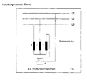
- FIG. 1 shows a three-phase motor as a conventional symbol representation typical three-phase electrical consumer, in which the three Motor windings 1, 2 and 3 are arranged in a typical star connection, each motor winding 1, 2 and 3 each with one end of the connecting line is connected to one of the three three-phase phases L1, L2 and L3.
- the point 5 The circuit forms the star point, at which there is also a neutral conductor can be connected.
- Motor winding 1 is connected to phase L1 in this Embodiment via a protective contact 4, here a protective circuit represents to protect the three-phase motor from a thermal overload.
- the heating of the three-phase motor e.g. in the vicinity of a winding is, if a specified permissible limit temperature is exceeded the protective contact, e.g. a bimetallic switch that is triggered in the form that it separates motor winding 1 from phase L1.
- the protective contact e.g. a bimetallic switch that is triggered in the form that it separates motor winding 1 from phase L1.
- the current passing through each strand results from the ratio of the strand tension to the resistance of the strand.
- the frequency-dependent resistance can be used under resistance be understood, hence the impedance resulting from the effective resistance and gives the reactance.
- the conductor voltage is understood to mean the voltage between the prevailing phases, i.e. in a conventional three-phase network, this is Voltage in Germany, for example, between the individual phases 400 Volt. With reference to the zero point 5 in a typical star connection, this results in then a due to the phase shift between the individual phases String voltage of approx. 231 volts.
- FIG. 3 shows the case that, for example, by triggering the Protective contact one of the three motor windings, in this case the motor winding 1, is separated from phase L1.
- the result of Asymmetry between the remaining phases L2 and L3 the line voltage, see above that in each strand there is a strand tension that is half the Line voltage is equivalent since the two remaining motor windings are inside this circuit are in series and an assumed identical Resistance of each strand is accordingly divided into halves the line voltage in each strand due to the same Voltage divider ratios.
- Phase L1 from via a winding protection contact 4
- Three-phase motor separately, the result is a new circuit as shown in of Figure 5b, i.e. Resistors 1 and 2 are connected in series, resistor 3 parallel to these previously mentioned resistances between phases L2 and L3 is arranged.
- the result is a first strand in which only the resistance 3 is arranged and a second strand in which the resistors 1 and 2 or twice the normal strand resistance is provided, provided that the Resistances are the same.
- the total performance of the system is three times the square of the Conductor voltage divided by twice the phase resistance.
Landscapes
- Protection Of Generators And Motors (AREA)
Abstract
Description
- Figur 1:
- die Sternschaltung eines erfindungsgemässen drehstrombetriebenen Motors
- Figur 2:
- die Berechnung der Leistungsaufnahme bei einer Sternschaltung mit drei angeschlossenen Phasen
- Figur 3:
- die Berechnung der Leistungsaufnahme bei der Sternschaltung mit zwei angeschlossenen Phasen
- Figur 4:
- den Vergleich der Leistungsaufnahmen gemäß Figur 2 und Figur 3
- Figur 5:
- die Dreieckschaltung eines erfindungsgemässen drehstrombetriebenen Motors
- Figur 6:
- die Berechnung der Leistungaufnahme bei einer Dreieckschaltung mit drei angeschlossenen Phasen
- Figur 7:
- die Berechnung der Leistungaufnahme bei einer Dreieckschaltung mit drei angeschlossenen Phasen
- Figur 8:
- der Vergleich der Leistungaufnahme gemäß Figuren 5 und 6
Claims (9)
- Drehfeldbetriebener elektrischer Verbraucher, insbesondere Drehstrommotor, der an die Phasen (L1,L2,L3) eines Mehr-Phasen-Stromnetzes anschliessbar ist und eine Schutzschaltung (4) gegen insbesondere thermische Überlastschäden umfasst, dadurch gekennzeichnet, dass der Verbraucher im Überlastfall mittels der Schutzschaltung (4) von einer Phase (L1) trennbar ist und an den übrigen Phasen (L2, L3) des Stromnetzes angeschlossen bleibt.
- Verbraucher nach Anspruch 1, dadurch gekennzeichnet, dass der Überlastfall durch thermische Überwachung des Verbrauchers detektierbar ist und die Abschaltung der Phase (L1) bei Überschreitung einer vorgegebenen Grenztemperatur erfolgt.
- Verbraucher nach Anspruch 2, dadurch gekennzeichnet, dass ein Temperatursensor vorgesehen ist, um den Überlastfall zu detektieren.
- Verbraucher nach einem der vorherigen Ansprüche, dadurch gekennzeichnet, dass der Verbraucher drei Teilverbraucher (1, 2, 3) aufweist, die jeweils an wenigstens eine Phase (L1, L2, L3) angeschlossen sind.
- Verbraucher nach einem der vorherigen Ansprüche, dadurch gekennzeichnet, dass der Verbraucher ein Drehstrommotor ist und die Teilverbraucher (1, 2, 3) als Motorwicklungen ausgebildet sind, die in Sternund/oder Dreiecksschaltung geschaltet sind.
- Verbraucher nach Anspruch 5, dadurch gekennzeichnet, dass als Schutzschaltung ein Schutzkontakt (4), insbesondere Wicklungsschutzkontakt, vorgesehen ist.
- Verfahren zum Schutz eines drehfeldbetriebenen elektrischen Verbrauchers, insbesondere eines Drehstrommotors, gegen insbesondere thermisch Überlastung, dadurch gekennzeichnet, dass im Überlastfall der Verbraucher von nur einer Phase (L1) der N Phasen (L1, L2, L3) eines Drehstromnetzes getrennt wird.
- Verfahren nach Anspruch 7, dadurch gekennzeichnet, dass die Temperatur des Verbrauchers überwacht wird und die Trennung der einen Phase (L1) bei Überschreitung einer vorgegebenen Grenztemperatur erfolgt.
- Schutzschaltung (4) zur Druchführung eines Verfahrens nach den Ansprüchen 7 oder 8 zur Verwendung in/an einem drehfeldbetriebenen elektrischen Verbraucher, insbesondere einem Drehstrommotor.
Applications Claiming Priority (2)
| Application Number | Priority Date | Filing Date | Title |
|---|---|---|---|
| DE10232208 | 2002-07-17 | ||
| DE2002132208 DE10232208A1 (de) | 2002-07-17 | 2002-07-17 | Überlastschutz für einen drehfeldbetriebenen elektrischen Verbraucher |
Publications (2)
| Publication Number | Publication Date |
|---|---|
| EP1383220A2 true EP1383220A2 (de) | 2004-01-21 |
| EP1383220A3 EP1383220A3 (de) | 2008-12-31 |
Family
ID=29762003
Family Applications (1)
| Application Number | Title | Priority Date | Filing Date |
|---|---|---|---|
| EP03014337A Withdrawn EP1383220A3 (de) | 2002-07-17 | 2003-06-26 | Überlastschutz für einen drehfeldbetriebenen elektrischen Verbraucher |
Country Status (2)
| Country | Link |
|---|---|
| EP (1) | EP1383220A3 (de) |
| DE (1) | DE10232208A1 (de) |
Family Cites Families (7)
| Publication number | Priority date | Publication date | Assignee | Title |
|---|---|---|---|---|
| US3903456A (en) * | 1974-01-28 | 1975-09-02 | Franklin Electric Co Inc | Protector system for an electric motor |
| US4875000A (en) * | 1986-11-26 | 1989-10-17 | The Babcock & Wilcox Company | Current fault detection system and method for AC controller |
| DE4015483C1 (de) * | 1990-05-14 | 1991-10-17 | Zinser Textilmaschinen Gmbh, 7333 Ebersbach, De | |
| TW225056B (de) * | 1991-12-12 | 1994-06-11 | Carrier Corp | |
| DE4210437C2 (de) * | 1992-03-30 | 1994-03-31 | Bockwoldt Carl Michael Dipl Ka | Regelungsverfahren und Regelungsvorrichtung für zumindestens zwei elektrische Motoren |
| DE9409774U1 (de) * | 1994-04-29 | 1995-08-24 | Heidolph-Elektro Gmbh & Co Kg, 93309 Kelheim | Vorrichtung zum Übertemperaturschutz für Drehstrommotoren |
| DE4417883A1 (de) * | 1994-05-21 | 1995-11-23 | Temco Textilmaschkomponent | Zweiphasenthermoschutzelement für Kleinmotore mit Drehstromversorgung |
-
2002
- 2002-07-17 DE DE2002132208 patent/DE10232208A1/de not_active Withdrawn
-
2003
- 2003-06-26 EP EP03014337A patent/EP1383220A3/de not_active Withdrawn
Also Published As
| Publication number | Publication date |
|---|---|
| DE10232208A1 (de) | 2004-04-01 |
| EP1383220A3 (de) | 2008-12-31 |
Similar Documents
| Publication | Publication Date | Title |
|---|---|---|
| DE69414328T2 (de) | Lichtbogenerfassung über die Stromänderung | |
| DE69931347T2 (de) | Zonenweise lichtbogenfehlerdetektion | |
| DE69937860T2 (de) | Schutzschalter mit Lichtbogenfehlerschutz und PTC-Elemente zum Schutz gegen Kurzschluss und Überlastung | |
| EP2619595B1 (de) | Messsystem zur überwachung mindestens einer phase eines systems | |
| DE102004056436B4 (de) | Verfahren und Vorrichtung zur Erkennung von Fehlerstrom-Lichtbögen in elektrischen Stromkreisen | |
| DE19930122C1 (de) | Verfahren zur Verhinderung des Draufschaltens auf in Abzweigen bestehende elektrische Kurzschlüsse und zugehörige Anordnung | |
| EP0452250B1 (de) | Fehlerstrom-Schutzeinrichtung | |
| EP3059828B1 (de) | Vorrichtung und verfahren zur fehlerstromdetektion | |
| DE19739780B4 (de) | Drehstrommotor | |
| EP3574515B1 (de) | Niederspannungs-schutzschaltgerät | |
| EP2169222A2 (de) | Überspannungsschutzgerät für Windenergieanlagen | |
| DE102020215668A1 (de) | Elektrische Maschine | |
| AT520576A2 (de) | Fehlerstromschutzschalter | |
| DE3237800C2 (de) | Schutzeinrichtung für Asynchron-Motoren | |
| DE102016109862A1 (de) | Schaltvorrichtung zum Schalten einer elektrischen Verbindung, Energiespeichersystem für ein Fahrzeug sowie Verfahren zum Schalten einer elektrischen Verbindung | |
| DE3107654C2 (de) | Teilwicklungsschaltung zum Anfahren eines Drehstrommotors | |
| DE3215181A1 (de) | Ueberlastschutzeinrichtung mit feststellung von phasenverlust | |
| EP0757421A2 (de) | Anordnung zur Begrenzung des Kurzschlussstromes in 3-phasigen Drehstromnetzen | |
| DE3228954C2 (de) | Schutzeinrichtung für Asynchron-Motoren | |
| DE10232208A1 (de) | Überlastschutz für einen drehfeldbetriebenen elektrischen Verbraucher | |
| EP0456172B1 (de) | Ein- oder mehrpoliges Motorschutzrelais oder Überstromrelais | |
| EP3750221B1 (de) | Schaltungsanordnung und verfahren zum überlastschutz eines ec-motors | |
| EP1988626A1 (de) | Überlastschutzschaltung | |
| EP1721375B1 (de) | Schutzgerät für einen verbraucherabzweig | |
| DE10018372C2 (de) | Schaltungsanordnung zur Einschaltstrombegrenzung für eine Stromversorgung |
Legal Events
| Date | Code | Title | Description |
|---|---|---|---|
| PUAI | Public reference made under article 153(3) epc to a published international application that has entered the european phase |
Free format text: ORIGINAL CODE: 0009012 |
|
| AK | Designated contracting states |
Kind code of ref document: A2 Designated state(s): AT BE BG CH CY CZ DE DK EE ES FI FR GB GR HU IE IT LI LU MC NL PT RO SE SI SK TR |
|
| AX | Request for extension of the european patent |
Extension state: AL LT LV MK |
|
| PUAL | Search report despatched |
Free format text: ORIGINAL CODE: 0009013 |
|
| AK | Designated contracting states |
Kind code of ref document: A3 Designated state(s): AT BE BG CH CY CZ DE DK EE ES FI FR GB GR HU IE IT LI LU MC NL PT RO SE SI SK TR |
|
| AX | Request for extension of the european patent |
Extension state: AL LT LV MK |
|
| STAA | Information on the status of an ep patent application or granted ep patent |
Free format text: STATUS: REQUEST FOR EXAMINATION WAS MADE |
|
| 17P | Request for examination filed |
Effective date: 20090630 |
|
| AKX | Designation fees paid |
Designated state(s): AT BE BG CH CY CZ DE DK EE ES FI FR GB GR HU IE IT LI LU MC NL PT RO SE SI SK TR |
|
| STAA | Information on the status of an ep patent application or granted ep patent |
Free format text: STATUS: THE APPLICATION IS DEEMED TO BE WITHDRAWN |
|
| 18D | Application deemed to be withdrawn |
Effective date: 20160103 |