EP1383216A1 - Under floor installation - Google Patents
Under floor installation Download PDFInfo
- Publication number
- EP1383216A1 EP1383216A1 EP03014992A EP03014992A EP1383216A1 EP 1383216 A1 EP1383216 A1 EP 1383216A1 EP 03014992 A EP03014992 A EP 03014992A EP 03014992 A EP03014992 A EP 03014992A EP 1383216 A1 EP1383216 A1 EP 1383216A1
- Authority
- EP
- European Patent Office
- Prior art keywords
- cables
- feature
- installation according
- connection plate
- floor
- Prior art date
- Legal status (The legal status is an assumption and is not a legal conclusion. Google has not performed a legal analysis and makes no representation as to the accuracy of the status listed.)
- Granted
Links
Images


Classifications
-
- H—ELECTRICITY
- H02—GENERATION; CONVERSION OR DISTRIBUTION OF ELECTRIC POWER
- H02G—INSTALLATION OF ELECTRIC CABLES OR LINES, OR OF COMBINED OPTICAL AND ELECTRIC CABLES OR LINES
- H02G3/00—Installations of electric cables or lines or protective tubing therefor in or on buildings, equivalent structures or vehicles
- H02G3/36—Installations of cables or lines in walls, floors or ceilings
- H02G3/38—Installations of cables or lines in walls, floors or ceilings the cables or lines being installed in preestablished conduits or ducts
- H02G3/383—Installations of cables or lines in walls, floors or ceilings the cables or lines being installed in preestablished conduits or ducts in floors
Abstract
Description
Die Erfindung betrifft elektrische und gegebenenfalls heizungstechnische
Unterflurinstallationen gemäß dem Oberbegriff des Anspruchs 1, bestimmt für
Gebäude mit Rohboden und Rohwand sowie mit Bodendämmung, Estrich,
Bodenbelag und/oder Putz, insbesondere für Neubauten von Wohngebäuden.The invention relates to electrical and possibly heating technology
Underfloor installations according to the preamble of
Beim Neubau von Wohn- und Bürogebäuden werden zunächst die Wände und Decken bzw. Böden erstellt. Anschließend folgt der Innenausbau. Dazu gehören die Installationsarbeiten für Heizung, Wasser, Elektro usw. Ein Teil der Versorgungsleitungen wird auf dem Rohboden verlegt, bevor Bodendämmung und Estrich eingebracht werden. In die Wände werden Schlitze vorgesehen, die die Leitungen aufnehmen, und Gerätedosen gesetzt. Anschließend werden die Schlitze geschlossen und der Wandputz aufgebracht. Die Kabel und Leitungen enden in den Gerätedosen.When building new residential and office buildings, the walls and Ceilings or floors created. Then the interior work follows. These include the Installation work for heating, water, electrical, etc. Part of the Supply lines are laid on the bare floor before floor insulation and Screed. Slits are provided in the walls, which the Pick up lines, and device sockets placed. Then the slots closed and the wall plaster applied. The cables and wires end in the Gang boxes.
Speziell für Bürogebäude mit Doppelboden gibt es Unterflur-Installationssysteme, die im Doppelboden verlegt werden. An bestimmten Stellen werden in den Boden Anschlussboxen eingesetzt, die mit einer trittfesten Klappe verschlossen werden können. Hinter der Klappe sind Steckdosen, Sicherungen usw. geschützt untergebracht. Dieses Installationssystem erlaubt es, die Anschlussboxen innerhalb des Fußbodenrasters beliebig zu versetzen, weil die Kabel und Leitungen im Zwischenboden völlig frei verlegt sind. Für den klassischen Bodenaufbau mit Estrich sind diese Unterflursysteme jedoch nicht geeignet.There are underfloor installation systems especially for office buildings with raised floors, which are laid in the raised floor. At certain points are in the ground Connection boxes are used, which are closed with a sturdy flap can. Sockets, fuses etc. are protected behind the flap accommodated. This installation system allows the junction boxes inside of the floor grid to move arbitrarily, because the cables in the Intermediate floors are completely free. For classic floor construction with screed these underfloor systems are not suitable.
Auch für den Bodenaufbau mit Estrich existieren Unterflursysteme. Da hier die Anschlusspunkte mitten im Raum angeordnet sind, sind diese Systeme für den Wohnbereich ungeeignet.Underfloor systems also exist for floor construction with screed. Because here Connection points are arranged in the middle of the room, these systems are for the Unsuitable living area.
Der vorliegenden Erfindung liegt die Aufgabe zugrunde, ein Unterflurinstallationssystem für Gebäude mit klassischem Bodenaufbau anzugeben, welches einen hohen Grad an Vorfabrikation und Montageflexibilität besitzt und vor allem die klassische Aufeinanderfolge der Gewerke am Bau beizubehalten gestattet. The present invention is based on the object To specify the underfloor installation system for buildings with a classic floor structure, which has a high degree of prefabrication and assembly flexibility and before Allowing the classic sequence of trades in the building to be maintained.
Diese Aufgabe wird gelöst durch eine Unterflurinstallation mit den Merkmalen des
Anspruchs 1.This task is solved by an underfloor installation with the characteristics of the
Wesentlicher Vorteil der Erfindung ist die Möglichkeit, in großem Umfang fabrikmäßig vorgefertigte Komponenten verwenden zu können, so dass die Installation nicht nur von ausgebildetem Fachpersonal vorgenommen werden kann. Die eingeübte Abfolge der Gewerke wird nicht geändert. Die Höhe des Bodenaufbaus ist innerhalb der konstruktiven Grenzen frei wählbar. Außerdem sind die Installationskomponenten einfach und preiswert, so dass die Kosten auch dann noch im Rahmen bleiben, wenn im Hinblick auf eine hohe Versorgungsdichte und Flexibilität von vornherein eine größere Zahl von Anschlusseinheiten vorgesehen wird.A major advantage of the invention is the possibility of being used on a large scale to be able to use factory-made components so that the Installation cannot only be carried out by trained specialist personnel. The practiced sequence of trades is not changed. The amount of Floor structure is freely selectable within the design limits. Also are the installation components simple and inexpensive, so the cost even then still remain within the scope if in view of a high supply density and Flexibility provided for a larger number of connection units from the outset becomes.
Ein weiterer Vorteil ist, dass die Anschlusspunkte am Übergang vom Boden zur Wand liegen, so dass die Weiterführung der Kabel und Leitungen durch Sockelleistenkanäle möglich ist. Dadurch bleibt das in Wohn- und Bürogebäuden gewohnte Raumbild erhalten.Another advantage is that the connection points at the transition from the floor to the Wall lying so that the continuation of the cables and wires through Skirting channels are possible. This keeps it in residential and office buildings Get the usual room look.
Gemäß einer Weiterbildung der Erfindung überdeckt die Haube die komplette Anschlussplatte.According to a development of the invention, the hood covers the complete Connection plate.
Eine Ausgestaltung der Erfindung sieht vor, dass die Anschlussplatte L-förmig ist mit einem wandseitigen und einem bodenseitigen Schenkel. Eine solche Konstruktion ist sehr einfach und preiswert, bietet eine Vielzahl von Befestigungsmöglichkeiten und ermöglicht variable Anschlüsse.An embodiment of the invention provides that the connection plate is L-shaped with a wall-side and a base-side leg. Such Construction is very simple and inexpensive, offers a variety of Fastening options and enables variable connections.
Gemäß einer Weiterbildung der Erfindung sind an der Anschlussplatte Zugentlastungen für die Enden der Leerrohre und/oder der Kabel und Leitungen vorgesehen.According to a development of the invention are on the connection plate Strain relief for the ends of the empty pipes and / or the cables and wires intended.
Vorzugsweise befinden sich die Zugentlastungen für die Leerrohre auf dem bodenseitigen Schenkel. Die Leerrohre werden in diesem Fall nicht im 90°-Winkel an der Wand hochgezogen, so dass der Platzbedarf minimal wird. The strain reliefs for the empty tubes are preferably located on the bottom leg. In this case, the empty pipes are not at a 90 ° angle pulled up on the wall so that the space requirement is minimal.
Gemäß einer Ausgestaltung der Erfindung besitzt die Haube Durchführungen für Leerrohre und/oder Kabel und Leitungen. Sind diese Durchführungen vorbereitet, so kann der Installateur die entsprechenden Ausschnitte in passender Größe leicht selbst herstellen.According to one embodiment of the invention, the hood has bushings for Empty pipes and / or cables and wires. Are these arrangements prepared the installer can easily find the appropriate cut-outs in a suitable size self made.
Vorteilhafterweise sind die Enden der Kabel und Leitungen anschlussfertig konfektioniert. Dadurch werden die Anschlussarbeiten erheblich vereinfacht und beschleunigt.The ends of the cables and lines are advantageously ready for connection assembled. This simplifies the connection work considerably accelerated.
Gemäß einer Weiterbildung der Erfindung ist ein Aufputz-Kanal vorgesehen mit einer bodenseitigen, zu den Leitungsenden passenden Öffnung. Dieser Kanal deckt zunächst die Öffnung im Boden ab, durch die die Enden der Kabel und Leitungen zugänglich sind. Außerdem ermöglicht er die Verteilung der Kabel und Leitungen zu den vom Verbraucher gewünschten Anschlusspunkten.According to a development of the invention, a surface-mounted duct is provided with a bottom-side opening that matches the cable ends. This channel covers First, open the opening in the floor through which the ends of the cables and wires are accessible. It also enables the distribution of cables and wires the connection points desired by the consumer.
Gegebenenfalls kann auch eine Aufputz-Gerätebox mit einer bodenseitigen, zu den Leitungsenden passenden Öffnung vorgesehen sein. Diese Gerätebox kann elektrische Installationsgeräte aufnehmen, beispielsweise eine oder mehrere Steckdosen.If necessary, a surface-mounted device box with a bottom side can also be used Suitable opening ends are provided. This device box can record electrical installation devices, for example one or more Outlets.
Anhand der Zeichnung soll die Erfindung in Form eines Ausführungsbeispiels näher erläutert werden. Es zeigen jeweils rein schematisch
- Fig. 1
- eine Anschlussplatte, montiert auf Rohboden und Rohwand,
- Fig. 2
- eine alternative Anschlussplatte,
- Fig. 3
- die Anschlussplatte der Fig. 1, abgedeckt mit einer Haube,
- Fig. 4
- eine Haube mit vorbereiteten Durchführungen für Leerrohre und/oder Kabel und Leitungen,
- Fig. 5
- die Anordnung der Fig. 3 nach Anbringen einer Bodendämmschicht,
- Fig. 6
- die Anordnung der Fig. 5 nach Anbringen einer Estrichschicht,
- Fig. 7
- die Anordnung der Fig. 6 nach Anbringen einer Putzschicht,
- Fig. 8
- die Anordnung der Fig. 7 nach Anbringen eines Bodenbelags,
- Fig. 9
- die Anordnung der Fig. 8 nach niveaugleichem Abschneiden des überstehenden Teils der Haube,
- Fig. 10
- die Anordnung der Fig. 9 nach Aufsetzen eines Sockelleistenkanals mit Aufputz-Gerätebox und
- Fig. 11
- einen Schnitt durch die Anordnung der Fig. 10.
- Fig. 1
- a connection plate, mounted on the raw floor and raw wall,
- Fig. 2
- an alternative connection plate,
- Fig. 3
- 1, covered with a hood,
- Fig. 4
- a hood with prepared bushings for empty pipes and / or cables and wires,
- Fig. 5
- 3 after the installation of a floor insulation layer,
- Fig. 6
- 5 after applying a screed layer,
- Fig. 7
- 6 after the application of a plaster layer,
- Fig. 8
- 7 after installing a floor covering,
- Fig. 9
- 8 after cutting off the protruding part of the hood at the same level,
- Fig. 10
- the arrangement of FIG. 9 after placing a baseboard channel with surface-mounted device box and
- Fig. 11
- a section through the arrangement of FIG. 10th
Die Fig. 1 bis 10 zeigen rein schematisch und in Schrägansicht eine elektrische und gegebenenfalls heizungstechnische Unterflurinstallation für Gebäude, insbesondere für Neubauten.1 to 10 show purely schematically and in an oblique view an electrical and if necessary, underfloor heating installation for buildings, in particular for new buildings.
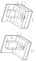
Fig. 1 zeigt einen Ausschnitt aus einem Gebäude. In einer Ecke, gebildet durch
einen Rohboden 1 und eine Rohwand 2, ist eine L-förmige Anschlussplatte 20, 21
montiert. Auf dem bodenseitigen Schenkel 21 der Anschlussplatte sind mit Hilfe von
Zugentlastungen 22 die Enden von Leerrohren 10 fixiert. In den Leerrohren 10 sind
Kabel bzw. Leitungen 11 geführt. Deren Enden 12 sind mit Hilfe von weiteren
Zugentlastungen 22 am wandseitigen Schenkel 20 der Anschlussplatte festgelegt.
Die Anschlussplatte 20, 21 ist mit einer Reihe von Bohrungen 23 versehen, mit
deren Hilfe sie an Boden 1 oder Wand 2 fixiert werden kann.Fig. 1 shows a section of a building. In a corner, formed by
an
Fig. 2 zeigt eine alternative Anschlussplatte. Hier sind die die Enden der Leerrohre
10 haltenden Zugentlastungen 22 seitlich angebracht. Im übrigen entspricht diese
Anschlussplatte der der Fig. 1.Fig. 2 shows an alternative connection plate. Here are the ends of the
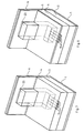
Fig. 3 zeigt die Anschlussplatte 20, 21 mit aufgesetzter Haube. Die Haube 23 ist so
ausgebildet, dass weder Estrich noch Putz eindringen können. Fig. 3 shows the
Fig. 4 zeigt eine Ausführungsform einer solchen Haube 23. Man erkennt an der
Unterseite vorbereitete Öffnungen 24 für die Leerrohre 10 oder Kabel und
Leitungen 11.Fig. 4 shows an embodiment of such a
Fig. 5 zeigt die Anordnung der Fig. 3, nachdem eine Bodendämmschicht 3
angebracht wurde. Die Leerrohre 10 sowie der bodenseitige Schenkel der Haube 23
sind bedeckt.FIG. 5 shows the arrangement of FIG. 3 after a
Fig. 6 zeigt die Anordnung der Fig. 5 nach Anbringen einer Estrichschicht 4.FIG. 6 shows the arrangement of FIG. 5 after applying a
Fig. 7 zeigt die Anordnung der Fig. 6 nach Anbringen einer Putzschicht 6 auf die
Rohwand 2. Die Haube 23 ist noch immer zugänglich.Fig. 7 shows the arrangement of Fig. 6 after applying a
Fig. 8 zeigt die Anordnung der Fig. 7 nach Aufbringen eines Bodenbelags 5 auf den
Estrich 4. Die Haube 23 ist noch immer zugänglich.Fig. 8 shows the arrangement of Fig. 7 after applying a floor covering 5 on the
Fig. 9 zeigt die Anordnung der Fig. 8, nachdem das freiliegende Teil 23' der Haube
23 niveaugleich mit dem Bodenbelag 5 bzw. der Putzschicht 6 abgeschnitten wurde.
Im Boden ist eine Öffnung entstanden, durch die die Enden 12 der Kabel und
Leitungen 11 für weiterführende Installationsarbeiten gut zugänglich sind. Sind die
Enden 12 der Kabel und Leitungen 11 anschlussfertig konfektioniert, beispielsweise
mit steckbaren Kupplungen versehen, können die weiterführenden
Installationsarbeiten auch von angelernten Personen ausgeführt werden.Fig. 9 shows the arrangement of Fig. 8 after the exposed part 23 'of the
Fig. 10 zeigt die Endsituation. Auf die durch das Abschneiden der Haube 23
entstandene Bodenöffnung sind ein Sockelleistenkanal 30 sowie eine Aufputz-Gerätebox
31 aufgesetzt. Kanal 30 und Box 31 besitzen bodenseitige Öffnungen,
durch die der Zugang zu den Kabeln und Leitungen 11 möglich ist. Im
Sockelleistenkanal 30 liegen weitere Kabel und Leitungen 32, die zu weiteren
Anschlusseinheiten führen.Fig. 10 shows the final situation. By cutting off the
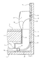
Fig. 11 zeigt in vergrößerter Darstellung einen Längsschnitt durch die Anordnung
der Fig. 10. Man erkennt die auf Rohboden 1 und Rohwand 2 montierte L-förmige
Anschlussplatte, auf deren bodenseitigem Schenkel 21 mit Hilfe der
Zugentlastungen 22 die Enden der Leerrohre 10 und an deren wandseitigem
Schenkel 20 mit Hilfe von weiteren Zugentlastungen 22 die Enden 12 der Kabel und
Leitungen 11 fixiert sind. Die Kabel und Leitungen 11 sind in den Leerrohren 10
geführt.Fig. 11 shows an enlarged view of a longitudinal section through the
Auf die Anschlussplatte 20, 21 aufgesetzt erkennt man die Haube 23, deren über
das Niveau des Bodenaufbaus, bestehend aus Bodendämmschicht 3, Estrichschicht
4 und Bodenbelag 5 hinausstehendes Ende niveaugleich abgeschnitten wurde. Die
Schnittführung ist auch niveaugleich mit der auf der Rohwand aufgetragenen
Putzschicht 6 geführt.On the
Des weiteren erkennt man im Querschnitt die Aufputz-Gerätebox 31 mit sich daran
anschließendem Sockelleistenkanal 30.Furthermore, the cross-section of the surface-mounted
Es versteht sich, dass anstelle von oder auch zusätzlich zu den Leerrohren 10 und
Kabeln und Leitungen 11 auch flüssigkeitsführende Rohre, beispielsweise
Heizungsrohre, verlegt werden können. Auch Rohre können später in einem
Sockelleistenkanal weitergeführt werden.It goes without saying that instead of or in addition to the
Claims (9)
Applications Claiming Priority (2)
| Application Number | Priority Date | Filing Date | Title |
|---|---|---|---|
| DE20210774U | 2002-07-17 | ||
| DE20210774U DE20210774U1 (en) | 2002-07-17 | 2002-07-17 | Underground installation |
Publications (2)
| Publication Number | Publication Date |
|---|---|
| EP1383216A1 true EP1383216A1 (en) | 2004-01-21 |
| EP1383216B1 EP1383216B1 (en) | 2008-02-27 |
Family
ID=27798402
Family Applications (1)
| Application Number | Title | Priority Date | Filing Date |
|---|---|---|---|
| EP03014992A Expired - Lifetime EP1383216B1 (en) | 2002-07-17 | 2003-07-02 | Under floor installation |
Country Status (7)
| Country | Link |
|---|---|
| EP (1) | EP1383216B1 (en) |
| AT (1) | ATE387741T1 (en) |
| DE (2) | DE20210774U1 (en) |
| DK (1) | DK1383216T3 (en) |
| ES (1) | ES2301735T3 (en) |
| NO (1) | NO322882B1 (en) |
| PT (1) | PT1383216E (en) |
Cited By (1)
| Publication number | Priority date | Publication date | Assignee | Title |
|---|---|---|---|---|
| EP1988613A2 (en) | 2007-05-03 | 2008-11-05 | In-akustik GmbH & Co. KG | Device for installing energy and data cables and system components |
Families Citing this family (2)
| Publication number | Priority date | Publication date | Assignee | Title |
|---|---|---|---|---|
| DE202004000759U1 (en) * | 2004-01-20 | 2005-06-02 | Tehalit Gmbh & Co. Kg | Connecting device for heavy-current and / or low-voltage cables |
| FR2947852B1 (en) * | 2009-07-10 | 2014-08-22 | Elyssa | HOUSING FOR COMBINING AND ORIENTING SHEATHES, PIPES, CABLES IN A FLOORED CHAPE |
Citations (4)
| Publication number | Priority date | Publication date | Assignee | Title |
|---|---|---|---|---|
| DE3734733A1 (en) * | 1986-10-30 | 1988-05-05 | Domotec Ag | Pipe support for at least one curved pipeline |
| EP0529740A1 (en) * | 1991-08-24 | 1993-03-03 | SCHMIDT REUTER INGENIEURGESELLSCHAFT mbH & PARTNER KOMMANDITGESELLSCHAFT | Under-floor duct system |
| DE19534458A1 (en) * | 1995-09-16 | 1997-03-20 | Johannes Riepe | Installation system for laying of cables and gas/water pipes in wall of room |
| DE20102443U1 (en) * | 2001-02-13 | 2002-06-27 | Uponor Innovation Ab | Guide device for a pipe laid in a concrete ceiling |
-
2002
- 2002-07-17 DE DE20210774U patent/DE20210774U1/en not_active Expired - Lifetime
-
2003
- 2003-07-02 DE DE50309245T patent/DE50309245D1/en not_active Expired - Lifetime
- 2003-07-02 PT PT03014992T patent/PT1383216E/en unknown
- 2003-07-02 ES ES03014992T patent/ES2301735T3/en not_active Expired - Lifetime
- 2003-07-02 DK DK03014992T patent/DK1383216T3/en active
- 2003-07-02 EP EP03014992A patent/EP1383216B1/en not_active Expired - Lifetime
- 2003-07-02 AT AT03014992T patent/ATE387741T1/en active
- 2003-07-07 NO NO20033101A patent/NO322882B1/en not_active IP Right Cessation
Patent Citations (4)
| Publication number | Priority date | Publication date | Assignee | Title |
|---|---|---|---|---|
| DE3734733A1 (en) * | 1986-10-30 | 1988-05-05 | Domotec Ag | Pipe support for at least one curved pipeline |
| EP0529740A1 (en) * | 1991-08-24 | 1993-03-03 | SCHMIDT REUTER INGENIEURGESELLSCHAFT mbH & PARTNER KOMMANDITGESELLSCHAFT | Under-floor duct system |
| DE19534458A1 (en) * | 1995-09-16 | 1997-03-20 | Johannes Riepe | Installation system for laying of cables and gas/water pipes in wall of room |
| DE20102443U1 (en) * | 2001-02-13 | 2002-06-27 | Uponor Innovation Ab | Guide device for a pipe laid in a concrete ceiling |
Cited By (2)
| Publication number | Priority date | Publication date | Assignee | Title |
|---|---|---|---|---|
| EP1988613A2 (en) | 2007-05-03 | 2008-11-05 | In-akustik GmbH & Co. KG | Device for installing energy and data cables and system components |
| DE102007020958A1 (en) | 2007-05-03 | 2008-11-06 | In-Akustik Gmbh & Co. Kg Unterhaltungselektronik | Device for installing power and data cables and system components |
Also Published As
| Publication number | Publication date |
|---|---|
| ES2301735T3 (en) | 2008-07-01 |
| ATE387741T1 (en) | 2008-03-15 |
| PT1383216E (en) | 2008-05-29 |
| DK1383216T3 (en) | 2008-06-23 |
| NO20033101D0 (en) | 2003-07-07 |
| EP1383216B1 (en) | 2008-02-27 |
| DE20210774U1 (en) | 2003-11-27 |
| DE50309245D1 (en) | 2008-04-10 |
| NO322882B1 (en) | 2006-12-18 |
Similar Documents
| Publication | Publication Date | Title |
|---|---|---|
| DE2142127A1 (en) | Power supply device for ceiling structures and ceiling structures using the power supply device | |
| DE2658708A1 (en) | ROUTING FOR ELECTRICAL DISTRIBUTION AND TELECOMMUNICATION CABLES IN BUILDINGS | |
| EP3480380A1 (en) | Module for the erection of buildings in modular construction system | |
| EP1383216B1 (en) | Under floor installation | |
| DE3910629A1 (en) | Cavity floor with cable guides | |
| DE2721797C3 (en) | Electrical installation system | |
| DE19735957C2 (en) | Process for the production of double-walled components and components produced thereafter with pre-installation | |
| EP0305338A2 (en) | Kit of parts and its utilization for constructing channels and boxes in buildings | |
| CH699263B1 (en) | Underfloor trunking system. | |
| DE19963046B4 (en) | Kit for producing at least one supply line system in a building | |
| DE102019132612A1 (en) | Room cell for buildings | |
| DE19848887C1 (en) | Wall component has cover plate mounted on filler parts, base plate central access aperture in which cable connecting socket with closed bottom part and central part is fixed | |
| DE1231330B (en) | Procedure and arrangement for the concealed and underfloor installation of electrical lines | |
| DE19745385A1 (en) | Assembly method of electrical installation e.g. for floor plan of flat | |
| DE102013102232A1 (en) | Flush-mounted box, in particular flush-mounted distribution box | |
| DE102020000361B4 (en) | Plate-shaped laying device and system and arrangement with several of these laying devices | |
| DE6810729U (en) | POWER STRIP SYSTEM | |
| DE202020000242U1 (en) | Plate-shaped laying device and system and arrangement with several of these laying devices | |
| DE1640395B2 (en) | METHOD OF LAYING ELECTRICAL CABLES IN BUILDINGS | |
| EP2445069A1 (en) | Corner profile system | |
| DE3436073A1 (en) | Coupling piece for a cable duct | |
| DE10103750A1 (en) | Installation channel for services cables in buildings, is formed from many interlockable shapes having various side pieces | |
| DE10209674A1 (en) | Structural element integrated in building wall has pipeline sections passing through for connecting into water or heating pipes running through building wall | |
| DE102015005619B4 (en) | Installation duct | |
| DE1802882C3 (en) | Electrical distribution system embedded in a building ceiling |
Legal Events
| Date | Code | Title | Description |
|---|---|---|---|
| PUAI | Public reference made under article 153(3) epc to a published international application that has entered the european phase |
Free format text: ORIGINAL CODE: 0009012 |
|
| AK | Designated contracting states |
Kind code of ref document: A1 Designated state(s): AT BE BG CH CY CZ DE DK EE ES FI FR GB GR HU IE IT LI LU MC NL PT RO SE SI SK TR |
|
| AX | Request for extension of the european patent |
Extension state: AL LT LV MK |
|
| 17P | Request for examination filed |
Effective date: 20040302 |
|
| AKX | Designation fees paid |
Designated state(s): AT BE BG CH CY CZ DE DK EE ES FI FR GB GR HU IE IT LI LU MC NL PT RO SE SI SK TR |
|
| RAP1 | Party data changed (applicant data changed or rights of an application transferred) |
Owner name: TEHALIT GMBH |
|
| RAP1 | Party data changed (applicant data changed or rights of an application transferred) |
Owner name: TEHALIT GMBH |
|
| 17Q | First examination report despatched |
Effective date: 20060928 |
|
| GRAP | Despatch of communication of intention to grant a patent |
Free format text: ORIGINAL CODE: EPIDOSNIGR1 |
|
| GRAS | Grant fee paid |
Free format text: ORIGINAL CODE: EPIDOSNIGR3 |
|
| GRAA | (expected) grant |
Free format text: ORIGINAL CODE: 0009210 |
|
| AK | Designated contracting states |
Kind code of ref document: B1 Designated state(s): AT BE BG CH CY CZ DE DK EE ES FI FR GB GR HU IE IT LI LU MC NL PT RO SE SI SK TR |
|
| REG | Reference to a national code |
Ref country code: GB Ref legal event code: FG4D Free format text: NOT ENGLISH |
|
| REG | Reference to a national code |
Ref country code: CH Ref legal event code: EP |
|
| REG | Reference to a national code |
Ref country code: IE Ref legal event code: FG4D Free format text: LANGUAGE OF EP DOCUMENT: GERMAN |
|
| REF | Corresponds to: |
Ref document number: 50309245 Country of ref document: DE Date of ref document: 20080410 Kind code of ref document: P |
|
| REG | Reference to a national code |
Ref country code: PT Ref legal event code: SC4A Free format text: AVAILABILITY OF NATIONAL TRANSLATION Effective date: 20080515 |
|
| REG | Reference to a national code |
Ref country code: SE Ref legal event code: TRGR |
|
| REG | Reference to a national code |
Ref country code: GR Ref legal event code: EP Ref document number: 20080401279 Country of ref document: GR |
|
| REG | Reference to a national code |
Ref country code: DK Ref legal event code: T3 |
|
| REG | Reference to a national code |
Ref country code: CH Ref legal event code: NV Representative=s name: PATENTANWAELTE SCHAAD, BALASS, MENZL & PARTNER AG |
|
| REG | Reference to a national code |
Ref country code: ES Ref legal event code: FG2A Ref document number: 2301735 Country of ref document: ES Kind code of ref document: T3 |
|
| PG25 | Lapsed in a contracting state [announced via postgrant information from national office to epo] |
Ref country code: SI Free format text: LAPSE BECAUSE OF FAILURE TO SUBMIT A TRANSLATION OF THE DESCRIPTION OR TO PAY THE FEE WITHIN THE PRESCRIBED TIME-LIMIT Effective date: 20080227 |
|
| PG25 | Lapsed in a contracting state [announced via postgrant information from national office to epo] |
Ref country code: SK Free format text: LAPSE BECAUSE OF FAILURE TO SUBMIT A TRANSLATION OF THE DESCRIPTION OR TO PAY THE FEE WITHIN THE PRESCRIBED TIME-LIMIT Effective date: 20080227 |
|
| ET | Fr: translation filed | ||
| PG25 | Lapsed in a contracting state [announced via postgrant information from national office to epo] |
Ref country code: RO Free format text: LAPSE BECAUSE OF FAILURE TO SUBMIT A TRANSLATION OF THE DESCRIPTION OR TO PAY THE FEE WITHIN THE PRESCRIBED TIME-LIMIT Effective date: 20080227 |
|
| PLBE | No opposition filed within time limit |
Free format text: ORIGINAL CODE: 0009261 |
|
| STAA | Information on the status of an ep patent application or granted ep patent |
Free format text: STATUS: NO OPPOSITION FILED WITHIN TIME LIMIT |
|
| 26N | No opposition filed |
Effective date: 20081128 |
|
| PG25 | Lapsed in a contracting state [announced via postgrant information from national office to epo] |
Ref country code: EE Free format text: LAPSE BECAUSE OF FAILURE TO SUBMIT A TRANSLATION OF THE DESCRIPTION OR TO PAY THE FEE WITHIN THE PRESCRIBED TIME-LIMIT Effective date: 20080227 Ref country code: BG Free format text: LAPSE BECAUSE OF FAILURE TO SUBMIT A TRANSLATION OF THE DESCRIPTION OR TO PAY THE FEE WITHIN THE PRESCRIBED TIME-LIMIT Effective date: 20080527 |
|
| PG25 | Lapsed in a contracting state [announced via postgrant information from national office to epo] |
Ref country code: CY Free format text: LAPSE BECAUSE OF FAILURE TO SUBMIT A TRANSLATION OF THE DESCRIPTION OR TO PAY THE FEE WITHIN THE PRESCRIBED TIME-LIMIT Effective date: 20080227 |
|
| PG25 | Lapsed in a contracting state [announced via postgrant information from national office to epo] |
Ref country code: HU Free format text: LAPSE BECAUSE OF FAILURE TO SUBMIT A TRANSLATION OF THE DESCRIPTION OR TO PAY THE FEE WITHIN THE PRESCRIBED TIME-LIMIT Effective date: 20080828 |
|
| PG25 | Lapsed in a contracting state [announced via postgrant information from national office to epo] |
Ref country code: TR Free format text: LAPSE BECAUSE OF FAILURE TO SUBMIT A TRANSLATION OF THE DESCRIPTION OR TO PAY THE FEE WITHIN THE PRESCRIBED TIME-LIMIT Effective date: 20080227 |
|
| PGFP | Annual fee paid to national office [announced via postgrant information from national office to epo] |
Ref country code: CZ Payment date: 20110623 Year of fee payment: 9 Ref country code: PT Payment date: 20110624 Year of fee payment: 9 |
|
| PGFP | Annual fee paid to national office [announced via postgrant information from national office to epo] |
Ref country code: LU Payment date: 20110722 Year of fee payment: 9 |
|
| PGFP | Annual fee paid to national office [announced via postgrant information from national office to epo] |
Ref country code: DK Payment date: 20110725 Year of fee payment: 9 Ref country code: FR Payment date: 20110729 Year of fee payment: 9 Ref country code: CH Payment date: 20110725 Year of fee payment: 9 Ref country code: MC Payment date: 20110721 Year of fee payment: 9 Ref country code: IE Payment date: 20110719 Year of fee payment: 9 |
|
| PGFP | Annual fee paid to national office [announced via postgrant information from national office to epo] |
Ref country code: AT Payment date: 20110720 Year of fee payment: 9 Ref country code: SE Payment date: 20110721 Year of fee payment: 9 Ref country code: GR Payment date: 20110721 Year of fee payment: 9 Ref country code: GB Payment date: 20110721 Year of fee payment: 9 Ref country code: ES Payment date: 20110728 Year of fee payment: 9 Ref country code: FI Payment date: 20110720 Year of fee payment: 9 Ref country code: DE Payment date: 20110628 Year of fee payment: 9 |
|
| PGFP | Annual fee paid to national office [announced via postgrant information from national office to epo] |
Ref country code: BE Payment date: 20110725 Year of fee payment: 9 Ref country code: IT Payment date: 20110727 Year of fee payment: 9 Ref country code: NL Payment date: 20110725 Year of fee payment: 9 |
|
| REG | Reference to a national code |
Ref country code: DE Ref legal event code: R082 Ref document number: 50309245 Country of ref document: DE Representative=s name: , |
|
| REG | Reference to a national code |
Ref country code: PT Ref legal event code: MM4A Free format text: LAPSE DUE TO NON-PAYMENT OF FEES Effective date: 20130102 |
|
| BERE | Be: lapsed |
Owner name: TEHALIT G.M.B.H. Effective date: 20120731 |
|
| REG | Reference to a national code |
Ref country code: NL Ref legal event code: V1 Effective date: 20130201 |
|
| PG25 | Lapsed in a contracting state [announced via postgrant information from national office to epo] |
Ref country code: MC Free format text: LAPSE BECAUSE OF NON-PAYMENT OF DUE FEES Effective date: 20120731 |
|
| REG | Reference to a national code |
Ref country code: CH Ref legal event code: PL |
|
| REG | Reference to a national code |
Ref country code: GR Ref legal event code: ML Ref document number: 20080401279 Country of ref document: GR Effective date: 20130104 |
|
| REG | Reference to a national code |
Ref country code: SE Ref legal event code: EUG |
|
| REG | Reference to a national code |
Ref country code: AT Ref legal event code: MM01 Ref document number: 387741 Country of ref document: AT Kind code of ref document: T Effective date: 20120702 |
|
| GBPC | Gb: european patent ceased through non-payment of renewal fee |
Effective date: 20120702 |
|
| REG | Reference to a national code |
Ref country code: DK Ref legal event code: EBP |
|
| REG | Reference to a national code |
Ref country code: FR Ref legal event code: ST Effective date: 20130329 |
|
| PG25 | Lapsed in a contracting state [announced via postgrant information from national office to epo] |
Ref country code: NL Free format text: LAPSE BECAUSE OF NON-PAYMENT OF DUE FEES Effective date: 20130201 Ref country code: CH Free format text: LAPSE BECAUSE OF NON-PAYMENT OF DUE FEES Effective date: 20120731 Ref country code: LI Free format text: LAPSE BECAUSE OF NON-PAYMENT OF DUE FEES Effective date: 20120731 Ref country code: SE Free format text: LAPSE BECAUSE OF NON-PAYMENT OF DUE FEES Effective date: 20120703 Ref country code: FI Free format text: LAPSE BECAUSE OF NON-PAYMENT OF DUE FEES Effective date: 20120702 Ref country code: DE Free format text: LAPSE BECAUSE OF NON-PAYMENT OF DUE FEES Effective date: 20130201 Ref country code: FR Free format text: LAPSE BECAUSE OF NON-PAYMENT OF DUE FEES Effective date: 20120731 Ref country code: CZ Free format text: LAPSE BECAUSE OF NON-PAYMENT OF DUE FEES Effective date: 20120702 Ref country code: GB Free format text: LAPSE BECAUSE OF NON-PAYMENT OF DUE FEES Effective date: 20120702 |
|
| REG | Reference to a national code |
Ref country code: IE Ref legal event code: MM4A |
|
| REG | Reference to a national code |
Ref country code: DE Ref legal event code: R119 Ref document number: 50309245 Country of ref document: DE Effective date: 20130201 |
|
| PG25 | Lapsed in a contracting state [announced via postgrant information from national office to epo] |
Ref country code: PT Free format text: LAPSE BECAUSE OF NON-PAYMENT OF DUE FEES Effective date: 20130102 Ref country code: IT Free format text: LAPSE BECAUSE OF NON-PAYMENT OF DUE FEES Effective date: 20120702 Ref country code: GR Free format text: LAPSE BECAUSE OF NON-PAYMENT OF DUE FEES Effective date: 20130204 Ref country code: BE Free format text: LAPSE BECAUSE OF NON-PAYMENT OF DUE FEES Effective date: 20120731 |
|
| PG25 | Lapsed in a contracting state [announced via postgrant information from national office to epo] |
Ref country code: AT Free format text: LAPSE BECAUSE OF NON-PAYMENT OF DUE FEES Effective date: 20120702 |
|
| PG25 | Lapsed in a contracting state [announced via postgrant information from national office to epo] |
Ref country code: DK Free format text: LAPSE BECAUSE OF NON-PAYMENT OF DUE FEES Effective date: 20120731 Ref country code: IE Free format text: LAPSE BECAUSE OF NON-PAYMENT OF DUE FEES Effective date: 20120702 |
|
| REG | Reference to a national code |
Ref country code: ES Ref legal event code: FD2A Effective date: 20131021 |
|
| PG25 | Lapsed in a contracting state [announced via postgrant information from national office to epo] |
Ref country code: ES Free format text: LAPSE BECAUSE OF NON-PAYMENT OF DUE FEES Effective date: 20120703 |
|
| PG25 | Lapsed in a contracting state [announced via postgrant information from national office to epo] |
Ref country code: LU Free format text: LAPSE BECAUSE OF NON-PAYMENT OF DUE FEES Effective date: 20120702 |