EP1383212A1 - Apparatus and method for quality assurance of crimp connections - Google Patents
Apparatus and method for quality assurance of crimp connections Download PDFInfo
- Publication number
- EP1383212A1 EP1383212A1 EP03015348A EP03015348A EP1383212A1 EP 1383212 A1 EP1383212 A1 EP 1383212A1 EP 03015348 A EP03015348 A EP 03015348A EP 03015348 A EP03015348 A EP 03015348A EP 1383212 A1 EP1383212 A1 EP 1383212A1
- Authority
- EP
- European Patent Office
- Prior art keywords
- crimping
- value
- height
- actual
- correction
- Prior art date
- Legal status (The legal status is an assumption and is not a legal conclusion. Google has not performed a legal analysis and makes no representation as to the accuracy of the status listed.)
- Granted
Links
Images

Classifications
-
- H—ELECTRICITY
- H01—ELECTRIC ELEMENTS
- H01R—ELECTRICALLY-CONDUCTIVE CONNECTIONS; STRUCTURAL ASSOCIATIONS OF A PLURALITY OF MUTUALLY-INSULATED ELECTRICAL CONNECTING ELEMENTS; COUPLING DEVICES; CURRENT COLLECTORS
- H01R43/00—Apparatus or processes specially adapted for manufacturing, assembling, maintaining, or repairing of line connectors or current collectors or for joining electric conductors
- H01R43/04—Apparatus or processes specially adapted for manufacturing, assembling, maintaining, or repairing of line connectors or current collectors or for joining electric conductors for forming connections by deformation, e.g. crimping tool
- H01R43/048—Crimping apparatus or processes
- H01R43/0486—Crimping apparatus or processes with force measuring means
-
- H—ELECTRICITY
- H01—ELECTRIC ELEMENTS
- H01R—ELECTRICALLY-CONDUCTIVE CONNECTIONS; STRUCTURAL ASSOCIATIONS OF A PLURALITY OF MUTUALLY-INSULATED ELECTRICAL CONNECTING ELEMENTS; COUPLING DEVICES; CURRENT COLLECTORS
- H01R43/00—Apparatus or processes specially adapted for manufacturing, assembling, maintaining, or repairing of line connectors or current collectors or for joining electric conductors
- H01R43/04—Apparatus or processes specially adapted for manufacturing, assembling, maintaining, or repairing of line connectors or current collectors or for joining electric conductors for forming connections by deformation, e.g. crimping tool
- H01R43/048—Crimping apparatus or processes
- H01R43/0488—Crimping apparatus or processes with crimp height adjusting means
Definitions
- the present invention relates to a method and a device for Quality assurance of crimp connections on crimping devices.
- the electrical line must be from Electrical connection tightly encloses around a good power transmission ensure and also to prevent cavities that corrode being able to lead.
- the closing height of the tool in relation to the thickness of Electric line is particularly important here. If the closing height is too high, so the compound may have too low a tensile strength. Is the Closing height too low, it can lead to a termination of the strands and also in this case too low a tensile strength. The setting of the Correct crimp height is therefore an important issue in crimping devices.
- DE 43 37 796 A1 discloses a method for monitoring the quality of Crimp connections specified, in which the temporal force curves of a Plurality of reference measurements are captured as traces and a averaged measuring curve is formed, to which an upper and a lower spaced curve are created, so that therefrom a tolerance band arises.
- a crimping process to be monitored it is checked whether the off This crimping process determined entirely within the surface of the Tolerance band is. Faulty crimping can be determined by this become.
- the invention is therefore based on the object, a method for Quality assurance of crimps to create, with that too Long-term operations can be detected safely.
- the actual value becomes during the crimping operations the crimping force and / or crimp height are constantly within predetermined upper and / or lower tolerance masses of the crimping force and / or crimping height measured and after reaching a correction reading by several Measured actual values, a corrected readjustment of the crimp height carried out.
- commissioning a crimping device is at the beginning of Production start the machine temperature approximately constant. With the However, time heats the device and it is an extension of the Machine body, which is an increase in the crimp height and at the same time Reduction of the crimping force has.
- correction value a correction measure is given, which is preferred is about half of a tolerance measure. This correction reading is at the same time the mean of the measured actual values of the individual Crimps.
- the heating phase of the crimping device usually find several corrected new settings of crimp height instead. This will be as long as possible carried out until the crimping device has reached its temperature stability and the desired value of the crimp height in a predetermined minimum range is complied with.
- the apparatus for performing the method is with a via a Drive connecting rod back and forth offset movable die part and a fixed die part with a device for pressing height adjustment Mistake. It is characterized by the fact that the drive connecting rod with a in this case in its longitudinal direction displaceable die part and with a die Displacement causing adjusting drive for fine adjustment of the pressing height is provided, wherein the adjusting drive via a comparative target lst control is controlled.
- the actual value of the control is determined by an actual value detector attached to the adjusting drive tapped.
- the setpoint can be at the control unit of Device can be adjusted or even from a calculated Reference size of the Crimpkraftwait be specified.
- the target value The regulation is then about the force curve during the crimping process determined.
- a comparator is provided, in which the desired value from control unit or the crimp force during the crimping process is stored.
- the adjustment consists of a stepper motor and a gearbox.
- the adjusting element itself is a perpendicular to the Direction of movement of the drive connecting rod in a hole located therein inserted eccentric pin.
- the axis of rotation of the eccentric pin is with the Is-Wertermittler connected, which indicates the position value of the eccentric pin transmitted the comparator.
- the adjustment accuracy of the eccentric pin is 0.002 mm.
- the actual value of the Crimpkraftverlaufs is throughout the Crimping process measured and with the predetermined in the comparator Target value of the Crimpkraftverlaufs compared. In case of deviations between the Actual and the desired value, a correction of the Crimpkraftverlaufs to the target value, by changing the pressing height.
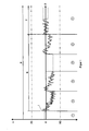
- the method is as it takes place in a production process shown schematically.
- X the target amount of the crimp height H is designated. On the time axis Z this is a straight line.
- X1 the lower one Tolerance measure of the crimp height H and with X2 the upper tolerance of the Crimp height H is called.
- the within this tolerance dimensions X1 or X2 produced crimp are qualitatively not too objectionable.
- the production process is divided into phases 1 to 6. In the Phase 1 after commissioning of the crimping device is the Device temperature approximately constant. The actual values of the crimp height H are not drawn here and move in a narrow Tolerance range around the nominal dimension X.
- phase 2 a first warming occurs and thus also extension of the device body instead of what a Increasing the crimp height H leads.
- the actual values l of the individual Crimping processes tend to look down on the graph, that is for a higher crimp height H or a lower crimp force.
- the correction reading Y represents an average value several measured actual values 1. This correction measured value Y amounts to about half of a tolerance measure, as here the tolerance X2.
- phase 2 can be repeated several times, and while until the crimping device has reached its operating temperature and a Process stability is given, as shown in the phase 6.
- the Heating E of the crimping device in the present example comprises the Phases 2 to 5.
- the temperature stability T has occurred.
- the entire production process P consequently comprises Phase 1 with approximately constant Temperature of the crimping, the phases 2 to 5 the area E in the Heating of the crimping takes place and the phase 6 at the Crimping device their operating temperature T and thus their process stability has reached.
- the means for pressing height adjustment is shown as to a device for carrying out the method is used.
- the Device consists essentially of the drive rod 11, the Die part 10, the adjustment 14 and the comparative set / lst control 15.
- the drive connecting rod 11 is driven by the eccentric 30. Of the Eccentric itself gets its drive via the shaft 31.
- the die part 10 is held in the guide 32 and is slidable in its longitudinal direction.
- the tool holder 33 is attached.
- the underlying second tool part is omitted.
- the pressing height H is the distance between these two tool parts when open Tool.
- the bore 17 is included, in which the adjusting member 12 is inserted.
- the adjusting member 12 simultaneously represents the Connection between the drive connecting rod 11 and the die part 10.
- the adjusting member 12 Im Area of the bore 17 of the drive connecting rod 11, the adjusting member 12 as Eccentric bolt 18 is formed.
- the adjusting member 12 is connected to the adjustment 14, which is driven by the stepping motor 20. Between connected is the transmission 21.
- the axis of rotation 22 of the Eccentric pin 18 is connected to an actual launcher 23, which the Position value of the eccentric pin 18 is transmitted to the comparator 24.
- the Comparator 24 In the Comparator 24 is the setpoint value X of the crimp height H from the control console via the line 26 entered.
- the comparator 24 compares the actual values 1, with the setpoint value X and indicates corresponding control signals via the line 27 the stepper motor 20. At the same time the comparator 24 via the line 28th the actual value 1 entered by the Crimpkrafttechnikwachung, so that the Crimping force can be used for the regulation of the device.
Abstract
Description
Die vorliegende Erfindung betrifft ein Verfahren und eine Vorrichtung zur Qualitätssicherung von Crimpverbindungen an Crimpvorrichtungen.The present invention relates to a method and a device for Quality assurance of crimp connections on crimping devices.
Bei der serienmäßigen Herstellung von Crimpverbindungen kommt der Qualitätssicherung eine hohe Bedeutung zu. Die elektrische Leitung muss vom elektrischen Anschluss dicht umfasst werden um eine gute Stromübertragung sicherzustellen und auch um Hohlräume zu verhindern, die zu korrodierungen führen können. Die Schließhöhe des Werkzeuges in Relation zur Dicke der elektrischen Leitung ist hierbei besonders wichtig. Ist die Schließhöhe zu hoch, so kann die Verbindung eine zu niedrige Zugfestigkeit haben. Ist die Schließhöhe zu niedrig, so kann es zu einem Abbrechen der Litzen kommen und auch in diesem Fall zu einer zu geringen Zugfestigkeit. Die Einstellung der richtigen Crimphöhe ist deshalb ein wichtiges Thema bei Crimpvorrichtungen. In the standard production of crimp comes the Quality assurance is very important. The electrical line must be from Electrical connection tightly encloses around a good power transmission ensure and also to prevent cavities that corrode being able to lead. The closing height of the tool in relation to the thickness of Electric line is particularly important here. If the closing height is too high, so the compound may have too low a tensile strength. Is the Closing height too low, it can lead to a termination of the strands and also in this case too low a tensile strength. The setting of the Correct crimp height is therefore an important issue in crimping devices.
In der DE 43 37 796 A1 ist ein Verfahren zum Überwachen der Qualität von Crimpverbindungen angegeben, bei dem die zeitlichen Kraftverläufe einer Mehrzahl von Referenzmessungen als Messkurven erfasst werden und eine gemittelte Messkurve gebildet wird, an welche eine obere und eine untere beabstandete Kurve angelegt werden, so dass daraus ein Toleranzband entsteht. Bei einem zu überwachenden Crimpvorgang wird geprüft, ob die aus diesem Crimpvorgang ermittelte Messkurve völlig innerhalb der Fläche des Toleranzbandes liegt. Fehlerhafte Crimpvorgänge können hierdurch ermittelt werden.DE 43 37 796 A1 discloses a method for monitoring the quality of Crimp connections specified, in which the temporal force curves of a Plurality of reference measurements are captured as traces and a averaged measuring curve is formed, to which an upper and a lower spaced curve are created, so that therefrom a tolerance band arises. In a crimping process to be monitored, it is checked whether the off This crimping process determined entirely within the surface of the Tolerance band is. Faulty crimping can be determined by this become.
In der DE 198 43 156 A1 wird ein Verfahren behandelt bei dem Messdaten, die aus einer bei dem Crimpvorgang gemessenen Kraft-Weg-Kennlinie erhalten werden, mit gespeicherten Soll-Daten verglichen werden. Bei einer Abweichung der Kraft-Weg-Kennlinie von der Soll-Linie erfolgt eine Fehleranzeige. Bei diesem Verfahren wird für jedes Werkzeug während des Crimpens die Kraft-Weg-Kennlinie der Werkzeugteile aufgenommen und als Soll-Kennlinie der Crimpvorrichtung gespeichert. Bei einem erneuten Einsatz dieses Werkzeuges wird ein erster Crimpvorgang ausgeführt und dabei kann sofort festgestellt werden, ob dieser Crimpvorgang mit den Soll-Daten übereinstimmt oder nicht. Hierzu wird die Kraft-Weg-Kurve herangezogen.In DE 198 43 156 A1 a method is treated in which measurement data, the obtained from a measured during the crimping force-displacement curve be compared with stored target data. In case of a deviation the force-displacement curve from the target line is an error message. at This method becomes the force-displacement curve for each tool during crimping recorded the tool parts and as a desired characteristic of Crimping device stored. When using this tool again a first crimping process is carried out and it can be detected immediately whether or not this crimping match the target data. For this purpose, the force-displacement curve is used.
Aus der DE 691 24 421 T2 ist letztlich ein Verfahren oder eine Vorrichtung für die Einstellung der Crimphöhe bekannt geworden, bei dem in Abhängigkeit von der Crimpkraft ein automatisches Einstellen der Crimphöhe erfolgt. Die während eines Crimpvorganges auftretende Crimpkraft wird mit optimalen Werten verglichen und bei Abweichungen davon, erfolgt eine Crimphöhen-Feineinstellung. From DE 691 24 421 T2 is ultimately a method or apparatus for the setting of the crimp height has become known in which, depending on the crimping force is an automatic adjustment of the crimp height. The while crimping occurs with optimal values compared and in case of deviations, there is a crimp height fine adjustment.
Alle genannten Verfahren beziehen sich auf einzelne Crimpvorgänge und deren Qualitätssicherung. Bei einem fehlerhaften Crimpvorgang wird das betroffene Teil als fehlerhaft angezeigt und ausgeschieden. Unberücksichtigt bleiben Langzeitvorgänge, bei welchen insgesamt eine Verschlechterung der Qualität eintreten kann ohne dass dies bei einzelnen Crimpvorgängen erkannt wird. Dieses ist beispielsweise der Fall, wenn die Crimpvorrichtung nach einem Stillstand wieder in Betrieb genommen wird.All the above methods relate to individual crimping processes and their Quality control. In a faulty crimping process, the affected Part displayed as faulty and eliminated. Disregarded Long-term operations, in which a total deterioration of quality can occur without this being detected in individual crimping. This is the case, for example, when the crimping device after a Standstill is put back into operation.
Der Erfindung liegt deshalb die Aufgabe zu Grunde, ein Verfahren zur Qualitätssicherung von Crimpverbindungen zu schaffen, mit dem auch Langzeitvorgänge sicher erfasst werden können.The invention is therefore based on the object, a method for Quality assurance of crimps to create, with that too Long-term operations can be detected safely.
Die Lösung der gestellten Aufgabe erfolgt mit den Merkmalen der Ansprüche 1 und 4. Die Unteransprüche stellen vorteilhafte Ausbildungen des Erfindungsgedankens dar.The solution of the problem is solved with the features of claims. 1 and 4. The dependent claims provide advantageous embodiments of Invention idea dar.
Ausgehend von einem ermittelten Soll-Maß der Crimpkraft und/oder Crimphöhe für ein bestimmtes Werkzeug, wird während der Crimpvorgänge der Ist-Wert der Crimpkraft und/oder Crimphöhe ständig innerhalb von vorgegebenen oberen und/oder unteren Toleranzmassen der Crimpkraft und/oder Crimphöhe gemessen und nach Erreichen eines Korrekturmesswertes durch mehrere gemessene Ist-Werte, eine korrigierte Neueinstellung der Crimphöhe durchgeführt. Bei der Inbetriebnahme einer Crimpvorrichtung ist bei Beginn der Produktionsaufnahme die Maschinentemperatur annähernd konstant. Mit der Zeit erwärmt sich jedoch die Vorrichtung und es erfolgt eine Ausdehnung des Maschinenkörpers, was eine Vergrößerung der Crimphöhe und gleichzeitig eine Verringerung der Crimpkraft zur Folge hat. Dieses führt mit der Zeit dazu, dass eine Abweichung vom Soll-Wert der Crimphöhe eintritt. Sobald diese Abweichung ein errechnetes Korrekturmass erreicht, welches noch deutlich innerhalb des oberen Toleranzmaße der Crimphöhe beziehungsweise unteren Toleranzgrenze der Crimpkraft liegt, erfolgt eine korrigierte Neueinstellung der Crimphöhe. Dieses wird durch entsprechende Einrichtungen an der Crimpvorrichtung durchgeführt.Starting from a determined nominal measure of the crimping force and / or crimping height for a particular tool, the actual value becomes during the crimping operations the crimping force and / or crimp height are constantly within predetermined upper and / or lower tolerance masses of the crimping force and / or crimping height measured and after reaching a correction reading by several Measured actual values, a corrected readjustment of the crimp height carried out. When commissioning a crimping device is at the beginning of Production start the machine temperature approximately constant. With the However, time heats the device and it is an extension of the Machine body, which is an increase in the crimp height and at the same time Reduction of the crimping force has. This leads to the fact that over time a deviation from the nominal value of the crimp height occurs. Once this Deviation achieved a calculated correction, which is still significant within the upper tolerance dimensions of the crimp height or lower Tolerance limit of the crimping force, there is a corrected readjustment of Crimp height. This is by appropriate facilities at the Crimping performed.
Als Korrekturmesswert wird ein Korrekturmaß vorgegeben, welches bevorzugt etwa der Hälfte eines Toleranzmaßes beträgt. Dieser Korrekturmesswert ist gleichzeitig der Mittelwert der gemessenen Ist-Werte der einzelnen Crimpvorgänge.As correction value, a correction measure is given, which is preferred is about half of a tolerance measure. This correction reading is at the same time the mean of the measured actual values of the individual Crimps.
Während der Erwärmungsphase der Crimpvorrichtung finden in der Regel mehrere korrigierte Neueinstellungen der Crimphöhe statt. Dieses wird solange durchgeführt bis die Crimpvorrichtung ihre Temperaturstabilität erreicht hat und der Soll-Wert der Crimphöhe in einem vorgegebenen minimalen Bereich eingehalten wird.During the heating phase of the crimping device usually find several corrected new settings of crimp height instead. This will be as long as possible carried out until the crimping device has reached its temperature stability and the desired value of the crimp height in a predetermined minimum range is complied with.
Die Vorrichtung zur Durchführung des Verfahrens ist mit einem über einen Antriebspleuel hin- und herversetzten beweglichen Gesenkteil und einem feststehenden Gesenkteil mit einer Einrichtung zur Presshöheneinstellung versehen. Sie zeichnet sich dadurch aus, dass der Antriebspleuel mit einem daran in seiner Längsrichtung verschiebbaren Gesenkteil und mit einem die Verschiebung bewirkenden Verstellantrieb zur Feineinstellung der Presshöhe versehen ist, wobei der Verstellantrieb über eine vergleichende Soll-lst-Regelung gesteuert wird.The apparatus for performing the method is with a via a Drive connecting rod back and forth offset movable die part and a fixed die part with a device for pressing height adjustment Mistake. It is characterized by the fact that the drive connecting rod with a in this case in its longitudinal direction displaceable die part and with a die Displacement causing adjusting drive for fine adjustment of the pressing height is provided, wherein the adjusting drive via a comparative target lst control is controlled.
Der Ist-Wert der Regelung wird über einen am Verstellantrieb angebrachten Ist-Wertermittler abgegriffen. Der Soll-Wert kann an der Bedieneinheit der Vorrichtung eingestellt werden oder aber auch von einer errechneten Referenzgröße von der Crimpkraftmessung vorgegeben werden. Der Soll-Wert der Regelung wird dann über den Kraftverlauf während der Crimpprozesses ermittelt.The actual value of the control is determined by an actual value detector attached to the adjusting drive tapped. The setpoint can be at the control unit of Device can be adjusted or even from a calculated Reference size of the Crimpkraftmessung be specified. The target value The regulation is then about the force curve during the crimping process determined.
Für die Soll-Ist-Regelung ist ein Komperator vorgesehen, in dem der Soll-Wert aus Bedieneinheit oder dem Crimpkraftverlauf während des Crimpprozesses gespeichert wird.For the desired-actual control, a comparator is provided, in which the desired value from control unit or the crimp force during the crimping process is stored.
In günstiger Weise besteht der Verstellantrieb aus einem Schrittmotor und einem Getriebe. Das Verstellglied selbst ist ein senkrecht zur Bewegungsrichtung des Antriebspleuels in eine darin befindliche Bohrung eingesetzter Exzenterbolzen. Die Drehachse des Exzenterbolzen ist mit dem Ist-Wertermittler verbunden, welcher den Positionswert des Exzenterbolzens an den Komperator übermittelt. Die Verstellgenauigkeit des Exzenterbolzens beträgt 0,002 mm.Conveniently, the adjustment consists of a stepper motor and a gearbox. The adjusting element itself is a perpendicular to the Direction of movement of the drive connecting rod in a hole located therein inserted eccentric pin. The axis of rotation of the eccentric pin is with the Is-Wertermittler connected, which indicates the position value of the eccentric pin transmitted the comparator. The adjustment accuracy of the eccentric pin is 0.002 mm.
Der Ist-Wert des Crimpkraftverlaufs wird während des gesamten Crimpprozesses gemessen und mit dem in dem Komperator vorgegebenen Soll-Wert des Crimpkraftverlaufs verglichen. Bei Abweichungen zwischen dem Ist- und dem Soll-Wert erfolgt eine Korrektur des Crimpkraftverlaufs zum Soll-Wert, indem die Presshöhe verändert wird.The actual value of the Crimpkraftverlaufs is throughout the Crimping process measured and with the predetermined in the comparator Target value of the Crimpkraftverlaufs compared. In case of deviations between the Actual and the desired value, a correction of the Crimpkraftverlaufs to the target value, by changing the pressing height.
Anhand eines in der Zeichnung dargestellten Ausführungsbeispiels wird die Erfindung nachstehend näher erläutert.Reference to an embodiment shown in the drawing, the Invention explained in more detail below.
Es zeigt:
Figur 1- schematisch den Produktionsablauf mit einer Regelung durch die Presshöhen-Feineinstellung und
Figur 2- die Vorrichtung mit einer Einrichtung zur Feineinstellung der Presshöhe.
- FIG. 1
- schematically the production process with a control by the press height fine adjustment and
- FIG. 2
- the device with a device for fine adjustment of the pressing height.
In der Figur 1 ist das Verfahren wie es bei einem Produktionsablauf stattfindet
schematisch dargestellt. Mit X ist das Soll-Maß der Crimphöhe H bezeichnet.
Auf der Zeitachse Z ist dieses eine gerade Linie. Mit X1 ist das untere
Toleranzmaß der Crimphöhe H und mit X2 das obere Toleranzmaß der
Crimphöhe H bezeichnet. Die innerhalb dieser Toleranzmaße X1
beziehungsweise X2 hergestellten Crimpverbindungen sind qualitativ nicht zu
beanstanden. Der Produktionsablauf ist in die Phasen 1 bis 6 unterteilt. In der
Phase 1 nach Inbetriebnahme der Crimpvorrichtung ist die
Vorrichtungstemperatur annähernd konstant. Die Ist-Werte der Crimphöhe H
sind hier nicht näher eingezeichnet und bewegen sich in einem engen
Toleranzbereich um das Soll-Maß X. In der Phase 2 tritt eine erste Erwärmung
und damit auch Ausdehnung des Vorrichtungskörpers statt, was zu einer
Vergrößerung der Crimphöhe H führt. Die Ist-Werte l der einzelnen
Crimpvorgänge tendieren auf dem Diagramm gesehen nach unten, das heißt
zur einer höheren Crimphöhe H beziehungsweise einer niedrigeren Crimpkraft.
Wenn diese Ist-Werte 1 den vorgegebenen Korrekturwert Y erreichen, findet
eine Neueinstellung der Crimphöhe H statt, in dem die Crimphöhe H verringert
wird, das heißt, die einzelnen Crimpvorgänge wieder auf das Niveau des Soll-Maßes
X gebracht werden. Der Korrekturmesswert Y stellt einen Mittelwert aus
mehreren gemessenen Ist-Werten 1 dar. Dieser Korrekturmesswert Y beträgt
etwa die Hälfte eines Toleranzmaßes, wie hier das Toleranzmaß X2. Dieser
Vorgang für die Phase 2 kann sich mehrfach wiederholen und zwar solange bis
die Crimpvorrichtung ihre Betriebstemperatur erreicht hat und eine
Prozessstabilität gegeben ist, wie dieses bei der Phase 6 eingezeichnet ist. Die
Erwärmung E der Crimpvorrichtung umfasst im vorliegenden Beispiel die
Phasen 2 bis 5. In der Phase 6 ist die Temperaturstabilität T eingetreten. Der
gesamte Produktionsablauf P umfasst folglich die Phase 1 mit etwa konstanter
Temperatur der Crimpvorrichtung, die Phasen 2 bis 5 den Bereich E in dem die
Erwärmung der Crimpvorrichtung sich vollzieht und die Phase 6 bei der die
Crimpvorrichtung ihre Betriebstemperatur T und damit ihre Prozessstabilität
erreicht hat.In the figure 1, the method is as it takes place in a production process
shown schematically. With X, the target amount of the crimp height H is designated.
On the time axis Z this is a straight line. With X1, the lower one
Tolerance measure of the crimp height H and with X2 the upper tolerance of the
Crimp height H is called. The within this tolerance dimensions X1
or X2 produced crimp are qualitatively not too
objectionable. The production process is divided into
In der Figur 2 ist die Einrichtung zur Presshöheneinstellung gezeigt, wie sie an
einer Vorrichtung zur Durchführung des Verfahrens zum Einsatz kommt. Die
Einrichtung besteht im Wesentlichen aus dem Antriebspleuel 11, dem
Gesenkteil 10, dem Verstellantrieb 14 und der vergleichenden Soll-/lst-Regelung
15. Der Antriebspleuel 11 wird von dem Exzenter 30 angetrieben. Der
Exzenter selbst erhält seinen Antrieb über die Welle 31. Das Gesenkteil 10 wird
in der Führung 32 gehalten und ist in seiner Längsrichtung verschiebbar. Am
Gesenkteil 10 ist die Werkzeugaufnahme 33 angebracht. Auf die Darstellung
des darunter liegenden zweiten Werkzeugteils wird verzichtet. Die Presshöhe H
ist der Abstand zwischen diesen beiden Werkzeugteilen bei geöffnetem
Werkzeug. In dem Antriebspleuel 11 ist die Bohrung 17 enthalten, in welcher
das Verstellglied 12 eingesetzt ist. Das Verstellglied 12 stellt gleichzeitig die
Verbindung zwischen dem Antriebspleuel 11 und dem Gesenkteil 10 dar. Im
Bereich der Bohrung 17 des Antriebspleuels 11, ist das Verstellglied 12 als
Exzenterbolzen 18 ausgebildet. Das Verstellglied 12 ist mit dem Verstellantrieb
14 verbunden, der von dem Schrittmotor 20 angetrieben ist. Dazwischen
geschaltet ist das Getriebe 21. Außerdem ist die Drehachse 22 des
Exzenterbolzens 18 mit einem Ist-Werfermittler 23 verbunden, welcher den
Positionswert des Exzenterbolzens 18 an den Komperator 24 übermittelt. In den
Komperator 24 ist der Soll-Wert X der Crimphöhe H vom Bedienpult aus über
die Leitung 26 eingegeben. Der Komperator 24 vergleicht die Ist-Werte 1, mit
dem Soll-Wert X und gibt entsprechende Regelsignale über die Leitung 27 an
den Schrittmotor 20. Gleichzeitig wird den Komperator 24 über die Leitung 28
der Ist-Wert 1 von der Crimpkraftüberwachung eingegeben, so dass auch die
Crimpkraft für die Regelung der Einrichtung herangezogen werden kann.In Figure 2, the means for pressing height adjustment is shown as to
a device for carrying out the method is used. The
Device consists essentially of the
Claims (14)
Applications Claiming Priority (2)
| Application Number | Priority Date | Filing Date | Title |
|---|---|---|---|
| DE10232470 | 2002-07-17 | ||
| DE10232470A DE10232470A1 (en) | 2002-07-17 | 2002-07-17 | Method and device for quality assurance of crimp connections |
Publications (2)
| Publication Number | Publication Date |
|---|---|
| EP1383212A1 true EP1383212A1 (en) | 2004-01-21 |
| EP1383212B1 EP1383212B1 (en) | 2005-10-05 |
Family
ID=27798315
Family Applications (1)
| Application Number | Title | Priority Date | Filing Date |
|---|---|---|---|
| EP03015348A Expired - Lifetime EP1383212B1 (en) | 2002-07-17 | 2003-07-08 | Apparatus and method for quality assurance of crimp connections |
Country Status (7)
| Country | Link |
|---|---|
| US (2) | US20040055354A1 (en) |
| EP (1) | EP1383212B1 (en) |
| AT (1) | ATE306132T1 (en) |
| DE (2) | DE10232470A1 (en) |
| ES (1) | ES2249660T3 (en) |
| NO (1) | NO20033215D0 (en) |
| PL (1) | PL361294A1 (en) |
Cited By (2)
| Publication number | Priority date | Publication date | Assignee | Title |
|---|---|---|---|---|
| DE102006014521A1 (en) | 2006-03-29 | 2008-10-09 | Schäfer Werkzeug- und Sondermaschinenbau GmbH | crimping |
| EP2821215A1 (en) * | 2013-06-13 | 2015-01-07 | Otto Bihler Handels-Beteiligungs-GmbH | Forming method with control of a geometric characteristic of a workpiece and device for the same |
Families Citing this family (6)
| Publication number | Priority date | Publication date | Assignee | Title |
|---|---|---|---|---|
| CN100372195C (en) * | 2005-07-13 | 2008-02-27 | 南京埃斯顿数字技术有限公司 | Universal pressure monitoring system for terminal press |
| DE102006032363B3 (en) * | 2006-07-13 | 2007-12-06 | Schäfer Werkzeug- und Sondermaschinenbau GmbH | Device for crimping a contact element on a wire comprises a blocking unit for suppressing the relative shifting of tool halves in relation to the connecting link |
| WO2012106390A2 (en) * | 2011-02-01 | 2012-08-09 | United States Of America As Represented By The Administrator Of The National Aeronautics And Space Administration | Process and apparatus for nondestructive evaluation of the quality of a crimped wire connector |
| US9003645B1 (en) | 2013-01-17 | 2015-04-14 | The United States Of America As Represented By The Administrator Of The National Aeronautics And Space Administration | Ultrasonic device for assessing the quality of a wire crimp |
| US10153606B2 (en) | 2014-10-10 | 2018-12-11 | The United States Of America As Represented By The Administrator Of Nasa | Method to control crimping processes using ultrasonic transmission analysis |
| DE102019101016A1 (en) * | 2019-01-16 | 2020-07-16 | Harting Electric Gmbh & Co. Kg | Method and device for checking the quality of a crimp |
Citations (6)
| Publication number | Priority date | Publication date | Assignee | Title |
|---|---|---|---|---|
| EP0397434A2 (en) * | 1989-05-12 | 1990-11-14 | The Whitaker Corporation | Method of, and apparatus for, terminating wires to terminals |
| EP0419129A1 (en) * | 1989-09-22 | 1991-03-27 | Molex Incorporated | Crimp height monitor |
| DE4038653A1 (en) * | 1989-12-05 | 1991-06-06 | Amp Inc | Crimped electrical connector control - using microprocessor comparing actual force with ideal characteristic |
| GB2275881A (en) * | 1990-10-17 | 1994-09-14 | Towa Corp | Adjusting the position of a reciprocating member of a press |
| EP0622873A2 (en) * | 1993-04-26 | 1994-11-02 | The Whitaker Corporation | RAM drive mechanism |
| US6067828A (en) * | 1997-06-30 | 2000-05-30 | Komax Holding Ag | Crimping apparatus |
Family Cites Families (20)
| Publication number | Priority date | Publication date | Assignee | Title |
|---|---|---|---|---|
| DE2411340A1 (en) * | 1974-03-09 | 1975-09-18 | Hasenclever Gmbh Maschf | FORGING PRESS |
| US4025999A (en) * | 1976-02-18 | 1977-05-31 | Joseph Wolyn | Adjustable crimp die assembly |
| EP0084568B1 (en) * | 1981-03-31 | 1986-06-25 | Matsushita Electric Industrial Co., Ltd. | Iron core laminate manufacturing apparatus |
| JPS6031092U (en) * | 1983-08-09 | 1985-03-02 | シ−ケ−デイ株式会社 | terminal crimping machine |
| DE3541258C1 (en) * | 1985-11-22 | 1987-01-15 | Hahn Ortwin | Adaptive control process for foaming and sintering plastic |
| US4857725A (en) * | 1988-07-06 | 1989-08-15 | Santa Barbara Research Center | Differential offset corrected current mirror |
| FR2635285B1 (en) * | 1988-08-12 | 1990-11-23 | Ricard Claude | METHODS AND DEVICES FOR MECHANICALLY CRIMPING TERMINALS ON CONDUCTIVE WIRES AND FOR PRECISION ADJUSTING THE CRIMPING HEIGHT |
| US4856186A (en) * | 1988-11-04 | 1989-08-15 | Amp Incorporated | Apparatus and method for determination of crimp height |
| DE3842009C1 (en) * | 1988-11-22 | 1990-03-22 | Kabelwerke Reinshagen Gmbh, 5600 Wuppertal, De | |
| DE4014221A1 (en) * | 1989-05-12 | 1990-11-15 | Siemens Ag | Production monitoring of crimped electrical connectors - using built in strain gauge to measure load as indication of crimping quality |
| US5275032A (en) * | 1990-05-30 | 1994-01-04 | The Whitaker Corporation | Method and apparatus for controlling the crimp height of crimped electrical connections |
| GB9012058D0 (en) * | 1990-05-30 | 1990-07-18 | Amp Gmbh | Method of,and apparatus for,controlling the crimp height of crimped electrical connections |
| GB9012073D0 (en) * | 1990-05-30 | 1990-07-18 | Amp Gmbh | Electrical terminal applicator and a crimp height adjustment plate therefor |
| US5491994A (en) * | 1991-12-11 | 1996-02-20 | Diamond Die & Mold Company | Crimp height monitor |
| US5414926A (en) * | 1992-10-09 | 1995-05-16 | Sumitomo Wiring Systems, Ltd. | Terminal crimping apparatus |
| US5443549A (en) * | 1993-06-15 | 1995-08-22 | Yazaki Corporation | Terminal crimping machine |
| EP0643457B1 (en) * | 1993-09-14 | 1997-06-11 | Molex Incorporated | Electrical terminal applicator with improved crimp height adjustment plate means |
| DE4337796A1 (en) * | 1993-11-05 | 1995-05-11 | Abstron Electronics Gmbh | Method for monitoring the quality of crimped joints |
| US5697146A (en) * | 1994-12-28 | 1997-12-16 | Yazaki Corporation | Apparatus for crimping terminal to electrical wire |
| DE19843156A1 (en) * | 1998-09-21 | 2000-04-20 | Sle Electronic Gmbh | Process for quality assurance of crimp connections produced in a crimping device, as well as crimping tool and crimping device |
-
2002
- 2002-07-17 DE DE10232470A patent/DE10232470A1/en not_active Withdrawn
-
2003
- 2003-07-08 ES ES03015348T patent/ES2249660T3/en not_active Expired - Lifetime
- 2003-07-08 EP EP03015348A patent/EP1383212B1/en not_active Expired - Lifetime
- 2003-07-08 DE DE50301290T patent/DE50301290D1/en not_active Expired - Lifetime
- 2003-07-08 AT AT03015348T patent/ATE306132T1/en not_active IP Right Cessation
- 2003-07-16 NO NO20033215A patent/NO20033215D0/en not_active Application Discontinuation
- 2003-07-16 PL PL03361294A patent/PL361294A1/en unknown
- 2003-07-17 US US10/621,553 patent/US20040055354A1/en not_active Abandoned
-
2006
- 2006-05-01 US US11/416,022 patent/US20060198915A1/en not_active Abandoned
Patent Citations (6)
| Publication number | Priority date | Publication date | Assignee | Title |
|---|---|---|---|---|
| EP0397434A2 (en) * | 1989-05-12 | 1990-11-14 | The Whitaker Corporation | Method of, and apparatus for, terminating wires to terminals |
| EP0419129A1 (en) * | 1989-09-22 | 1991-03-27 | Molex Incorporated | Crimp height monitor |
| DE4038653A1 (en) * | 1989-12-05 | 1991-06-06 | Amp Inc | Crimped electrical connector control - using microprocessor comparing actual force with ideal characteristic |
| GB2275881A (en) * | 1990-10-17 | 1994-09-14 | Towa Corp | Adjusting the position of a reciprocating member of a press |
| EP0622873A2 (en) * | 1993-04-26 | 1994-11-02 | The Whitaker Corporation | RAM drive mechanism |
| US6067828A (en) * | 1997-06-30 | 2000-05-30 | Komax Holding Ag | Crimping apparatus |
Cited By (2)
| Publication number | Priority date | Publication date | Assignee | Title |
|---|---|---|---|---|
| DE102006014521A1 (en) | 2006-03-29 | 2008-10-09 | Schäfer Werkzeug- und Sondermaschinenbau GmbH | crimping |
| EP2821215A1 (en) * | 2013-06-13 | 2015-01-07 | Otto Bihler Handels-Beteiligungs-GmbH | Forming method with control of a geometric characteristic of a workpiece and device for the same |
Also Published As
| Publication number | Publication date |
|---|---|
| ES2249660T3 (en) | 2006-04-01 |
| DE10232470A1 (en) | 2004-02-05 |
| ATE306132T1 (en) | 2005-10-15 |
| US20060198915A1 (en) | 2006-09-07 |
| PL361294A1 (en) | 2004-01-26 |
| EP1383212B1 (en) | 2005-10-05 |
| US20040055354A1 (en) | 2004-03-25 |
| DE50301290D1 (en) | 2005-11-10 |
| NO20033215D0 (en) | 2003-07-16 |
Similar Documents
| Publication | Publication Date | Title |
|---|---|---|
| CH688186A5 (en) | Welding method for connecting a component with a workpiece and apparatus for performing the method. | |
| EP3184191A1 (en) | Straightening device for straightening cables | |
| DE102010014386B4 (en) | Method for producing coil springs by spring winches, and spring coiling machine | |
| DE4117454A1 (en) | CONNECTING APPLICATOR FOR ATTACHING ELECTRICAL CONNECTIONS AND CRIMPING ADJUSTABLE PLATE DAFUER | |
| DE102015208350B3 (en) | Process for the production of molded parts and forming machine for carrying out the method | |
| EP1641586A1 (en) | Method and device for pressure welding, which takes into account deviations in the length of workpieces | |
| DE3804913C2 (en) | ||
| EP1383212B1 (en) | Apparatus and method for quality assurance of crimp connections | |
| WO1981000866A1 (en) | Control device for the rotation speed of the spindles of a roving frame | |
| EP3965973A1 (en) | Forming machine and method for producing bent parts from an insulated elongate material having stripped ends | |
| DE3806246C2 (en) | Regulated butt welding process and device for its implementation | |
| EP0611612A1 (en) | Spinning machine | |
| DE4437624A1 (en) | Process for electrochemical processing of flow channels in metallic workpieces | |
| DE4127794A1 (en) | METHOD AND DEVICE FOR REDUCING ENERGY CONSUMPTION AND MINIMIZING MARTENSITE FORMATION DURING THE CONNECTION OF A METAL CONNECTING PIECE TO A METAL SURFACE BY PINS | |
| DE1810533C2 (en) | Bending machine for bars, wires and profiles made of metal | |
| EP3424679A1 (en) | Filtering device and method for operating the same | |
| DE4109795A1 (en) | Metal part stamping, bending and/or pressing method - using machine with ram whose height can be applied during operation according to measurement of product by video camera and image analyser | |
| DE2716282C3 (en) | Method and device for influencing pile threads in the manufacture of pile fabrics | |
| DE2340636B2 (en) | Device for the step-by-step extraction of a strand from a horizontal continuous casting mold | |
| EP3987631A1 (en) | Method and device for cutting winding elements to length and bending them | |
| DE4208701A1 (en) | METHOD FOR OPERATING A CNC MACHINE AND CNC MACHINE | |
| DE2200441C3 (en) | Circuit arrangement for automatically setting correct reference values for yarn errors on electronic yarn clearers | |
| DE2346561A1 (en) | Control for electric resistance welding - compares actual welding parameters with previously determined ideal values | |
| DE2544349A1 (en) | METHOD AND DEVICE FOR MANUFACTURING ELECTRICAL CONDUCTORS WITH CONSTANT OHMS RESISTANCE | |
| DE3521670A1 (en) | METHOD AND DEVICE FOR PUMPING STEEL |
Legal Events
| Date | Code | Title | Description |
|---|---|---|---|
| PUAI | Public reference made under article 153(3) epc to a published international application that has entered the european phase |
Free format text: ORIGINAL CODE: 0009012 |
|
| AK | Designated contracting states |
Kind code of ref document: A1 Designated state(s): AT BE BG CH CY CZ DE DK EE ES FI FR GB GR HU IE IT LI LU MC NL PT RO SE SI SK TR |
|
| AX | Request for extension of the european patent |
Extension state: AL LT LV MK |
|
| 17P | Request for examination filed |
Effective date: 20040223 |
|
| 17Q | First examination report despatched |
Effective date: 20040608 |
|
| AKX | Designation fees paid |
Designated state(s): AT BE BG CH CY CZ DE DK EE ES FI FR GB GR HU IE IT LI LU MC NL PT RO SE SI SK TR |
|
| GRAP | Despatch of communication of intention to grant a patent |
Free format text: ORIGINAL CODE: EPIDOSNIGR1 |
|
| RAP1 | Party data changed (applicant data changed or rights of an application transferred) |
Owner name: SCHAEFER WERKZEUG- UND SONDERMASCHINENBAU GMBH |
|
| GRAS | Grant fee paid |
Free format text: ORIGINAL CODE: EPIDOSNIGR3 |
|
| GRAA | (expected) grant |
Free format text: ORIGINAL CODE: 0009210 |
|
| AK | Designated contracting states |
Kind code of ref document: B1 Designated state(s): AT BE BG CH CY CZ DE DK EE ES FI FR GB GR HU IE IT LI LU MC NL PT RO SE SI SK TR |
|
| PG25 | Lapsed in a contracting state [announced via postgrant information from national office to epo] |
Ref country code: SK Free format text: LAPSE BECAUSE OF FAILURE TO SUBMIT A TRANSLATION OF THE DESCRIPTION OR TO PAY THE FEE WITHIN THE PRESCRIBED TIME-LIMIT Effective date: 20051005 Ref country code: SI Free format text: LAPSE BECAUSE OF FAILURE TO SUBMIT A TRANSLATION OF THE DESCRIPTION OR TO PAY THE FEE WITHIN THE PRESCRIBED TIME-LIMIT Effective date: 20051005 Ref country code: CZ Free format text: LAPSE BECAUSE OF FAILURE TO SUBMIT A TRANSLATION OF THE DESCRIPTION OR TO PAY THE FEE WITHIN THE PRESCRIBED TIME-LIMIT Effective date: 20051005 Ref country code: IE Free format text: LAPSE BECAUSE OF FAILURE TO SUBMIT A TRANSLATION OF THE DESCRIPTION OR TO PAY THE FEE WITHIN THE PRESCRIBED TIME-LIMIT Effective date: 20051005 Ref country code: NL Free format text: LAPSE BECAUSE OF FAILURE TO SUBMIT A TRANSLATION OF THE DESCRIPTION OR TO PAY THE FEE WITHIN THE PRESCRIBED TIME-LIMIT Effective date: 20051005 Ref country code: FI Free format text: LAPSE BECAUSE OF FAILURE TO SUBMIT A TRANSLATION OF THE DESCRIPTION OR TO PAY THE FEE WITHIN THE PRESCRIBED TIME-LIMIT Effective date: 20051005 Ref country code: RO Free format text: LAPSE BECAUSE OF FAILURE TO SUBMIT A TRANSLATION OF THE DESCRIPTION OR TO PAY THE FEE WITHIN THE PRESCRIBED TIME-LIMIT Effective date: 20051005 |
|
| REG | Reference to a national code |
Ref country code: GB Ref legal event code: FG4D Free format text: NOT ENGLISH |
|
| REG | Reference to a national code |
Ref country code: CH Ref legal event code: EP |
|
| REG | Reference to a national code |
Ref country code: IE Ref legal event code: FG4D Free format text: LANGUAGE OF EP DOCUMENT: GERMAN |
|
| REF | Corresponds to: |
Ref document number: 50301290 Country of ref document: DE Date of ref document: 20051110 Kind code of ref document: P |
|
| GBT | Gb: translation of ep patent filed (gb section 77(6)(a)/1977) | ||
| REG | Reference to a national code |
Ref country code: CH Ref legal event code: NV Representative=s name: SCHNEIDER FELDMANN AG PATENT- UND MARKENANWAELTE |
|
| PG25 | Lapsed in a contracting state [announced via postgrant information from national office to epo] |
Ref country code: DK Free format text: LAPSE BECAUSE OF FAILURE TO SUBMIT A TRANSLATION OF THE DESCRIPTION OR TO PAY THE FEE WITHIN THE PRESCRIBED TIME-LIMIT Effective date: 20060105 Ref country code: BG Free format text: LAPSE BECAUSE OF FAILURE TO SUBMIT A TRANSLATION OF THE DESCRIPTION OR TO PAY THE FEE WITHIN THE PRESCRIBED TIME-LIMIT Effective date: 20060105 Ref country code: SE Free format text: LAPSE BECAUSE OF FAILURE TO SUBMIT A TRANSLATION OF THE DESCRIPTION OR TO PAY THE FEE WITHIN THE PRESCRIBED TIME-LIMIT Effective date: 20060105 Ref country code: GR Free format text: LAPSE BECAUSE OF FAILURE TO SUBMIT A TRANSLATION OF THE DESCRIPTION OR TO PAY THE FEE WITHIN THE PRESCRIBED TIME-LIMIT Effective date: 20060105 |
|
| NLV1 | Nl: lapsed or annulled due to failure to fulfill the requirements of art. 29p and 29m of the patents act | ||
| PG25 | Lapsed in a contracting state [announced via postgrant information from national office to epo] |
Ref country code: PT Free format text: LAPSE BECAUSE OF FAILURE TO SUBMIT A TRANSLATION OF THE DESCRIPTION OR TO PAY THE FEE WITHIN THE PRESCRIBED TIME-LIMIT Effective date: 20060306 |
|
| REG | Reference to a national code |
Ref country code: ES Ref legal event code: FG2A Ref document number: 2249660 Country of ref document: ES Kind code of ref document: T3 |
|
| PG25 | Lapsed in a contracting state [announced via postgrant information from national office to epo] |
Ref country code: HU Free format text: LAPSE BECAUSE OF FAILURE TO SUBMIT A TRANSLATION OF THE DESCRIPTION OR TO PAY THE FEE WITHIN THE PRESCRIBED TIME-LIMIT Effective date: 20060406 |
|
| REG | Reference to a national code |
Ref country code: IE Ref legal event code: FD4D |
|
| ET | Fr: translation filed | ||
| PG25 | Lapsed in a contracting state [announced via postgrant information from national office to epo] |
Ref country code: BE Free format text: LAPSE BECAUSE OF NON-PAYMENT OF DUE FEES Effective date: 20060731 Ref country code: MC Free format text: LAPSE BECAUSE OF NON-PAYMENT OF DUE FEES Effective date: 20060731 |
|
| PLBE | No opposition filed within time limit |
Free format text: ORIGINAL CODE: 0009261 |
|
| STAA | Information on the status of an ep patent application or granted ep patent |
Free format text: STATUS: NO OPPOSITION FILED WITHIN TIME LIMIT |
|
| 26N | No opposition filed |
Effective date: 20060706 |
|
| PG25 | Lapsed in a contracting state [announced via postgrant information from national office to epo] |
Ref country code: AT Free format text: LAPSE BECAUSE OF NON-PAYMENT OF DUE FEES Effective date: 20060708 |
|
| BERE | Be: lapsed |
Owner name: SCHAFER WERKZEUG- UND SONDERMASCHINENBAU G.M.B.H. Effective date: 20060731 |
|
| PG25 | Lapsed in a contracting state [announced via postgrant information from national office to epo] |
Ref country code: EE Free format text: LAPSE BECAUSE OF FAILURE TO SUBMIT A TRANSLATION OF THE DESCRIPTION OR TO PAY THE FEE WITHIN THE PRESCRIBED TIME-LIMIT Effective date: 20051005 |
|
| PG25 | Lapsed in a contracting state [announced via postgrant information from national office to epo] |
Ref country code: LU Free format text: LAPSE BECAUSE OF NON-PAYMENT OF DUE FEES Effective date: 20060708 Ref country code: TR Free format text: LAPSE BECAUSE OF FAILURE TO SUBMIT A TRANSLATION OF THE DESCRIPTION OR TO PAY THE FEE WITHIN THE PRESCRIBED TIME-LIMIT Effective date: 20051005 |
|
| PG25 | Lapsed in a contracting state [announced via postgrant information from national office to epo] |
Ref country code: CY Free format text: LAPSE BECAUSE OF FAILURE TO SUBMIT A TRANSLATION OF THE DESCRIPTION OR TO PAY THE FEE WITHIN THE PRESCRIBED TIME-LIMIT Effective date: 20051005 |
|
| REG | Reference to a national code |
Ref country code: FR Ref legal event code: PLFP Year of fee payment: 14 |
|
| REG | Reference to a national code |
Ref country code: FR Ref legal event code: PLFP Year of fee payment: 15 |
|
| REG | Reference to a national code |
Ref country code: FR Ref legal event code: PLFP Year of fee payment: 16 |
|
| PGFP | Annual fee paid to national office [announced via postgrant information from national office to epo] |
Ref country code: DE Payment date: 20190718 Year of fee payment: 17 Ref country code: FR Payment date: 20190718 Year of fee payment: 17 Ref country code: ES Payment date: 20190802 Year of fee payment: 17 Ref country code: IT Payment date: 20190726 Year of fee payment: 17 |
|
| PGFP | Annual fee paid to national office [announced via postgrant information from national office to epo] |
Ref country code: GB Payment date: 20190718 Year of fee payment: 17 |
|
| PGFP | Annual fee paid to national office [announced via postgrant information from national office to epo] |
Ref country code: CH Payment date: 20190726 Year of fee payment: 17 |
|
| REG | Reference to a national code |
Ref country code: CH Ref legal event code: PFA Owner name: SCHAEFER WERKZEUG- UND SONDERMASCHINENBAU GMBH, DE Free format text: FORMER OWNER: SCHAEFER WERKZEUG- UND SONDERMASCHINENBAU GMBH, DE |
|
| REG | Reference to a national code |
Ref country code: DE Ref legal event code: R119 Ref document number: 50301290 Country of ref document: DE |
|
| REG | Reference to a national code |
Ref country code: CH Ref legal event code: PL |
|
| GBPC | Gb: european patent ceased through non-payment of renewal fee |
Effective date: 20200708 |
|
| PG25 | Lapsed in a contracting state [announced via postgrant information from national office to epo] |
Ref country code: CH Free format text: LAPSE BECAUSE OF NON-PAYMENT OF DUE FEES Effective date: 20200731 Ref country code: LI Free format text: LAPSE BECAUSE OF NON-PAYMENT OF DUE FEES Effective date: 20200731 Ref country code: FR Free format text: LAPSE BECAUSE OF NON-PAYMENT OF DUE FEES Effective date: 20200731 Ref country code: GB Free format text: LAPSE BECAUSE OF NON-PAYMENT OF DUE FEES Effective date: 20200708 |
|
| PG25 | Lapsed in a contracting state [announced via postgrant information from national office to epo] |
Ref country code: DE Free format text: LAPSE BECAUSE OF NON-PAYMENT OF DUE FEES Effective date: 20210202 |
|
| REG | Reference to a national code |
Ref country code: ES Ref legal event code: FD2A Effective date: 20211202 |
|
| PG25 | Lapsed in a contracting state [announced via postgrant information from national office to epo] |
Ref country code: ES Free format text: LAPSE BECAUSE OF NON-PAYMENT OF DUE FEES Effective date: 20200709 |
|
| PG25 | Lapsed in a contracting state [announced via postgrant information from national office to epo] |
Ref country code: IT Free format text: LAPSE BECAUSE OF NON-PAYMENT OF DUE FEES Effective date: 20200708 |