EP1382926B1 - Verdampfer für Kfz-Klimaanlagen - Google Patents
Verdampfer für Kfz-Klimaanlagen Download PDFInfo
- Publication number
- EP1382926B1 EP1382926B1 EP03015967.7A EP03015967A EP1382926B1 EP 1382926 B1 EP1382926 B1 EP 1382926B1 EP 03015967 A EP03015967 A EP 03015967A EP 1382926 B1 EP1382926 B1 EP 1382926B1
- Authority
- EP
- European Patent Office
- Prior art keywords
- evaporator
- refrigerant
- collecting
- evaporator according
- collecting box
- Prior art date
- Legal status (The legal status is an assumption and is not a legal conclusion. Google has not performed a legal analysis and makes no representation as to the accuracy of the status listed.)
- Expired - Lifetime
Links
- 238000004378 air conditioning Methods 0.000 title claims description 3
- 239000003507 refrigerant Substances 0.000 claims description 45
- 238000003491 array Methods 0.000 claims 2
- 230000004907 flux Effects 0.000 claims 1
- 238000010276 construction Methods 0.000 description 15
- 238000005192 partition Methods 0.000 description 11
- 238000010586 diagram Methods 0.000 description 5
- 238000009434 installation Methods 0.000 description 5
- 239000007788 liquid Substances 0.000 description 5
- XLYOFNOQVPJJNP-UHFFFAOYSA-N water Substances O XLYOFNOQVPJJNP-UHFFFAOYSA-N 0.000 description 4
- 239000007921 spray Substances 0.000 description 3
- 230000002349 favourable effect Effects 0.000 description 2
- 238000002347 injection Methods 0.000 description 2
- 239000007924 injection Substances 0.000 description 2
- 238000011144 upstream manufacturing Methods 0.000 description 2
- 230000005494 condensation Effects 0.000 description 1
- 238000009833 condensation Methods 0.000 description 1
- 230000007423 decrease Effects 0.000 description 1
- 230000005484 gravity Effects 0.000 description 1
- 238000004519 manufacturing process Methods 0.000 description 1
- 239000007787 solid Substances 0.000 description 1
Images




Classifications
-
- F—MECHANICAL ENGINEERING; LIGHTING; HEATING; WEAPONS; BLASTING
- F28—HEAT EXCHANGE IN GENERAL
- F28D—HEAT-EXCHANGE APPARATUS, NOT PROVIDED FOR IN ANOTHER SUBCLASS, IN WHICH THE HEAT-EXCHANGE MEDIA DO NOT COME INTO DIRECT CONTACT
- F28D1/00—Heat-exchange apparatus having stationary conduit assemblies for one heat-exchange medium only, the media being in contact with different sides of the conduit wall, in which the other heat-exchange medium is a large body of fluid, e.g. domestic or motor car radiators
- F28D1/02—Heat-exchange apparatus having stationary conduit assemblies for one heat-exchange medium only, the media being in contact with different sides of the conduit wall, in which the other heat-exchange medium is a large body of fluid, e.g. domestic or motor car radiators with heat-exchange conduits immersed in the body of fluid
- F28D1/04—Heat-exchange apparatus having stationary conduit assemblies for one heat-exchange medium only, the media being in contact with different sides of the conduit wall, in which the other heat-exchange medium is a large body of fluid, e.g. domestic or motor car radiators with heat-exchange conduits immersed in the body of fluid with tubular conduits
- F28D1/053—Heat-exchange apparatus having stationary conduit assemblies for one heat-exchange medium only, the media being in contact with different sides of the conduit wall, in which the other heat-exchange medium is a large body of fluid, e.g. domestic or motor car radiators with heat-exchange conduits immersed in the body of fluid with tubular conduits the conduits being straight
- F28D1/0535—Heat-exchange apparatus having stationary conduit assemblies for one heat-exchange medium only, the media being in contact with different sides of the conduit wall, in which the other heat-exchange medium is a large body of fluid, e.g. domestic or motor car radiators with heat-exchange conduits immersed in the body of fluid with tubular conduits the conduits being straight the conduits having a non-circular cross-section
- F28D1/05366—Assemblies of conduits connected to common headers, e.g. core type radiators
- F28D1/05375—Assemblies of conduits connected to common headers, e.g. core type radiators with particular pattern of flow, e.g. change of flow direction
-
- F—MECHANICAL ENGINEERING; LIGHTING; HEATING; WEAPONS; BLASTING
- F28—HEAT EXCHANGE IN GENERAL
- F28F—DETAILS OF HEAT-EXCHANGE AND HEAT-TRANSFER APPARATUS, OF GENERAL APPLICATION
- F28F9/00—Casings; Header boxes; Auxiliary supports for elements; Auxiliary members within casings
- F28F9/02—Header boxes; End plates
- F28F9/0202—Header boxes having their inner space divided by partitions
- F28F9/0204—Header boxes having their inner space divided by partitions for elongated header box, e.g. with transversal and longitudinal partitions
- F28F9/0214—Header boxes having their inner space divided by partitions for elongated header box, e.g. with transversal and longitudinal partitions having only longitudinal partitions
Definitions
- the invention relates to an evaporator of an air conditioner for a motor vehicle according to claim 1.
- the usual today evaporator such as disc evaporator and flat tube evaporator are installed vertically in the air conditioner or the vehicle, ie with vertical tubes.
- Common flat tube evaporator, z. B. known by the DE-A 198 26 881 the applicant, are formed in two rows, ie with two rows of flat tubes, which are successively or successively flowed around by air.
- the ends of the headers open into headers, which are each divided into two chambers which receive the ends of the flat tubes.
- the refrigerant is deflected once in the depth, that is opposite to the direction of air flow in double-flow.
- Such flat tube evaporators have a height H, measured in the longitudinal direction of the tubes, and a width B, measured transversely to the tube longitudinal direction.
- the product of height H and width B gives the face of the evaporator.
- the refrigerant can - in addition to the deflection in the depth - be deflected in width.
- This evaporator design is known to have a height to width ratio of about 0.5 to 2.0, that is, for the lowest evaporators of this type, the height is about half the width.
- the invention provides a horizontal evaporator, in which the flow channels are arranged approximately horizontally in the installation position and the lateral collecting chambers are arranged approximately vertically or flowed through.
- Vertical does not mean strictly vertical, since the evaporators in air conditioners are sometimes arranged slightly inclined. Such an arrangement should also be encompassed by the term approximately vertically.
- a ratio of height to width in the range of 1: 3 to 1: 6 or a ratio of width to height in the range of about 3 to 6 and more, that is advantageously up to 7, 8, 9m or 10 or more can be realized without the performance of the evaporator decreases.
- Opposite the Construction with vertical flow channels even results in a performance gain.
- the advantage of a smaller number of parts over the known construction with vertical flow channels since the inventive evaporator longer, but has fewer tubes or flow channels. This reduces the manufacturing costs.
- the evaporator is designed as a disk or flat tube evaporator, wherein the flat tube evaporator proves to be particularly advantageous. It can in principle be built with almost the same or similar components as the aforementioned prior art of the applicant - but in a horizontal design with correspondingly low height and large width. By arranging partition walls in the collecting tanks, a double or multiple flooding with deflection of the refrigerant in the depth and the height can be made possible, which causes a favorable temperature distribution for the exiting air from the evaporator.
- the injection of the refrigerant takes place in the underlying tubes or in the underlying of the collection chamber.
- the refrigerant is then aspirated in the upper region in the vaporous or superheated state. This makes it possible to operate the evaporator according to the invention also with a conventional expansion valve.
- the inlet and outlet openings can both be arranged at the bottom of a collection box, then the overflow openings for the deflection of the refrigerant in the depth in the upper region of the vertical partition. This prevents liquid refrigerant from being sucked out.
- the inlet and outlet openings can both be arranged at the top of a collecting box, then the overflow openings for the deflection of the refrigerant in the depth in the lower region of the vertical partition. This ensures that only vaporous refrigerant is sucked out.
- spray water grids for collecting the sprayed condensed water can be arranged on the air outlet end region of the evaporator.
- At least one or more recesses are provided, such as a plurality of elongated recesses. It may be expedient if the recesses are arranged in the side part substantially on the down or on the outflow side. In another embodiment, it may also be expedient if the recess / the recesses lie on the inflow side or at least partially over both regions, that is to say outflow side or inlet or inflow side.
- Fig. 1, 1st A and 1 b show a double-row, double-flow flowed through flat-tube evaporator 1 in a horizontal installation position, that is with lying flat tubes, in a view from below.
- the air flow direction is indicated by the arrow L.
- Fig. 1a shows the evaporator 1 with respect to its end face, which is defined by the height H and the width B.
- the front side of the evaporator 1 shows a total of ten flat tubes 2, between which corrugated fins 3 are arranged.
- the flat tubes 2 open on both sides in collecting tanks 4, 5, which are each divided by a longitudinal partition wall 6 into two chambers 7, 8 (the subdivision of the chamber 5 is in Fig. 1 and 1 a not recognizable).
- the first flat tube row 9 opens into the chamber 7 and the opposite (concealed), while the second flat tube row 10 (hidden), represented by arrows 10, in the chamber 8 and the opposite chamber (hidden) opens.
- the lying in the installation position side panel 12 has three elongated recesses 13, which partially share the view of the first row of flat tubes 9. These recesses 13 are provided for the drainage of condensate, which forms in humid air on the evaporator surface.
- the evaporator 1 has two refrigerant connections, namely a refrigerant inlet 14 and a refrigerant outlet 15, which are connected via a refrigerant supply line 16 and a refrigerant discharge line 17 to an expansion valve 18 ( Fig. 1b ).
- the injection of the refrigerant is thus at the bottom of the evaporator 1, and first in the air flow direction (arrow L) lying behind pipe row 10 is flowed through by refrigerant.
- the refrigerant then passes into the rear chamber 8 of the collecting tank 4.
- In the Partition 6 are arranged through openings 19, through which the refrigerant in the upstream in the direction of air flow chamber 7 (deflection in depth). From there it enters the front row of flat tubes 9 and then into the collecting box 5, the rear chamber 5a and front chamber 5b in Fig. 1b are recognizable.
- the refrigerant is sucked in the upper region of the chamber 5b via the connecting piece 15.
- the flat tube evaporator 1 is - as already mentioned - lying, so as shown in the drawing, installed in the air conditioning of the motor vehicle and the air to be cooled in the direction of the arrow L flows. In this respect results for the flow between refrigerant and air, a cross counterflow.
- the flat tube evaporator has in the illustrated embodiment, a width B of 500 mm, which width includes the two headers 4, 5 with.
- the height H of the evaporator is 120 mm. This results in a ratio of width B to height H of 4.16.
- the Figure 1c shows an evaporator in a view from below, in which the same reference numerals are used in the same components, as in FIG. 1 a.
- the openings 13 'for condensate drain on the other side in comparison to the embodiment of FIG. 1a are arranged.
- the outlet 13 for the condensate arranged on the air inflow side in the side part is the outlet 13 for the condensate arranged on the air inflow side in the side part, whereas in the embodiment of the Figure 1c the drain 13 'is arranged on the outflow side or outflow side in the side part.
- the drain for condensate condensing on the surface of the evaporator may also be on both the upstream and downstream sides of the side member.
- the recesses are formed by elongated cutouts, but they can also be designed as round cutouts or other cutouts.
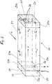
- Fig. 2 shows a modified embodiment of a flat tube evaporator tube 20 in a schematic representation, ie tubes and ribs are not shown, but essentially replaced by flow arrows.
- the flat tube evaporator 20 has - similar to the embodiment according to Fig. 1 - A horizontal flat tube bundle 21, which has a front tube bundle half 21 a and a rear tube bundle half 21 b. However, the air flowing through the flat tube evaporator 20 in the direction of the arrow L, but first meets the rear flat tube bundle half 21 b.
- On both sides of the flat tube bundle 21 collector boxes 22, 23 are arranged, in which open the flat tubes, not shown, of the bundle 21.
- the left in the drawing collection box 22 is divided by a continuous, vertically arranged partition wall 24 in a front chamber 22a and in a rear chamber 22b, wherein the front chamber 22a has an inlet opening 25 and the rear chamber 22b has an outlet opening 26 for the refrigerant , Inlet and outlet openings 25, 26 are thus both on the lower side of the flat tube evaporator 20, which is in the position as shown in the drawing, installed in the vehicle.
- the right in the drawing collection box 23 has a vertically arranged partition wall 27, which divides the collection box 23 into a front chamber 23 a and 23 b in a rear chamber.
- the partition wall 27 has in its upper region, preferably in its upper half, three overflow openings 28 which connect the two adjacent chambers 23a, 23b to one another (fewer or more openings are also possible).
- the flat tube evaporator 20 is traversed by double-flow of refrigerant, in the following manner: the refrigerant enters the direction of the arrow E via the opening 25 in the front chamber 22 a and then flows through the front tube bundle 21 a, the arrows V, in the Chamber 23a on the right side of the evaporator 20.
- the refrigerant enters the chamber 23a in a liquid state and partially becomes en route to the chamber 23a evaporates, that is, a portion of the inflowing into the chamber 23 a refrigerant is still liquid. Therefore, the overflow openings 28 are arranged in the upper portion of the partition wall 27, so that an overflow of liquid refrigerant from the front chamber 23 a into the rear chamber 23 b is prevented.
- refrigerant predominantly passes through the overflow openings 28 into the chamber 23b in the vapor state - here, in the direction of the arrow U, the deflection of the refrigerant takes place "in the depth", ie counter to the air flow direction L.
- the refrigerant then enters the chamber 23b the rear tube bundle 21 b and flows through this in the direction of arrow R until it enters the outlet chamber 22b. From there, the refrigerant exits in the vapor state through the outlet opening 26 in the lower region of the chamber 22 b from the flat tube evaporator 20.
- FIG. 2 A further, not shown embodiment of the flat tube evaporator is possible, with the top inlet E and outlet A (corresponding Fig. 2 ).
- the evaporator 20 according to Fig. 2 would be rotated about its longitudinal axis by 180 °, so that the inlet opening 25 and the outlet opening 26 would be at the top and the overflow openings 28 would come to lie in the lower half of the partition wall 27.
- the liquid refrigerant would then remain substantially at the bottom of the evaporator, so that only vaporous refrigerant would be sucked.
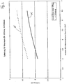
- Fig. 3 shows a performance comparison between conventional evaporator design with vertical tubes and inventive design with horizontal tubes.
- the performance of the evaporator is applied over the installed face including the collector - based on the FIGS. 1a and 2a
- the end face corresponds to the product B x H.
- the solid curve K clearly below the curve E, refers to evaporators of conventional construction, ie with vertical tubes, horizontally extending headers within a ratio of B to H of 2.9 to 5.4.
- the reduced power compared to the construction according to the invention results from a multiplicity of refrigerant deflections and the resulting refrigerant-side pressure drop.
- Fig. 4 shows another diagram in which the specific usable space, ie the ratio of usable space to installation space is plotted over the free end face (this is the product B 'x H, where B' is the width reduced by the height of the collecting boxes)
- the upper dashed curve E corresponds to the construction according to the invention
- the underlying horizontally extending curve K corresponds to the conventional construction with vertical tubes.
- Fig. 5 shows another diagram in which the air-side pressure drop across the evaporator is plotted over the total end face including the surface of the collector.
- the dashed line E again the inventive and the solid line K denotes the conventional Construction.
- the pressure drop for the invention is therefore much cheaper. This advantage in favor of the invention results in turn due to the lower proportions of the collecting boxes on the entire end face in the invention.
Landscapes
- Engineering & Computer Science (AREA)
- Physics & Mathematics (AREA)
- Thermal Sciences (AREA)
- Mechanical Engineering (AREA)
- General Engineering & Computer Science (AREA)
- Heat-Exchange Devices With Radiators And Conduit Assemblies (AREA)
- Air-Conditioning For Vehicles (AREA)
Description
- Die Erfindung betrifft einen Verdampfer einer Klimaanlage für ein Kraftfahrzeug nach Patentanspruch 1. Die heute üblichen Verdampfer wie Scheibenverdampfer und Flachrohrverdampfer werden senkrecht in die Klimaanlage bzw. das Fahrzeug eingebaut, d. h. mit senkrecht verlaufenden Rohren. Gängige Flachrohrverdampfer, z. B. bekannt durch die
DE-A 198 26 881 der Anmelderin, sind zweireihig ausgebildet, d. h. mit zwei Reihen von Flachrohren, die hintereinander bzw. nacheinander von Luft umströmt werden. Die Enden der Sammelrohre münden in Sammelkästen, die jeweils in zwei Kammern unterteilt sind, die die Enden der Flachrohre aufnehmen. Das Kältemittel wird bei zweiflutiger Durchströmung einmal in der Tiefe, d. h. entgegen der Luftströmungsrichtung umgelenkt. Derartige Flachrohrverdampfer weisen eine Höhe H, gemessen in Längsrichtung der Rohre, auf und eine Breite B, quer zur Rohrlängsrichtung gemessen. Das Produkt aus Höhe H und Breite B ergibt die Stirnfläche des Verdampfers. Das Kältemittel kann - zusätzlich zur Umlenkung in der Tiefe - auch in der Breite umgelenkt werden. Diese Verdampferbauweise weist bekanntermaßen ein Verhältnis von Höhe zu Breite von ca. 0,5 bis 2,0 auf, d. h. bei den niedrigsten Verdampfern dieser Bauart beträgt die Höhe ungefähr die Hälfte der Breite. - Das Dokument
US 4679410 offenbart die Merkmale des Oberbegriffs von Anspruch 1. Ähnliche Abmessungsverhältnisse von Höhe zu Breite liegen bei den Scheibenverdampfern vor, wie beispielsweise durch dieEP-A 1 089 046 bekannt. Bei dieser Bauweise sind die Strömungskanäle für das Kältemittel und die Sammelkammern in Scheibenhälften integriert, die miteinander verlötet werden. Auch diese Scheibenverdampfer werden mit senkrecht stehenden Strömungskanälen eingebaut. - Ein technisches Problem ergibt sich dann, wenn man aufgrund bestimmter Einbauforderungen des Fahrzeugherstellers das Verhältnis von Verdampferhöhe zu Verdampferbreite weiter verringern will, d. h. Verdampfer niedriger Höhe und relativ großer Breite benötigt. Der Anteil der Sammelkästen an der Stirnfläche würde diese überproportional reduzieren. Um eine gleichmäßige Temperaturverteilung am Luftaustritt eines solchen Verdampfers zu erhalten, müsste das Kältemittel mehrfach in der Breite umgelenkt werden, was zu erheblichem kältemittelseitigen Druckverlust führen würde. Daher sind dieser Bauart Grenzen bezüglich der Verringerung der Verdampferhöhe bei etwa gleicher Stirnfläche gesetzt. Gleiches gilt prinzipiell für die Scheibenverdampfer.
- Es ist Aufgabe der vorliegenden Erfindung, einen Verdampfer der eingangs genannten Art zu schaffen, der über eine geringere Bauhöhe bei gleich bleibender Stirnfläche und gleicher Leistung verfügt, möglichst bei günstigem Temperaturprofil.
- Die Lösung dieser Aufgabe ergibt sich aus den Merkmalen des Patentanspruches 1. Die Erfindung sieht einen liegenden Verdampfer vor, bei dem die Strömungskanäle in Einbaulage etwa horizontal und die seitlichen Sammelkammern etwa vertikal angeordnet bzw. durchströmt sind. Vertikal bedeutet jedoch nicht streng vertikal, da die Verdampfer in Klimaanlagen zum Teil auch etwas geneigt angeordnet werden. Eine solche Anordnung soll auch von dem Begriff etwa vertikal umfaßt sein. Durch diese Bauweise kann ein Verhältnis von Höhe zu Breite im Bereich von 1 : 3 bis 1 : 6 bzw. ein Verhältnis von Breite zu Höhe im Bereich von ca. 3 bis 6 und mehr, das heißt vorteilhaft auch bis 7, 8, 9m oder 10 oder mehr, realisiert werden, ohne dass die Leistung des Verdampfers abnimmt. Gegenüber der Bauweise mit senkrechten Strömungskanälen ergibt sich sogar ein Leistungsgewinn. Ferner ergibt sich gegenüber der bekannten Bauweise mit senkrechten Strömungskanälen der Vorteil einer geringeren Teilezahl, da der erfindungsgemäße Verdampfer längere, aber weniger Rohre bzw. Strömungskanäle aufweist. Dies reduziert somit die Fertigungskosten.
- Nach einer vorteilhaften Weiterbildung der Erfindung ist der Verdampfer als Scheiben- oder Flachrohrverdampfer ausgebildet, wobei sich der Flachrohrverdampfer als besonders vorteilhaft erweist. Er kann prinzipiell mit nahezu den gleichen oder ähnlichen Bauteilen wie beim eingangs erwähnten Stand der Technik der Anmelderin gebaut werden - allerdings in liegender Bauweise mit entsprechend niedriger Höhe und großer Breite. Durch Anordnung von Trennwänden in den Sammelkästen kann eine zwei- oder mehrfache Durchflutung mit Umlenkung des Kältemittels in der Tiefe und der Höhe ermöglicht werden, was eine günstige Temperaturverteilung für die aus dem Verdampfer austretende Luft bewirkt.
- In weiterer vorteilhafter Ausgestaltung der Erfindung erfolgt die Einspritzung des Kältemittels in die unten liegenden Rohre bzw. in den unten liegenden der Sammelkammer. Vorteilhafterweise wird das Kältemittel dann im oberen Bereich im dampfförmigen bzw. überhitzten Zustand abgesaugt. Damit ist es möglich, den erfindungsgemäßen Verdampfer auch mit einem herkömmlichen Expansionsventil zu betreiben.
- Gemäß einer vorteilhaften Weiterbildung der Erfindung können die Ein- und Austrittsöffnungen beide unten an einem Sammelkasten angeordnet sein, dann liegen die Überströmöffnungen für die Umlenkung des Kältemittels in der Tiefe im oberen Bereich der senkrechten Trennwand. Dadurch wird verhindert, dass flüssiges Kältemittel abgesaugt wird.
- In vorteilhafter Weiterbildung der Erfindung können die Ein- und Austrittsöffnungen beide oben an einem Sammelkasten angeordnet sein, dann liegen die Überströmöffnungen für die Umlenkung des Kältemittels in der Tiefe im unteren Bereich der senkrechten Trennwand. Dadurch wird erreicht, dass nur dampfförmiges Kältemittel abgesaugt wird.
- Nach der Erfindung weist der Verdampfer Seitenteile auf, wobei das unten liegende Seitenteil Aussparungen für den Kondensatablauf aufweist. Da die Flachrohre horizontal liegen, wird das sich bei feuchter Luft bildende Kondensat durch den Luftstrom mitgenommen. Zwischen den Flachrohrreihen kann es - der Schwerkraft folgend - nach unten abtropfen und durch die Aussparungen ablaufen. Damit wird unangenehmer Verdampfergeruch vermieden. Darüber hinaus können am luftaustrittsseitigen Stirnbereich des Verdampfers Spritzwassergitter zum Auffangen des abspritzenden Kondenswassers angeordnet sein.
- Dabei kann es vorteilhaft sein, daß über die Länge des Seitenteils betrachtet zumindest eine oder auch mehrere Aussparungen vorgesehen sind, wie beispielsweise eine Mehrzahl von länglichen Aussparungen. Dabei kann es zweckmäßig sein, wenn die Aussparungen im Seitenteil im Wesentlichen auf der Ab- bzw. auf der Ausströmseite angeordnet sind. Bei einem anderen Ausführungsbeispiel kann es auch zweckmäßig sein, wenn die Aussparung/die Aussparungen auf der Einströmseite liegen oder auch über beide Bereiche zumindest teilweise, also Ausströmseite oder An- oder Einströmseite, liegen.
- Ausführungsbeispiele der Erfindung sind in den Zeichnungen dargestellt und werden im Folgenden näher beschrieben. Es zeigen
- Fig. 1
- einen liegenden Verdampfer in zweiflutiger Durchströmung in Flachrohrbauweise in einer Ansicht von unten,
- Fig. 1a
- den Verdampfer gemäß
Fig. 1 in einer Ansicht von vorne, - Fig. 1b
- den Verdampfer gemäß
Fig. 1 in einer Seitenansicht, - Fig. 1c
- ein Ausführungsbeispiel eines Verdampfers in einer Ansicht von unten,
- Fig. 2
- ein zweites Ausführungsbeispiel eines liegenden Verdampfers mit zweifacher Durchflutung in schematischer Darstellung,
- Fig. 3
- ein Diagramm zum Leistungsvergleich der erfindungsgemäßen und der herkömmlichen Bauweise,
- Fig.4
- ein Diagramm zum Vergleich der erfindungsgemäßen und der herkömmlichen Bauweise im Hinblick auf den spezifischen Nutzraum und
- Fig. 5
- ein Diagramm zum Vergleich der erfindungsgemäßen und der herkömmlichen Bauweise im Hinblick auf den luftseitigen Druckabfall.
-
Fig. 1, 1 a und 1 b zeigen einen zweireihigen, zweiflutig durchströmten Flachrohrverdampfer 1 in liegender Einbaulage, das heißt mit liegenden Flachrohren, in einer Ansicht von unten. Die Luftströmungsrichtung ist durch den Pfeil L gekennzeichnet. -
Fig. 1a zeigt den Verdampfer 1 mit Blick auf seine Stirnfläche, die durch die Höhe H und die Breite B definiert ist. Die Stirnseite des Verdampfers 1 zeigt insgesamt zehn Flachrohre 2, zwischen denen Wellrippen 3 angeordnet sind. Die Flachrohre 2 münden zu beiden Seiten in Sammelkästen 4, 5, die jeweils durch eine Längstrennwand 6 in zwei Kammern 7, 8 unterteilt sind (die Unterteilung der Kammer 5 ist inFig. 1 und 1 a nicht erkennbar). Die erste Flachrohrreihe 9 mündet in die Kammer 7 und die gegenüberliegende (verdeckt), während die zweite Flachrohrreihe 10 (verdeckt), dargestellt durch Pfeile 10, in die Kammer 8 und die gegenüberliegende Kammer (verdeckt) mündet. Beiderseits der Flachrohre 2 sind Seitenteile 11, 12 angeordnet, die mit den benachbarten Wellrippen 3 und auch mit den Sammelkästen 4, 5 verlötet sind. Das in Einbaulage unten liegende Seitenteil 12 weist drei längliche Aussparungen 13 auf, die teilweise den Blick auf die erste Flachrohrreihe 9 freigeben. Diese Aussparungen 13 sind für den Ablauf von Kondensat, welches sich bei feuchter Luft auf der Verdampferoberfläche bildet, vorgesehen. Der Verdampfer 1 weist zwei Kältemittelanschlüsse, nämlich einen Kältemitteleintritt 14 und einen Kältemittelaustritt 15 auf, welche über eine Kältemittelzuleitung 16 und eine Kältemittelableitung 17 mit einem Expansionsventil 18 verbunden sind (Fig. 1b ). Die Einspritzung des Kältemittels erfolgt also an unterster Stelle des Verdampfers 1, und zunächst wird die in Luftströmungsrichtung (Pfeil L) hinten liegende Rohrreihe 10 von Kältemittel durchströmt. Das Kältemittel gelangt dann in die hinten liegende Kammer 8 des Sammelkastens 4. In der Trennwand 6 sind Durchtrittsöffnungen 19 angeordnet, durch die das Kältemittel in die in Luftströmungsrichtung vorne liegende Kammer 7 übertritt (Umlenkung in der Tiefe). Von dort gelangt es in die vordere Flachrohrreihe 9 und dann in den Sammelkasten 5, dessen hintere Kammer 5a und vordere Kammer 5b inFig. 1b erkennbar sind. Das Kältemittel wird im oberen Bereich der Kammer 5b über den Anschlussstutzen 15 abgesaugt. - Der Flachrohrverdampfer 1 wird - wie bereits erwähnt - liegend, also wie in der Zeichnung dargestellt, in die Klimaanlage des Kraftfahrzeuges eingebaut und von der abzukühlenden Luft in Richtung des Pfeils L angeströmt. Insofern ergibt sich für die Strömung zwischen Kältemittel und Luft ein Kreuzgegenstrom. Der Flachrohrverdampfer weist in dem dargestellten Ausführungsbeispiel eine Breite B von 500 mm auf, wobei diese Breite die beiden Sammelkästen 4, 5 mit einschließt. Die Höhe H des Verdampfers beträgt 120 mm. Daraus ergibt sich ein Verhältnis von Breite B zu Höhe H von 4,16.
- Verdampfer dieser Bauart weisen vorteilhafterweise Höhen im Bereich von H = 65 - 142 mm, vorzugsweise von H = 98 - 120 mm auf.
- Die
Figur 1c zeigt einen Verdampfer in einer Ansicht von unten, bei welchem bei gleichen Bauteilen auch die gleichen Bezugszeichen verwendet sind, wie inFigur 1 a. Bei derFigur 1c handelt es sich um ein Ausführungsbeispiel, bei welchem die Öffnungen 13' zum Kondensatablauf auf der anderen Seite im Vergleich zum Ausführungsbeispiel derFigur 1a angeordnet sind. Im Ausführungsbeispiel derFigur 1 a ist der Ablauf 13 für das Kondensat auf der Luftanströmseite im Seitenteil angeordnet, wohingegen im Ausführungsbeispiel derFigur 1c der Ablauf 13' auf der Abströmseite bzw. Ausströmseite im Seitenteil angeordnet ist. - Bei einem weiteren Ausführungsbeispiel kann der Ablauf für ein Kondensat, das auf der Oberfläche des Verdampfers kondensiert, auch sowohl auf der An- als auch auf der Abströmseite des Seitenteils liegen.
- Vorteilhaft sind die Aussparungen durch längliche Ausschnitte gebildet, sie können aber auch als runde Ausschnitte oder anderweitige Ausschnitte ausgebildet sein.
-
Fig. 2 zeigt ein abgewandeltes Ausführungsbeispiel eines Flachrohrrohrverdampfers 20 in schematischer Darstellung, d. h. Rohre und Rippen sind nicht dargestellt, sondern im Wesentlichen durch Strömungspfeile ersetzt. Der Flachrohrverdampfer 20 weist - ähnlich wie im Ausführungsbeispiel gemäßFig. 1 - ein liegendes Flachrohrbündel 21 auf, welches eine vordere Rohrbündelhälfte 21 a und eine hintere Rohrbündelhälfte 21 b aufweist. Die Luft, die den Flachrohrverdampfer 20 in Richtung des Pfeile L durchströmt, trifft allerdings zuerst auf die hintere Flachrohrbündelhälfte 21 b. Beiderseits des Flachrohrbündels 21 sind Sammelkästen 22, 23 angeordnet, in welche die nicht dargestellten Flachrohre des Bündel 21 münden. Der in der Zeichnung links gelegene Sammelkasten 22 ist durch eine durchgehende, senkrecht angeordnete Trennwand 24 in eine vordere Kammer 22a und in eine hintere Kammer 22b unterteilt, wobei die vordere Kammer 22a eine Eintrittsöffnung 25 und die hintere Kammer 22b eine Austrittsöffnung 26 für das Kältemittel aufweist. Ein- und Austrittsöffnung 25, 26 liegen also beide auf der unteren Seite des Flachrohrverdampfers 20, der in der Lage, wie sie in der Zeichnung dargestellt ist, im Fahrzeug eingebaut ist. Der in der Zeichnung rechts gelegene Sammelkasten 23 weist eine senkrecht angeordnete Trennwand 27 auf, die den Sammelkasten 23 in eine vordere Kammer 23a und in eine hintere Kammer 23b unterteilt. Die Trennwand 27 weist in ihrem oberen Bereich, vorzugsweise in ihrer oberen Hälfte drei Überströmöffnungen 28 auf, welche die beiden benachbarten Kammern 23a, 23b miteinander verbindet (weniger oder mehr Öffnungen sind ebenso möglich). - Der Flachrohrverdampfer 20 wird zweiflutig von Kältemittel durchströmt, und zwar in folgender Weise: das Kältemittel tritt in Richtung des Pfeils E über die Öffnung 25 in die vordere Kammer 22a ein und strömt dann durch das vordere Rohrbündel 21 a, den Pfeilen V folgend, in die Kammer 23a auf der rechten Seite des Verdampfers 20. Das Kältemittel tritt in flüssigem Zustand in die Kammer 23a ein und wird auf dem Wege zur Kammer 23a teilweise verdampft, d. h. ein Teil des in die Kammer 23a einströmenden Kältemittels ist noch flüssig. Daher sind die Überströmöffnungen 28 im oberen Bereich der Trennwand 27 angeordnet, so dass ein Überströmen von flüssigem Kältemittel von der vorderen Kammer 23a in die hintere Kammer 23b verhindert wird. Durch die Überströmöffnungen 28 tritt somit vorwiegend Kältemittel in dampfförmigem Zustand in die Kammer 23b über - hier erfolgt also in Richtung des Pfeils U die Umlenkung des Kältemittels "in der Tiefe", d. h. entgegen der Luftströmungsrichtung L. Aus der Kammer 23b tritt das Kältemittel dann in das hintere Rohrbündel 21 b ein und durchströmt dieses in Richtung des Pfeils R, bis es in die Austrittskammer 22b gelangt. Von dort tritt das Kältemittel in dampfförmigem Zustand durch die Austrittsöffnung 26 im unteren Bereich der Kammer 22b aus dem Flachrohrverdampfer 20 aus.
- Durch diese Anordnung, d. h. die in der Trennwand 27 oben angeordneten Überströmöffnungen 28 bei unten liegendem Ein- und Auslass E, A wird erreicht, dass nur dampfförmiges Kältemittel abgesaugt wird und somit eine Regelung über ein herkömmliches Expansionsventil möglich ist.
- Eine weitere, hier nicht dargestellte Ausführungsform des Flachrohrverdampfers ist möglich, und zwar mit oben liegendem Einlass E und Auslass A (entsprechend
Fig. 2 ). Der Verdampfer 20 gemäßFig. 2 wäre um seine Längsachse um 180° zu drehen, so dass die Eintrittsöffnung 25 und die Austrittsöffnung 26 oben lägen und die Überströmöffnungen 28 in der unteren Hälfte der Trennwand 27 zu liegen kämen. Das flüssige Kältemittel würde dann im Wesentlichen im unteren Bereich des Verdampfers bleiben, so dass nur dampfförmiges Kältemittel abgesaugt würde. - Die aus dem Flachrohrverdampfer austretende Luft führt einen Teil des Kondensats, welches sich auf der Verdampferoberfläche bildet, mit sich, was zu unerwünschtem Spritzwasser führen würde. Aus diesem Grunde ist es vorteilhaft, wenn in Luftströmungsrichtung L hinter dem Verdampfer ein an sich bekanntes, hier nicht dargestelltes Spritzwassergitter angeordnet wäre, welches das Spritzwasser auffängt und nach unten ableitet bzw. abtropfen lässt.
-
Fig. 3 zeigt einen Leistungsvergleich zwischen konventioneller Verdampferbauweise mit senkrechten Rohren und erfindungsgemäßer Bauweise mit liegenden Rohren. Dabei ist die Leistung des Verdampfers aufgetragen über der verbauten Stirnfläche einschließlich der Sammler - bezogen auf dieFiguren 1a und2a entspricht die Stirnfläche also dem Produkt B x H. Die gestrichelte Linie E zeigt die Leistung für die erfindungsgemäße Bauweise für Stirnflächen von 4 bis 6,5 qdm bei gleich bleibender Höhe von H = 120 mm, beginnend mit einer Breite von B = 350 mm (entsprechend einer Stirnfläche von 4,2 qdm). Dies entspricht einem Verhältnis B zu H von 2,9. Der Stirnfläche von 6,5 qdm entspricht eine Breite von B = 540 mm, was ein Verhältnis von B zu H gleich 4,5 bedeutet. Die durchgezogene Kurve K, die deutlich unter der Kurve E liegt, bezieht sich auf Verdampfer in konventioneller Bauweise, d. h. mit senkrecht verlaufenden Rohren, waagerecht verlaufenden Sammelkästen innerhalb eines Verhältnisses von B zu H von 2,9 bis 5,4. Die Minderleistung gegenüber der erfindungsgemäßen Bauweise ergibt sich aus einer Vielzahl von Kältemittelumlenkungen und dem daraus resultierenden kältemittelseitigen Druckabfall. -
Fig. 4 zeigt ein weiteres Diagramm, bei dem der spezifische Nutzraum, d. h. das Verhältnis von Nutzraum zu Bauraum aufgetragen ist über der freien Stirnfläche (hierbei handelt es sich um das Produkt B' x H, wobei B' die um die Höhe der Sammelkästen reduzierte Breite ist). Die obere gestrichelte Kurve E entspricht der erfindungsgemäßen Bauweise, während die darunter liegende waagerecht verlaufende Kurve K der konventionellen Bauweise mit senkrechten Rohren entspricht. Es ist ohne weiteres ersichtlich, dass die erfindungsgemäße Bauweise mit liegenden Rohren eine relativ größere freie Stirnfläche bietet, weil der Anteil der Sammelkästen an der gesamten Stirnfläche wesentlich geringer ist, als dies bei der konventionellen Bauweise bei einem derartigen Verhältnis von Breite zu Höhe der Fall ist. -
Fig. 5 zeigt ein weiteres Diagramm, bei dem der luftseitige Druckabfall am Verdampfer aufgetragen ist über der Gesamtstirnfläche einschließlich der Fläche der Sammler. Auch hier bezeichnet die gestrichelte Linie E wieder die erfindungsgemäße und die durchgezogene Linie K die konventionelle Bauweise. Der Druckabfall für die Erfindung fällt also wesentlich günstiger aus. Dieser Vorteil zu Gunsten der Erfindung ergibt sich wiederum aufgrund der geringeren Anteile der Sammelkästen an der Gesamtstirnfläche bei der Erfindung.
Claims (9)
- Verdampfer für Klimaanlagen von Kraftfahrzeugen, bestehend aus parallel verlaufenden, ein Kältemittel führenden Strömungskanälen, aus von Luft beaufschlagten zwischen den Strömungskanälen angeordneten Rippen sowie aus mindestens einer Sammelkammer mit Kältemitteleintritts- und/oder -austrittsöffnungen, wobei der Verdampfer einen Block mit einer in der Senkrechten gemessenen Höhe H und einer in der Horizontalen gemessenen Breite B aufweist, deren Produkt H x B die Stirnfläche des Verdampfers ergibt, wobei die Strömungskanäle in Einbaulage liegend, d. h. im Wesentlichen horizontal und die Sammelkammer/n in senkrechter Richtung durchströmbar angeordnet sind, dadurch gekennzeichnet, dass das Verhältnis V von Breite B zu Höhe H folgenden Bereich aufweist:

die Strömungskanäle als Flachrohre (2) und die Sammeikammern als Sammelkästen (4, 5; 22, 23), in welche die Flachrohre (2) münden, ausgebildet sind, mit zwei Reihen (9, 10) von Flachrohren (2) und beiderseits der Flachrohrenden angeordnete Sammelkästen (4, 5), die jeweils in zwei Kammern (7, 8; 5a, 5b) für jede Flachrohrreihe (9, 10) unterteilt sind, wobei beiderseits der Flachrohrreihen (9, 10) Seitenteile (11, 12) angeordnet sind, wobei das unten liegende Seitenteil (12) Aussparungen (13) für den Ablauf von Kondensat aufweist. - Verdampfer nach Anspruch 1, dadurch gekennzeichnet, dass die Kältemitteleintrittsöffnung (14) im unteren Bereich einer Kammer (5a) eines Sammelkastens (5) angeordnet ist.
- Verdampfer nach Anspruch 1 oder 2, dadurch gekennzeichnet, dass die Kältemittelautrittsöffnung (15) im oberen Bereich einer Kammer (5b) eines Sammelkastens (5) angeordnet ist.
- Verdampfer nach Anspruch 2 oder 3, dadurch gekennzeichnet, dass Kältemittelein- und -austrittsöffnungen (14, 15) an demselben Sammelkasten (5) angeordnet sind.
- Verdampfer nach einem der Ansprüche 1 bis 4, gekennzeichnet durch eine zweifache Durchflutung (V, R) mit einer Umlenkung U des Kältemittels in der Tiefe, d. h. entgegen der Luftströmungsrichtung L.
- Verdampfer nach Anspruch 4 oder 5, dadurch gekennzeichnet, dass Kältemitteleintritts- und -austrittsöffnungen (25, 26) im unteren Bereich eines Sammelkastens (22) angeordnet sind und dass der andere Sammelkasten (23) eine senkrechte Trennwand (27) mit Überströmöffnungen (28) aufweist, die im oberen Bereich angeordnet sind.
- Verdampfer nach Anspruch 4 oder 5, dadurch gekennzeichnet, dass die Kältemitteleintritts- und -austrittsöffnungen im oberen Bereich eines Sammelkastens angeordnet sind und dass der andere Sammelkasten eine senkrechte Trennwand mit Überströmöffnungen aufweist, die im unteren Bereich angeordnet sind.
- Verdampfer nach einem der vorhergehenden Ansprüche, dadurch gekennzeichnet, dass Aussparungen für den Kondensatablauf bevorzugt im Seitenteil auf der Luftausströmseite angeordnet sind.
- Verdampfer nach einem der vorhergehenden Ansprüche, dadurch gekennzeichnet, dass Aussparungen für den Kondensatablauf bevorzugt im Seitenteil auf der Luftanströmseite angeordnet sind.
Applications Claiming Priority (2)
| Application Number | Priority Date | Filing Date | Title |
|---|---|---|---|
| DE2002131918 DE10231918A1 (de) | 2002-07-15 | 2002-07-15 | Verdampfer für Kfz-Klimaanlagen |
| DE10231918 | 2002-07-15 |
Publications (2)
| Publication Number | Publication Date |
|---|---|
| EP1382926A1 EP1382926A1 (de) | 2004-01-21 |
| EP1382926B1 true EP1382926B1 (de) | 2017-05-10 |
Family
ID=29761971
Family Applications (1)
| Application Number | Title | Priority Date | Filing Date |
|---|---|---|---|
| EP03015967.7A Expired - Lifetime EP1382926B1 (de) | 2002-07-15 | 2003-07-14 | Verdampfer für Kfz-Klimaanlagen |
Country Status (2)
| Country | Link |
|---|---|
| EP (1) | EP1382926B1 (de) |
| DE (1) | DE10231918A1 (de) |
Families Citing this family (1)
| Publication number | Priority date | Publication date | Assignee | Title |
|---|---|---|---|---|
| CN114963796B (zh) * | 2022-06-29 | 2025-12-02 | 天津三电汽车空调有限公司 | 一种换热器用耐高压气室结构及耐高压换热器 |
Citations (1)
| Publication number | Priority date | Publication date | Assignee | Title |
|---|---|---|---|---|
| US4679410A (en) * | 1986-10-30 | 1987-07-14 | General Motors Corporation | Integral evaporator and accumulator for air conditioning system |
Family Cites Families (4)
| Publication number | Priority date | Publication date | Assignee | Title |
|---|---|---|---|---|
| DE4220823C2 (de) * | 1992-06-25 | 1996-08-29 | Thermal Waerme Kaelte Klima | Heizungswärmetauscher für Personenkraftwagen mit mindestens zwei Teilwärmetauschern |
| JPH116693A (ja) * | 1997-04-23 | 1999-01-12 | Denso Corp | 車両空調用熱交換器 |
| DE19826881B4 (de) * | 1998-06-17 | 2008-01-03 | Behr Gmbh & Co. Kg | Wärmeübertrager, insbesondere Verdampfer |
| AU2002351617A1 (en) * | 2001-12-27 | 2003-07-15 | Dana Canada Corporation | Heat exchanger with internal slotted manifold |
-
2002
- 2002-07-15 DE DE2002131918 patent/DE10231918A1/de not_active Withdrawn
-
2003
- 2003-07-14 EP EP03015967.7A patent/EP1382926B1/de not_active Expired - Lifetime
Patent Citations (1)
| Publication number | Priority date | Publication date | Assignee | Title |
|---|---|---|---|---|
| US4679410A (en) * | 1986-10-30 | 1987-07-14 | General Motors Corporation | Integral evaporator and accumulator for air conditioning system |
Also Published As
| Publication number | Publication date |
|---|---|
| DE10231918A1 (de) | 2004-01-29 |
| EP1382926A1 (de) | 2004-01-21 |
Similar Documents
| Publication | Publication Date | Title |
|---|---|---|
| DE69219107T2 (de) | Verdampfer | |
| DE19719252C2 (de) | Zweiflutiger und in Luftrichtung einreihiger hartverlöteter Flachrohrverdampfer für eine Kraftfahrzeugklimaanlage | |
| DE60116922T2 (de) | Kondensator | |
| DE19719251A1 (de) | Verteil-/Sammel-Kasten eines mindestens zweiflutigen Verdampfers einer Kraftfahrzeugklimaanlage | |
| DE10314782A1 (de) | Wärmetauscher für den Wärmeaustausch zwischen einem inneren und einem äußeren Fluid und Verfahren zur Herstellung desselben | |
| DE102009034352A1 (de) | Wärmetauscher | |
| WO2005088219A1 (de) | Wärmetauscher einer fahrzeugklimaanlage | |
| EP0929784B1 (de) | Flachrohrwärmetauscher für kraftfahrzeuge mit an krägen eines rohrbodens gehaltenen flachrohren | |
| EP2232183A2 (de) | Wärmeübertrager, insbesondere heizkörper für kraftfahrzeuge | |
| DE69500676T2 (de) | Wärmetauscher | |
| EP1203922A2 (de) | Kondensator und Rohr dafür | |
| EP1411310B1 (de) | Wärmeübertrager in Serpentinenbauweise | |
| DE10257767A1 (de) | Wärmeübertrager | |
| DE19719257A1 (de) | Sammelkasten eines Verdampfers in Flachrohr- oder Plattenbauweise für eine Kraftfahrzeugklimaanlage und Herstellungsverfahren | |
| DE19957945B4 (de) | Kondensator mit Unterkühlstrecke | |
| EP1798506B1 (de) | Verdampfer | |
| DE19719261C2 (de) | Zweiflutiger Flachrohrverdampfer einer Kraftfahrzeugklimaanlage | |
| DE4213509A1 (de) | Wärmetauscher, insbesondere Kondensator für Fahrzeug-Klimaanlagen | |
| EP1712868B1 (de) | Wärmeübertrager | |
| EP0910778B1 (de) | Flachrohrverdampfer mit vertikaler längserstreckungsrichtung der flachrohre bei kraftfahrzeugen | |
| EP1717530B1 (de) | Wärmeübertrager, insbesondere Heckverdampfer für ein Kraftfahrzeug | |
| EP1816426B1 (de) | Wärmeübertrageranordnung, insbesondere eines Heckverdampfers in einem Kraftfahrzeug | |
| EP1934545B1 (de) | Heizkörper, kühlkreislauf, klimagerät für eine kraftfahrzeug-klimaanlage sowie klimaanlage für ein kraftfahrzeug | |
| EP1382926A1 (de) | Verdampfer für Kfz-Klimaanlagen | |
| DE10115513A1 (de) | Wärmeübertrager |
Legal Events
| Date | Code | Title | Description |
|---|---|---|---|
| PUAI | Public reference made under article 153(3) epc to a published international application that has entered the european phase |
Free format text: ORIGINAL CODE: 0009012 |
|
| AK | Designated contracting states |
Kind code of ref document: A1 Designated state(s): AT BE BG CH CY CZ DE DK EE ES FI FR GB GR HU IE IT LI LU MC NL PT RO SE SI SK TR |
|
| AX | Request for extension of the european patent |
Extension state: AL LT LV MK |
|
| 17P | Request for examination filed |
Effective date: 20040721 |
|
| AKX | Designation fees paid |
Designated state(s): AT BE BG CH CY CZ DE DK EE ES FI FR GB GR HU IE IT LI LU MC NL PT RO SE SI SK TR |
|
| RAP1 | Party data changed (applicant data changed or rights of an application transferred) |
Owner name: BEHR GMBH & CO. KG |
|
| 17Q | First examination report despatched |
Effective date: 20101102 |
|
| RAP1 | Party data changed (applicant data changed or rights of an application transferred) |
Owner name: MAHLE BEHR GMBH & CO. KG |
|
| GRAP | Despatch of communication of intention to grant a patent |
Free format text: ORIGINAL CODE: EPIDOSNIGR1 |
|
| INTG | Intention to grant announced |
Effective date: 20161104 |
|
| GRAS | Grant fee paid |
Free format text: ORIGINAL CODE: EPIDOSNIGR3 |
|
| GRAJ | Information related to disapproval of communication of intention to grant by the applicant or resumption of examination proceedings by the epo deleted |
Free format text: ORIGINAL CODE: EPIDOSDIGR1 |
|
| GRAL | Information related to payment of fee for publishing/printing deleted |
Free format text: ORIGINAL CODE: EPIDOSDIGR3 |
|
| GRAR | Information related to intention to grant a patent recorded |
Free format text: ORIGINAL CODE: EPIDOSNIGR71 |
|
| GRAA | (expected) grant |
Free format text: ORIGINAL CODE: 0009210 |
|
| INTC | Intention to grant announced (deleted) | ||
| RIN1 | Information on inventor provided before grant (corrected) |
Inventor name: JUNG, MATTHIAS Inventor name: DUERR, GOTTFRIED Inventor name: SEEWALD, WOLFGANG |
|
| INTG | Intention to grant announced |
Effective date: 20170328 |
|
| AK | Designated contracting states |
Kind code of ref document: B1 Designated state(s): AT BE BG CH CY CZ DE DK EE ES FI FR GB GR HU IE IT LI LU MC NL PT RO SE SI SK TR |
|
| REG | Reference to a national code |
Ref country code: GB Ref legal event code: FG4D Free format text: NOT ENGLISH |
|
| REG | Reference to a national code |
Ref country code: AT Ref legal event code: REF Ref document number: 892807 Country of ref document: AT Kind code of ref document: T Effective date: 20170515 Ref country code: CH Ref legal event code: EP |
|
| REG | Reference to a national code |
Ref country code: IE Ref legal event code: FG4D Free format text: LANGUAGE OF EP DOCUMENT: GERMAN |
|
| REG | Reference to a national code |
Ref country code: DE Ref legal event code: R096 Ref document number: 50315655 Country of ref document: DE |
|
| REG | Reference to a national code |
Ref country code: FR Ref legal event code: PLFP Year of fee payment: 15 |
|
| REG | Reference to a national code |
Ref country code: NL Ref legal event code: MP Effective date: 20170510 |
|
| PG25 | Lapsed in a contracting state [announced via postgrant information from national office to epo] |
Ref country code: FI Free format text: LAPSE BECAUSE OF FAILURE TO SUBMIT A TRANSLATION OF THE DESCRIPTION OR TO PAY THE FEE WITHIN THE PRESCRIBED TIME-LIMIT Effective date: 20170510 Ref country code: ES Free format text: LAPSE BECAUSE OF FAILURE TO SUBMIT A TRANSLATION OF THE DESCRIPTION OR TO PAY THE FEE WITHIN THE PRESCRIBED TIME-LIMIT Effective date: 20170510 Ref country code: GR Free format text: LAPSE BECAUSE OF FAILURE TO SUBMIT A TRANSLATION OF THE DESCRIPTION OR TO PAY THE FEE WITHIN THE PRESCRIBED TIME-LIMIT Effective date: 20170811 |
|
| PG25 | Lapsed in a contracting state [announced via postgrant information from national office to epo] |
Ref country code: BG Free format text: LAPSE BECAUSE OF FAILURE TO SUBMIT A TRANSLATION OF THE DESCRIPTION OR TO PAY THE FEE WITHIN THE PRESCRIBED TIME-LIMIT Effective date: 20170810 Ref country code: NL Free format text: LAPSE BECAUSE OF FAILURE TO SUBMIT A TRANSLATION OF THE DESCRIPTION OR TO PAY THE FEE WITHIN THE PRESCRIBED TIME-LIMIT Effective date: 20170510 Ref country code: SE Free format text: LAPSE BECAUSE OF FAILURE TO SUBMIT A TRANSLATION OF THE DESCRIPTION OR TO PAY THE FEE WITHIN THE PRESCRIBED TIME-LIMIT Effective date: 20170510 |
|
| PG25 | Lapsed in a contracting state [announced via postgrant information from national office to epo] |
Ref country code: RO Free format text: LAPSE BECAUSE OF FAILURE TO SUBMIT A TRANSLATION OF THE DESCRIPTION OR TO PAY THE FEE WITHIN THE PRESCRIBED TIME-LIMIT Effective date: 20170510 Ref country code: EE Free format text: LAPSE BECAUSE OF FAILURE TO SUBMIT A TRANSLATION OF THE DESCRIPTION OR TO PAY THE FEE WITHIN THE PRESCRIBED TIME-LIMIT Effective date: 20170510 Ref country code: SK Free format text: LAPSE BECAUSE OF FAILURE TO SUBMIT A TRANSLATION OF THE DESCRIPTION OR TO PAY THE FEE WITHIN THE PRESCRIBED TIME-LIMIT Effective date: 20170510 Ref country code: DK Free format text: LAPSE BECAUSE OF FAILURE TO SUBMIT A TRANSLATION OF THE DESCRIPTION OR TO PAY THE FEE WITHIN THE PRESCRIBED TIME-LIMIT Effective date: 20170510 Ref country code: CZ Free format text: LAPSE BECAUSE OF FAILURE TO SUBMIT A TRANSLATION OF THE DESCRIPTION OR TO PAY THE FEE WITHIN THE PRESCRIBED TIME-LIMIT Effective date: 20170510 |
|
| REG | Reference to a national code |
Ref country code: DE Ref legal event code: R097 Ref document number: 50315655 Country of ref document: DE |
|
| PG25 | Lapsed in a contracting state [announced via postgrant information from national office to epo] |
Ref country code: IT Free format text: LAPSE BECAUSE OF FAILURE TO SUBMIT A TRANSLATION OF THE DESCRIPTION OR TO PAY THE FEE WITHIN THE PRESCRIBED TIME-LIMIT Effective date: 20170510 |
|
| REG | Reference to a national code |
Ref country code: CH Ref legal event code: PL |
|
| PLBE | No opposition filed within time limit |
Free format text: ORIGINAL CODE: 0009261 |
|
| STAA | Information on the status of an ep patent application or granted ep patent |
Free format text: STATUS: NO OPPOSITION FILED WITHIN TIME LIMIT |
|
| 26N | No opposition filed |
Effective date: 20180213 |
|
| REG | Reference to a national code |
Ref country code: IE Ref legal event code: MM4A |
|
| GBPC | Gb: european patent ceased through non-payment of renewal fee |
Effective date: 20170810 |
|
| PG25 | Lapsed in a contracting state [announced via postgrant information from national office to epo] |
Ref country code: CH Free format text: LAPSE BECAUSE OF NON-PAYMENT OF DUE FEES Effective date: 20170731 Ref country code: IE Free format text: LAPSE BECAUSE OF NON-PAYMENT OF DUE FEES Effective date: 20170714 Ref country code: LI Free format text: LAPSE BECAUSE OF NON-PAYMENT OF DUE FEES Effective date: 20170731 |
|
| PG25 | Lapsed in a contracting state [announced via postgrant information from national office to epo] |
Ref country code: SI Free format text: LAPSE BECAUSE OF FAILURE TO SUBMIT A TRANSLATION OF THE DESCRIPTION OR TO PAY THE FEE WITHIN THE PRESCRIBED TIME-LIMIT Effective date: 20170510 |
|
| REG | Reference to a national code |
Ref country code: BE Ref legal event code: MM Effective date: 20170731 |
|
| PG25 | Lapsed in a contracting state [announced via postgrant information from national office to epo] |
Ref country code: LU Free format text: LAPSE BECAUSE OF NON-PAYMENT OF DUE FEES Effective date: 20170714 |
|
| REG | Reference to a national code |
Ref country code: FR Ref legal event code: PLFP Year of fee payment: 16 |
|
| PG25 | Lapsed in a contracting state [announced via postgrant information from national office to epo] |
Ref country code: GB Free format text: LAPSE BECAUSE OF NON-PAYMENT OF DUE FEES Effective date: 20170810 |
|
| PG25 | Lapsed in a contracting state [announced via postgrant information from national office to epo] |
Ref country code: BE Free format text: LAPSE BECAUSE OF NON-PAYMENT OF DUE FEES Effective date: 20170731 |
|
| REG | Reference to a national code |
Ref country code: AT Ref legal event code: MM01 Ref document number: 892807 Country of ref document: AT Kind code of ref document: T Effective date: 20170714 |
|
| PGFP | Annual fee paid to national office [announced via postgrant information from national office to epo] |
Ref country code: DE Payment date: 20180730 Year of fee payment: 16 Ref country code: FR Payment date: 20180724 Year of fee payment: 16 |
|
| PG25 | Lapsed in a contracting state [announced via postgrant information from national office to epo] |
Ref country code: AT Free format text: LAPSE BECAUSE OF NON-PAYMENT OF DUE FEES Effective date: 20170714 |
|
| PG25 | Lapsed in a contracting state [announced via postgrant information from national office to epo] |
Ref country code: HU Free format text: LAPSE BECAUSE OF FAILURE TO SUBMIT A TRANSLATION OF THE DESCRIPTION OR TO PAY THE FEE WITHIN THE PRESCRIBED TIME-LIMIT; INVALID AB INITIO Effective date: 20030714 Ref country code: MC Free format text: LAPSE BECAUSE OF FAILURE TO SUBMIT A TRANSLATION OF THE DESCRIPTION OR TO PAY THE FEE WITHIN THE PRESCRIBED TIME-LIMIT Effective date: 20170510 |
|
| PG25 | Lapsed in a contracting state [announced via postgrant information from national office to epo] |
Ref country code: CY Free format text: LAPSE BECAUSE OF NON-PAYMENT OF DUE FEES Effective date: 20170510 |
|
| REG | Reference to a national code |
Ref country code: DE Ref legal event code: R119 Ref document number: 50315655 Country of ref document: DE |
|
| PG25 | Lapsed in a contracting state [announced via postgrant information from national office to epo] |
Ref country code: TR Free format text: LAPSE BECAUSE OF FAILURE TO SUBMIT A TRANSLATION OF THE DESCRIPTION OR TO PAY THE FEE WITHIN THE PRESCRIBED TIME-LIMIT Effective date: 20170510 |
|
| PG25 | Lapsed in a contracting state [announced via postgrant information from national office to epo] |
Ref country code: DE Free format text: LAPSE BECAUSE OF NON-PAYMENT OF DUE FEES Effective date: 20200201 |
|
| PG25 | Lapsed in a contracting state [announced via postgrant information from national office to epo] |
Ref country code: PT Free format text: LAPSE BECAUSE OF FAILURE TO SUBMIT A TRANSLATION OF THE DESCRIPTION OR TO PAY THE FEE WITHIN THE PRESCRIBED TIME-LIMIT Effective date: 20170510 |
|
| PG25 | Lapsed in a contracting state [announced via postgrant information from national office to epo] |
Ref country code: FR Free format text: LAPSE BECAUSE OF NON-PAYMENT OF DUE FEES Effective date: 20190731 |