EP1382888A2 - Toroidal type continuously variable transmission - Google Patents
Toroidal type continuously variable transmission Download PDFInfo
- Publication number
- EP1382888A2 EP1382888A2 EP03016325A EP03016325A EP1382888A2 EP 1382888 A2 EP1382888 A2 EP 1382888A2 EP 03016325 A EP03016325 A EP 03016325A EP 03016325 A EP03016325 A EP 03016325A EP 1382888 A2 EP1382888 A2 EP 1382888A2
- Authority
- EP
- European Patent Office
- Prior art keywords
- line pressure
- oil pump
- reverse
- speed control
- continuously variable
- Prior art date
- Legal status (The legal status is an assumption and is not a legal conclusion. Google has not performed a legal analysis and makes no representation as to the accuracy of the status listed.)
- Withdrawn
Links
- 230000005540 biological transmission Effects 0.000 title claims abstract description 74
- 230000008859 change Effects 0.000 claims abstract description 78
- 230000007246 mechanism Effects 0.000 claims abstract description 29
- 230000007935 neutral effect Effects 0.000 claims description 22
- 230000001939 inductive effect Effects 0.000 claims description 4
- 230000008713 feedback mechanism Effects 0.000 claims description 2
- 230000000994 depressogenic effect Effects 0.000 description 6
- 238000005461 lubrication Methods 0.000 description 4
- 230000000903 blocking effect Effects 0.000 description 3
- 230000009467 reduction Effects 0.000 description 2
- 230000004044 response Effects 0.000 description 2
- 230000001360 synchronised effect Effects 0.000 description 2
- 238000010276 construction Methods 0.000 description 1
- 238000003944 fast scan cyclic voltammetry Methods 0.000 description 1
- 239000012530 fluid Substances 0.000 description 1
- 230000001050 lubricating effect Effects 0.000 description 1
- 230000004048 modification Effects 0.000 description 1
- 238000012986 modification Methods 0.000 description 1
- 238000010008 shearing Methods 0.000 description 1
- 238000011144 upstream manufacturing Methods 0.000 description 1
Images


Classifications
-
- F—MECHANICAL ENGINEERING; LIGHTING; HEATING; WEAPONS; BLASTING
- F16—ENGINEERING ELEMENTS AND UNITS; GENERAL MEASURES FOR PRODUCING AND MAINTAINING EFFECTIVE FUNCTIONING OF MACHINES OR INSTALLATIONS; THERMAL INSULATION IN GENERAL
- F16H—GEARING
- F16H61/00—Control functions within control units of change-speed- or reversing-gearings for conveying rotary motion ; Control of exclusively fluid gearing, friction gearing, gearings with endless flexible members or other particular types of gearing
- F16H61/66—Control functions within control units of change-speed- or reversing-gearings for conveying rotary motion ; Control of exclusively fluid gearing, friction gearing, gearings with endless flexible members or other particular types of gearing specially adapted for continuously variable gearings
- F16H61/664—Friction gearings
- F16H61/6648—Friction gearings controlling of shifting being influenced by a signal derived from the engine and the main coupling
-
- F—MECHANICAL ENGINEERING; LIGHTING; HEATING; WEAPONS; BLASTING
- F16—ENGINEERING ELEMENTS AND UNITS; GENERAL MEASURES FOR PRODUCING AND MAINTAINING EFFECTIVE FUNCTIONING OF MACHINES OR INSTALLATIONS; THERMAL INSULATION IN GENERAL
- F16H—GEARING
- F16H61/00—Control functions within control units of change-speed- or reversing-gearings for conveying rotary motion ; Control of exclusively fluid gearing, friction gearing, gearings with endless flexible members or other particular types of gearing
- F16H61/66—Control functions within control units of change-speed- or reversing-gearings for conveying rotary motion ; Control of exclusively fluid gearing, friction gearing, gearings with endless flexible members or other particular types of gearing specially adapted for continuously variable gearings
- F16H61/664—Friction gearings
- F16H61/6649—Friction gearings characterised by the means for controlling the torque transmitting capability of the gearing
Definitions
- the present invention relates in general to continuously variable transmissions, and more particularly, to toroidal type continuously variable transmissions for wheeled motor vehicles.
- a toroidal type continuously variable transmission for use with a wheeled motor vehicle comprises generally an input disc which receives a torque from an engine, an output disc which is coaxially arranged with the input disc and constantly engaged with driven road wheels to drive the same, power rollers which are each interposed between the input and output discs to transmit power therebetween by shearing oil film, and trunnions which rotatably support the power rollers.
- an oil pump which is constantly driven by the engine, a forward speed control valve which is used under forward movement of the vehicle, a reverse speed control valve which is used under reverse movement of the vehicle, and a hydraulic servo mechanism which moves each trunnion in a manner to pivot the power roller between a neutral position where a rotation axis of the power roller intersects a common axis of the input and output discs and an offset position where the rotation axis of the power roller is offset toward a shaft axis of the corresponding trunnion.
- a hydraulic pressure from the oil pump is directed to the hydraulic servo mechanism under control of the forward speed control valve, so that a controlled hydraulic pressure drives servo pistons of the hydraulic servo mechanism for moving the trunnions to pivot each power roller to a desired angled position.
- the power rollers are each applied, from the input and output discs, with a component force around the shaft axis of the corresponding trunnion, and thus, each power roller is forced to make a self-inclination around a shaft axis of the trunnion while continuously changing the radius of a circular arc described by the power roller and each of the input and output discs at their contacting portions. With this, a continuously variable speed change is carried out by the transmission.
- each power roller when the output disc is fed with the torque from the driven road wheels, each power roller is compelled to receive a component force in a direction of the trunnion shaft axis from the contact portion with the input disc using a certain friction on the input disc as a so-called reaction force receiver, and thus each power roller becomes offset in the direction of the trunnion shaft axis and due to the above-mentioned self-inclination of the power roller, a speed change ratio for a higher speed side is set in the transmission.
- this phenomenon brings about a lack of torque directed to the driven road wheels at a subsequent starting of the vehicle and thus smoothed starting of the vehicle is not obtained.
- a toroidal type continuously variable transmission in which when, with the engine kept stopped, the driven road wheels are rotated due to a traction of the vehicle or the like, an extra oil pump is driven by the driven road wheels for operating the hydraulic servo mechanism in a manner to suppress the above-mentioned undesired up-shifting movement in the transmission.
- a toroidal type continuously variable transmission which comprises an input disc adapted to be driven by a prime mover of a motor vehicle; an output disc coaxially arranged with the input disc, the output disc being adapted to be constantly connected to road wheels of the vehicle; power rollers each being interposed between the input and output discs to transmit a torque from the input disc to the output disc through the power rollers; trunnions rotatably supporting the power rollers respectively; a main oil pump powered by the prime mover; a line pressure producing circuit which produces a line pressure by adjusting an oil pressure produced by the main oil pump; a hydraulic servo mechanism powered by the main oil pump, the hydraulic servo mechanism inducing a speed change between the input and output discs by actuating the trunnions in such a manner as to pivot a rotation axis of each power roller between a neutral position where the rotation axis intersects a common axis of the input and output discs at right angles and an offset position where the rotation
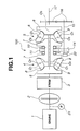
- FIGs. 1 to 4 there is shown a toroidal type continuously variable transmission of a first embodiment of the present invention, which is generally designated by numeral 100.
- Fig. 1 there is shown a power path for a wheeled motor vehicle, which is incorporated with the transmission 100 of the first embodiment.
- the power path includes an engine 1, a torque converter 2, a forward/reverse switching mechanism (viz., F/RSM) 3 and transmission 100. That is, output power (viz., torque) of engine 1 is transmitted through torque converter 2 to forward/reverse switching mechanism 3.
- This switching mechanism 3 has generally three functions, the first being to transmit the rotation of a turbine of converter 2 to transmission 100 directly as in case of D-range state, the second being to transmit the rotation of the turbine to transmission 100 while changing rotation direction as in case of R-range state and the third being to block the connection between the turbine and transmission 100 as in case of P-range or N-range state.
- the toroidal type continuously variable transmission 100 is of a double cavity type which comprises front and rear toroidal power transmitting units 4 and 5 which are coaxially arranged in a so-called back to back manner.
- Toroidal power transmitting units 4 and 5 comprise each an input disc 6, an output disc 7 arranged to face input disc 6, and a pair of power rollers 8 each being sandwiched between input and output discs 6 and 7.
- the two units 4 and 5 are coaxially arranged having their output discs 7 set in a back to back manner.
- the input disc 6 of the front unit 4 is connected to a driven member of switching mechanism 3 to rotate therewith.
- Transmission 100 further comprises a main shaft 9 which has both ends to which input discs 6 of the two units 4 and 5 are connected to rotate together therewith.
- a main shaft 9 which has both ends to which input discs 6 of the two units 4 and 5 are connected to rotate together therewith.
- output discs 7 of the two units 4 and 5 are concentrically and rotatably disposed about main shaft 9.
- Hollow output shaft 10 has an output gear 11 tightly disposed thereon.
- each power roller 8 is rotatably supported by a trunnion 12.
- a rotation axis of the power roller 8 is denoted by reference “O 1 ", which will be referred to "power roller rotation axis” hereinafter.
- Designated by reference “O 2 " is a shaft axis of the trunnion 12, which will be referred to “trunnion shaft axis” hereinafter. This axis “O 2 " intersects with power roller rotation axis "O 1 " at right angles.
- Designated by reference “O 3” is a rotation axis of input and output discs 6 and 7, which will be referred to "input/output disc rotation axis" hereinafter.
- Each trunnion 12 has a lower end equipped with a servo piston 13 which is a part of a hydraulic servo mechanism.
- Servo piston 13 is slidably received in a servo piston body 18 to define therein low and high side piston chambers 18L and 18H. It is to be noted that in all (viz., four) of the power rollers 8, low side piston chamber 18L is positioned nearer to the associated power roller 8 than high side piston chamber 18H is.
- Rotation from forward/reverse switching mechanism 3 is transmitted to both input discs 6 of front and rear units 4 and 5 at the same time, and rotation of each input disc 6 is transmitted to the corresponding two power rollers 8 causing the same to rotate about their rotation axes "O1" respectively.
- each rotating power roller 8 is shifted or inclined from a neutral position (viz., non-speed change position) shown in Figs. 1 and 4 toward the trunnion shaft axis "O 2 " offsetting power roller rotation axis "O 1 " relative to input/output disc rotation axis "O 3 ", each power roller 8 is inclined around trunnion shaft axis "O 2 " due to a component force produced.
- a neutral position viz., non-speed change position
- each power roller 8 Due to such self-inclination of each power roller 8, the radius of a circular arc described by the power roller 8 and each of input and output discs 6 and 7 at their contacting portions is continuously changed, so that a speed change ratio of front and rear toroidal power transmitting units 4 and 5 can be continuously varied.
- an oil pump 21 is provided which is driven by engine 1 for producing an oil pressure to control the hydraulic servo mechanism as well as forward/reverse switching mechanism 3.
- extra oil pump 22 which is driven by countershaft 15.
- extra oil pump 22 is connected to a front end of countershaft 15.
- Countershaft 15 is constantly connected to the driven road wheels (not shown) through gear unit 16, output shaft 17 and the differential gear (not shown).
- extra oil pump 22 is a plunger pump, which comprises an eccentric cam 24 which is connected to the front end of countershaft 15 by means of a pin 23, and a pump housing 25 which houses therein eccentric cam 24.
- pump housing 25 is rotatable about an axis of countershaft 15, that is, about a rotation axis of eccentric cam 24.
- a plunger 26 is slidably received in pump housing 25, which is biased toward eccentric cam 24 by a spring 27, so that an upper end thereof constantly contacts with a cam surface of cam 24.
- pump housing 25 has a pump chamber 25a incorporated with plunger 26.
- Pump housing 25 has further inlet and outlet ports 28 and 30 which are connected to each other through pump chamber 25a.
- Inlet and outlet ports 28 and 30 have inlet and outlet valves 29 and 31 installed therein respectively.
- Intake port 28 is positioned below a level of oil received an oil pan (not shown) of transmission 100.
- outlet pipe 32 which has a leading end 32b insertable into outlet port 30 of pump housing 25.
- Outlet pipe 32 has a circular flange 32a fixed thereto.
- eccentric cam 24 When, as is seen from the drawing, eccentric cam 24 is rotated in the direction of the arrow " ⁇ " in response to forward movement of the vehicle, pump housing 25 is forced to pivot in the same direction as cam 24 due to a dragging work of cam 24 applied to plunger 26 and thus, pump housing 25 is stopped at an illustrated position "A" where circular flange 32a of outlet pipe 32 abuts on the lower portion of pump housing 25 having the leading end 32b received in outlet port 30.
- pump housing 25 when pump housing 25 is in the illustrated position "A", spool 33a assumes the illustrated right position, and when pump housing 25 is swung from the illustrated position "A" to the inclined position "B", spool 33a is moved leftward to assume a left position (not shown).
- pump housing 25 assumes the inclined position "B” and thus spool 33a assumes its left position (not shown).
- pump housing 25 of extra oil pump 22 has a so-called forward/reverse sensor function.
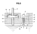
- a modified extra oil pump 22' shown in Fig. 5 may be used. That is, this modified pump 22' is installed in servo piston body 18. Plunger 26 is slidably received in a bore formed in servo piston body 18, which is biased toward eccentric cam 24 by spring 27 installed in the bore. Inlet port 28 and outlet port 30 are also formed in servo piston body 18, which are connected to pump chamber 18a. Although now shown, inlet and outlet valves are installed in inlet and outlet ports 28 and 30 respectively. Thus, under rotation of eccentric cam 24, oil in the oil pan is led into outlet port 30 through inlet port 28 and pump chamber 18a. Servo piston body 18 is further formed with an outlet passage 32' which is connected with outlet port 30.
- modified oil pump 22' has no means that has the forward/reverse sensor function possessed by the above-mentioned pump housing 25 of the extra oil pump 22.
- modified oil pump 22' has to use a mechanical reverse sensor which can sense a reversed rotation of countershaft 15. That is, upon sensing such reversed rotation by the sensor, a suitable member shifts spool 33a (see Fig. 3) of valve 33 to the left position.
- plunger 26 is operatively received in a bore formed in a separate body member that is connected to servo piston body 18, one is a type wherein plunger 26 is operatively installed in a bore formed in a body 46 (see Fig. 3) of forward/reverse switching valve 33, and the other is a type wherein plunger 26 is operatively received in a bore formed in a separate body member that is connected to the body 46.
- FIG. 4 there is shown a hydraulic circuit for controlling operation of transmission 100 of the first embodiment. As is seen from this drawing, outlet pipe 32 from extra oil pump 22 is led to the hydraulic circuit.
- Hydraulic circuit comprises a line pressure producing circuit (viz., LPPC) 36 which produces a line pressure "PL” by adjusting a hydraulic pressure produced by oil pump 21 driven by engine 1.
- Line pressure "P L” is fed to a main circuit 34 and a sub-circuit 35.
- main circuit 34 there is connected a forward speed control valve (viz., FSCV) 37, and to sub-circuit 35, there is connected a sub-circuit 48 through ports 33c and 33d of the above-mentioned forward/reverse switching valve 33.
- a reverse speed control valve 38 To sub-circuit 48, there is connected a reverse speed control valve 38.
- Forward and reverse speed control valves 37 and 38 may be the ones which are disclosed in Laid-open Japanese Patent Application (Tokkaihei) 11-94062.
- forward and reverse speed control valves 37 and 38 and low and high side piston chambers 18L and 18H of the above-mentioned servo piston 13 there is arranged the forward/reverse switching valve 33.
- These valves 37, 38 and 33 are installed in body 46 (see Fig. 3) of the valve 33.
- Forward speed control valve 37 comprises a spool 37a which is connected to a middle portion of a speed control lever 39. A first end of this control lever 39 is moved by a step motor (viz., S.M.) to a position that corresponds to an instructed speed change ratio. A second end of control lever 39 abuts on a forward precess cam (viz., F.P.C) for achieving a feedback control of transmission 100.
- a step motor viz., S.M.
- F.P.C forward precess cam
- control lever 39 is forced to pivot about the second end thereof in the corresponding direction.
- spool 37a is moved in a corresponding direction in the valve body, so that line pressure "P L " of main circuit 34 is fed to one of output circuits 40 and 41 drawing the pressure from the other of the circuits 40 and 41.
- the pressure is fed to low or high side piston chamber 18L or 18H of piston body 18 through one of output circuits 42 and 43, so that due to a pressure difference between two chambers 18L and 18H, servo piston 13 is moved from a neutral position to a desired position for the instructed speed change ratio.
- a spool 38a of the valve 38 is shifted through a reverse precess cam (viz., R.P.C.) in such a direction as to move the actually made speed change ratio toward a fixed reverse speed ratio that is instructed.
- line pressure "P L " is applied from sub-circuit 35 (48) to one of output circuits 44 (42) and 45 (43) while draining oil from the other of the circuits.
- servo piston 13 is moved from the neutral position to a desired position for achieving the instructed reverse speed change ratio.
- the reverse precess cam (R. P. C.) is turned in a manner to return servo piston 13 toward the neutral position, and when the actually made speed change ratio of transmission 100 becomes into coincidence with the instructed reverse speed change ratio, the reverse precess cam is turned to such a position as to place spool 38 to the original position to close both output circuits 44 and 45. With this, the reverse speed change ratio thus instructed is kept by transmission 100.
- forward/reverse switching valve 33 assumes a condition wherein output circuits 42 and 43 are communicated with output circuits 44 and 45 respectively.
- outlet pipe 32 from extra oil pump 22 is connected to sub-circuit 35.
- This sub-circuit 35 corresponds to a so-called line pressure input circuit for reverse speed control valve 38 for forward/reverse switching valve 33 which permits oil feeding to reverse speed control valve 38 only under reverse movement of the vehicle.
- Extra oil pump 22 is equipped with a pressure relief valve 50 by which the internal pressure of outlet pipe 32 is kept below the valve opening pressure of this valve 50.
- Outlet pipe or outlet circuit 32 has a check valve 51 installed therein for suppressing oil backflow toward extra oil pump 22.
- Sub-circuit 35 is connected to a downstream part of outlet circuit 32 through a check valve 52. Due to this check valve 52, oil backflow in sub-circuit 35 toward the engine driven oil pump 21 is suppressed.
- Check valves 51 and 52 are constructed to have a smaller valve opening pressure, while, check valve 54 has a valve opening pressure higher than that of check valves 51 and 52 but smaller than that of relief valve 50.
- Plate spring 55 for biasing servo piston 13 toward high side piston chamber 18H.
- Plate spring 55 is arranged to produce such a basing force as to move servo piston 13 to at least a neutral position.
- this plate spring 55 functions to suppress undesired high speed change ratio starting of the vehicle which would occur when the vehicle has been hauled with its front face facing forward. That is, if plate spring 55 is not present, such hauling tends to induce that servo piston 13 is moved from high side piston chamber 18H toward low side piston chamber 18L bringing about up-shifting movement in transmission 100. However, due to provision of the plate spring 55, such undesired movement of servo piston 13 toward low side piston chamber 18L is suppressed and thus the high speed staring of the vehicle does not occur.
- forward/reverse switching valve 33 takes the forward position as shown in Fig. 4, and thus, the above-mention forward speed change is carried out through forward speed control valve 37 using the line pressure "PL" from main circuit 34 as a base pressure.
- forward/reverse switching valve 3 takes the reverse position (not shown), that is, the depressed position in Fig. 4, and thus, the above-mentioned reverse speed change is carried out through reverse speed control valve 38 using the line pressure "P L " from sub-circuit 35 as a base pressure.
- extra oil pump 22 (or 22') can produce oil pressure in accordance with turning speed of the cam 24 irrespective of the turning direction of the same.
- extra oil pump 22 (or 22') fails to produce a satisfied oil pressure for establishing the fixed reverse speed change ratio in transmission 100, the following operation takes place.
- each trunnion 12 (see Fig. 4) is urged to get ready for movement in the direction of the arrow " ⁇ " from its neutral position forcing transmission 100 to be ready for up-shifting.
- This urged movement of trunnion 12 induces a feed-back movement of spool 38a of reverse speed control valve 38 in the direction of the arrow "p" through the reverse precess cam (R.P.C.).
- reverse speed control valve 38 establishes the communication between output circuit 44 and a port 38b and the communication between sub-circuit 48 and output circuit 45 feeding oil pressure in sub-circuit 48 to output circuit 45.
- oil pressure in low side piston chamber 18L is reduced and at the same time oil pressure in high side piston chamber 18H is increased thereby avoiding the above-mentioned stroke of trunnion in the direction of the arrow " ⁇ ".
- servo piston 13 Due to pressure reduction in low side piston chamber 18L and pressure increase in high side piston chamber 18H, servo piston 13 is moved upward in Fig. 4 against the biasing force of plate spring 55, so that trunnion 12 is shifted in a corresponding direction inducing a down-shifting of transmission 100.
- transmission 100 can keep the reserve speed change ratio at the predetermined lower ratio side.
- non-smoothed start movement of the vehicle viz., high speed change ratio starting of the vehicle
- transmission 100 can keep the reserve speed change ratio at the predetermined lower ratio side.
- check valve 52 Due to provision of check valve 52, undesired escape of oil pressure from outlet circuit 32 toward sub-circuit 35 is suppressed, and thus, the undesired high speed change ratio starting of the vehicle is assuredly avoided.
- forward/reverse switching valve 33 assumes the position as shown in Fig. 4 blocking the communication between ports 33c and 33d. Accordingly, the oil pressure in outlet circuit 32 is not led to reverse speed control valve 38. Forward speed control valve 37 is applied with no oil pressure. Thus, both the low and high side piston chambers 18L and 18H of servo piston 13 are not applied with oil pressure.
- servo piston 13 is forced to take a position that is determined by a biasing force of plate spring 55.
- plate spring 55 is so set as to bias servo piston 13 to move to the above-mentioned neutral position.
- servo piston 13 is prevented from moving toward low side piston chamber 18L from high side piston chamber 18H beyond the neutral position. Accordingly, speed change shifting toward a higher speed change ratio side under coasting of the vehicle or traction of the vehicle with its front face facing forward is avoided, and thus, undesired high speed change ratio starting of the vehicle is suppressed.
- transmission 100 is prevented from making up-shifting movement toward a higher speed change ratio side, and thus, undesired high speed change ratio starting of the vehicle is avoided.
- oil pressure produced by extra oil pump 22 or 22' is applied to only reverse speed control valve 38.
- oil pressure escape at forward speed control valve 37 can be minimized and thus, extra oil pump 22 or 22' can be made compact in size.
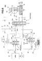
- FIG. 6 there is shown a hydraulic circuit that is employed in a toroidal type continuously variable transmission 200 of the second embodiment of the present invention.
- reverse speed control valve 38 is arranged in main circuit 34 and forward speed control valve 37 is arranged in sub-circuit 37.
- forward/reverse switching valve 33 is arranged to take an opposite operation to the valve 33 employed in the first embodiment. That is, valve 33 shows the illustrated condition when the driven road wheels of the vehicle rotate in a reverse direction, and when the vehicle is under coasting, spool 33a of the valve 33 takes a depressed position (not shown) against the force of spring 33b, that is, the forward position. Accordingly, arrangement of forward and reverse speed control valves 37 and 38 relative to forward/reverse switching valve 33 is opposite to that in case of the above-mentioned first embodiment.
- a mechanical forward sensor should be used for shifting spool 33a of forward/reverse switching valve 33.
- oil in circuit 48 is used for lubricating the forward sensor.
- a plate spring 56 is installed in the high side piston chamber 18H of servo piston 13 for biasing servo piston 13 toward low side piston chamber 18L. That is, for biasing servo piston 13 toward its neutral position, plate spring 56 is used.
- plate spring 56 operates for preventing the high speed change ratio starting of the vehicle. That is, due to function of plate spring 56, undesired movement of servo piston 13 in the direction from low side piston chamber 18L toward high side piston chamber 18H, which would take place when the vehicle is being hauled with its front face facing backward, is prevented.
- forward/reverse switching valve 33 Under backward movement of the vehicle, forward/reverse switching valve 33 the illustrated reverse position, and thus, the above-mentioned backward speed change operation is carried out through reverse speed control valve 38 using line pressure "P L " from main circuit 34 as a base pressure.
- extra oil pump 22 (or 22') is operated to produce oil pressure that is led to output circuit 32.
- forward/reverse switching valve 33 takes the depressed or forward position (not shown) establishing the communication between ports 33c and 33d, and thus, the oil pressure produced by extra oil pump 22 (or 22') is led to forward speed control valve 37 through outlet circuit 32, check valve 51, ports 33c and 33d and sub-circuit 48.
- forward speed control valve 37 a lowest speed change ratio is kept by transmission 200 using the oil pressure produced by extra oil pump 22 (or 22') as a base pressure.
- extra oil pump 22 (or 22') fails to produce a satisfied oil pressure for establishing the lowest speed change ratio in transmission 200, the following operation takes place.
- trunnion 12 is urged to get ready for movement in the direction of the arrow " ⁇ " from its neutral position forcing transmission 200 to be ready for up-shifting.
- This urged movement of trunnion 12 induces a feed-back movement of speed control lever 39 in the direction of the arrow " ⁇ " through the forward precess cam (not shown).
- forward speed control valve 37 establishes the communication between output circuit 44 and sub-circuit 48 and the communication between output circuit 45 and a drain port 37b, so that the oil pressure in low side piston chamber 18L is increased and the oil pressure in high side piston chamber 18H is reduced. As a result, the above-mentioned stroke of trunnion 12 in the direction of the arrow " ⁇ " does not take place.
- servo piston 13 Due to pressure increase in low side piston chamber 18L and pressure reduction in high side piston chamber 18H, servo piston 13 is moved is moved downward in Fig. 6 against the biasing force of plate spring 56, so that trunnion 12 is shifted in a corresponding direction inducing a down-shifting of transmission 200.
- transmission 200 can keep the reverse speed change ratio at the lowest side.
- undesired high speed change ratio starting of the vehicle is suppressed at a subsequent starting of the same.
- check valve 52 Due to provision of check valve 52, undesired escape of oil pressure from outlet circuit 32 toward sub-circuit 35 is suppressed, and thus, the undesired high speed change ratio starting of the vehicle is assuredly avoided.
- forward/reverse switching valve 33 assumes the position as shown in Fig. 6 blocking the communication between ports 33c and 33d. Accordingly, the oil pressure in outlet circuit 32 is not led to forward speed control valve 37. Reverse speed control valve 38 is applied with no oil pressure. Thus, both the low and high side piston chambers 18L and 18H of servo piston 13 are not applied with oil pressure.
- servo piston 13 is forced to take a certain position that is determined by a biasing force of plate spring 56.
- plate spring 56 is so set as to bias servo piston 13 to move to the neutral position.
- servo piston 13 is prevented from moving toward high side piston chamber 18H from low side piston chamber 18L beyond the neutral position. Accordingly, up-shifting toward a higher speed change ratio side under the traction of the vehicle is avoided and thus, undesired high speed change ratio starting of the vehicle is suppressed.
- transmission 200 is prevented from making up-shifting movement toward a higher speed change ratio side, and thus, undesired high speed change ratio starting of the vehicle is avoided.
- oil pressure produced by extra oil pump 22 or 22' is applied to only forward speed control valve 37.
- oil pressure escape at reverse speed control valve 38 can be minimized and thus, extra oil pump 22 or 22' can be made compact in size.
Landscapes
- Engineering & Computer Science (AREA)
- General Engineering & Computer Science (AREA)
- Mechanical Engineering (AREA)
- Control Of Transmission Device (AREA)
- Friction Gearing (AREA)
Abstract
When, with engine kept stopped, driven road wheels are
turned, the toroidal type continuously variable transmission is
suppressed from shifting toward a higher speed side. That is,
when, with the engine kept stopped, the road wheels are turned
in a reverse direction due to a traction of a motor vehicle with its
front end facing backward, an extra oil pump (22) driven by the road
wheels produces an oil pressure which is applied to a hydraulic
servo mechanism (13,18L,18H) to keep a speed change ratio at a lower speed
side. While, when, with the engine kept stopped, the road
wheels are turned in a forward direction due to a traction of the
motor vehicle with its front end facing forward, the oil pressure
produced by the extra oil pump (22) is not practically used. Under
this condition, a biasing spring (55) suppresses a servo piston (13) from
moving in a direction to bring about a speed change ratio for the
higher speed side.
Description
- The present invention relates in general to continuously variable transmissions, and more particularly, to toroidal type continuously variable transmissions for wheeled motor vehicles.
- As is described in Laid-open Japanese Patent Application (Tokkaihei) 10-331938, a toroidal type continuously variable transmission for use with a wheeled motor vehicle comprises generally an input disc which receives a torque from an engine, an output disc which is coaxially arranged with the input disc and constantly engaged with driven road wheels to drive the same, power rollers which are each interposed between the input and output discs to transmit power therebetween by shearing oil film, and trunnions which rotatably support the power rollers. For controlling the transmission, there are employed an oil pump which is constantly driven by the engine, a forward speed control valve which is used under forward movement of the vehicle, a reverse speed control valve which is used under reverse movement of the vehicle, and a hydraulic servo mechanism which moves each trunnion in a manner to pivot the power roller between a neutral position where a rotation axis of the power roller intersects a common axis of the input and output discs and an offset position where the rotation axis of the power roller is offset toward a shaft axis of the corresponding trunnion.
- Upon need of a speed change of the transmission under forward movement of the vehicle, a hydraulic pressure from the oil pump is directed to the hydraulic servo mechanism under control of the forward speed control valve, so that a controlled hydraulic pressure drives servo pistons of the hydraulic servo mechanism for moving the trunnions to pivot each power roller to a desired angled position.
- With this, the power rollers are each applied, from the input and output discs, with a component force around the shaft axis of the corresponding trunnion, and thus, each power roller is forced to make a self-inclination around a shaft axis of the trunnion while continuously changing the radius of a circular arc described by the power roller and each of the input and output discs at their contacting portions. With this, a continuously variable speed change is carried out by the transmission.
- During the operation, the progress of the speed change is fed back to the hydraulic servo mechanism, so that each trunnion is gradually returned toward the original shaft axis position, and when the speed change ratio actually made in the transmission becomes into coincidence with an instructed ratio, each power roller is returned to the neutral position allowing the transmission to keep the instructed speed change ratio.
- Under operation of the engine, the hydraulic pressure is kept produced by the oil pump and thus the hydraulic servo mechanism is controllable.
- However, when, with the engine kept stopped, the vehicle is under a coasting movement or being hauled, a torque is inputted from the driven road wheels to the output disc in a way contrary to the case of normal movement of the vehicle. In this condition of the vehicle, the hydraulic servo mechanism is dead, and thus, for the following reason, it tends to occur that an up-shifting is carried out in the transmission.
- That is, when the output disc is fed with the torque from the driven road wheels, each power roller is compelled to receive a component force in a direction of the trunnion shaft axis from the contact portion with the input disc using a certain friction on the input disc as a so-called reaction force receiver, and thus each power roller becomes offset in the direction of the trunnion shaft axis and due to the above-mentioned self-inclination of the power roller, a speed change ratio for a higher speed side is set in the transmission. Of course, this phenomenon brings about a lack of torque directed to the driven road wheels at a subsequent starting of the vehicle and thus smoothed starting of the vehicle is not obtained.
- Accordingly, it is an object of the present invention to provide a toroidal type continuously variable transmission which is free of the above-mentioned drawback.
- According to the present invention, there is provided a toroidal type continuously variable transmission in which when, with the engine kept stopped, the driven road wheels are rotated due to a traction of the vehicle or the like, an extra oil pump is driven by the driven road wheels for operating the hydraulic servo mechanism in a manner to suppress the above-mentioned undesired up-shifting movement in the transmission.
- According to the present invention, there is provided a toroidal type continuously variable transmission which comprises an input disc adapted to be driven by a prime mover of a motor vehicle; an output disc coaxially arranged with the input disc, the output disc being adapted to be constantly connected to road wheels of the vehicle; power rollers each being interposed between the input and output discs to transmit a torque from the input disc to the output disc through the power rollers; trunnions rotatably supporting the power rollers respectively; a main oil pump powered by the prime mover; a line pressure producing circuit which produces a line pressure by adjusting an oil pressure produced by the main oil pump; a hydraulic servo mechanism powered by the main oil pump, the hydraulic servo mechanism inducing a speed change between the input and output discs by actuating the trunnions in such a manner as to pivot a rotation axis of each power roller between a neutral position where the rotation axis intersects a common axis of the input and output discs at right angles and an offset position where the rotation axis is shifted toward a shaft axis of the trunnion while being offset relative to the common axis; a forward speed control valve through which the line pressure passes when the vehicle moves forward; a reverse speed control valve through which the line pressure passes when the vehicle moves backward; a feedback mechanism which feeds back a progress of the speed change to the hydraulic servo mechanism so that when a practical speed change ratio between the input and output discs becomes in coincidence with an instructed ratio, each power roller is returned to the neutral position; a forward/reverse switching valve which selectively feeds the line pressure to one of the forward and reverse speed control valves in accordance with a direction in which the vehicle moves, the forward/reverse switching valve having a line pressure inlet part to which the line pressure is applied; an extra oil pump powered by the road wheels; and an extra hydraulic circuit which feeds an oil pressure produced by the extra oil pump to the line pressure inlet part of the forward/reverse switching valve.
-
- Fig. 1 is a schematically illustrated power path for a wheeled motor vehicle, which includes a toroidal type continuously variable transmission of a first embodiment of the present invention;
- Fig. 2 is an enlarged sectional view of a part of the transmission of the first embodiment, showing an extra oil pump;
- Fig. 3 is an enlarged sectional view of the extra oil pump incorporated with a forward/reverse switching valve;
- Fig. 4 is a hydraulic circuit for controlling operation of the transmission of the first embodiment;
- Fig. 5 is a sectional view of another extra pump incorporated with a servo piston body; and
- Fig. 6 is a view similar to Fig. 4, but showing a hydraulic circuit employed in a second embodiment of the present invention.
-
- In the following, embodiments of the present invention will be described in detail with the aid of the accompanying drawings.
- Referring to Figs. 1 to 4, there is shown a toroidal type continuously variable transmission of a first embodiment of the present invention, which is generally designated by
numeral 100. - In Fig. 1, there is shown a power path for a wheeled motor vehicle, which is incorporated with the
transmission 100 of the first embodiment. - The power path includes an
engine 1, atorque converter 2, a forward/reverse switching mechanism (viz., F/RSM) 3 andtransmission 100. That is, output power (viz., torque) ofengine 1 is transmitted throughtorque converter 2 to forward/reverse switching mechanism 3. This switching mechanism 3 has generally three functions, the first being to transmit the rotation of a turbine ofconverter 2 totransmission 100 directly as in case of D-range state, the second being to transmit the rotation of the turbine totransmission 100 while changing rotation direction as in case of R-range state and the third being to block the connection between the turbine andtransmission 100 as in case of P-range or N-range state. - The toroidal type continuously
variable transmission 100 is of a double cavity type which comprises front and rear toroidal power transmittingunits - Toroidal
power transmitting units input disc 6, anoutput disc 7 arranged to faceinput disc 6, and a pair ofpower rollers 8 each being sandwiched between input andoutput discs - As shown, the two
units output discs 7 set in a back to back manner. Theinput disc 6 of thefront unit 4 is connected to a driven member of switching mechanism 3 to rotate therewith. -
Transmission 100 further comprises amain shaft 9 which has both ends to whichinput discs 6 of the twounits input discs 6 of the twounits - As shown,
output discs 7 of the twounits main shaft 9. - These two
output discs 7 are integrally connected to each other through ahollow output shaft 10.Hollow output shaft 10 has anoutput gear 11 tightly disposed thereon. - As is seen from Fig. 4, each
power roller 8 is rotatably supported by atrunnion 12. A rotation axis of thepower roller 8 is denoted by reference "O1", which will be referred to "power roller rotation axis" hereinafter. Designated by reference "O2" is a shaft axis of thetrunnion 12, which will be referred to "trunnion shaft axis" hereinafter. This axis "O2" intersects with power roller rotation axis "O1" at right angles. Designated by reference "O3" is a rotation axis of input andoutput discs - Each
trunnion 12 has a lower end equipped with aservo piston 13 which is a part of a hydraulic servo mechanism. Servopiston 13 is slidably received in aservo piston body 18 to define therein low and highside piston chambers power rollers 8, lowside piston chamber 18L is positioned nearer to the associatedpower roller 8 than highside piston chamber 18H is. - Referring back to Fig. 1, for supporting the four
power rollers 8, fourtrunnions 12 are respectively used, which are synchronously stroked in the same phase for carrying out a speed change operation oftransmission 100. - In the following, the speed change operation of
transmission 100 will be briefly described. - Rotation from forward/reverse switching mechanism 3 is transmitted to both
input discs 6 of front andrear units input disc 6 is transmitted to the corresponding twopower rollers 8 causing the same to rotate about their rotation axes "O1" respectively. - Rotation of the two
power rollers 8 of eachunit corresponding output disc 7, and the rotation of twooutput discs 7 of the twounits output gear 11, acounter gear 14 meshed withoutput gear 11, acountershaft 15 and agear unit 16 to anoutput shaft 17 which is coaxially arranged withmain shaft 9. Although not shown in the drawing,output shaft 17 is connected to driven road wheels through a differential gear. - When, now, due to synchronous operation of
servo pistons 13 and thus synchronous operation oftrunnions 12, each rotatingpower roller 8 is shifted or inclined from a neutral position (viz., non-speed change position) shown in Figs. 1 and 4 toward the trunnion shaft axis "O2" offsetting power roller rotation axis "O1" relative to input/output disc rotation axis "O3", eachpower roller 8 is inclined around trunnion shaft axis "O2" due to a component force produced. - Due to such self-inclination of each
power roller 8, the radius of a circular arc described by thepower roller 8 and each of input andoutput discs units - When the speed change ratio actually made in
transmission 100 becomes into coincidence with an instructed ratio, allpower rollers 8 are retuned to their initial neutral positions due to the work ofservo pistons 13 andtrunnions 12. Under this state, the instructed speed change ratio can be kept intransmission 100. - When, under the above-mentioned speed change operation with
transmission 100 kept in D-range, highside piston chamber 18H of the hydraulic servo mechanism (see Fig. 4) is fed with a hydraulic pressure and at the same time a hydraulic pressure in lowside piston chamber 18L is discharged,servo piston 13 is shifted upward in the drawing causing up-shifting movement toward a higher speed change ratio intransmission 100. While, when the hydraulic pressure in highside piston chamber 18H is discharged and at the same time lowside piston chamber 18H is fed with a hydraulic pressure,servo piston 13 is shifted downward causing down-shifting movement toward a lower speed change ratio intransmission 100. - While, when, under the above-mentioned speed change operation with
transmission 100 kept in R-range, highside piston chamber 18H is fed with a hydraulic pressure and at the same time the hydraulic pressure in lowside piston chamber 18L is discharged,servo piston 13 is shifted upward. But, due to the reverse function of the forward/reverse switching mechanism 3, the upward sifting ofservo piston 13 induces down-shifting movement toward the lower speed change ratio intransmission 100. While, when the hydraulic pressure in highside piston chamber 18H is discharged and at the same time lowside piston chamber 18L is fed with a hydraulic pressure, up-shifting movement toward the higher speed change ratio is carried out intransmission 100. - Referring back to Fig. 1, an
oil pump 21 is provided which is driven byengine 1 for producing an oil pressure to control the hydraulic servo mechanism as well as forward/reverse switching mechanism 3. - It is now to be noted that in accordance with the present invention, there is further provided an
extra oil pump 22 which is driven bycountershaft 15. In the illustration,extra oil pump 22 is connected to a front end ofcountershaft 15. -
Countershaft 15 is constantly connected to the driven road wheels (not shown) throughgear unit 16,output shaft 17 and the differential gear (not shown). - Accordingly, when, with
engine 1 kept stopped, the associated motor vehicle is under coasting or being hauled with the driven road wheels put on a road surface,extra oil pump 22 is inevitably driven due to rotation of the driven road wheels. - As is seen from Figs. 2 and 3,
extra oil pump 22 is a plunger pump, which comprises aneccentric cam 24 which is connected to the front end ofcountershaft 15 by means of apin 23, and apump housing 25 which houses thereineccentric cam 24. As is understood from Fig. 3, pumphousing 25 is rotatable about an axis ofcountershaft 15, that is, about a rotation axis ofeccentric cam 24. - A
plunger 26 is slidably received inpump housing 25, which is biased towardeccentric cam 24 by aspring 27, so that an upper end thereof constantly contacts with a cam surface ofcam 24. - As is well shown in Fig. 2, pump
housing 25 has apump chamber 25a incorporated withplunger 26.Pump housing 25 has further inlet andoutlet ports pump chamber 25a. Inlet andoutlet ports outlet valves Intake port 28 is positioned below a level of oil received an oil pan (not shown) oftransmission 100. - Accordingly, when, due to rotation of
countershaft 15,eccentric cam 24 is rotated,plunger 26 is forced to make a reciprocation movement expanding andcontracting pump chamber 25a repeatedly. With this, due to operation of inlet andoutlet valves chamber 25a frominlet port 28 and discharged fromoutlet port 30. - As is seen from Fig. 3, near the lower portion of
pump housing 25, there is stationarily arranged anoutlet pipe 32 which has aleading end 32b insertable intooutlet port 30 ofpump housing 25.Outlet pipe 32 has acircular flange 32a fixed thereto. - When, as is seen from the drawing,
eccentric cam 24 is rotated in the direction of the arrow "α" in response to forward movement of the vehicle, pumphousing 25 is forced to pivot in the same direction ascam 24 due to a dragging work ofcam 24 applied toplunger 26 and thus, pumphousing 25 is stopped at an illustrated position "A" wherecircular flange 32a ofoutlet pipe 32 abuts on the lower portion ofpump housing 25 having theleading end 32b received inoutlet port 30. - While, when
eccentric cam 24 is rotated in the opposite direction, that is, in the direction of the arrow "β" in response to reverse movement of the vehicle, pumphousing 25 is forced to swing in the opposite direction and stopped at a position "B" indicated by a phantom line keeping the fluid connection between theleading end 32b ofoutlet pipe 32 andoutlet port 30. - As will be described in detail hereinafter, the swing movement of
pump housing 25 from position "A" to position "B" shifts a forward/reverse switching valve (viz., F/RSV) 33 to a reverse position. That is, due to the swing movement ofpump housing 25, aspool 33a ofvalve 33 is pushed into the bore againstspring 33b to a depressed position, viz., the reverse position. - More specifically, when
pump housing 25 is in the illustrated position "A",spool 33a assumes the illustrated right position, and when pumphousing 25 is swung from the illustrated position "A" to the inclined position "B",spool 33a is moved leftward to assume a left position (not shown). Thus, when, withengine 1 kept stopped, the vehicle is being hauled with its front face facing backward, pumphousing 25 assumes the inclined position "B" and thusspool 33a assumes its left position (not shown). - Accordingly, pump
housing 25 ofextra oil pump 22 has a so-called forward/reverse sensor function. - If desired, in place of the
extra oil pump 22 having the above-mentioned construction, a modified extra oil pump 22' shown in Fig. 5 may be used. That is, this modified pump 22' is installed inservo piston body 18.Plunger 26 is slidably received in a bore formed inservo piston body 18, which is biased towardeccentric cam 24 byspring 27 installed in the bore.Inlet port 28 andoutlet port 30 are also formed inservo piston body 18, which are connected to pumpchamber 18a. Although now shown, inlet and outlet valves are installed in inlet andoutlet ports eccentric cam 24, oil in the oil pan is led intooutlet port 30 throughinlet port 28 and pumpchamber 18a.Servo piston body 18 is further formed with an outlet passage 32' which is connected withoutlet port 30. - The modified oil pump 22' has no means that has the forward/reverse sensor function possessed by the above-mentioned
pump housing 25 of theextra oil pump 22. Thus, when practically used, modified oil pump 22' has to use a mechanical reverse sensor which can sense a reversed rotation ofcountershaft 15. That is, upon sensing such reversed rotation by the sensor, a suitable member shiftsspool 33a (see Fig. 3) ofvalve 33 to the left position. - Furthermore, other types of oil pump may be used in the invention as the
extra oil pump 22. One is a type whereinplunger 26 is operatively received in a bore formed in a separate body member that is connected toservo piston body 18, one is a type whereinplunger 26 is operatively installed in a bore formed in a body 46 (see Fig. 3) of forward/reverse switching valve 33, and the other is a type whereinplunger 26 is operatively received in a bore formed in a separate body member that is connected to thebody 46. - Referring to Fig. 4, there is shown a hydraulic circuit for controlling operation of
transmission 100 of the first embodiment. As is seen from this drawing,outlet pipe 32 fromextra oil pump 22 is led to the hydraulic circuit. - Hydraulic circuit comprises a line pressure producing circuit (viz., LPPC) 36 which produces a line pressure "PL" by adjusting a hydraulic pressure produced by
oil pump 21 driven byengine 1. Line pressure "PL" is fed to amain circuit 34 and a sub-circuit 35. - To
main circuit 34, there is connected a forward speed control valve (viz., FSCV) 37, and to sub-circuit 35, there is connected a sub-circuit 48 throughports reverse switching valve 33. To sub-circuit 48, there is connected a reversespeed control valve 38. - Forward and reverse
speed control valves - Between forward and reverse
speed control valves side piston chambers servo piston 13, there is arranged the forward/reverse switching valve 33. Thesevalves valve 33. - Forward
speed control valve 37 comprises aspool 37a which is connected to a middle portion of aspeed control lever 39. A first end of thiscontrol lever 39 is moved by a step motor (viz., S.M.) to a position that corresponds to an instructed speed change ratio. A second end ofcontrol lever 39 abuts on a forward precess cam (viz., F.P.C) for achieving a feedback control oftransmission 100. - That is, when, due to operation of the step motor, the first end of
control lever 39 is shifted to the position that corresponds to the instructed speed change ratio,control lever 39 is forced to pivot about the second end thereof in the corresponding direction. With this,spool 37a is moved in a corresponding direction in the valve body, so that line pressure "PL" ofmain circuit 34 is fed to one ofoutput circuits circuits side piston chamber piston body 18 through one ofoutput circuits chambers servo piston 13 is moved from a neutral position to a desired position for the instructed speed change ratio. - Progress of this speed change movement is fed back to the second end of
speed control lever 39 through the forward precess cam, so thatservo piston 13 is moved toward the neutral position with progress of the speed change movement. That is, when a speed change ratio actually made intransmission 100 becomes into coincidence with the instructed speed change ratio,speed control lever 39moves spool 37a to the original position where bothoutput circuits transmission 100. - When
spool 33a of forward/reverse switching valve 33 is shifted from the position shown in Fig. 4 to an upper position due to reverse movement of the vehicle,ports output circuits circuits blocking output circuits speed control valve 38 carries out the following speed change operation. - That is, upon the above-mentioned operation, a
spool 38a of thevalve 38 is shifted through a reverse precess cam (viz., R.P.C.) in such a direction as to move the actually made speed change ratio toward a fixed reverse speed ratio that is instructed. With this, line pressure "PL" is applied from sub-circuit 35 (48) to one of output circuits 44 (42) and 45 (43) while draining oil from the other of the circuits. With this, due to a pressure difference between low and highside piston chambers servo piston 13 is moved from the neutral position to a desired position for achieving the instructed reverse speed change ratio. - During the speed change operation, the reverse precess cam (R. P. C.) is turned in a manner to return
servo piston 13 toward the neutral position, and when the actually made speed change ratio oftransmission 100 becomes into coincidence with the instructed reverse speed change ratio, the reverse precess cam is turned to such a position as to placespool 38 to the original position to close bothoutput circuits transmission 100. - As is shown in the drawing (Fig. 4), normally, due to the biasing force of
spring 33b,spool 33a of forward/reverse switching valve 33 is biased to take the forward position as shown whereoutput circuits output circuits speed control valve 37 is carried out. - In this forward position, the connection between
ports speed control valve 38 fromsub-circuit 35, and thus, the above-mentioned speed change control by reversespeed control valve 38 is not carried out. - As has been mentioned in the description of Figs. 2 and 3, during reverse movement of the vehicle, due to the pivot movement of
pump housing 25 ofextra oil pump 22 or the work of the reverse sensor by whichspool 33a is pushed into the reverse position againstspring 33b, forward/reverse switching valve 33 assumes a condition whereinoutput circuits output circuits - In this reverse position, the connection between
ports speed control valve 38 fromsub-circuit 35 throughsub-circuit 48. Accordingly, the above-mentioned speed change control by reversespeed control valve 38 is carried out. - In case of usage of the reverse sensor for shifting
spool 33a to the reverse position, lubrication of the reverse sensor is necessary. This lubrication is achieved by oil that is fed from sub-circuit 48 through acheck valve 49. In this case, the valve opening pressure of thischeck valve 49 is so set that line pressure "PL" insub-circuit 48 is not lowered to such a degree as to influence the speed change control by reversespeed control valve 38. - As is shown in Fig. 4,
outlet pipe 32 fromextra oil pump 22 is connected to sub-circuit 35. - This sub-circuit 35 corresponds to a so-called line pressure input circuit for reverse
speed control valve 38 for forward/reverse switching valve 33 which permits oil feeding to reversespeed control valve 38 only under reverse movement of the vehicle.Extra oil pump 22 is equipped with apressure relief valve 50 by which the internal pressure ofoutlet pipe 32 is kept below the valve opening pressure of thisvalve 50. - Outlet pipe or
outlet circuit 32 has acheck valve 51 installed therein for suppressing oil backflow towardextra oil pump 22. Sub-circuit 35 is connected to a downstream part ofoutlet circuit 32 through acheck valve 52. Due to thischeck valve 52, oil backflow insub-circuit 35 toward the engine drivenoil pump 21 is suppressed. - From
outlet circuit 32 upstream ofcheck valve 51, there extends a powerroller lubrication circuit 53 which is led to a lubrication portion of eachpower roller 8. Thiscircuit 53 has acheck valve 54 for suppressing oil backflow. - Check
valves check valve 54 has a valve opening pressure higher than that ofcheck valves relief valve 50. - Within low
side piston chamber 18L ofservo piston body 18, there is installed aplate spring 55 for biasingservo piston 13 toward highside piston chamber 18H.Plate spring 55 is arranged to produce such a basing force as to moveservo piston 13 to at least a neutral position. - As will be described hereinafter, this
plate spring 55 functions to suppress undesired high speed change ratio starting of the vehicle which would occur when the vehicle has been hauled with its front face facing forward. That is, ifplate spring 55 is not present, such hauling tends to induce thatservo piston 13 is moved from highside piston chamber 18H toward lowside piston chamber 18L bringing about up-shifting movement intransmission 100. However, due to provision of theplate spring 55, such undesired movement ofservo piston 13 toward lowside piston chamber 18L is suppressed and thus the high speed staring of the vehicle does not occur. - In the following, operation of
transmission 100 for speed change will be described with the aid of the drawings. - Under cruising, that is, when the vehicle runs forward, countershaft 15 (see Fig. 3) turns
eccentric cam 24 ofextra oil pump 22 in the direction of the arrow "α" (or the reverse sensor senses the forward rotation ofcountershaft 15 in case of the modified extra oil pump 22' of Fig. 5). Thus, forward/reverse switching valve 33 takes the forward position as shown in Fig. 4, and thus, the above-mention forward speed change is carried out through forwardspeed control valve 37 using the line pressure "PL" frommain circuit 34 as a base pressure. - While, under backward movement of the vehicle, countershaft 15 (see Fig. 3) turns
eccentric cam 24 ofextra oil pump 22 in the direction of the arrow "β" (or the reverse sensor senses the reverse rotation ofcountershaft 15 in case of the modified extra oil pump 22' of Fig. 5). Thus, forward/reverse switching valve 3 takes the reverse position (not shown), that is, the depressed position in Fig. 4, and thus, the above-mentioned reverse speed change is carried out through reversespeed control valve 38 using the line pressure "PL" from sub-circuit 35 as a base pressure. - During the reverse speed change, oil flow from sub-circuit 35 toward extra oil pump 22 (or 22') is suppressed by
check valve 51. Thus, interference with speed change operation, which would occur when line pressure "PL" is leaked, is prevented. - When
engine 1 is at a standstill, themain oil pump 21 is kept stopped and thus produces no oil pressure. Accordingly, the above-mentioned speed change operation is not carried out. - While, when, with
engine 1 kept stopped, the driven road wheels are forced to rotate due to coasting or traction of the vehicle, countershaft 15 (see Fig. 3) is forced to turneccentric cam 24 ofextra oil pump 22 in the forward direction of the arrow "α" or in the reverse direction of the arrow "β". - As is described hereinabove, when
eccentric cam 24 is turned, extra oil pump 22 (or 22') can produce oil pressure in accordance with turning speed of thecam 24 irrespective of the turning direction of the same. - More specifically, when, with
engine 1 kept stopped, the driven road wheels are forced to rotate in a reversed direction due to traction of the vehicle with its front face facing backward,countershaft 11 rotateseccentric cam 24 in the direction of the arrow "β" of Fig. 3. Thus, because of drag function ofcam 24 to pumphousing 25, the latter is swung to the position "B" pushing or shiftingspool 33a of forward/reverse switching valve 33 to the depressed position, viz., the reverse position. - With this, as has been mentioned hereinabove,
ports speed control valve 38 throughoutlet circuit 32,check valve 51,ports sub-circuit 48. Thus, due to operation of reversespeed control valve 38, a fixed reverse speed change ratio is kept bytransmission 100 using the oil pressure produced by extra oil pump 22 (or 22') as a base pressure. - If, due to a slower backward movement of the hauled vehicle, extra oil pump 22 (or 22') fails to produce a satisfied oil pressure for establishing the fixed reverse speed change ratio in
transmission 100, the following operation takes place. - That is, under such condition, due to a driving force produced by such backward movement of the hauled vehicle, each trunnion 12 (see Fig. 4) is urged to get ready for movement in the direction of the arrow "ε" from its neutral
position forcing transmission 100 to be ready for up-shifting. This urged movement oftrunnion 12 induces a feed-back movement ofspool 38a of reversespeed control valve 38 in the direction of the arrow "p" through the reverse precess cam (R.P.C.). - With such feed-back movement, reverse
speed control valve 38 establishes the communication betweenoutput circuit 44 and aport 38b and the communication betweensub-circuit 48 andoutput circuit 45 feeding oil pressure insub-circuit 48 tooutput circuit 45. As a result, oil pressure in lowside piston chamber 18L is reduced and at the same time oil pressure in highside piston chamber 18H is increased thereby avoiding the above-mentioned stroke of trunnion in the direction of the arrow "ε". - Due to pressure reduction in low
side piston chamber 18L and pressure increase in highside piston chamber 18H,servo piston 13 is moved upward in Fig. 4 against the biasing force ofplate spring 55, so thattrunnion 12 is shifted in a corresponding direction inducing a down-shifting oftransmission 100. - As has been described hereinabove, even when, with
engine 1 kept stopped, the driven road wheels of the motor vehicle are rotated in a reverse direction due to traction of the vehicle with its front face facing backward,transmission 100 can keep the reserve speed change ratio at the predetermined lower ratio side. Thus, non-smoothed start movement of the vehicle (viz., high speed change ratio starting of the vehicle) at a subsequent starting of the same is prevented. - Due to provision of
check valve 52, undesired escape of oil pressure fromoutlet circuit 32 towardsub-circuit 35 is suppressed, and thus, the undesired high speed change ratio starting of the vehicle is assuredly avoided. - While, when, with
engine 1 kept stopped, the driven road wheels are forced to rotate in a forward direction due to coasting of the vehicle, or traction of the vehicle with its front face facing forward, forward/reverse switching valve 33 assumes the position as shown in Fig. 4 blocking the communication betweenports outlet circuit 32 is not led to reversespeed control valve 38. Forwardspeed control valve 37 is applied with no oil pressure. Thus, both the low and highside piston chambers servo piston 13 are not applied with oil pressure. - Accordingly,
servo piston 13 is forced to take a position that is determined by a biasing force ofplate spring 55. As is described hereinabove,plate spring 55 is so set as to biasservo piston 13 to move to the above-mentioned neutral position. Thus, due to the function of theplate spring 55,servo piston 13 is prevented from moving toward lowside piston chamber 18L from highside piston chamber 18H beyond the neutral position. Accordingly, speed change shifting toward a higher speed change ratio side under coasting of the vehicle or traction of the vehicle with its front face facing forward is avoided, and thus, undesired high speed change ratio starting of the vehicle is suppressed. - As is described hereinabove, when, with
engine 1 kept stopped, the driven road wheels are forced to rotate forward or rearward due to coasting or traction of the vehicle,transmission 100 is prevented from making up-shifting movement toward a higher speed change ratio side, and thus, undesired high speed change ratio starting of the vehicle is avoided. - In the first embodiment of the invention, oil pressure produced by
extra oil pump 22 or 22' is applied to only reversespeed control valve 38. Thus, oil pressure escape at forwardspeed control valve 37 can be minimized and thus,extra oil pump 22 or 22' can be made compact in size. - Referring to Fig. 6, there is shown a hydraulic circuit that is employed in a toroidal type continuously
variable transmission 200 of the second embodiment of the present invention. - As shown, in this second embodiment, unlike the above-mentioned first embodiment, reverse
speed control valve 38 is arranged inmain circuit 34 and forwardspeed control valve 37 is arranged insub-circuit 37. - Furthermore, forward/
reverse switching valve 33 is arranged to take an opposite operation to thevalve 33 employed in the first embodiment. That is,valve 33 shows the illustrated condition when the driven road wheels of the vehicle rotate in a reverse direction, and when the vehicle is under coasting,spool 33a of thevalve 33 takes a depressed position (not shown) against the force ofspring 33b, that is, the forward position. Accordingly, arrangement of forward and reversespeed control valves reverse switching valve 33 is opposite to that in case of the above-mentioned first embodiment. - In case wherein the modified extra oil pump 22' shown in Fig. 5 is used, a mechanical forward sensor should be used for shifting
spool 33a of forward/reverse switching valve 33. For lubricating the forward sensor, oil incircuit 48 is used. - Furthermore, in the second embodiment, a
plate spring 56 is installed in the highside piston chamber 18H ofservo piston 13 for biasingservo piston 13 toward lowside piston chamber 18L. That is, for biasingservo piston 13 toward its neutral position,plate spring 56 is used. - For the reason which will be described in the following,
plate spring 56 operates for preventing the high speed change ratio starting of the vehicle. That is, due to function ofplate spring 56, undesired movement ofservo piston 13 in the direction from lowside piston chamber 18L toward highside piston chamber 18H, which would take place when the vehicle is being hauled with its front face facing backward, is prevented. - In the following, operation of
transmission 200 for speed change will be described with the aid of the drawings. - Under backward movement of the vehicle, forward/
reverse switching valve 33 the illustrated reverse position, and thus, the above-mentioned backward speed change operation is carried out through reversespeed control valve 38 using line pressure "PL" frommain circuit 34 as a base pressure. - While, under cruising, that is, when the vehicle runs forward,
spool 33a of forward/reverse switching valve 33 is shifted to the depressed or forward position (not shown), so that the above-mentioned forward speed change control is carried out through forwardspeed control valve 37 using the line pressure "PL" fromsub-circuits - During the forward speed change, oil flow from sub-circuit 35 toward extra oil pump 22 (or 22') is suppressed by
check valve 51. Thus, interference with speed change operation, which would occur when line pressure "PL" is leaked, is suppressed. - When
engine 1 is at a standstill, themain oil pump 21 is kept stopped and produces no oil pressure. Accordingly, the above-mentioned speed change operation is not carried out. - While, when, with
engine 1 kept stopped, the driven road wheels are forced to rotate due to coasting or traction of the vehicle, extra oil pump 22 (or 22') is operated to produce oil pressure that is led tooutput circuit 32. - When, with
engine 1 kept stopped, the driven road wheels are forced to rotate in a forward direction due to coasting of the vehicle, forward/reverse switching valve 33 takes the depressed or forward position (not shown) establishing the communication betweenports speed control valve 37 throughoutlet circuit 32,check valve 51,ports sub-circuit 48. Thus, due to operation of forwardspeed control valve 37, a lowest speed change ratio is kept bytransmission 200 using the oil pressure produced by extra oil pump 22 (or 22') as a base pressure. - If, due to a slower forward movement of the hauled vehicle, extra oil pump 22 (or 22') fails to produce a satisfied oil pressure for establishing the lowest speed change ratio in
transmission 200, the following operation takes place. - That is, under such condition, due to a driving force produced by such forward movement of the hauled vehicle,
trunnion 12 is urged to get ready for movement in the direction of the arrow "δ" from its neutralposition forcing transmission 200 to be ready for up-shifting. This urged movement oftrunnion 12 induces a feed-back movement ofspeed control lever 39 in the direction of the arrow "γ" through the forward precess cam (not shown). - With such feed-back movement, forward
speed control valve 37 establishes the communication betweenoutput circuit 44 andsub-circuit 48 and the communication betweenoutput circuit 45 and adrain port 37b, so that the oil pressure in lowside piston chamber 18L is increased and the oil pressure in highside piston chamber 18H is reduced. As a result, the above-mentioned stroke oftrunnion 12 in the direction of the arrow "δ" does not take place. - Due to pressure increase in low
side piston chamber 18L and pressure reduction in highside piston chamber 18H,servo piston 13 is moved is moved downward in Fig. 6 against the biasing force ofplate spring 56, so thattrunnion 12 is shifted in a corresponding direction inducing a down-shifting oftransmission 200. - As has been described hereinabove, even when, with
engine 1 kept stopped, the driven road wheels of the motor vehicle are rotated in a forward direction due to causing of the vehicle or traction of the vehicle with its front face facing forward,transmission 200 can keep the reverse speed change ratio at the lowest side. Thus, undesired high speed change ratio starting of the vehicle is suppressed at a subsequent starting of the same. - Due to provision of
check valve 52, undesired escape of oil pressure fromoutlet circuit 32 towardsub-circuit 35 is suppressed, and thus, the undesired high speed change ratio starting of the vehicle is assuredly avoided. - While, when, with
engine 1 kept stopped, the driven road wheels are forced to rotate in a reverse direction due to traction of the vehicle with its front face facing backward, forward/reverse switching valve 33 assumes the position as shown in Fig. 6 blocking the communication betweenports outlet circuit 32 is not led to forwardspeed control valve 37. Reversespeed control valve 38 is applied with no oil pressure. Thus, both the low and highside piston chambers servo piston 13 are not applied with oil pressure. - Accordingly,
servo piston 13 is forced to take a certain position that is determined by a biasing force ofplate spring 56. As is described hereinabove,plate spring 56 is so set as to biasservo piston 13 to move to the neutral position. Thus, due to the function of theplate spring 56,servo piston 13 is prevented from moving toward highside piston chamber 18H from lowside piston chamber 18L beyond the neutral position. Accordingly, up-shifting toward a higher speed change ratio side under the traction of the vehicle is avoided and thus, undesired high speed change ratio starting of the vehicle is suppressed. - As is described hereinabove, when, with
engine 1 kept stopped, the driven road wheels are forced to rotate forward or rearward due to coasting or traction of the vehicle,transmission 200 is prevented from making up-shifting movement toward a higher speed change ratio side, and thus, undesired high speed change ratio starting of the vehicle is avoided. - In the second embodiment of the invention, oil pressure produced by
extra oil pump 22 or 22' is applied to only forwardspeed control valve 37. Thus, oil pressure escape at reversespeed control valve 38 can be minimized and thus,extra oil pump 22 or 22' can be made compact in size. - The entire contents of Japanese Patent Application 2002-209518 (filed July 18, 2002) are incorporated herein by reference.
- Although the invention has been described above with reference to the embodiments of the invention, the invention is not limited to such embodiments as described above. Various modifications and variations of such embodiments may be carried out by those skilled in the art, in light of the above description.
Claims (13)
- A toroidal type continuously variable transmission comprising:an input disc (6) adapted to be driven by a prime mover (1) of a motor vehicle;an output disc (7) coaxially arranged with the input disc (6), the output disc being adapted to be constantly connected to road wheels of the vehicle;power rollers (8) each being interposed between the input and output discs (6, 7) to transmit a torque from the input disc (6) to the output disc (7) through the power rollers (8);trunnions (12) rotatably supporting the power rollers respectively;a main oil pump (21) powered by the prime mover (1);a line pressure producing circuit (36) which produces a line pressure by adjusting an oil pressure produced by the main oil pump (21);a hydraulic servo mechanism (13, 18L, 18H) powered by the main oil pump (21), the hydraulic servo mechanism inducing a speed change between the input and output discs (6, 7) by actuating the trunnions (12) in such a manner as to pivot a rotation axis (O1) of each power roller (8) between a neutral position where the rotation axis (O1) intersects a common axis (O3) of the input and output discs at right angles and an offset position where the rotation axis (O1) is shifted toward a shaft axis (O2) of the trunnion while being offset relative to the common axis (O3);a forward speed control valve (37) through which the line pressure passes when the vehicle moves forward;a reverse speed control valve (38) through which the line pressure passes when the vehicle moves backward;a feedback mechanism (F.P.C., R.P.C.) which feeds back a progress of the speed change to the hydraulic servo mechanism (13, 18L, 18H) so that when a practical speed change ratio between the input and output discs (6, 7) becomes in coincidence with an instructed ratio, each power roller (8) is returned to the neutral position;a forward/reverse switching valve (33) which selectively feeds the line pressure to one of the forward and reverse speed control valves (37, 38) in accordance with a direction in which the vehicle moves, the forward/reverse switching valve (33) having a line pressure inlet part to which the line pressure is applied;an extra oil pump (22) powered by the road wheels; andan extra hydraulic circuit (32) which feeds an oil pressure produced by the extra oil pump (22) to the line pressure inlet part of the forward/reverse switching valve (33).
- A toroidal type continuously variable transmission as claimed in Claim 1, in which a sub-circuit (35) extending between the line pressure producing circuit (36) and the line pressure inlet part of the forward/reverse switching valve (33) is equipped with a check valve (52) for suppressing an oil flow in a direction from the forward/reverse switching valve (33) toward the line pressure producing circuit (36).
- A toroidal type continuously variable transmission as claimed in Claim 1, in which the extra hydraulic circuit is equipped with a check valve (51) for suppressing an oil flow in a direction from the forward/reverse switching valve (33) toward the extra oil pump (22).
- A toroidal type continuously variable transmission as claimed in Claim 1, further comprising a biasing member (55) which obstructs a movement of the trunnion (12) that would be induced by one of the forward and reverse speed control valves (37, 38) for making up-shifting of the transmission when the other of the forward and reverse speed control valves (37, 38) is practically applied with the oil pressure from the extra oil pump.
- A toroidal type continuously variable transmission as claimed in Claim 1, in which the extra oil pump (22) is installed in a body (18) of a servo piston (13) of the hydraulic servo mechanism (13, 18L, 18H) using the servo piston body (18) as a part thereof.
- A toroidal type continuously variable transmission as claimed in Claim 1, in which the extra oil pump (22) is connected to a body of a servo piston of the hydraulic servo mechanism.
- A toroidal type continuously variable transmission as claimed in Claim 1, in which the extra oil pump (22) is installed in a control valve body that has the forward and reverse speed control valves mounted therein.
- A toroidal type continuously variable transmission as claimed in Claim 1, in which the extra oil pump (22) is connected to a control valve body that has the forward and reverse speed control valves mounted therein.
- A toroidal type continuously variable transmission as claimed in Claim 1, in which the output disc (7) and the road wheels are constantly connected through a countershaft (15) that extends in parallel with the common axis (O3) of the input and output discs, and in which the extra oil pump (22) is directly powered by the countershaft (15).
- A toroidal type continuously variable transmission as claimed in Claim 1, in which the extra oil pump comprises:a cam (24) driven by a countershaft (15) through which the output disc (7) is connected to the road wheels;a pump housing (25);a plunger (26) slidably received in the pump housing (25) to define therein a pump chamber (25a), the plunger having one end contactable with the cam (24);a spring (27) installed in the work chamber (25a) to bias the plunger (26) toward the cam (24);inlet and outlet ports (28, 30) connected to the pump chamber (25a) respectively; andinlet and outlet valves (29, 31) installed in the inlet and outlet ports (28, 30) respectively.
- A toroidal type continuously variable transmission as claimed in Claim 10, in which the pump housing (25) is rotatably held by the countershaft (15), and in which the pump housing (25) has a portion to which a spool (33a) of the forward/reverse switching valve (33) is pivotally connected.
- A toroidal type continuously variable transmission as claimed in Claim 1, in which the forward/reverse switching valve (33) feeds the line pressure to the reverse speed control valve (38) only when the road wheels turn in a reversed direction, and in which the hydraulic servo mechanism (13, 18L, 18H) comprises:a servo piston (13) which actuates a corresponding one of the trunnions (12) when moved;low and high side piston chambers (18L, 18H) for axially moving the servo piston (13) when a difference in oil pressure is produced therebetween;a first hydraulic circuit (34, 40, 41) which, when the road wheels turn in a forward direction, feeds one of the low and high side piston chambers (18L, 18H) with the line pressure from the line pressure producing circuit (36) through the forward speed control valve (37) thereby to incline the power roller (8) through the trunnion (12) in a direction of one of down-shifting and up-shifting;a second hydraulic circuit (35, 48, 44, 45) which, when the road wheels turn in a backward direction, feeds one of the low and high side piston chambers (18L, 18H) with the line pressure from the line pressure producing circuit through the reverse speed control valve (38) thereby to incline the power roller (8) through the trunnion (12) in a direction of one of up-shifting and down-shifting; anda biasing member (55) which biases the servo piston (13) in a direction from the low side piston chamber (18L) to the high side piston chamber (18H) toward a position corresponding to the neutral position of the rotation axis (O1) of the power roller.
- A toroidal type continuously variable transmission as claimed in Claim 1, in which the forward/reverse switching valve (33) feed the line pressure to the forward speed control valve (37) only when the road wheels turn in a forward direction, and in which the hydraulic servo mechanism comprises:a servo piston (13) which actuates a corresponding one of the trunnions (12) when moved;low and high side piston chambers (18L, 18H) for axially moving the servo piston (13) when a difference in oil pressure is produced therebetween;a first hydraulic circuit (35, 48, 44, 45) which, when the road wheels turn in a forward direction, feeds one of the low and high side piston chambers with the line pressure from the line pressure producing circuit (36) through the forward speed control valve (37) thereby to incline the power roller (8) through the trunnion (12) in a direction of one of down-shifting and up-shifting;a second hydraulic circuit (34, 40, 41) which, when the road wheels turn in a backward direction, feeds one of the low and high side piston chambers with the line pressure from the line pressure producing circuit (36) through the reverse speed control valve (38) thereby to incline the power roller (8) through the trunnion (12) in a direction of one of up-shifting and down-shifting; anda biasing member (56) which biases the servo piston (13) in a direction from the high side piston chamber (18H) to the low side piston chamber (18L) toward a position corresponding to the neutral position of the rotation axis of the power roller.
Applications Claiming Priority (2)
| Application Number | Priority Date | Filing Date | Title |
|---|---|---|---|
| JP2002209518 | 2002-07-18 | ||
| JP2002209518A JP3790191B2 (en) | 2002-07-18 | 2002-07-18 | Toroidal continuously variable transmission |
Publications (1)
| Publication Number | Publication Date |
|---|---|
| EP1382888A2 true EP1382888A2 (en) | 2004-01-21 |
Family
ID=29774649
Family Applications (1)
| Application Number | Title | Priority Date | Filing Date |
|---|---|---|---|
| EP03016325A Withdrawn EP1382888A2 (en) | 2002-07-18 | 2003-07-18 | Toroidal type continuously variable transmission |
Country Status (3)
| Country | Link |
|---|---|
| US (1) | US7204783B2 (en) |
| EP (1) | EP1382888A2 (en) |
| JP (1) | JP3790191B2 (en) |
Families Citing this family (8)
| Publication number | Priority date | Publication date | Assignee | Title |
|---|---|---|---|---|
| MY140849A (en) * | 2003-07-07 | 2010-01-29 | Kowa Co | 2, 4-bis (trifluoroethoxy) pyridine compound and drug containing the compound |
| JP4613715B2 (en) * | 2005-06-28 | 2011-01-19 | 株式会社エクォス・リサーチ | Continuously variable transmission |
| GB0703353D0 (en) * | 2007-02-21 | 2007-03-28 | Torotrak Dev Ltd | Continuously variable transmission |
| JP4539765B2 (en) | 2008-08-08 | 2010-09-08 | トヨタ自動車株式会社 | Toroidal continuously variable transmission |
| JP5229582B2 (en) * | 2009-04-20 | 2013-07-03 | 日本精工株式会社 | Continuously variable transmission |
| GB2478120B (en) * | 2010-02-24 | 2013-03-13 | Torotrak Dev Ltd | Fluid supply for continuously variable transmission |
| CN103370562B (en) * | 2010-12-15 | 2016-03-23 | 艾里逊变速箱公司 | Apparatus and method for controlling fluid flow to a variator in an automatic transmission |
| US9212743B2 (en) * | 2012-05-29 | 2015-12-15 | Gm Global Technology Operations, Llc | Containment control for a continuously variable transmission |
Citations (1)
| Publication number | Priority date | Publication date | Assignee | Title |
|---|---|---|---|---|
| JPH10331938A (en) | 1997-06-05 | 1998-12-15 | Nissan Motor Co Ltd | Friction wheel type continuously variable transmission |
Family Cites Families (13)
| Publication number | Priority date | Publication date | Assignee | Title |
|---|---|---|---|---|
| US2800036A (en) * | 1953-12-03 | 1957-07-23 | Chrysler Corp | Planetary transmission |
| JPS6117761A (en) * | 1984-07-02 | 1986-01-25 | Daihatsu Motor Co Ltd | Control device of v-belt stepless speed change gear |
| JPS6272951A (en) * | 1985-09-20 | 1987-04-03 | Fuji Heavy Ind Ltd | Oil pumping plant for stepless transmission |
| JPH01120429U (en) * | 1988-02-09 | 1989-08-15 | ||
| JPH0428268U (en) * | 1990-06-30 | 1992-03-06 | ||
| JP3301336B2 (en) * | 1997-02-18 | 2002-07-15 | 日産自動車株式会社 | Reverse sensor lubrication structure for toroidal type continuously variable transmission |
| JP3629890B2 (en) * | 1997-05-22 | 2005-03-16 | 日産自動車株式会社 | Hybrid system vehicle starter |
| JP3832940B2 (en) * | 1997-08-29 | 2006-10-11 | 本田技研工業株式会社 | Pulley pressure supply device for belt type continuously variable transmission for vehicle |
| JP3465552B2 (en) | 1997-09-19 | 2003-11-10 | 日産自動車株式会社 | Hydraulic control device for toroidal type continuously variable transmission |
| JPH11101321A (en) * | 1997-09-30 | 1999-04-13 | Nissan Motor Co Ltd | Toroidal type continuously variable transmission |
| JP3259684B2 (en) * | 1998-06-22 | 2002-02-25 | 日産自動車株式会社 | Toroidal type continuously variable transmission for vehicles |
| JP3405203B2 (en) * | 1998-06-29 | 2003-05-12 | 日産自動車株式会社 | Transmission control device for toroidal type continuously variable transmission |
| JP3633398B2 (en) * | 1999-09-30 | 2005-03-30 | 日産自動車株式会社 | Start-up gear shift control device for toroidal type continuously variable transmission |
-
2002
- 2002-07-18 JP JP2002209518A patent/JP3790191B2/en not_active Expired - Fee Related
-
2003
- 2003-06-12 US US10/459,442 patent/US7204783B2/en not_active Expired - Fee Related
- 2003-07-18 EP EP03016325A patent/EP1382888A2/en not_active Withdrawn
Patent Citations (1)
| Publication number | Priority date | Publication date | Assignee | Title |
|---|---|---|---|---|
| JPH10331938A (en) | 1997-06-05 | 1998-12-15 | Nissan Motor Co Ltd | Friction wheel type continuously variable transmission |
Also Published As
| Publication number | Publication date |
|---|---|
| US7204783B2 (en) | 2007-04-17 |
| JP2004052861A (en) | 2004-02-19 |
| JP3790191B2 (en) | 2006-06-28 |
| US20040014556A1 (en) | 2004-01-22 |
Similar Documents
| Publication | Publication Date | Title |
|---|---|---|
| US6659906B2 (en) | Toroidal continuously variable transmission | |
| CN101644313B (en) | Toroidal continuously variable transmission | |
| US7204783B2 (en) | Toroidal type continuously variable transmission | |
| GB2129073A (en) | Hydraulic control system for continuously variable v-belt transmission | |
| US4660438A (en) | Continuously variable transmission | |
| EP0467410B1 (en) | Control valve assembly of traction roller transmission | |
| JP3719355B2 (en) | Shift control device for continuously variable transmission | |
| CN115638223A (en) | Transmission structure | |
| JP4035317B2 (en) | Toroidal continuously variable transmission | |
| JPS58102827A (en) | Cooling oil amount adjustment device for hydraulically operated friction clutch | |
| JP3790193B2 (en) | Toroidal continuously variable transmission | |
| JP3790192B2 (en) | Toroidal continuously variable transmission | |
| JP2002533625A (en) | Hydraulic control for continuously variable transmission | |
| JP3403455B2 (en) | Toroidal type continuously variable transmission | |
| JP4508337B2 (en) | Traveling device | |
| JP2001099284A (en) | Hydraulic circuit of toroidal type continuously variable transmission | |
| JP3302786B2 (en) | Valve body structure of toroidal type continuously variable transmission | |
| JPH07332451A (en) | Gear ratio control device for toroidal type continuously variable transmission | |
| JP2802314B2 (en) | Transmission control device for continuously variable transmission | |
| JP2796571B2 (en) | Transmission control device for continuously variable transmission | |
| JP2009078776A (en) | Construction gear shifting structure | |
| JP2764190B2 (en) | Shift control device for continuously variable transmission | |
| JP3302787B2 (en) | Gear ratio control device for toroidal type continuously variable transmission | |
| JP2000018353A (en) | Continuously variable transmission | |
| JPH0821506A (en) | Shift control device for toroidal continuously variable transmission |
Legal Events
| Date | Code | Title | Description |
|---|---|---|---|
| PUAI | Public reference made under article 153(3) epc to a published international application that has entered the european phase |
Free format text: ORIGINAL CODE: 0009012 |
|
| 17P | Request for examination filed |
Effective date: 20030718 |
|
| AK | Designated contracting states |
Kind code of ref document: A2 Designated state(s): AT BE BG CH CY CZ DE DK EE ES FI FR GB GR HU IE IT LI LU MC NL PT RO SE SI SK TR |
|
| AX | Request for extension of the european patent |
Extension state: AL LT LV MK |
|
| STAA | Information on the status of an ep patent application or granted ep patent |
Free format text: STATUS: THE APPLICATION HAS BEEN WITHDRAWN |
|
| 18W | Application withdrawn |
Effective date: 20090528 |