EP1382825A2 - Control system for plunger-type fuel pump - Google Patents
Control system for plunger-type fuel pump Download PDFInfo
- Publication number
- EP1382825A2 EP1382825A2 EP03013081A EP03013081A EP1382825A2 EP 1382825 A2 EP1382825 A2 EP 1382825A2 EP 03013081 A EP03013081 A EP 03013081A EP 03013081 A EP03013081 A EP 03013081A EP 1382825 A2 EP1382825 A2 EP 1382825A2
- Authority
- EP
- European Patent Office
- Prior art keywords
- fuel
- fuel pump
- injector
- engine rpm
- driving
- Prior art date
- Legal status (The legal status is an assumption and is not a legal conclusion. Google has not performed a legal analysis and makes no representation as to the accuracy of the status listed.)
- Granted
Links
Images

Classifications
-
- F—MECHANICAL ENGINEERING; LIGHTING; HEATING; WEAPONS; BLASTING
- F02—COMBUSTION ENGINES; HOT-GAS OR COMBUSTION-PRODUCT ENGINE PLANTS
- F02D—CONTROLLING COMBUSTION ENGINES
- F02D41/00—Electrical control of supply of combustible mixture or its constituents
- F02D41/30—Controlling fuel injection
- F02D41/38—Controlling fuel injection of the high pressure type
- F02D41/40—Controlling fuel injection of the high pressure type with means for controlling injection timing or duration
-
- F—MECHANICAL ENGINEERING; LIGHTING; HEATING; WEAPONS; BLASTING
- F02—COMBUSTION ENGINES; HOT-GAS OR COMBUSTION-PRODUCT ENGINE PLANTS
- F02D—CONTROLLING COMBUSTION ENGINES
- F02D41/00—Electrical control of supply of combustible mixture or its constituents
- F02D41/30—Controlling fuel injection
- F02D41/3082—Control of electrical fuel pumps
-
- F—MECHANICAL ENGINEERING; LIGHTING; HEATING; WEAPONS; BLASTING
- F02—COMBUSTION ENGINES; HOT-GAS OR COMBUSTION-PRODUCT ENGINE PLANTS
- F02D—CONTROLLING COMBUSTION ENGINES
- F02D41/00—Electrical control of supply of combustible mixture or its constituents
- F02D41/30—Controlling fuel injection
- F02D41/38—Controlling fuel injection of the high pressure type
- F02D41/40—Controlling fuel injection of the high pressure type with means for controlling injection timing or duration
- F02D41/406—Electrically controlling a diesel injection pump
-
- Y—GENERAL TAGGING OF NEW TECHNOLOGICAL DEVELOPMENTS; GENERAL TAGGING OF CROSS-SECTIONAL TECHNOLOGIES SPANNING OVER SEVERAL SECTIONS OF THE IPC; TECHNICAL SUBJECTS COVERED BY FORMER USPC CROSS-REFERENCE ART COLLECTIONS [XRACs] AND DIGESTS
- Y02—TECHNOLOGIES OR APPLICATIONS FOR MITIGATION OR ADAPTATION AGAINST CLIMATE CHANGE
- Y02T—CLIMATE CHANGE MITIGATION TECHNOLOGIES RELATED TO TRANSPORTATION
- Y02T10/00—Road transport of goods or passengers
- Y02T10/10—Internal combustion engine [ICE] based vehicles
- Y02T10/40—Engine management systems
Definitions
- the present invention relates to control systems for plunger-type fuel pumps of internal combustion engines.
- plunger-type fuel pumps are known that take up fuel from a fuel tank of an internal combustion engine and pump the pressurized fuel to an injector or a carburetor (see for example Japanese Patent Kokai (Laid-open publication) No. 08-114179).
- a typical plunger-type fuel pump includes a cylindrical plunger, a spring, a coil and an oscillation circuit.
- the cylindrical plunger has a piston made of a magnetic material. The piston is urged in the fuel-ejecting direction by the spring. When the coil is excited, the coil moves the piston in the direction (fuel-take-in direction) to take the fuel into the plunger.
- the oscillation circuit intermittently energizes the coil.
- the plunger piston shifts alternately in the fuel-take-in direction and the fuel-ejecting direction, due to the intermittent energizing of the coil by the oscillation circuit and the biasing force of the spring. This reciprocating movement of the plunger piston leads to a pump operation to eject the fuel.
- Some electronic fuel injection systems of internal combustion engines use such a plunger-type fuel pump.
- the fuel pump When an ignition switch is turned on, the fuel pump is driven periodically at a predetermined frequency.
- pressure variations occur in the fuel pumped to the injector due to the reciprocating motion of the plunger piston.
- the time for which the valve of the injector is open is held constant, the fuel injection amount varies due to the pressure variations of the fuel, so that the combustion state may become unstable.
- an improved control system for a plunger-type fuel pump in an internal combustion engine pumps fuel to an injector from a fuel tank such that the injector can inject the fuel into a cylinder.
- the control system includes means for detecting an injection start timing of the injector, and means for driving the fuel pump for a second predetermined time that starts a first predetermined time earlier than the injection start timing.
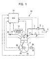
- an engine control system 50 of a 4-cycle internal combustion engine 3 for a vehicle is illustrated.
- the engine control system 50 employs a control system of a plunger-type fuel pump in accordance with the embodiment of the invention.
- the engine 3 has at least one cylinder with at least one fuel injector 4 and at least one intake port, and each cylinder has at least one spark plug 11, although only one cylinder, one fuel injector 4 and one spark plug are illustrated in Fig. 1 and the following description deals with the illustrated cylinder, fuel injector and spark plug only.
- An inlet line 1 of this internal combustion engine 3 is provided with a throttle valve 2, and an amount of intake air that corresponds to the opening degree of the throttle valve 2 is supplied via the inlet duct 1 to the intake port of the engine 3.
- the inlet duct 1 is provided with an injector 4 for fuel injection.
- the injector 4 is connected to a fuel supply pipe 7 from a fuel tank 6.
- the fuel supply pipe 7 is provided with a plunger-type fuel pump 8.
- This fuel pump 8 has, for example, a constitution as disclosed in Japanese Patent Kokai (Laid-open publication) No. 8-114179, the entire disclosure of which is incorporated herein by reference.
- the fuel pump 8 is driven by an ECU (electronic control unit) 10 such that the fuel pump 8 takes in fuel from the fuel tank 6 via the fuel supply pipe 7, and pumps the fuel via the fuel supply pipe 7 to the injector 4.
- the injector 4 is also driven by the ECU 10 such that the injector 4 injects the fuel towards the intake port.
- the spark plug 11 is fastened to the engine 3, and this spark plug 11 is connected to an ignition device 12.
- the ECU 10 induces a spark discharge in the cylinder of the engine 3.
- the ECU 10 includes an input interface circuit 20, an rpm counter (engine revolution speed sensor) 21, a CPU (central processing unit) 22, a memory 23, and driving circuits 24 and 25.
- the input interface circuit 20 is connected to engine operation parameter sensing means, such as a water temperature sensor 26 sensing the temperature of the engine cooling water, an intake pressure sensor 27 sensing a negative pressure in the intake duct 1, and an oxide concentration sensor 28.
- engine operation parameter sensing means such as a water temperature sensor 26 sensing the temperature of the engine cooling water, an intake pressure sensor 27 sensing a negative pressure in the intake duct 1, and an oxide concentration sensor 28.
- the oxide concentration sensor 28 is provided in an exhaust duct 13 and senses the oxide concentration in the exhaust gas.
- the rpm counter 21 is connected to a crank angle sensor 29 that senses the engine rpm.
- the crank angle sensor 29 generates a crank pulse every time a rotor (not shown) has rotated for a predetermined angle (for example 15 degrees) in cooperation with the rotation of a crank shaft 3a of the engine 3.
- a cam angle sensor 30 is provided in the vicinity of a cam shaft 3b.
- the cam angle sensor 30 outputs to the CPU 22 a TDC signal that indicates the piston in a representative cylinder (in the case of multiple-cylinder engine, the representative cylinder is a reference cylinder, and in the case of a single cylinder engine, it is that cylinder) is at the top dead center in the compression stroke of the piston.
- the cam angle sensor 30 also outputs a reference position signal to the CPU 22 every time the crank shaft 3a has rotated for 720 degrees.
- the rpm counter 21 After being reset by a crank pulse supplied from the crank angle sensor 29, the rpm counter 21 counts the clock pulses that are output from a clock generator (not shown) to generate a signal that indicates the engine rpm Ne.
- Sensor information about the cooling water temperature, the negative pressure in the intake line and the oxygen concentration provided by the sensors 26 to 28 is supplied to the CPU 22 from the input interface circuit 20.
- Information about the engine rpm is supplied to the CPU 22 from the rpm counter 21.
- the TDC signal and the reference position signal are supplied to the CPU 22 from the crank angle sensor 29.
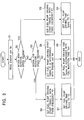
- the CPU 22 sets the fuel pump driving start timing t1, the fuel injection start timing t2 and the ignition time in synchronization with the reference position signal.
- the CPU 22 also calculates the fuel injection time Tout and the fuel pump driving time Tpump.
- the fuel pump driving start timing t1 and the fuel pump driving time Tpump are decided by a fuel pump driving setting routine (Fig. 3; will be described).
- a memory 23 stores operating programs of the CPU 22 and data.
- Ti is the basic fuel injection time (i.e., an air/fuel ratio reference control value) that is determined by referencing a data map in the memory 23 in accordance with the engine rpm and the negative pressure in the intake line.
- K O2 is an air/fuel ratio correction coefficient that is calculated in the air/fuel ratio feedback control, based on the signal provided from the oxygen concentration sensor 28.
- the CPU 22 reads in the engine rpm Ne from the value counted by the rpm counter 21 (step 1), and determines whether the engine rpm Ne is within a high rotation speed region (for example ⁇ 8400 rpm) (step S2). If the engine rpm Ne is within the high rotation speed region, then the fuel pump driving start timing t1 is set to a time in accordance with a fixed frequency F1 (for example 70 Hz) (step S3), and the fuel pump driving time Tpump is set to a predetermined time T1 (step S4).
- a high rotation speed region for example ⁇ 8400 rpm
- step S5 it is determined whether the engine rpm Ne is in a low rotation speed region (for example ⁇ 600 rpm) or not (step S5). If the engine rpm Ne is within the low rotation speed region, then the fuel pump driving start timing t1 is set to a time in accordance with a fixed frequency F2 (for example 20 Hz) (step S6), and the fuel pump driving time Tpump is set to a predetermined time T2 (step S7). If the engine rpm Ne is not within the low rotation speed region, then the fuel pump driving start timing t1 is set to a certain time by looking up the data map in the memory 23 in accordance with the engine rpm Ne (step S8). The fuel pump driving time Tpump (second predetermined time) is set by looking up the data map in the memory 23 in accordance with the fuel injection time Tout (step S9).
- a fixed frequency F2 for example 20 Hz
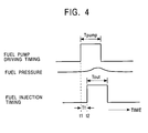
- the fuel pump driving start timing t1 of the step S8 is set to a timing that precedes the fuel injection start timing t2 by a time Tf (first predetermined time).
- the time Tf corresponds to the fuel pumping lag, and is determined in accordance with the engine rpm Ne. That is to say, the time Tf is set such that a rise in the fuel pressure due to the driving of the fuel pump 8 occurs during the fuel injection period (Tout), as shown in Fig. 4.
- step S8 the fuel injection start timing t2 that has been calculated in advance by the CPU 22 in a separate routine (not shown), and the time Tf that is obtained by looking up the data map are used to determine the fuel pump driving start timing t1.
- the timing of setting the time t1 will be described.
- the next fuel injection start timing t2 is calculated. Therefore, the time of deciding the fuel pump driving start timing t1 is after the calculation of the fuel injection starting timing t2 and sufficiently before the actual fuel injection starting timing t2 (that is, a time longer than a possibly maximum value of the time Tf should be reserved before the time t2).
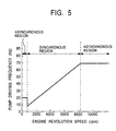
- the driving frequency of the fuel pump 8 becomes an fixed frequency that is asynchronous to the engine rpm in the low rotation speed region and the high rotation speed region, as shown in Fig. 5, and apart from those regions, it becomes a frequency that is synchronous to the injection driving.
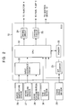
- Fig. 6 is now referred to.
- the CPU 22 determines, by interrupt processing for example, based on the crank pulse and the TDC signal or the reference position signal from the cam angle sensor 30, that the crank angle (which ranges from 0 degree to 720 degree) is in the angular position of the fuel pump driving start timing t1 (step S11), then the CPU 22 outputs a driving command indicating the fuel pump driving time Tpump to the driving circuit 25 (step S12). If the CPU 22 determines that the crank angle is in the angular position of the fuel injection start timing t2 (step S13), then the CPU 22 outputs a fuel injection command indicating the fuel injection time Tout to the driving circuit 24 (step S14). If the CPU 22 determines that the crank angle is in the angular position of the ignition period (step S15), then the CPU 22 outputs an ignition command to the ignition system 12 (step S16).
- the driving circuit 25 drives the fuel pump 8 for the fuel pump driving time Tpump starting at the fuel pump driving start timing t1.
- a predetermined power source voltage is applied to the fuel pump 8.
- the fuel pump 8 takes up the fuel from the fuel tank 6 via the fuel supply pipe 7 and pumps the fuel through the fuel supply pipe 7 to the injector 4. The pumping with the fuel pump 8 is performed for the fuel pump driving time Tpump.
- the driving circuit 24 drives the injector 4 for a fuel injection time Tout starting at the fuel injection start timing t2 in response to the fuel injection command, at a delay of the time Tf from the driving start timing t1 of the fuel pump 8.
- the injector 4 sprays the fuel toward the intake port of the engine 3 in the intake line 1.
- the fuel pump 8 is driven at a fixed frequency F2 that is greater than if the frequency were synchronized with the engine rpm Ne, so that the delay of the increase in fuel pressure when starting the engine disappears, and a sufficient fuel pressure increase can be caused. Consequently, it is possible to ensure stable combustion when starting the engine.
- the fuel pump 8 is driven at the fixed frequency F1, so that the amount of fuel discharged from the fuel pump 8 would not saturate, thereby preventing that the fuel pressure becomes unstable.
- the injector 4 is provided in the intake line 1 and injects the fuel into the intake line 1, but the injector 4 may inject the fuel directly into the cylinder of the engine 3. If the engine 3 has a plurality of cylinders, each cylinder may have an injector or all the cylinders may share a sole injector. In either case, the teaching of the present invention can be applicable.
- An internal combustion engine includes an injector that injects fuel into a cylinder.
- a plunger-type fuel pump pumps the fuel to the injector from a fuel tank.
- a control system for the fuel pump includes a unit for determining an injection start timing of the injector, and a drive unit for driving the fuel pump for a second predetermined time that starts a first predetermined time earlier than the injection start timing. This control system makes stable combustion possible even when there are pressure variations in the fuel pumped to the injector.
Landscapes
- Engineering & Computer Science (AREA)
- Chemical & Material Sciences (AREA)
- Combustion & Propulsion (AREA)
- Mechanical Engineering (AREA)
- General Engineering & Computer Science (AREA)
- Electrical Control Of Air Or Fuel Supplied To Internal-Combustion Engine (AREA)
- Fuel-Injection Apparatus (AREA)
- Control Of The Air-Fuel Ratio Of Carburetors (AREA)
- High-Pressure Fuel Injection Pump Control (AREA)
Abstract
Description
Claims (18)
- A control system for a plunger-type fuel pump in an internal combustion engine, the fuel pump pumping fuel to an injector from a fuel tank such that the injector can inject the fuel into a cylinder, the control system comprising:means for determining an injection start timing of the injector; anddriving means for driving the fuel pump for a second predetermined time that starts a first predetermined time earlier than the injection start timing.
- The control system according to claim 1, wherein the driving means comprises:means for detecting an engine rpm of the internal combustion engine;first setting means for setting the first predetermined time in accordance with the engine rpm; andsecond setting means for setting the second predetermined time in accordance with a fuel injection amount of the injector.
- The control system according to claim 1 or 2, wherein the driving means periodically drives the fuel pump at a first fixed frequency when the engine rpm is in a low rotation speed region; and
wherein the driving means periodically drives the fuel pump at a second fixed frequency, which is higher than the first fixed frequency, when the engine rpm is in a high rotation speed region. - The control system according to claim 3, wherein the engine rpm is in the low rotation speed region if the engine rpm is about 600 rpm or below.
- The control system according to claim 3 or 4, wherein the engine rpm is in the high rotation speed region if the engine rpm is about 8,400 rpm or more.
- The control system according to claim 3, 4 or 5, wherein the driving means drives the fuel pump at a frequency proportional to the engine rpm when the engine rpm is between the high rotation speed region and the low rotation speed region.
- The control system according to any one of claims 3 to 6, wherein the first fixed frequency is about 20Hz.
- The control system according to any one of claims 3 to 7, wherein the second fixed frequency is about 70Hz.
- A method of controlling a plunger-type fuel pump in an internal combustion engine, the fuel pump pumping fuel to an injector from a fuel tank such that the injector can inject the fuel into a cylinder, the method comprising:determining an injection start timing of the injector; anddriving the fuel pump for a second predetermined time that starts a first predetermined time earlier than the injection start timing.
- The method according to claim 9, wherein the driving the fuel pump comprises:detecting an engine rpm of the internal combustion engine;setting the first predetermined time in accordance with the engine rpm; andsetting the second predetermined time in accordance with a fuel injection amount of the injector.
- The method according to claim 9 or 10, wherein the driving the fuel pump comprises periodically driving the fuel pump at a first fixed frequency when the engine rpm is in a low rotation speed region.
- The method according to claim 9, 10 or 11, wherein the driving the fuel pump comprises periodically driving the fuel pump at a second fixed frequency when the engine rpm is in a high rotation speed region, the second fixed frequency being higher than the first fixed frequency.
- The method according to claim 11 or 12, wherein the driving the fuel pump comprises driving the fuel pump at a frequency proportional to the engine rpm when the engine rpm is between the high rotation speed region and the low rotation speed region.
- An apparatus for controlling a plunger-type fuel pump in an internal combustion engine, the fuel pump pumping fuel to an injector from a fuel tank such that the injector can inject the fuel into a cylinder, the apparatus comprising:a calculation unit for determining an injection start timing of the injector; anda drive unit for driving the fuel pump for a second predetermined time that starts a first predetermined time earlier than the injection start timing.
- The apparatus according to claim 14, wherein the drive unit comprises:an engine revolution speed sensor for detecting an engine rpm of the internal combustion engine;a first calculator for deciding the first predetermined time in accordance with the engine rpm; anda second calculator for deciding the second predetermined time in accordance with a fuel injection amount of the injector.
- The apparatus according to claim 14 or 15, wherein the drive unit periodically drives the fuel pump at a first fixed frequency when the engine rpm is in a low rotation speed region.
- The apparatus according to claim 14, 15 or 16, wherein the drive unit periodically drives the fuel pump at a second fixed frequency when the engine rpm is in a high rotation speed region, the second fixed frequency being higher than the first fixed frequency.
- The apparatus according to any one of claims 14 to 17, wherein the drive unit periodically drives the fuel pump at a frequency proportional to the engine rpm when the engine rpm is between the high rotation speed region and the low rotation speed region.
Applications Claiming Priority (2)
| Application Number | Priority Date | Filing Date | Title |
|---|---|---|---|
| JP2002208159A JP2004052596A (en) | 2002-07-17 | 2002-07-17 | Control device for plunger type fuel pump |
| JP2002208159 | 2002-07-17 |
Publications (3)
| Publication Number | Publication Date |
|---|---|
| EP1382825A2 true EP1382825A2 (en) | 2004-01-21 |
| EP1382825A3 EP1382825A3 (en) | 2004-04-14 |
| EP1382825B1 EP1382825B1 (en) | 2006-05-24 |
Family
ID=29774631
Family Applications (1)
| Application Number | Title | Priority Date | Filing Date |
|---|---|---|---|
| EP03013081A Expired - Lifetime EP1382825B1 (en) | 2002-07-17 | 2003-06-10 | Control system for plunger-type fuel pump |
Country Status (7)
| Country | Link |
|---|---|
| US (1) | US6820596B2 (en) |
| EP (1) | EP1382825B1 (en) |
| JP (1) | JP2004052596A (en) |
| CN (1) | CN1302203C (en) |
| AT (1) | ATE327422T1 (en) |
| DE (1) | DE60305387T8 (en) |
| TW (1) | TWI223028B (en) |
Cited By (2)
| Publication number | Priority date | Publication date | Assignee | Title |
|---|---|---|---|---|
| WO2015169467A1 (en) * | 2014-05-07 | 2015-11-12 | Robert Bosch Gmbh | Injection system and method for operating an injection system |
| EP3306061A4 (en) * | 2015-06-08 | 2019-01-16 | Mikuni Corporation | CONTROL DEVICE AND CONTROL METHOD FOR FUEL PUMP |
Families Citing this family (12)
| Publication number | Priority date | Publication date | Assignee | Title |
|---|---|---|---|---|
| JP2005307747A (en) * | 2004-04-16 | 2005-11-04 | Mitsubishi Electric Corp | Fuel supply device for internal combustion engine |
| DE102004020937B4 (en) * | 2004-04-28 | 2010-07-15 | Continental Automotive Gmbh | Method for determining a closing time of a closing element and circuit arrangement |
| DE102005008380A1 (en) * | 2005-02-23 | 2006-08-31 | Siemens Ag | Fuel supply for motor vehicle, has electrically propelled transfer pump arranged within fuel tank, where pressure side of transfer pump is connected with nozzles of ejector pumps, and transfers pump is discontinuously switched |
| DE102005043817A1 (en) * | 2005-09-13 | 2007-03-22 | Siemens Ag | Method for operating a fuel pump |
| DE102006033169B3 (en) * | 2006-07-10 | 2007-12-20 | Joma-Hydromechanic Gmbh | Flow rate-variable positive-displacement pump adjusting method for internal-combustion engine, involves changing flow rate of pump based on adjusting signal, and using signal of remaining oxygen content of probe as characteristic value |
| JP5095973B2 (en) * | 2006-09-25 | 2012-12-12 | 本田技研工業株式会社 | Fuel injection control device for various types of fuel engines |
| US7690353B2 (en) * | 2007-11-30 | 2010-04-06 | Caterpillar Inc. | Synchronizing common rail pumping events with engine operation |
| EP2096289A1 (en) * | 2008-02-29 | 2009-09-02 | Magneti Marelli Powertrain S.p.A. | Control method of an electronic injection fuel feeding system |
| JP5040884B2 (en) * | 2008-10-09 | 2012-10-03 | 株式会社デンソー | Fuel injection control device |
| DE102009027806A1 (en) * | 2009-07-17 | 2011-01-20 | Robert Bosch Gmbh | Method for operating fuel system of internal combustion engine, involves providing metering unit and fuel pump, where actuator of metering unit is controlled by periodically pulsed signal |
| JP4952754B2 (en) | 2009-08-12 | 2012-06-13 | セイコーエプソン株式会社 | Liquid ejecting apparatus, scalpel for operation, and method for controlling liquid ejecting apparatus |
| JP6973010B2 (en) * | 2017-12-13 | 2021-11-24 | トヨタ自動車株式会社 | Fuel pump controller |
Family Cites Families (11)
| Publication number | Priority date | Publication date | Assignee | Title |
|---|---|---|---|---|
| US3664311A (en) * | 1969-01-21 | 1972-05-23 | Nippon Denso Co | Fuel injection control system for internal combustion engine |
| US3646917A (en) * | 1970-06-16 | 1972-03-07 | Bendix Corp | Auxiliary circuit for electronic fuel control systems to facilitate cold starting |
| JP2576958B2 (en) * | 1987-09-28 | 1997-01-29 | 株式会社ゼクセル | Solenoid valve controlled distributed fuel injector |
| NZ222499A (en) * | 1987-11-10 | 1990-08-28 | Nz Government | Fuel injector pump: flow rate controlled by controlling relative phase of reciprocating piston pumps |
| JP2829639B2 (en) | 1989-09-22 | 1998-11-25 | 株式会社ゼクセル | Variable oil feed rate control method for electronically controlled distributed fuel injection pump |
| DE69332476T2 (en) | 1992-08-20 | 2003-05-08 | Toyota Jidosha K.K., Toyota | Fuel injection regulator for internal combustion engines. |
| US5755209A (en) | 1992-12-15 | 1998-05-26 | Robert Bosch Gmbh | System for controlling a fuel-metering device |
| JPH08114179A (en) | 1994-08-25 | 1996-05-07 | Mitsubishi Electric Corp | Electromagnetic pump and its control circuit |
| US5505180A (en) * | 1995-03-31 | 1996-04-09 | Ford Motor Company | Returnless fuel delivery mechanism with adaptive learning |
| JPH10318069A (en) * | 1997-05-20 | 1998-12-02 | Honda Motor Co Ltd | Drive device for fuel pump for motorcycles |
| JP3465641B2 (en) * | 1999-07-28 | 2003-11-10 | トヨタ自動車株式会社 | Fuel pump control device |
-
2002
- 2002-07-17 JP JP2002208159A patent/JP2004052596A/en not_active Withdrawn
-
2003
- 2003-06-05 TW TW092115255A patent/TWI223028B/en not_active IP Right Cessation
- 2003-06-05 US US10/454,589 patent/US6820596B2/en not_active Expired - Fee Related
- 2003-06-10 EP EP03013081A patent/EP1382825B1/en not_active Expired - Lifetime
- 2003-06-10 DE DE60305387T patent/DE60305387T8/en not_active Expired - Fee Related
- 2003-06-10 AT AT03013081T patent/ATE327422T1/en not_active IP Right Cessation
- 2003-06-30 CN CNB031452957A patent/CN1302203C/en not_active Expired - Fee Related
Cited By (2)
| Publication number | Priority date | Publication date | Assignee | Title |
|---|---|---|---|---|
| WO2015169467A1 (en) * | 2014-05-07 | 2015-11-12 | Robert Bosch Gmbh | Injection system and method for operating an injection system |
| EP3306061A4 (en) * | 2015-06-08 | 2019-01-16 | Mikuni Corporation | CONTROL DEVICE AND CONTROL METHOD FOR FUEL PUMP |
Also Published As
| Publication number | Publication date |
|---|---|
| CN1470754A (en) | 2004-01-28 |
| EP1382825A3 (en) | 2004-04-14 |
| EP1382825B1 (en) | 2006-05-24 |
| US20040011335A1 (en) | 2004-01-22 |
| TWI223028B (en) | 2004-11-01 |
| CN1302203C (en) | 2007-02-28 |
| US6820596B2 (en) | 2004-11-23 |
| ATE327422T1 (en) | 2006-06-15 |
| TW200401864A (en) | 2004-02-01 |
| DE60305387T2 (en) | 2006-09-28 |
| DE60305387D1 (en) | 2006-06-29 |
| JP2004052596A (en) | 2004-02-19 |
| DE60305387T8 (en) | 2007-03-08 |
Similar Documents
| Publication | Publication Date | Title |
|---|---|---|
| US6820596B2 (en) | Control system for plunger-type fuel pump | |
| EP3722580B1 (en) | Control system for internal combustion engine, and internal combustion engine | |
| JP2005307747A (en) | Fuel supply device for internal combustion engine | |
| EP3722579B1 (en) | Control system for internal combustion engine, and internal combustion engine | |
| JP2001152936A (en) | Engine fuel injection control device | |
| JP2005048659A (en) | Fuel temperature estimation device | |
| US7155330B2 (en) | Cam sensor elimination in compression-ignition engines | |
| JPS6255436A (en) | Fuel injection quantity controller for diesel engine | |
| CN111810310B (en) | Control systems and internal combustion engines for internal combustion engines | |
| JP5381747B2 (en) | Fuel injection device | |
| JPH1018884A (en) | Fuel supply system for direct injection type internal combustion engine | |
| JPH10246138A (en) | Fuel injection control device for in-cylinder direct injection spark ignition internal combustion engine | |
| JP4826300B2 (en) | Control device and control method for internal combustion engine | |
| JP3512932B2 (en) | Fuel supply control device for internal combustion engine | |
| JP2001041082A (en) | Common rail fuel injection control device | |
| JP2004340041A (en) | Fuel injection device including fuel pump | |
| JPH109074A (en) | Direct in-cylinder injection spark ignition engine | |
| JP2004340042A (en) | Fuel injection device including fuel pump | |
| JP2008051000A (en) | Fuel injection control device and method | |
| JP2003138961A (en) | Start control device for internal combustion engine | |
| KR100226642B1 (en) | Fuel injection control device | |
| JP2004340043A (en) | Fuel injection device including fuel pump | |
| JPH08177587A (en) | Fuel injection control device for diesel engine | |
| JPS6098147A (en) | Fuel injection control method of electronically controlled diesel engine | |
| JPS6035156A (en) | Fuel injection device for internal-combustion engine |
Legal Events
| Date | Code | Title | Description |
|---|---|---|---|
| PUAI | Public reference made under article 153(3) epc to a published international application that has entered the european phase |
Free format text: ORIGINAL CODE: 0009012 |
|
| AK | Designated contracting states |
Kind code of ref document: A2 Designated state(s): AT BE BG CH CY CZ DE DK EE ES FI FR GB GR HU IE IT LI LU MC NL PT RO SE SI SK TR |
|
| AX | Request for extension of the european patent |
Extension state: AL LT LV MK |
|
| PUAL | Search report despatched |
Free format text: ORIGINAL CODE: 0009013 |
|
| AK | Designated contracting states |
Kind code of ref document: A3 Designated state(s): AT BE BG CH CY CZ DE DK EE ES FI FR GB GR HU IE IT LI LU MC NL PT RO SE SI SK TR |
|
| AX | Request for extension of the european patent |
Extension state: AL LT LV MK |
|
| RIC1 | Information provided on ipc code assigned before grant |
Ipc: 7F 02D 41/30 A Ipc: 7F 02D 41/36 B Ipc: 7F 02D 41/40 B |
|
| 17P | Request for examination filed |
Effective date: 20040525 |
|
| 17Q | First examination report despatched |
Effective date: 20040713 |
|
| AKX | Designation fees paid |
Designated state(s): AT DE FR GB IT |
|
| GRAP | Despatch of communication of intention to grant a patent |
Free format text: ORIGINAL CODE: EPIDOSNIGR1 |
|
| GRAS | Grant fee paid |
Free format text: ORIGINAL CODE: EPIDOSNIGR3 |
|
| GRAA | (expected) grant |
Free format text: ORIGINAL CODE: 0009210 |
|
| AK | Designated contracting states |
Kind code of ref document: B1 Designated state(s): AT DE FR GB IT |
|
| REG | Reference to a national code |
Ref country code: GB Ref legal event code: FG4D |
|
| REF | Corresponds to: |
Ref document number: 60305387 Country of ref document: DE Date of ref document: 20060629 Kind code of ref document: P |
|
| ET | Fr: translation filed | ||
| PLBE | No opposition filed within time limit |
Free format text: ORIGINAL CODE: 0009261 |
|
| STAA | Information on the status of an ep patent application or granted ep patent |
Free format text: STATUS: NO OPPOSITION FILED WITHIN TIME LIMIT |
|
| 26N | No opposition filed |
Effective date: 20070227 |
|
| PGFP | Annual fee paid to national office [announced via postgrant information from national office to epo] |
Ref country code: AT Payment date: 20080616 Year of fee payment: 6 |
|
| PGFP | Annual fee paid to national office [announced via postgrant information from national office to epo] |
Ref country code: IT Payment date: 20080621 Year of fee payment: 6 |
|
| PGFP | Annual fee paid to national office [announced via postgrant information from national office to epo] |
Ref country code: DE Payment date: 20080430 Year of fee payment: 6 |
|
| PGFP | Annual fee paid to national office [announced via postgrant information from national office to epo] |
Ref country code: FR Payment date: 20080613 Year of fee payment: 6 |
|
| PGFP | Annual fee paid to national office [announced via postgrant information from national office to epo] |
Ref country code: GB Payment date: 20080620 Year of fee payment: 6 |
|
| GBPC | Gb: european patent ceased through non-payment of renewal fee |
Effective date: 20090610 |
|
| REG | Reference to a national code |
Ref country code: FR Ref legal event code: ST Effective date: 20100226 |
|
| PG25 | Lapsed in a contracting state [announced via postgrant information from national office to epo] |
Ref country code: FR Free format text: LAPSE BECAUSE OF NON-PAYMENT OF DUE FEES Effective date: 20090630 |
|
| PG25 | Lapsed in a contracting state [announced via postgrant information from national office to epo] |
Ref country code: GB Free format text: LAPSE BECAUSE OF NON-PAYMENT OF DUE FEES Effective date: 20090610 |
|
| PG25 | Lapsed in a contracting state [announced via postgrant information from national office to epo] |
Ref country code: DE Free format text: LAPSE BECAUSE OF NON-PAYMENT OF DUE FEES Effective date: 20100101 Ref country code: AT Free format text: LAPSE BECAUSE OF NON-PAYMENT OF DUE FEES Effective date: 20090610 |
|
| PG25 | Lapsed in a contracting state [announced via postgrant information from national office to epo] |
Ref country code: IT Free format text: LAPSE BECAUSE OF NON-PAYMENT OF DUE FEES Effective date: 20090610 |