EP1382802A1 - Démarreur-générateur intégré pour turbomachine - Google Patents
Démarreur-générateur intégré pour turbomachine Download PDFInfo
- Publication number
- EP1382802A1 EP1382802A1 EP03291735A EP03291735A EP1382802A1 EP 1382802 A1 EP1382802 A1 EP 1382802A1 EP 03291735 A EP03291735 A EP 03291735A EP 03291735 A EP03291735 A EP 03291735A EP 1382802 A1 EP1382802 A1 EP 1382802A1
- Authority
- EP
- European Patent Office
- Prior art keywords
- compressor
- rotor
- chamber
- generator
- turbomachine
- Prior art date
- Legal status (The legal status is an assumption and is not a legal conclusion. Google has not performed a legal analysis and makes no representation as to the accuracy of the status listed.)
- Granted
Links
Images



Classifications
-
- H—ELECTRICITY
- H02—GENERATION; CONVERSION OR DISTRIBUTION OF ELECTRIC POWER
- H02K—DYNAMO-ELECTRIC MACHINES
- H02K7/00—Arrangements for handling mechanical energy structurally associated with dynamo-electric machines, e.g. structural association with mechanical driving motors or auxiliary dynamo-electric machines
- H02K7/18—Structural association of electric generators with mechanical driving motors, e.g. with turbines
- H02K7/1807—Rotary generators
- H02K7/1823—Rotary generators structurally associated with turbines or similar engines
-
- F—MECHANICAL ENGINEERING; LIGHTING; HEATING; WEAPONS; BLASTING
- F01—MACHINES OR ENGINES IN GENERAL; ENGINE PLANTS IN GENERAL; STEAM ENGINES
- F01D—NON-POSITIVE DISPLACEMENT MACHINES OR ENGINES, e.g. STEAM TURBINES
- F01D15/00—Adaptations of machines or engines for special use; Combinations of engines with devices driven thereby
- F01D15/10—Adaptations for driving, or combinations with, electric generators
-
- F—MECHANICAL ENGINEERING; LIGHTING; HEATING; WEAPONS; BLASTING
- F02—COMBUSTION ENGINES; HOT-GAS OR COMBUSTION-PRODUCT ENGINE PLANTS
- F02C—GAS-TURBINE PLANTS; AIR INTAKES FOR JET-PROPULSION PLANTS; CONTROLLING FUEL SUPPLY IN AIR-BREATHING JET-PROPULSION PLANTS
- F02C7/00—Features, components parts, details or accessories, not provided for in, or of interest apart form groups F02C1/00 - F02C6/00; Air intakes for jet-propulsion plants
- F02C7/26—Starting; Ignition
- F02C7/268—Starting drives for the rotor, acting directly on the rotor of the gas turbine to be started
-
- F—MECHANICAL ENGINEERING; LIGHTING; HEATING; WEAPONS; BLASTING
- F02—COMBUSTION ENGINES; HOT-GAS OR COMBUSTION-PRODUCT ENGINE PLANTS
- F02C—GAS-TURBINE PLANTS; AIR INTAKES FOR JET-PROPULSION PLANTS; CONTROLLING FUEL SUPPLY IN AIR-BREATHING JET-PROPULSION PLANTS
- F02C7/00—Features, components parts, details or accessories, not provided for in, or of interest apart form groups F02C1/00 - F02C6/00; Air intakes for jet-propulsion plants
- F02C7/32—Arrangement, mounting, or driving, of auxiliaries
-
- H—ELECTRICITY
- H02—GENERATION; CONVERSION OR DISTRIBUTION OF ELECTRIC POWER
- H02K—DYNAMO-ELECTRIC MACHINES
- H02K7/00—Arrangements for handling mechanical energy structurally associated with dynamo-electric machines, e.g. structural association with mechanical driving motors or auxiliary dynamo-electric machines
- H02K7/14—Structural association with mechanical loads, e.g. with hand-held machine tools or fans
-
- Y—GENERAL TAGGING OF NEW TECHNOLOGICAL DEVELOPMENTS; GENERAL TAGGING OF CROSS-SECTIONAL TECHNOLOGIES SPANNING OVER SEVERAL SECTIONS OF THE IPC; TECHNICAL SUBJECTS COVERED BY FORMER USPC CROSS-REFERENCE ART COLLECTIONS [XRACs] AND DIGESTS
- Y02—TECHNOLOGIES OR APPLICATIONS FOR MITIGATION OR ADAPTATION AGAINST CLIMATE CHANGE
- Y02T—CLIMATE CHANGE MITIGATION TECHNOLOGIES RELATED TO TRANSPORTATION
- Y02T50/00—Aeronautics or air transport
- Y02T50/60—Efficient propulsion technologies, e.g. for aircraft
Definitions
- the invention relates to an aviation turbine engine and more particularly a turbomachine comprising a current generator integrated electrical coaxial to the axis of the turbomachine.
- the accessory box equipped of fuel pumps, bearing lubrication pumps, pumps hydraulics for the control of various organs, generators and starter motor is placed outside the engine and receives the power extracted from the engine by means of a vertical shaft and references angles.
- the power take-off chain and the case accessories have followed this difficulty with difficulty and still represent a significant part of the volume and mass of engines, especially when they are of low thrust, small size, especially when this accessory case, usually placed under or on the engine, sometimes laterally to it, supports a air starter and a separate electric generator.
- auxiliary generators which increases the size housings, as well as their mass to support them. It is therefore interesting to integrate an auxiliary generator, in addition to the generator-starter in the engine, in a motor with a high dilution ratio, in order to reduce the size and mass of cross references, or even remove them, and to thin the basket, housing some accessories at training electric in the pylon.
- US Pat. No. 3,859,785 relates to a single-engine turbomachine, in which a bell with permanent magnets forms the rotor of a generator and serves as a nut at the front bearing of the compressor shaft. This bell is disposed in the air intake cone of the compressor.
- This solution has the disadvantage of limiting in size the generator of current due to the small diameters of the shaft and inlet cone. This compressor must turn at high speeds to deliver a high power in such a small footprint.
- US Pat. No. 5,867,979 relates to a turbomachine with a high dilution that has three bodies.
- This document shows in Figure 1, a main current generator arranged coaxially in the rear cone low pressure turbine, that is to say in a hot zone, and auxiliary generators arranged in the crankcase and driven by angle references and transverse shafts, these auxiliary generators receiving power respectively from the high-pressure shaft and the shaft of the intermediate body.
- FIGS. 2 and 3 illustrate a second mode of embodiment, illustrated in FIGS. 2 and 3, in which the front and rear of the trees are electromagnetic type and incorporate electric generators. Because these generators are integrated on the trees, their dimensioning is reduced and they have to turn to a high speed to deliver significant power in a congestion also reduced.
- the built-in generators on Rear bearings are arranged in hot areas.
- US 3,264,482 shows a double-body double-shaft turbomachine flow which comprises a starter generator interposed between a fixed disk and the support bearing of the compressor rotor on the drive shaft of the blower.
- the inductor is mounted on the periphery of a rotor disk surrounding a sleeve provided at the front of the compressor rotor, and the support by the inter-shaft bearing, and the armature is mounted inside the motor housing.
- the rotor disk of the starter generator is bulky and causes a noticeable increase in mass.
- GB 1,147,730 represents the state of the art closest of the invention, because it shows in Figure 3 an electric starter which the inductor is mounted in the bore of a blisk 32 of a rotor of compressor and surrounds the integral armature of the compressor stator, without excessive mass increase, this starter can also be used as an electricity generator.
- the object of the invention is to propose a turbomachine having at least one current generator built-in electric that can produce significant power at low speed.
- This object is achieved by the invention by integrating the generator in a cold zone with a diameter much larger than that of a shaft or a shaft bearing of said turbomachine, and in a zone to ensure a greater axial extent of the air gap.
- the invention therefore relates to a turbomachine comprising a combustion chamber and a high pressure body, said body having, upstream of said chamber, an axial X-axis compressor intended to deliver air to said chamber and, downstream of said chamber, a turbine receiving hot gases from said chamber and intended for rotate the rotor of said compressor, said compressor having a plurality of compression stages, each stage having a ring of fixed vanes integral with a housing and a crown of moving blades which extend radially to the periphery of a disc of said rotor, said turbomachine further comprising a electrical current generator coaxial to said body and whose inductor is integral in rotation with said rotor and whose armature is integral with said casing, the inductor being mounted in the bore of at least one disc of said compressor and surrounding the armature, and the generator being configured to operate as a starter.
- this turbomachine is characterized by the fact that the compressor comprises at minus one disc having large-rope blades, and the inductor is mounted in the bore of said disk.
- the inductor is mounted in the bore of the two-stage disks consecutive compressor.
- the generator is integrated upstream of the compressor, that is to say in the bore of the disk closest to the support inlet casing armature, the 1 st floor, advantageously a monobloc blisk.
- the generator is integrated downstream of the compressor, that is to say in the bore of the discs closest to the intermediate support casing armature.
- the generator is always integrated upstream of the high-pressure compressor, that is to say in the bore of the disc or discs, the nearest one or the intermediate casing, preferably discs or rings bladed monoblocks.
- a double-body turbomachine with in addition a low pressure body having a low pressure compressor disposed upstream of the high pressure body, and a low pressure turbine disposed downstream of the high pressure body and intended to drive rotating the rotor of said low pressure compressor, said compressor having a plurality of compression stages each having a crown of fixed blades and a crown of moving blades that extend radially at the periphery of a disk of said rotor, it is furthermore advantage of equipping this turbomachine with an auxiliary generator of current of which the inductor is mounted in the bore of at least one disk of the low pressure compressor.
- the provisions of the invention make it possible to envisage a aviation turbine engine in which the accessories are driven by electric motors powered by current generators according to the invention, and thus to suppress the mechanical links and the references angles, to lighten the engine and to thin the basket in the case of a turbojet engine with high dilution ratio.
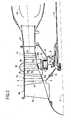
- Figure 1 shows the front part of a turbomachine unibody 1 with inlet housing that includes, at the front of the chamber not shown in the drawing, an axial compressor 2 of X axis, whose rotor 3 is driven by the rotor of a turbine which transforms a part of the energy of the hot gases from the combustion chamber in work of compressing the air that enters the compressor 2 by the front, this compressed air being delivered into the combustion chamber where fuel is injected and burned.
- the other part of the energy of the gases of the combustion chamber serves for the propulsion of the aircraft equipped with said turbomachine.
- the compressor has several stages of compression. Each stage comprises a ring 5 of fixed blades 6 which extend radially inwardly from the outer casing 7 of the engine, and a crown 8 of blades 9, arranged downstream of the blade crown 5 6, which extend radially outwardly from the periphery of a disk 10 forming a constituent element of the rotor 3.
- the first stage of the compressor 2 shown in FIG. comprises vanes 6 constituted at the front by structural arms 11 and formed at the rear by pivoting wings 12 whose angle is adjusted according to the rotational speed of the rotor 3, in order to improve the efficiency of the turbomachine.
- the structural arms 11 extend radially outwardly from a support structure 13 of the front bearing 14 of the compressor 2.
- the blades 9 of the first stage are of the big rope type, and the corresponding disk 10 has a large axial dimension. This disc 10 is connected to a ferrule 15 at the front end of which is mounted the front bearing 14.
- a generator-starter 20, of axis X is mounted in the annular space 21 delimited by the ferrule 15, the structure of support 13 of the bearing 14 and the disc 10 of the first stage.
- the inductor 22 of this generator-starter 20 is mounted in the inner bore 23 of the disc 10 and surrounds the armature 24 which is mounted on a cylindrical shell 35 secured to the support structure 13 of the bearing 14.
- the poles of the inductor 22 consist of rare earth magnets, Samarium-Cobalt by example, whose characteristics fall only slightly temperature of 300 ° C, and serve as a permanent source of field magnetic.
- These magnets 25 are evenly distributed on the face internal of a cylindrical sleeve 26 made of magnetic material at high resistance, from maraging for example, to form the inductor of the generator-starter 20.
- These permanent magnets 25, of high energy are unlikely to demagnetize and do not generate currents of Foucault. They do not need forced cooling in the front environment of the compressor 2.
- Blocks 27 made of resin or aluminum are glued between the magnets 25 to fill the void of interpolar spaces and ensure the cohesion of the inductor.
- spacer 28 of small thickness of non-magnetic material, glued and fretted, ensures the maintenance of permanent magnets 25 in the sleeve cylindrical 26 and protects the active parts of the inductor 22 at the level of the generator-starter air gap 20.
- the cylindrical sleeve 26, completely equipped, is placed in the bore 23 of the disc 10 of the first stage of the compressor 2. It is locked in rotation by teeth or grooves 29 and retained axially by a flexible ring 30 mounted in a groove in the disc 10, as shown in FIG. 1.
- the cylindrical sleeve 26 plays the role of fret and allows to ensure an interface proper to the assembly and disassembly of the inductor 22 in the bore 23 of the disk 10.
- the thickness of the cylindrical sleeve 26, necessary for close the magnetic flux, must be sufficient to centrifugal forces developed by the permanent magnets 25 and the nonmagnetic spacer 28 during rotation of the rotor 3.
- the sleeve cylindrical 26 thus ensures the mechanical and magnetic functions.
- the disk 10 of the compressor 2 is therefore sized to resist the aerodynamic and centrifugal forces of the blades 9 but also to those due to the presence of the inductor 22 in its bore 23.
- the magnetic circuit of the armature 24 is constituted so classic by stacking very low iron-silicon sheets thickness to limit the flow of eddy currents and by coils 31 wound around the armature poles 32 thus created.
- the armature 24 is mounted around the cylindrical shell 35 which extends axially rearwardly from the support structure 13 of the bearing 14.
- the cylindrical shell 35 has a diameter greater than the diameter of the outer ring of the bearing 14. This arrangement facilitates the maintenance and removing the armature 24.
- the structure 13 and the cylindrical shell 35 may be provided with channels and recesses 36 which serve to circulation of a cooling fluid able to evacuate the calories produced according to techniques well known in the field of the art.
- the electrical energy delivered by the generator 20 being alternative and at a high and variable frequency, proportional to engine speed, all or part of this energy is rectified.
- the other part can be used directly without an electronic interface with the network of the machine or aircraft equipped with the turbomachine according to the invention.
- the generator 20 supplies the electrical energy to the whole of the network, aircraft and engine.
- any use of broom, on collector or ring, is removed, which can only improve reliability and maintenance.
- Light and reliable fuses, located outside the engine, can limit the electrical power generated in the event of a short circuit windings 31, caused by the permanent magnets 25, in order to avoid the destruction of the electrical system.
- FIG. 2 shows another type of one-piece turbomachine without an inlet casing in which the compressor 2 is separated from the combustion chamber 40 by an intermediate casing 41.
- This housing intermediate is extended forward by the outer casing 7 of the compressor 2 from which extend radially inward three rings 5a, 5b, 5c of fixed blades referenced 6a, 6b, 6c.
- the rotor 3 of compressor 2 has three rings 8a, 8b, 8c of blades 9a, 9b, 9c.
- the blade crown of each stage is disposed upstream of the blade crown of the same floor.
- the rotor 3 is connected to the turbine disposed downstream of the chamber 40 by a shaft 42 of X axis connected to the rotor 3, downstream of the first ring 8a of blades 9a, by a conical shell 15.
- the front end of the shaft 42 is supported by a bearing 14, itself supported by a support structure 13, also conical connected to the intermediate casing 41.
- the movable blades 9a of the first stage are large-rope type, while the blades 9b and 9c have a much smaller axial dimension and are mounted at the periphery of two adjacent disks 10a, 10b arranged in the annular space 21 delimited by the ferrule 15 and the rotor 3.
- a generator-starter 20 similar to that described in reference to FIGS. 1 and 4, comprises an inductor 22 arranged in internal bores of the two adjacent disks 10a and 10b, and an armature 24 mounted around a cylindrical shell 35 integral with the structure of support 13 of the bearing 14.
- Figure 3 shows the front part of a double turbojet double flow body which has a blower 50 from front to back driven by a shaft 51 at low pressure of axis X, a compressor with low pressure 52 driven by the same low pressure shaft 51, a intermediate casing 53, and a high pressure compressor 2 driven by a high pressure tree.
- a bearing 14 is interposed between a structure support 13 connected to the intermediate casing 53 and the front end of the high pressure shaft.
- An X axis generator-starter 20 is integrated into the space ring 21 delimited by the support structure 13, the rotor of the high pressure compressor 2 and a ferrule 15 secured to the high shaft pressure.
- This generator-starter is similar to the one described above and does not require further explanation.
- the front end of the low pressure shaft 51 is connected to the impeller 50 by a conical shell 15a and is supported by a front bearing 60 itself supported by a conical structure 61 connected to the intermediate casing 53.
- the rotor 62 of the low-pressure compressor 52 is connected to the impeller 50 and is constituted by a plurality of discs 63 on the periphery of which lie blade crowns movable interposed between fixed blade crowns secured to a front casing 64.
- an auxiliary generator 65 or auxiliary, X axis is integrated in the annular space 66 delimited by the ferrule 15a, the rotor 62 and the conical structure 61.
- This auxiliary generator 65 shown in FIG. detail in Figure 6, has a structure similar to that of the generator-starter Described above. Its inductor 22 is mounted in the bore of a disc 63 of the low pressure compressor 52, and its armature 24 is mounted around a cylindrical shell 67 integral with the conical structure 61.
- FIG. 5 shows the twin-turbojet turbojet engine described above mounted under the wing 70 of an aircraft.
- the fuel pump low pressure 71 is disposed in the pylon, and the fuel pump 72 high pressure is installed in the crankcase.
- These two pumps 71 and 72 are driven by electric motors powered by the generator-starter 20 and possibly by the auxiliary generator 65.
- This "all-electric" turbojet engine no longer includes the referral or a case of accessories arranged in the basket 73.
- variable reluctance technology that combines a reliable rotor without coil or magnets but a simple inductor denté which forms the poles, with a high power density and a good tolerance to high temperature.
Landscapes
- Engineering & Computer Science (AREA)
- Chemical & Material Sciences (AREA)
- Combustion & Propulsion (AREA)
- Mechanical Engineering (AREA)
- General Engineering & Computer Science (AREA)
- Power Engineering (AREA)
- Structures Of Non-Positive Displacement Pumps (AREA)
- Connection Of Motors, Electrical Generators, Mechanical Devices, And The Like (AREA)
Abstract
Description
- la figure 1 est une demi-coupe schématique de l'avant d'une turbomachine monocorps avec carter d'entrée qui montre la disposition d'un générateur-démarreur intégré selon l'invention ;
- la figure 2 est semblable à la figure 1 et montre la disposition du générateur-démarreur selon l'invention sur une turbomachine monocorps sans carter d'entrée ;
- la figure 3 est une demi-coupe schématique d'une turbomachine double corps, double flux, dont le compresseur haute pression est équipé d'un générateur-démarreur selon l'invention, et dont le compresseur basse pression est équipé d'un générateur auxiliaire selon l'invention ;
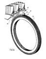
- la figure 4 est une coupe selon un plan perpendiculaire à l'axe du moteur d'un générateur de courant selon l'invention ;
- la figure 5 montre un exemple de la disposition des accessoires dans un turboréacteur "tout électrique" ; et
- la figure 6 est une coupe schématique d'un compresseur basse pression équipé d'un générateur auxiliaire.
Claims (5)
- Turbomachine comportant une chambre de combustion et un corps haute pression, ledit corps présentant, en amont de ladite chambre, un compresseur axial (2) d'axe X destiné à délivrer de l'air à ladite chambre et, en aval de ladite chambre, une turbine recevant des gaz chauds de ladite chambre et destinée à entraíner en rotation le rotor (3) dudit compresseur (2), ledit compresseur comportant une pluralité d'étages de compression, chaque étage présentant une couronne d'aubes fixes solidaires d'un carter et une couronne d'aubes mobiles qui s'étendent radialement à la périphérie d'un disque dudit rotor, ladite turbomachine comportant en outre un générateur (20) de courant électrique coaxial audit corps et dont l'inducteur est solidaire en rotation dudit rotor et dont l'induit est solidaire dudit carter, l'inducteur (22) étant monté dans l'alésage (23) d'au moins un disque (10) dudit compresseur (2) et entourant l'induit (24) et le générateur (20) étant configuré pour fonctionner en tant que démarreur de ladite turbomachine,
caractérisé par le fait que le compresseur (2) comporte au moins un disque portant des aubes mobiles à grande corde, et l'inducteur (22) est monté dans l'alésage dudit disque. - Turbomachine comportant une chambre de combustion et un corps haute pression, ledit corps présentant, en amont de ladite chambre, un compresseur axial (2) d'axe X destiné à délivrer de l'air à ladite chambre et, en aval de ladite chambre, une turbine recevant des gaz chauds de ladite chambre et destinée à entraíner en rotation le rotor (3) dudit compresseur (2), ledit compresseur comportant une pluralité d'étages de compression, chaque étage présentant une couronne d'aubes fixes solidaires d'un carter et une couronne d'aubes mobiles qui s'étendent radialement à la périphérie d'un disque dudit rotor, ladite turbomachine comportant en outre un générateur (20) de courant électrique coaxial audit corps et dont l'inducteur est solidaire en rotation dudit rotor et dont l'induit est solidaire dudit carter,
caractérisée par le fait que l'inducteur (22) est monté dans l'alésage des disques de deux étages consécutifs du compresseur. - Turbomachine selon l'une des revendications 1 ou 2, comportant en outre un corps basse pression ayant un compresseur basse pression (52) disposé en amont du corps haute pression, et une turbine basse pression disposée en aval du corps haute pression et destinée à entraíner en rotation le rotor (62) dudit compresseur basse pression, ledit compresseur comportant une pluralité d'étages de compression présentant chacun une couronne d'aubes fixes et une couronne d'aubes mobiles qui s'étendent radialement à la périphérie d'un disque (63) dudit rotor,
caractérisée par le fait qu'elle comporte en outre un générateur auxiliaire (65) de courant dont l'inducteur (22) est monté dans l'alésage intérieur d'au moins un disque (63) du compresseur à basse pression. - Turbomachine selon l'une quelconque des revendications 1 à 3, caractérisée par le fait que l'induit est monté autour d'une virole cylindrique (35, 67) prévue sur la structure de support (13, 61) d'un palier (14, 60) du compresseur correspondant.
- Turbomachine selon la revendication 4, caractérisée par le fait que la virole cylindrique (35, 67) a un diamètre supérieur au diamètre de la bague extérieure du palier (14, 60).
Applications Claiming Priority (2)
| Application Number | Priority Date | Filing Date | Title |
|---|---|---|---|
| FR0209029 | 2002-07-17 | ||
| FR0209029A FR2842565B1 (fr) | 2002-07-17 | 2002-07-17 | Demarreur-generateur integre pour turbomachine |
Publications (2)
| Publication Number | Publication Date |
|---|---|
| EP1382802A1 true EP1382802A1 (fr) | 2004-01-21 |
| EP1382802B1 EP1382802B1 (fr) | 2008-12-03 |
Family
ID=29763899
Family Applications (1)
| Application Number | Title | Priority Date | Filing Date |
|---|---|---|---|
| EP03291735A Expired - Lifetime EP1382802B1 (fr) | 2002-07-17 | 2003-07-11 | Démarreur-générateur intégré pour turbomachine |
Country Status (5)
| Country | Link |
|---|---|
| US (1) | US6914344B2 (fr) |
| EP (1) | EP1382802B1 (fr) |
| DE (1) | DE60324993D1 (fr) |
| FR (1) | FR2842565B1 (fr) |
| RU (1) | RU2321755C2 (fr) |
Cited By (12)
| Publication number | Priority date | Publication date | Assignee | Title |
|---|---|---|---|---|
| EP1614855A1 (fr) * | 2004-07-05 | 2006-01-11 | Siemens Aktiengesellschaft | Turbomachine et procédé d'utilisation de celle-ci |
| FR2878286A1 (fr) * | 2004-11-25 | 2006-05-26 | Snecma Moteurs Sa | Turbomachine comportant un generateur de courant electrique integre |
| WO2007036202A1 (fr) * | 2005-09-28 | 2007-04-05 | Mtu Aero Engines Gmbh | Moteur a reaction a unite moteur/generateur electrique integree |
| ES2285898A1 (es) * | 2005-04-11 | 2007-11-16 | Maria Elena Novo Vidal | Generador electrico accionado por turbinas. |
| RU2406829C2 (ru) * | 2006-01-24 | 2010-12-20 | Снекма | Газотурбинный двигатель и стартер-генератор для газотурбинного двигателя |
| WO2011127901A1 (fr) * | 2010-04-14 | 2011-10-20 | Mtu Aero Engines Gmbh | Groupe motopropulseur à plusieurs corps présentant un générateur tandem |
| RU2445481C2 (ru) * | 2007-01-31 | 2012-03-20 | Испано-Сюиза | Распределенная архитектура газотурбинного стартер-генератора |
| WO2020084225A1 (fr) | 2018-10-26 | 2020-04-30 | Safran Aircraft Engines | Module de soufflante equipe d'une machine electrique pour une turbomachine d'aeronef |
| WO2020084241A1 (fr) | 2018-10-26 | 2020-04-30 | Safran Aircraft Engines | Turbomachine d'aeronef equipee d'une machine electrique |
| WO2020084219A1 (fr) | 2018-10-26 | 2020-04-30 | Safran Aircraft Engines | Turbomachine d'aeronef equipee d'une machine electrique |
| WO2021181031A1 (fr) | 2020-03-10 | 2021-09-16 | Safran Aircraft Engines | Module de turbomachine equipe d'un rotor de machine electrique |
| FR3129970A1 (fr) * | 2021-12-02 | 2023-06-09 | Safran Aircraft Engines | Turbomachine comprenant une machine électrique en aval d’un arbre de turbine et entraînée par cet arbre |
Families Citing this family (118)
| Publication number | Priority date | Publication date | Assignee | Title |
|---|---|---|---|---|
| DE10359559A1 (de) * | 2003-12-18 | 2005-07-28 | Mtu Aero Engines Gmbh | Gasturbine, insbesondere Flugtriebwerk |
| FR2865002B1 (fr) * | 2004-01-12 | 2006-05-05 | Snecma Moteurs | Turboreacteur a double flux comprenant un support de distribution de servitudes et le support de distribution de servitudes. |
| US7285871B2 (en) * | 2004-08-25 | 2007-10-23 | Honeywell International, Inc. | Engine power extraction control system |
| RU2283963C2 (ru) * | 2004-09-21 | 2006-09-20 | Михаил Иванович Новиков | Газотурбинный двигатель с электростартером |
| FR2878287B1 (fr) * | 2004-11-25 | 2009-05-22 | Snecma Moteurs Sa | Turboreacteur double corps double flux avec generateur de courant electrique arriere |
| US7934902B2 (en) | 2004-12-01 | 2011-05-03 | United Technologies Corporation | Compressor variable stage remote actuation for turbine engine |
| WO2006059985A1 (fr) | 2004-12-01 | 2006-06-08 | United Technologies Corporation | Compresseur axial pour moteur a turbine de bout |
| WO2006110124A2 (fr) * | 2004-12-01 | 2006-10-19 | United Technologies Corporation | Refroidissement par ejecteur de l'enveloppe exterieure d'un moteur a turbine de bout |
| EP1841959B1 (fr) | 2004-12-01 | 2012-05-09 | United Technologies Corporation | Ailettes de rotor de soufflante pour moteur a turbine en bout |
| EP1828547B1 (fr) | 2004-12-01 | 2011-11-30 | United Technologies Corporation | Turbosoufflante comprenant une pluralité d'aubes directrices d'entrée commandées individuellement et procédé de commande associé |
| EP1834067B1 (fr) | 2004-12-01 | 2008-11-26 | United Technologies Corporation | Ensemble de pales de soufflante pour moteur a turbine de bout et procede de montage |
| US7959532B2 (en) | 2004-12-01 | 2011-06-14 | United Technologies Corporation | Hydraulic seal for a gearbox of a tip turbine engine |
| WO2006110122A2 (fr) | 2004-12-01 | 2006-10-19 | United Technologies Corporation | Purgeur gonflable destine a un moteur a turbine |
| US7874163B2 (en) | 2004-12-01 | 2011-01-25 | United Technologies Corporation | Starter generator system for a tip turbine engine |
| WO2006059986A1 (fr) | 2004-12-01 | 2006-06-08 | United Technologies Corporation | Moteur a turbine de bout et procede de fonctionnement avec inversion de la circulation d'air du noyau du ventilateur |
| US8757959B2 (en) | 2004-12-01 | 2014-06-24 | United Technologies Corporation | Tip turbine engine comprising a nonrotable compartment |
| WO2006060004A1 (fr) | 2004-12-01 | 2006-06-08 | United Technologies Corporation | Dispositif de combustion pour moteur de turbine |
| US8061968B2 (en) | 2004-12-01 | 2011-11-22 | United Technologies Corporation | Counter-rotating compressor case and assembly method for tip turbine engine |
| WO2006059971A2 (fr) | 2004-12-01 | 2006-06-08 | United Technologies Corporation | Logement de moteur a turbine integrant un ventilateur, un combustor, et une turbine |
| WO2006112807A2 (fr) | 2004-12-01 | 2006-10-26 | United Technologies Corporation | Turbo-demarreur d'extraction pour moteur a turbine |
| US7921636B2 (en) * | 2004-12-01 | 2011-04-12 | United Technologies Corporation | Tip turbine engine and corresponding operating method |
| US8104257B2 (en) * | 2004-12-01 | 2012-01-31 | United Technologies Corporation | Tip turbine engine with multiple fan and turbine stages |
| US20090148273A1 (en) * | 2004-12-01 | 2009-06-11 | Suciu Gabriel L | Compressor inlet guide vane for tip turbine engine and corresponding control method |
| EP1828574B1 (fr) | 2004-12-01 | 2010-11-03 | United Technologies Corporation | Ensemble de boite de vitesses a couplage proximal pour moteur de turbine a pression d'entree |
| WO2006059990A1 (fr) | 2004-12-01 | 2006-06-08 | United Technologies Corporation | Refroidissement regeneratif des aubes et pales de turbine pour moteur a turbine d'extremite |
| DE602004020125D1 (de) | 2004-12-01 | 2009-04-30 | United Technologies Corp | Schmiermittel-versorgungssystem für das getriebe eines tip-turbinen-triebwerks |
| EP1828545A2 (fr) | 2004-12-01 | 2007-09-05 | United Technologies Corporation | Elements annulaires de rotor de turbine |
| EP1828591B1 (fr) * | 2004-12-01 | 2010-07-21 | United Technologies Corporation | Foyer peripherique pour moteur a turbine de bout |
| US7883314B2 (en) | 2004-12-01 | 2011-02-08 | United Technologies Corporation | Seal assembly for a fan-turbine rotor of a tip turbine engine |
| WO2006059980A2 (fr) * | 2004-12-01 | 2006-06-08 | United Technologies Corporation | Aspiration par diffuseur pour moteur a turbine d'extremite |
| DE602004031470D1 (de) * | 2004-12-01 | 2011-03-31 | United Technologies Corp | Übergangskanal mit mitteln zur strömungsvektorbeeinflussung bei einer gasturbine |
| WO2006060009A1 (fr) | 2004-12-01 | 2006-06-08 | United Technologies Corporation | Moteur à aubes de turbine comprenant des groupes d'aubes et une disposition de blocage de fixation radial pour ceux-ci |
| DE602004016065D1 (de) | 2004-12-01 | 2008-10-02 | United Technologies Corp | Variable gebläseeinlassleitschaufelanordnung, turbinenmotor mit solch einer anordnung und entsprechendes steuerverfahren |
| US7976273B2 (en) | 2004-12-01 | 2011-07-12 | United Technologies Corporation | Tip turbine engine support structure |
| US8561383B2 (en) | 2004-12-01 | 2013-10-22 | United Technologies Corporation | Turbine engine with differential gear driven fan and compressor |
| US9003759B2 (en) | 2004-12-01 | 2015-04-14 | United Technologies Corporation | Particle separator for tip turbine engine |
| WO2006059978A1 (fr) | 2004-12-01 | 2006-06-08 | United Technologies Corporation | Moteur a turbine de bout en porte-a-faux |
| US7887296B2 (en) | 2004-12-01 | 2011-02-15 | United Technologies Corporation | Fan blade with integral diffuser section and tip turbine blade section for a tip turbine engine |
| WO2006060006A1 (fr) | 2004-12-01 | 2006-06-08 | United Technologies Corporation | Cone arriere non metallique de moteur a turbine de bout |
| US8087885B2 (en) * | 2004-12-01 | 2012-01-03 | United Technologies Corporation | Stacked annular components for turbine engines |
| WO2006059979A1 (fr) | 2004-12-01 | 2006-06-08 | United Technologies Corporation | Carter intégral, aube fixe, bâti et mélangeur d'un moteur à turbine en bout |
| EP1825113B1 (fr) | 2004-12-01 | 2012-10-24 | United Technologies Corporation | Boîte de vitesses contre-rotative pour moteur à turbine en bout |
| DE602004031986D1 (de) | 2004-12-01 | 2011-05-05 | United Technologies Corp | Gebläse-turbinen-rotoranordnung für einen spitzenturbinenmotor |
| WO2006060013A1 (fr) | 2004-12-01 | 2006-06-08 | United Technologies Corporation | Ensemble de joint de rotor de ventilateur de moteur de turbine a pression d’entree |
| WO2006059973A1 (fr) * | 2004-12-01 | 2006-06-08 | United Technologies Corporation | Moteur de turbine a aube comprenant un echangeur thermique |
| WO2006059988A1 (fr) | 2004-12-01 | 2006-06-08 | United Technologies Corporation | Moteur a turbine de bout modulaire |
| US9109537B2 (en) | 2004-12-04 | 2015-08-18 | United Technologies Corporation | Tip turbine single plane mount |
| US7436091B2 (en) * | 2005-06-29 | 2008-10-14 | Detroit Diesel Corporation | Method and system of limiting arcing of rotating member |
| US8741069B2 (en) * | 2005-10-01 | 2014-06-03 | Rolf Meyer | Apparatus and method for cleaning microsurgical instruments |
| US7861533B2 (en) * | 2006-04-21 | 2011-01-04 | Pratt & Whitney Canada Corp | Relighting a turbofan engine |
| US20070265761A1 (en) * | 2006-05-11 | 2007-11-15 | Dooley Kevin A | Electric power generation system and method |
| US7642682B1 (en) | 2006-05-26 | 2010-01-05 | Florida Turbine Technologies, Inc. | Integrated turbine and generator |
| FR2903451B1 (fr) * | 2006-07-07 | 2008-09-12 | Snecma Sa | Turbomoteur avec un alternateur et procede de transmission de mouvement a un alternateur |
| DE102006041323A1 (de) * | 2006-09-01 | 2008-03-06 | Rolls-Royce Deutschland Ltd & Co Kg | Generator-Starter-Anordnung für ein Gasturbinentriebwerk |
| GB2443194B (en) | 2006-10-24 | 2008-09-10 | Rolls-Royce Plc | Gas turbine engine |
| US7832193B2 (en) * | 2006-10-27 | 2010-11-16 | General Electric Company | Gas turbine engine assembly and methods of assembling same |
| US7880355B2 (en) * | 2006-12-06 | 2011-02-01 | General Electric Company | Electromagnetic variable transmission |
| US8198744B2 (en) * | 2006-12-21 | 2012-06-12 | General Electric Company | Integrated boost cavity ring generator for turbofan and turboshaft engines |
| FR2915523A1 (fr) * | 2007-04-27 | 2008-10-31 | Snecma Sa | Dispositif de production d'energie electrique dans un moteur a turbine a gaz a double corps |
| US7854582B2 (en) * | 2007-05-08 | 2010-12-21 | Pratt & Whitney Canada Corp. | Operation of an aircraft engine after emergency shutdown |
| US7926287B2 (en) * | 2007-05-08 | 2011-04-19 | Pratt & Whitney Canada Corp. | Method of operating a gas turbine engine |
| US8967945B2 (en) | 2007-05-22 | 2015-03-03 | United Technologies Corporation | Individual inlet guide vane control for tip turbine engine |
| KR100758385B1 (ko) | 2007-06-19 | 2007-09-14 | (주) 썬테크발전기 | 발전기 |
| FR2918120B1 (fr) * | 2007-06-28 | 2009-10-02 | Snecma Sa | Turbomachine a double soufflante |
| GB0809336D0 (en) * | 2008-05-23 | 2008-07-02 | Rolls Royce Plc | A gas turbine engine arrangement |
| RU2382208C1 (ru) * | 2008-10-14 | 2010-02-20 | Николай Борисович Болотин | Газотурбинный двигатель |
| RU2382209C1 (ru) * | 2008-10-15 | 2010-02-20 | Николай Борисович Болотин | Газотурбинный двигатель |
| RU2382210C1 (ru) * | 2008-10-15 | 2010-02-20 | Николай Борисович Болотин | Газотурбинный двигатель |
| US9121351B2 (en) * | 2008-10-30 | 2015-09-01 | Rolls-Royce North American Technologies, Inc. | Gas turbine engine accessory system |
| US8039983B2 (en) * | 2008-12-02 | 2011-10-18 | The Boeing Company | Systems and methods for providing AC power from multiple turbine engine spools |
| US8278774B2 (en) | 2009-06-29 | 2012-10-02 | Pratt & Whitney Canada Corp. | Gas turbine with wired shaft forming part of a generator/motor assembly |
| US8097972B2 (en) * | 2009-06-29 | 2012-01-17 | Pratt & Whitney Canada Corp. | Gas turbine with magnetic shaft forming part of a generator/motor assembly |
| US8375695B2 (en) * | 2009-06-30 | 2013-02-19 | General Electric Company | Aircraft gas turbine engine counter-rotatable generator |
| US8745990B2 (en) * | 2009-07-27 | 2014-06-10 | Rolls-Royce Corporation | Gas turbine engine with integrated electric starter/generator |
| US20110018273A1 (en) * | 2009-07-27 | 2011-01-27 | Rolls-Royce Corporation | Starter/generator integrated into compressor of turbine engine |
| US8805593B2 (en) * | 2009-11-18 | 2014-08-12 | Energy Control Technologies, Inc. | Fault tolerant analog outputs for turbo compressors |
| US8063528B2 (en) * | 2009-12-18 | 2011-11-22 | General Electric Company | Counter-rotatable generator |
| US8966911B2 (en) * | 2009-12-29 | 2015-03-03 | Rolls-Royce North American Technologies, Inc. | Turbofan engine with HP and LP power off-takes |
| US8232702B2 (en) | 2010-07-30 | 2012-07-31 | Ge Aviation Systems, Llc | Apparatus for a high speed sleeveless rotor |
| US8519555B2 (en) * | 2010-11-29 | 2013-08-27 | Pratt & Whitney Canada Corp. | Combination low spool generator and ram air turbine generator |
| US9540998B2 (en) * | 2011-05-27 | 2017-01-10 | Daniel K. Schlak | Integral gas turbine, flywheel, generator, and method for hybrid operation thereof |
| ITFI20120245A1 (it) | 2012-11-08 | 2014-05-09 | Nuovo Pignone Srl | "gas turbine in mechanical drive applications and operating methods" |
| EP3150321A1 (fr) * | 2015-09-30 | 2017-04-05 | Siemens Aktiengesellschaft | Procede de fabrication d'un boitier d'une turbomachine |
| CA2944455C (fr) * | 2015-10-19 | 2019-06-25 | General Electric Company | Repositionnement du demarreur accessoire d'un moteur a reaction aeroderivatif vers l'arbre principal directement connecte a l'arbre hpc |
| EP3246527B1 (fr) | 2016-05-18 | 2019-08-14 | Rolls-Royce Corporation | Générateur basse pression pour moteur de turbine à gaz |
| US11022042B2 (en) | 2016-08-29 | 2021-06-01 | Rolls-Royce North American Technologies Inc. | Aircraft having a gas turbine generator with power assist |
| US10320262B2 (en) | 2016-10-21 | 2019-06-11 | Borgwarner Inc. | Air cooled starter-generator |
| US11255215B2 (en) | 2017-07-06 | 2022-02-22 | Rolls-Royce North American Technologies Inc. | Gas turbine engine with microchannel cooled electric device |
| US10900371B2 (en) | 2017-07-27 | 2021-01-26 | Rolls-Royce North American Technologies, Inc. | Abradable coatings for high-performance systems |
| US10858950B2 (en) | 2017-07-27 | 2020-12-08 | Rolls-Royce North America Technologies, Inc. | Multilayer abradable coatings for high-performance systems |
| KR101939495B1 (ko) * | 2017-09-21 | 2019-01-16 | 두산중공업 주식회사 | 압축기 및 이를 포함하는 가스 터빈 |
| DE102018124206B4 (de) * | 2018-10-01 | 2024-07-25 | Rolls-Royce Deutschland Ltd & Co Kg | Untersetzungsgetriebe |
| US20200325821A1 (en) | 2019-04-09 | 2020-10-15 | Rolls-Royce North American Technologies Inc. | Starter/generator |
| FR3103851B1 (fr) | 2019-12-03 | 2021-11-05 | Safran Aircraft Engines | Barre rigide pour le raccordement electrique d’une machine dans une turbomachine d’aeronef |
| FR3103852B1 (fr) | 2019-12-03 | 2021-10-22 | Safran Aircraft Engines | Module electrique pour une turbomachine d’aeronef |
| FR3103854B1 (fr) * | 2019-12-03 | 2022-01-28 | Safran Aircraft Engines | Raccordement electrique d’une machine electrique dans une turbomachine d’aeronef |
| FR3103853B1 (fr) | 2019-12-03 | 2021-11-05 | Safran Aircraft Engines | Raccordement electrique d’une machine electrique dans une turbomachine d’aeronef |
| FR3107916B1 (fr) | 2020-03-03 | 2024-10-11 | Safran | Turbomachine d’aéronef avec un compresseur hybride |
| FR3108654B1 (fr) | 2020-03-25 | 2022-03-04 | Safran Aircraft Engines | Turbomachine d’aeronef equipee d’une machine electrique |
| US11286805B2 (en) * | 2020-06-22 | 2022-03-29 | Florida Turbine Technologies, Inc. | Multi-spool geared turbofan arrangement with integrated starter/generator |
| FR3114351B1 (fr) | 2020-09-18 | 2022-08-12 | Safran Aircraft Engines | Raccordement electrique d’une machine electrique dans une turbomachine d’aeronef |
| US11661856B2 (en) | 2021-03-19 | 2023-05-30 | Rolls-Royce North American Technologies Inc. | Gas turbine engine with embedded generator |
| FR3124543B1 (fr) | 2021-06-23 | 2023-05-12 | Safran Aircraft Engines | Turbomachine d’aeronef equipee d’une machine electrique |
| US11702990B2 (en) | 2021-09-08 | 2023-07-18 | Rolls-Royce North American Technologies Inc. | Redundant electrically driven fuel and oil pumping system for gas turbine with bidirectional pump motor |
| US20230072590A1 (en) * | 2021-09-08 | 2023-03-09 | Rolls-Royce North American Technologies Inc. | Redundant electrically driven fuel and oil pumping system for gas turbines |
| US11629640B2 (en) | 2021-09-08 | 2023-04-18 | Rolls-Royce North American Technologies Inc. | Oil pumping control for electrical oil pumping system |
| FR3128734A1 (fr) | 2021-10-28 | 2023-05-05 | Safran Aircraft Engines | Intégration de génératrices dans un flux d’air de réacteur d’avion |
| FR3129537B1 (fr) | 2021-11-22 | 2023-12-01 | Safran Aircraft Engines | Systeme de connexion electrique protegee par boitier imperdable |
| FR3129427B1 (fr) | 2021-11-22 | 2025-03-14 | Safran Aircraft Engines | Carter d’echappement comportant un bras creux traverse par un element conducteur de transmission de puissance |
| US20250035068A1 (en) * | 2021-12-03 | 2025-01-30 | Epropelled Inc. | High-power hybrid-electric propulsion systems and methods |
| US12388322B2 (en) * | 2023-03-24 | 2025-08-12 | Rolls-Royce North American Technologies, Inc. | Electric generator behind fan in turbine engine |
| WO2024248666A2 (fr) * | 2023-05-28 | 2024-12-05 | Владислав Викторович МАТАФОНОВ | Turboréacteur double flux à soufflante et de faible poussée |
| CN121311673A (zh) * | 2023-05-28 | 2026-01-09 | 安德烈·尤里耶维奇·霍洛斯坚科 | 单轴涡轮喷气发动机 |
| US12221901B1 (en) * | 2023-08-10 | 2025-02-11 | Rolls-Royce North American Technologies, Inc. | Electric generator with combined rotors |
| US12305517B2 (en) | 2023-10-06 | 2025-05-20 | Rolls-Royce North American Technologies, Inc. | Generator embedded in turbine engines |
| US12345164B2 (en) | 2023-10-06 | 2025-07-01 | Rolls-Royce North American Technologies, Inc. | Rotors positioned outside stators in embedded generators |
| WO2025080155A1 (fr) * | 2023-10-09 | 2025-04-17 | Данил Александрович ЛЮКШИН | Machine motrice |
| WO2026061564A1 (fr) * | 2025-06-13 | 2026-03-26 | První Brněnská Strojírna Velká Bíteš, A.S. | Moteur à turbine ayant une compresseur à deux étages |
Citations (6)
| Publication number | Priority date | Publication date | Assignee | Title |
|---|---|---|---|---|
| GB629775A (en) * | 1947-11-25 | 1949-09-28 | Armstrong Siddeley Motors Ltd | Driving aircraft accessories |
| US3264482A (en) * | 1962-08-27 | 1966-08-02 | Bristol Siddeley Engines Ltd | Gas turbine engines |
| GB1147730A (en) * | 1967-12-19 | 1969-04-02 | Rolls Royce | Improvements in or relating to gas turbine engines |
| DE1803419A1 (de) * | 1967-10-20 | 1969-06-19 | Rolls Royce | Insbesondere als Gasturbinentriebwerk ausgebildete rotierende Maschine |
| FR2076450A5 (fr) * | 1970-01-15 | 1971-10-15 | Snecma | |
| US5376827A (en) * | 1993-05-27 | 1994-12-27 | General Electric Company | Integrated turbine-generator |
Family Cites Families (11)
| Publication number | Priority date | Publication date | Assignee | Title |
|---|---|---|---|---|
| US2743375A (en) * | 1953-09-18 | 1956-04-24 | Louis W Parker | Turbo-generator |
| US3859785A (en) | 1973-12-17 | 1975-01-14 | Curtiss Wright Corp | Turbine engine with integral compressor and alternator rotor |
| DE2823261C2 (de) * | 1978-05-27 | 1985-05-23 | Robert Bosch Gmbh, 7000 Stuttgart | Elektrische Maschine |
| JP2717558B2 (ja) * | 1988-10-20 | 1998-02-18 | 株式会社いすゞセラミックス研究所 | ガスタービン用発電装置 |
| JPH0637853B2 (ja) * | 1989-09-29 | 1994-05-18 | いすゞ自動車株式会社 | 回転電機付ターボチャージャの制御装置 |
| US5309029A (en) * | 1993-06-18 | 1994-05-03 | The United States Of America As Represented By The Secretary Of The Air Force | Aircraft power unit with elective mechanical coupling |
| US5497615A (en) * | 1994-03-21 | 1996-03-12 | Noe; James C. | Gas turbine generator set |
| GB9606546D0 (en) | 1996-03-28 | 1996-06-05 | Rolls Royce Plc | Gas turbine engine system |
| US5831341A (en) * | 1996-05-02 | 1998-11-03 | Satcon Technologies Corporation | Turboalternator for hybrid motor vehicle |
| US6294842B1 (en) * | 1997-12-19 | 2001-09-25 | Alliedsignal Inc. | Fog cycle for microturbine power generating system |
| CA2279320A1 (fr) * | 1998-10-27 | 2000-04-27 | Capstone Turbine Corporation | Systeme de commande de puissance de turboalternateur |
-
2002
- 2002-07-17 FR FR0209029A patent/FR2842565B1/fr not_active Expired - Fee Related
-
2003
- 2003-07-11 EP EP03291735A patent/EP1382802B1/fr not_active Expired - Lifetime
- 2003-07-11 DE DE60324993T patent/DE60324993D1/de not_active Expired - Lifetime
- 2003-07-15 RU RU2003122559/06A patent/RU2321755C2/ru active
- 2003-07-15 US US10/619,076 patent/US6914344B2/en not_active Expired - Lifetime
Patent Citations (6)
| Publication number | Priority date | Publication date | Assignee | Title |
|---|---|---|---|---|
| GB629775A (en) * | 1947-11-25 | 1949-09-28 | Armstrong Siddeley Motors Ltd | Driving aircraft accessories |
| US3264482A (en) * | 1962-08-27 | 1966-08-02 | Bristol Siddeley Engines Ltd | Gas turbine engines |
| DE1803419A1 (de) * | 1967-10-20 | 1969-06-19 | Rolls Royce | Insbesondere als Gasturbinentriebwerk ausgebildete rotierende Maschine |
| GB1147730A (en) * | 1967-12-19 | 1969-04-02 | Rolls Royce | Improvements in or relating to gas turbine engines |
| FR2076450A5 (fr) * | 1970-01-15 | 1971-10-15 | Snecma | |
| US5376827A (en) * | 1993-05-27 | 1994-12-27 | General Electric Company | Integrated turbine-generator |
Cited By (23)
| Publication number | Priority date | Publication date | Assignee | Title |
|---|---|---|---|---|
| EP1614855A1 (fr) * | 2004-07-05 | 2006-01-11 | Siemens Aktiengesellschaft | Turbomachine et procédé d'utilisation de celle-ci |
| FR2878286A1 (fr) * | 2004-11-25 | 2006-05-26 | Snecma Moteurs Sa | Turbomachine comportant un generateur de courant electrique integre |
| EP1662636A3 (fr) * | 2004-11-25 | 2012-05-30 | Snecma | Turbomachine comportant un générateur de courant électrique intégré |
| US7224082B2 (en) | 2004-11-25 | 2007-05-29 | Snecma | Turbomachine including an integrated electricity generator |
| RU2424435C2 (ru) * | 2004-11-25 | 2011-07-20 | Снекма | Турбореактивный двигатель, оснащенный встроенным генератором электрического тока |
| ES2285898B1 (es) * | 2005-04-11 | 2008-09-01 | Maria Elena Novo Vidal | Generador electrico accionado por turbinas. |
| ES2285898A1 (es) * | 2005-04-11 | 2007-11-16 | Maria Elena Novo Vidal | Generador electrico accionado por turbinas. |
| WO2007036202A1 (fr) * | 2005-09-28 | 2007-04-05 | Mtu Aero Engines Gmbh | Moteur a reaction a unite moteur/generateur electrique integree |
| RU2406829C2 (ru) * | 2006-01-24 | 2010-12-20 | Снекма | Газотурбинный двигатель и стартер-генератор для газотурбинного двигателя |
| RU2445481C2 (ru) * | 2007-01-31 | 2012-03-20 | Испано-Сюиза | Распределенная архитектура газотурбинного стартер-генератора |
| WO2011127901A1 (fr) * | 2010-04-14 | 2011-10-20 | Mtu Aero Engines Gmbh | Groupe motopropulseur à plusieurs corps présentant un générateur tandem |
| FR3087819A1 (fr) * | 2018-10-26 | 2020-05-01 | Safran Aircraft Engines | Turbomachine d'aeronef equipee d'une machine electrique |
| WO2020084241A1 (fr) | 2018-10-26 | 2020-04-30 | Safran Aircraft Engines | Turbomachine d'aeronef equipee d'une machine electrique |
| WO2020084219A1 (fr) | 2018-10-26 | 2020-04-30 | Safran Aircraft Engines | Turbomachine d'aeronef equipee d'une machine electrique |
| WO2020084225A1 (fr) | 2018-10-26 | 2020-04-30 | Safran Aircraft Engines | Module de soufflante equipe d'une machine electrique pour une turbomachine d'aeronef |
| FR3087823A1 (fr) * | 2018-10-26 | 2020-05-01 | Safran Aircraft Engines | Module de soufflante equipe d'une machine electrique pour une turbomachine d'aeronef |
| FR3087820A1 (fr) * | 2018-10-26 | 2020-05-01 | Safran Aircraft Engines | Turbomachine d'aeronef equipee d'une machine electrique |
| US11692512B2 (en) | 2018-10-26 | 2023-07-04 | Safran Aircraft Engines | Fan module equipped with an electrical machine for an aircraft turbine engine |
| US11692453B2 (en) | 2018-10-26 | 2023-07-04 | Safran Aircraft Engines | Aircraft turbine engine equipped with an electrical machine |
| US12060807B2 (en) | 2018-10-26 | 2024-08-13 | Safran Aircraft Engines | Aircraft turbine engine equipped with an electrical machine |
| WO2021181031A1 (fr) | 2020-03-10 | 2021-09-16 | Safran Aircraft Engines | Module de turbomachine equipe d'un rotor de machine electrique |
| FR3108140A1 (fr) | 2020-03-10 | 2021-09-17 | Safran Aircraft Engines | Module de turbomachine equipe d’un rotor de machine electrique |
| FR3129970A1 (fr) * | 2021-12-02 | 2023-06-09 | Safran Aircraft Engines | Turbomachine comprenant une machine électrique en aval d’un arbre de turbine et entraînée par cet arbre |
Also Published As
| Publication number | Publication date |
|---|---|
| US20040070211A1 (en) | 2004-04-15 |
| US6914344B2 (en) | 2005-07-05 |
| RU2003122559A (ru) | 2005-02-10 |
| EP1382802B1 (fr) | 2008-12-03 |
| DE60324993D1 (de) | 2009-01-15 |
| FR2842565B1 (fr) | 2005-01-28 |
| FR2842565A1 (fr) | 2004-01-23 |
| RU2321755C2 (ru) | 2008-04-10 |
Similar Documents
| Publication | Publication Date | Title |
|---|---|---|
| EP1382802B1 (fr) | Démarreur-générateur intégré pour turbomachine | |
| EP1662636B1 (fr) | Turbomachine comportant un générateur de courant électrique intégré | |
| EP1382817B1 (fr) | Système d'entrainement d'une pompe dans un turbomoteur | |
| EP1662095B1 (fr) | Lubrification des paliers d'un turboréacteur avec générateur de courant électrique intégré | |
| EP2048329B1 (fr) | Turboréacteur à générateur électrique agencé dans la soufflante | |
| EP2478198B1 (fr) | Turbomoteur a arbres paralleles | |
| EP3345290B1 (fr) | Generateur magnetohydrodynamique. | |
| FR2535394A1 (fr) | Turbine de travail a contre-rotation | |
| EP3464855A1 (fr) | Turbomachine d'aeronef avec reducteur epicycloidal a rapport de reduction variable | |
| WO2020008147A1 (fr) | Système propulsif d'aéronef et aéronef propulsé par un tel système propulsif intégré à l'arrière d'un fuselage de l'aéronef | |
| FR3131755A1 (fr) | Turbomoteur a cycle récupéré | |
| EP3900170B1 (fr) | Machine électrique avec dispositif de démagnétisation forcée des aimants permanents | |
| EP3775525A1 (fr) | Compresseur a machine électrique tournante pour turbomachine axiale | |
| FR3039206A1 (fr) | Turbomachine pour aeronef comportant une turbine libre dans le flux primaire | |
| WO2023175254A1 (fr) | Turbomachine amelioree pour aeronef hybride | |
| FR3138167A1 (fr) | Systeme propulsif hybride pour un aeronef | |
| FR3144847A1 (fr) | Turbomachine à transmission électrique | |
| FR3167680A1 (fr) | Mécanisme de transmission de couple à engrenages magnétiques | |
| FR3167795A1 (fr) | Machine électrique comprenant un mécanisme de transmission de couple à engrenages magnétiques | |
| EP4551802B1 (fr) | Turbomachine hybride autonome | |
| FR3152531A1 (fr) | Turbomachine comprenant une machine électrique à aimants permanents pour alimenter une charge tournante | |
| FR3131756A1 (fr) | Turbomoteur a cycle récupéré | |
| WO2025248192A1 (fr) | Ensemble de boitier d'entrainement d'accessoires et de génération électrique | |
| WO2021115996A1 (fr) | Groupe auxiliaire de puissance comprenant un générateur de gaz à entrainement direct avec un générateur électrique et un boîtier d'accessoires | |
| FR3152530A1 (fr) | Turbomachine comprenant une machine électrique munie d’un enroulement fixe, d’un enroulement d’excitation et d’un enroulement tournant agencés radialement |
Legal Events
| Date | Code | Title | Description |
|---|---|---|---|
| PUAI | Public reference made under article 153(3) epc to a published international application that has entered the european phase |
Free format text: ORIGINAL CODE: 0009012 |
|
| AK | Designated contracting states |
Kind code of ref document: A1 Designated state(s): AT BE BG CH CY CZ DE DK EE ES FI FR GB GR HU IE IT LI LU MC NL PT RO SE SI SK TR |
|
| AX | Request for extension of the european patent |
Extension state: AL LT LV MK |
|
| 17P | Request for examination filed |
Effective date: 20040716 |
|
| AKX | Designation fees paid |
Designated state(s): DE FR GB |
|
| RAP1 | Party data changed (applicant data changed or rights of an application transferred) |
Owner name: SNECMA |
|
| GRAP | Despatch of communication of intention to grant a patent |
Free format text: ORIGINAL CODE: EPIDOSNIGR1 |
|
| RIN1 | Information on inventor provided before grant (corrected) |
Inventor name: PICARD, JEAN-LOUIS Inventor name: FRANCHET, MICHEL |
|
| GRAS | Grant fee paid |
Free format text: ORIGINAL CODE: EPIDOSNIGR3 |
|
| REG | Reference to a national code |
Ref country code: DE Ref legal event code: R081 Ref document number: 60324993 Country of ref document: DE Owner name: SNECMA, FR Free format text: FORMER OWNER: SNECMA MOTEURS, PARIS, FR |
|
| GRAS | Grant fee paid |
Free format text: ORIGINAL CODE: EPIDOSNIGR3 |
|
| GRAA | (expected) grant |
Free format text: ORIGINAL CODE: 0009210 |
|
| AK | Designated contracting states |
Kind code of ref document: B1 Designated state(s): DE FR GB |
|
| REG | Reference to a national code |
Ref country code: GB Ref legal event code: FG4D Free format text: NOT ENGLISH |
|
| REF | Corresponds to: |
Ref document number: 60324993 Country of ref document: DE Date of ref document: 20090115 Kind code of ref document: P |
|
| REG | Reference to a national code |
Ref country code: DE Ref legal event code: R096 Ref document number: 60324993 Country of ref document: DE Effective date: 20090115 |
|
| PLBE | No opposition filed within time limit |
Free format text: ORIGINAL CODE: 0009261 |
|
| STAA | Information on the status of an ep patent application or granted ep patent |
Free format text: STATUS: NO OPPOSITION FILED WITHIN TIME LIMIT |
|
| 26N | No opposition filed |
Effective date: 20090904 |
|
| REG | Reference to a national code |
Ref country code: DE Ref legal event code: R097 Ref document number: 60324993 Country of ref document: DE Effective date: 20090903 |
|
| REG | Reference to a national code |
Ref country code: FR Ref legal event code: PLFP Year of fee payment: 14 |
|
| REG | Reference to a national code |
Ref country code: FR Ref legal event code: PLFP Year of fee payment: 15 |
|
| REG | Reference to a national code |
Ref country code: FR Ref legal event code: CD Owner name: SAFRAN AIRCRAFT ENGINES Effective date: 20170717 |
|
| REG | Reference to a national code |
Ref country code: FR Ref legal event code: PLFP Year of fee payment: 16 |
|
| PGFP | Annual fee paid to national office [announced via postgrant information from national office to epo] |
Ref country code: GB Payment date: 20220621 Year of fee payment: 20 |
|
| PGFP | Annual fee paid to national office [announced via postgrant information from national office to epo] |
Ref country code: FR Payment date: 20220622 Year of fee payment: 20 |
|
| PGFP | Annual fee paid to national office [announced via postgrant information from national office to epo] |
Ref country code: DE Payment date: 20220621 Year of fee payment: 20 |
|
| REG | Reference to a national code |
Ref country code: DE Ref legal event code: R082 Ref document number: 60324993 Country of ref document: DE Representative=s name: CBDL PATENTANWAELTE GBR, DE |
|
| REG | Reference to a national code |
Ref country code: DE Ref legal event code: R071 Ref document number: 60324993 Country of ref document: DE |
|
| REG | Reference to a national code |
Ref country code: GB Ref legal event code: PE20 Expiry date: 20230710 |
|
| PG25 | Lapsed in a contracting state [announced via postgrant information from national office to epo] |
Ref country code: GB Free format text: LAPSE BECAUSE OF EXPIRATION OF PROTECTION Effective date: 20230710 |