EP1382297A1 - Three-dimensional joint structure measuring method - Google Patents
Three-dimensional joint structure measuring method Download PDFInfo
- Publication number
- EP1382297A1 EP1382297A1 EP02720630A EP02720630A EP1382297A1 EP 1382297 A1 EP1382297 A1 EP 1382297A1 EP 02720630 A EP02720630 A EP 02720630A EP 02720630 A EP02720630 A EP 02720630A EP 1382297 A1 EP1382297 A1 EP 1382297A1
- Authority
- EP
- European Patent Office
- Prior art keywords
- joint
- image
- image processing
- processing method
- extracting
- Prior art date
- Legal status (The legal status is an assumption and is not a legal conclusion. Google has not performed a legal analysis and makes no representation as to the accuracy of the status listed.)
- Granted
Links
Images












Classifications
-
- G—PHYSICS
- G06—COMPUTING OR CALCULATING; COUNTING
- G06T—IMAGE DATA PROCESSING OR GENERATION, IN GENERAL
- G06T7/00—Image analysis
- G06T7/0002—Inspection of images, e.g. flaw detection
- G06T7/0012—Biomedical image inspection
-
- A—HUMAN NECESSITIES
- A61—MEDICAL OR VETERINARY SCIENCE; HYGIENE
- A61B—DIAGNOSIS; SURGERY; IDENTIFICATION
- A61B6/00—Apparatus or devices for radiation diagnosis; Apparatus or devices for radiation diagnosis combined with radiation therapy equipment
- A61B6/50—Apparatus or devices for radiation diagnosis; Apparatus or devices for radiation diagnosis combined with radiation therapy equipment specially adapted for specific body parts; specially adapted for specific clinical applications
- A61B6/505—Apparatus or devices for radiation diagnosis; Apparatus or devices for radiation diagnosis combined with radiation therapy equipment specially adapted for specific body parts; specially adapted for specific clinical applications for diagnosis of bone
-
- A—HUMAN NECESSITIES
- A61—MEDICAL OR VETERINARY SCIENCE; HYGIENE
- A61B—DIAGNOSIS; SURGERY; IDENTIFICATION
- A61B5/00—Measuring for diagnostic purposes; Identification of persons
- A61B5/45—For evaluating or diagnosing the musculoskeletal system or teeth
- A61B5/4514—Cartilage
-
- A—HUMAN NECESSITIES
- A61—MEDICAL OR VETERINARY SCIENCE; HYGIENE
- A61B—DIAGNOSIS; SURGERY; IDENTIFICATION
- A61B5/00—Measuring for diagnostic purposes; Identification of persons
- A61B5/45—For evaluating or diagnosing the musculoskeletal system or teeth
- A61B5/4528—Joints
-
- G—PHYSICS
- G06—COMPUTING OR CALCULATING; COUNTING
- G06T—IMAGE DATA PROCESSING OR GENERATION, IN GENERAL
- G06T2207/00—Indexing scheme for image analysis or image enhancement
- G06T2207/30—Subject of image; Context of image processing
- G06T2207/30004—Biomedical image processing
- G06T2207/30008—Bone
Definitions
- the present invention relates to a method for measuring the shape or surface structure of a joint based on a joint tomographic image, more particularly relates to a method of measurement comprising extracting a joint destroyed part (hereinafter referred to as a "destroyed part") from a joint based on a digitalized image of the joint cross-section whereby it is possible to automatically extract a destroyed part from a joint at a high speed with a good repeatability and obtain a three-dimensional (3D) image separated into the joint and the destroyed part able to serve as the basis of nondestructive analysis of the 3D joint structure. Further, the present invention relates to a method enabling measurement of various structural parameters serving as analytical indicators such of the 3D structure etc. of the joint and destroyed part obtained by the above measurement method.
- JSN Joint Space Narrowing
- Transmission X-ray photographs are transmission images from a specific direction of the examined joint and cause remarkable loss of structural information of the joints, which are originally 3D structures, more particularly the joint surface, joint destroyed part, joint space (JS), and other 3D structural information on the volume, surface area, spatial information, etc. Further, the method of directly evaluating the destruction of the joint cartilage using MRI or ultrasonic waves in addition to transmission X-ray photographs is also being utilized, but this is basically 2D evaluation and therefore does not fundamentally solve the problems in evaluation by transmission X-ray photographs.
- joints are 3D structures.
- the joint destruction in rheumatoid arthritis, osteoarthritis, or other arthritis also occurs three-dimensionally, so it is also desirable to analyze the joint destruction three-dimensionally. If 3D analysis were possible, the above problems in 2D analysis could be solved even with indirect evaluation by transmission X-ray photographs etc.
- the method of evaluation of a joint destroyed part the method of directly measuring the shape of the joint cartilage or joint subchondral bone and the method of extracting the destroyed part from the joint cartilage or joint subchondral bone and measuring the shape of the extracted destroyed part may be considered.
- various image processing methods are being used to study in detail the bone structure of the lumbar vertebra (for example, see WO 00/74567), but no image processing method for extracting the destroyed part of a joint has been able to be developed. Therefore, development of a method, able to extract the destroyed part from a joint accurately at a high speed with good repeatability and able to analyze three-dimensionally the joint and destroyed part quantitatively and simply, has been desired.
- the present invention is able to simply and accurately extract only the 3D image of the evaluated joint on a 3D image obtained by stacking digitalized images of cross-sections of the examined joint by using a 3D image processing means. Further, the present invention is characterized by processing for filling in a joint bone medullary cavity in a joint tomographic image for extracting the morphological characteristics of the joint surface.
- the invention is characterized by image processing for extracting a recessed region part of the joint surface, in other words, the destroyed part, from a 3D image of the joint comprised of this part and other parts by applying the method of combining expansion and shrinkage or the method of scanning irregularities with a sphere of any diameter.
- image processing for extracting a recessed region part of the joint surface, in other words, the destroyed part, from a 3D image of the joint comprised of this part and other parts by applying the method of combining expansion and shrinkage or the method of scanning irregularities with a sphere of any diameter.
- the present invention is characterized by image processing comprising using the method of designating two joint bones forming a joint for analysis and combining 3D expansion and shrinkage or the method of scanning irregularities of the surface by a sphere of any diameter so as to extract three-dimensionally the JS region between joint bones, in other words, the joint cartilage.
- image processing comprising using the method of designating two joint bones forming a joint for analysis and combining 3D expansion and shrinkage or the method of scanning irregularities of the surface by a sphere of any diameter so as to extract three-dimensionally the JS region between joint bones, in other words, the joint cartilage.
- the method of three-dimensionally extracting irregularity of the joint surface in other words, the destroyed part, it is possible to use an algorithm using expansion and shrinkage and an algorithm of surface scanning by a sphere and thereby provide the optimal analytical technique for the change of the shape, location, etc. of the examined joint, more particularly the hip joint, finger joints, heel, vertebra, etc.
- ⁇ X-ray CT microfocus X-ray computer tomographic apparatus
- the object measured is the joint subchondral bone and it is possible to obtain information on its surface shape, the state of irregularities, and destroyed parts of the joint subchondral bone.
- the object measured is joint cartilage and it is possible to obtain information on its surface structure, the state of irregularities, and destroyed parts of the cartilage.
- the object measured changes according to the image-taking means, it is possible to use the same algorithm to measure the surface structure, state of irregularities, and destroyed parts of the object.
- the joint part the object being examined is denoted as the "joint part” and the extracted destroyed part region as “destroyed part” and a method of structural analysis of general joint structure and joint destroyed part is provided.
- the image signal of the examined joint location obtained by the image-taking means is processed by the following image processing apparatus for measurement of the destroyed part.
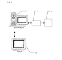
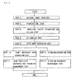
- the image processing apparatus 10 of the present example is a personal computer provided with an image processing board 11 dedicated to image processing (in the present example, made by Sharp Semiconductor Co. , GPB-K) and a large capacity hard disk 13 for image storage and mounting an external monitor 12 for image display. Further, the apparatus stores the processing routine of the flow chart shown in FIG. 2, processes the image signal of an examined joint obtained by the image-taking means, and automatically extracts the destroyed part region by a predetermined method.
- an image of the knee joint of the rat being examined is obtained by the ⁇ X-ray CT in continuous tomographs at predetermined intervals and loaded into the image processing apparatus. Note that this image should be one giving a spatial resolution of an extent (10 to 30 ⁇ m) sufficient for observing the shape of the joint surface.
- the ⁇ X-ray CT image used in the present example is a slice of 512 pixels vertically x 512 pixels horizontally x 210 in height (axial direction) (maximum 512 slices possible).
- the dimension per pixel in the cross-section is 37.5 ⁇ m, the slice distance 30 ⁇ m, and the luminance value CT of each pixel (also called the "concentration value") expressed by 2 8 gradations.
- This image is read into the image processing apparatus 10 by input of the original image at step 1 of FIG. 2.
- the digitalization step of step 2 of FIG. 2 is executed to define the joint subchondral bone (hereinafter the "joint part").
- the digitalization method uses the following judgement and analysis method.
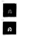
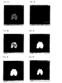
- FIG. 3A is the originally taken image of the cross-section of the rat femur distal epiphysis.
- FIG. 3B is obtained by binarizing (no object "0", object "1") the photographed image for clarifying the joint part and background part.
- the actual image data is 8-bit data. It is necessary to divide the data into the joint part data and the background data by digitalization.
- the method for determining the threshold value by the above method is called the "discrimination analysis method".
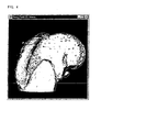
- a 3D image (FIG. 4) of the knee joint is obtained.
- the joint internal cavity (hereinafter “medullary cavity”) is extracted in advance to prepare a filled image of the joint inside structure, in other words, the sum (OR) image of the joint part and the medullary cavity part. It becomes possible to accurately analyze the structural characteristics of the joint surface by this image processing.
- the routine is to perform n number of expansion processings (FIG. 5C) on the joint part image (FIG. 5B) digitalized by the above discrimination analysis method, then detect the hole part image (FIG. 5D) other than the maximum hole part to obtain the sum (OR) image (FIG. 5E) of the hole part image (FIG. 5D) and expansion image (FIG. 5C). Next, it performs n number of image shrinkage processings (FIG. 5F). In the case of the present embodiment, n was made 10 from the interval between the divided parts.
- step for 3D labeling of step 4 of FIG. 2 will be explained.
- the 3D labeling processing is performed on the 3D image data of the joint part using the filled image of the medullary cavity (sum (OR) image of FIG. 4 and FIG. 6). It is performed as pre-treatment for extracting the analyzed joint part shown in step 5 of FIG. 2. Further, the "labeling" spoken of here judges if the objects are connected, defines the label number for the objects connected three-dimensionally, and counts the number of connections when there are objects between adjoining data designated for the 3D image data.
- the scanning method scans from the element (2,2,2) to the element (i-1, j-1, k-1).
- the label (value of image L) of Xp is abbreviated as Lp.
- FIG. 8 shows a flow chart of the algorithm.
- the variable ⁇ expressing the connection part (hereinafter referred to as " ⁇ ") is initialized to 0.
- the element for starting the scan is made ( 2 , 2 , 2).
- the current element is defined as (i, j, k) and, at step 4, the processing is branched depending on whether the input image (Fijk) is 0 or 1.
- the label image Lijk is made 0 and step 8 is executed.
- the input image (Fijk) is 1 at step 4
- P 0, 1, 2, ..., 13 ⁇ . These are made L1, L2, ..., Ln in the order of the smallest value.
- step 6 the processing is branched at step 7 corresponding to the value of n.
- n 0, the object appears for the first time, so ⁇ +1, the label table T( ⁇ ) ⁇ is inserted, the label table Lijk ⁇ is inserted, and step 8 is executed.
- step 8 if there are no longer any elements to be scanned remaining, the routine proceeds to step 9, while if there are any remaining, the routine returns to step 3. Step 3 to step 8 are repeated until there are no longer any elements to be scanned left.
- the numbers are reallocated to make them consecutive.
- the maximum value of the label numbers stored in the label table T( ⁇ ) is detected and that made the maximum label number:Lmax.
- step 13 all of the label images are scanned. If larger than 0, at step 12, by entering the consecutively numbered label table T (Lijk) for Lijk, all of the processing is completed.
- the final label image Lijk stores the 3D labeling data, while the maximum label number is stored in Lmax.
- the results of labeling near 26 using the actual rat knee joint part are shown in FIG. 9.
- an algorithm for automatically judging, identifying, and extracting the joint images to be evaluated, that is, the femur, tibia, patella, and meniscus, from the correspondence of the center of gravity positions of the knee joint.
- the method of extracting the femur, tibia, patella, and meniscus to be analyzed using the rat knee joint (FIG. 9) will be explained.
- the CT tomographic slice image taken is comprised of a group of slice images in the order from the tibia to the femur direction (smaller slice image numbers show tibia side).
- the method of extraction of the tibia part consists of approaching the first of the CT tomograph slice images and extraction using the characteristic of the greatest number of voxels.
- the number of voxels is defined as the number of voxels of each label image by counting the frequency of each label number at the label image Lijk.
- the method of extraction of the femur consists of approaching the last of the CT tomograph slice images and extraction using the characteristic of the greatest number of voxels.
- the method of extraction of the patella consists of similarly approaching the last of the CT tomograph slice images and extraction using the characteristic of the second greatest number of voxels.
- the method of extraction of the meniscus consists, as shown in FIG. 10, of calculating the center of gravity coordinates of the joint parts being analyzed and defining the group of labels present at the top half (direction of smaller numbers of CT tomographic slice image) of the region defined from the center of gravity coordinates of the patella and center of gravity coordinates of the tibia as the meniscus.
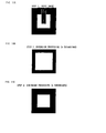
- FIG. 11 shows the principle simply in two dimensions.
- This image is made an object of white (hereinafter "1-pixels") and a background of black (hereinafter "0-pixels").
- a 2-n pixel block-shaped hole was prepared.
- the "pixel” is a unit expressing the magnitude of the image.
- the results of expansion of the image n times are shown. In this case, the image boundary also becomes larger, but the 2-n pixel hole is also filled.
- the results of shrinkage of the image n times are shown. The sizee of the image as a whole matches with the input image, but it is learned that the recessed region is filled.
- step 4 the input image (step 1) is subtracted from the shrunk image (step 3) , whereby it becomes possible to extract the image of only the recessed region.
- a characteristic of the Expansion and Shrinkage method is the advantage that it is possible to extract a recessed region of two times the number of expansions designated and the time for calculation is comparatively fast.
- An example of the extraction of the destroyed part of the femur distal epiphysis of a rat having joint destruction is shown in FIG. 12.
- FIG. 13 shows briefly the principle of this.
- an explanatory use input image is prepared. This image is made an object of white (hereinafter "1-pixels”) and a background of black (hereinafter "0-pixels"). As a recessed structure, a 2-n pixel block-shaped hole was prepared.
- a boundary pixel of the object is extracted. The method of extraction of the boundary pixel consists of judging a focused pixel to be a boundary if there is a 0-pixel at a neighboring pixel of a focused 1-pixel.
- a judgement region defining sphere (hereinafter referred to as a "sphere C1") of the radius r1 is fit over the boundary focused pixel and the volume overlapping the object is counted.
- the region (A+B+C) corresponds to this.
- a curvature defining sphere of a radius r2 (hereinafter the "sphere C2") is fit so as to cover the sphere C1 at the center and the region (a) where the sphere C1 and sphere C2 do not overlap is made the judged volume. Whether to fill the focused 1-pixels or not is judged by the following equation 4. Equation 4: Volume of region (A+B+C) > Volume of region (A)
- the focused boundary pixel that is, the 1-pixel
- the focused boundary pixel is processed to be filled. If performing this processing for the entire image until there are no longer locations to be filled, it is possible to define the filled image (131 in FIG. 13D) of step 4.
- This Sphere Scanning method is characterized by being able to tolerate gentle irregular structures of the surface of the 3D structure being evaluated and being able to selectively extract sharp changes in the surface structure.
- An example of extraction of the destroyed part of the femur distal epiphysis of a rat having joint destruction using the Sphere Fitting method by the method of scanning of the left of FIG. 7 is shown in FIG. 14.
- a “voxel” is the smallest cube of FIG. 16.
- the voxel value is the value defined on the cube.
- (a) corresponds to the joint part region data digitalized at step 2 of FIG. 2
- (b) corresponds to the medullary cavity region extracted at step 3 of FIG. 2
- (c) corresponds to the destroyed part region extracted at step 6 of FIG. 2.
- the voxel value of the joint part region is defined as "1", the voxel value of the medullary cavity region as "2", the voxel value of the destroyed part region as "3" , and the voxel value of the background region as "0".
- the Advanced Marching Cubes method is the method of defining in advance the boundary surface as shown in FIG. 18 by the 21 patterns of voxel values conceivable from the 2 x 2 x 2 patterns of eight cubes (FIG. 12) centered on a voxel and defining the boundary region by pattern matching with the actual model .
- the joint BS/BV expresses the magnitude of the surface area per unit volume and is one indicator of the complexity of the surface structure of the joint part.
- the volume (V1) and surface area (S1) show the volume and surface area before expansion, while the volume (V2) and surface area (S2) show the volume and surface area after image expansion (one voxel is a worth of expansion).
- the value found from this equation becomes positive at a projecting structural part, while becomes negative at a recessed surface part. Therefore, as an overall structure, the value becomes positive for a structure comprised mostly of projecting structures, while the value becomes negative for a structure comprised mostly of recessed structures. When the numbers of projecting structures and recessed structures are substantially equal, the value becomes close to zero.
- the destroyed part volume and destroyed part surface area of the parameter 5 and parameter 6 of FIG. 15 will be explained.
- the method of defining the boundary surface of the object (Advanced Marching Cubes method: Japanese Patent No. 02798561) is used and an image processing means defining the image to give continuous triangles at the boundary surface is used to find the destroyed part volume and destroyed part surface area.
- the destroyed part surface area expresses the surface area of the part where the joint region (a) and destroyed region (c) overlap.
- the destroyed part inside surface area in other words, means the surface area of the destroyed part at the joint surface and is an important indicator in judging the extent of the joint destruction.
- the method of finding the parameter 8 of FIG. 15, that is, the number of destroyed parts will be explained.
- the number of the independent entities on the image are found. This number corresponds to the number of the destroyed parts.
- the destroyed part BS/BV expresses the amount of the surface area per unit volume and is one indicator expressing the complexity of the destroyed part structure.
- the JS region is a space between a pair of joint bones.
- 3D image data of the JS region can be extracted by applying the Expansion and Shrinkage method and Sphere Scanning method to the joint bones to be analyzed for the JS region.
- all independent joint parts present in the examined joint region are assigned independent label numbers in the present invention. Due to this, it is possible to designate two 3D structures having any label numbers, in other words, any pair of joint bones, for analysis. Further, similarly, in the present invention, when analyzing the knee joint, it is possible to automatically discriminate and assign label numbers to the joint images to be evaluated, that is, the femur, tibia, patella, and meniscus, from the correspondence of the center of gravity positions of the knee joint. Due to this, it is possible to automatically designate a pair of joint bones of the knee, that is, the femur and tibia, for analysis.
- FIG. 20 A flow chart of the method of definition of the JS region is shown in FIG. 20. The specific steps will be explained taking as an example a model of the rat knee joint, that is, the femur and tibia.
- a composite image (image 1) of the two joint bones to be analyzed is created.
- the Expansion and Shrinkage method (or Sphere Scanning method) is executed in the same way as the joint destroyed part region for the image 1 at step 2 of FIG. 20 to prepare a differential image from the image 1 (image 2: 213 of FIG. 21A).
- the Expansion and Shrinkage method is executed for the image of only the femur at step 3 of FIG. 20 to extract the joint destroyed part region of the femur and create the image 3 (214 of FIG. 21B).
- the Expansion and Shrinkage method is executed for the image of only the tibia at step 4 of FIG.
- the JSV is the volume of the JS region.
- the Advanced Marching Cubes method is applied. Specifically, by defining the cubes sampled by 2 x 2 x 2 voxel regions and the boundary surface by pattern matching on the cubes of FIG. 18 for the JS region (i) and other regions (e), (f), (g), (h), and (j) and counting the cube data and boundary surface data, JSV can be measured.
- the JSMD is the shortest length of the distance between a pair of joint bones, in this example, the shortest distance between the femur distal epiphysis and the tibia proximal epiphysis.
- a flow chart of the method of calculation of the JSMD is shown in FIG. 23.
- the voxel list (241) of the femur side and the voxel list (242) of the tibia side contacting the JS region could be extracted.
- the distance data from the voxel coordinate list (241) of the femur side to the voxel coordinate list (242) of the tibia side is found and the shortest distance is made the JSMD.
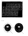
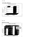
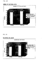
- FIG. 25 shows the results of analysis of the parameters relating to the destroyed part shown in FIG. 15 for the femur joint part of a normal rat (hereinafter referred to as "normal”) and the femur joint part of a rat having joint destruction (hereinafter referred to as “diseased").
- the increase in the joint BS/BV in the diseased state means an increase in the complexity of the surface structure
- a decrease in the irregularity of the joint surface means an increase in the surface recessed structures.
- Changes in any parameter mean an increase in the destruction of the joint in the diseased state.
- changes in shape of the joint surface can be specifically extracted for the first time.
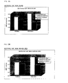
- the results of measurement of the irregularity of the joint surface without performing processing for filling the inside of the joint are shown in FIG. 26 as a comparative example. Unlike the case of performing the filling processing (FIG.
- the normal state gives lower values than the diseased state and the normal state gives more surface recessed structures than the diseased state. This is because in the normal state compared with the diseased state, there are more structures inside the joint, that is, trabeculars, and more complicated structures are formed. From these facts, according to the present invention, it can be said that the sensitivity of detection of structural changes of the joint structure is strikingly improved.
- the Sphere Scanning method enables lower values to be obtained (FIG. 25E to FIG. 25M) . This is due to the characteristics of the two types of extraction methods .
- the Expansion and Shrinkage method accurately extracts even fine changes in the surface structure, while the Sphere Scanning method tolerates gentle irregularity of the surface.
- FIG. 27 shows the JS region extracted by the Expansion and Shrinkage method for the normal and diseased states.
- the JS region is accurately extracted by itself.
- the present invention it is shown that three-dimensional visualization and extraction of the JS region, which have been difficult up until now, are possible.
- the JS region can be similarly extracted even by the Sphere Scanning method.
- FIG. 28 shows the results of measurement of the JSMD for normal and diseased JS regions shown in FIG. 27.
- a reduction in the JSMD was observed.
- the present invention it has become possible to extract the structure of the joint surface with good sensitivity by processing for filling the joint inside structure and to extract the recessed structure region from the joint, that is, the destroyed part, at a high speed, simply, with a good repeatability by the development of two types of image processing methods. Further, the image data of the joint surface and destroyed part obtained can provide structural indicators relating to joint destruction by 3D structural analysis. Further, by analyzing the pair of joint bones forming a joint, it has become possible to analyze the 3D structure of a JS region at a high speed with a good repeatability.
- the joint part and joint destroyed part defined in the present invention can be displayed using a visualization tool and becomes possible to visually provide to an observer 3D spatial-like information for the joint surface structure and the joint destroyed part of the joint.
- the analysis of the 3D joint structure according to the present invention can be applied to not only the knee joint, but also other joint.
- the present invention can be expected to be allow all of the diagnostic image information obtained from a ⁇ X-ray CT apparatus or other clinical CT apparatus, pQCT photographic apparatus, MRI, etc. to be applied to measurement of the 3D structure of a joint.
Landscapes
- Engineering & Computer Science (AREA)
- Health & Medical Sciences (AREA)
- Medical Informatics (AREA)
- Life Sciences & Earth Sciences (AREA)
- Physics & Mathematics (AREA)
- General Health & Medical Sciences (AREA)
- Nuclear Medicine, Radiotherapy & Molecular Imaging (AREA)
- Radiology & Medical Imaging (AREA)
- High Energy & Nuclear Physics (AREA)
- Molecular Biology (AREA)
- Theoretical Computer Science (AREA)
- Orthopedic Medicine & Surgery (AREA)
- Dentistry (AREA)
- Oral & Maxillofacial Surgery (AREA)
- Computer Vision & Pattern Recognition (AREA)
- Biophysics (AREA)
- Quality & Reliability (AREA)
- Optics & Photonics (AREA)
- Pathology (AREA)
- Biomedical Technology (AREA)
- Heart & Thoracic Surgery (AREA)
- General Physics & Mathematics (AREA)
- Surgery (AREA)
- Animal Behavior & Ethology (AREA)
- Public Health (AREA)
- Veterinary Medicine (AREA)
- Apparatus For Radiation Diagnosis (AREA)
- Image Analysis (AREA)
- Image Processing (AREA)
- Processing Or Creating Images (AREA)
- Magnetic Resonance Imaging Apparatus (AREA)
- Measuring And Recording Apparatus For Diagnosis (AREA)
- Measurement Of The Respiration, Hearing Ability, Form, And Blood Characteristics Of Living Organisms (AREA)
- Length Measuring Devices By Optical Means (AREA)
Abstract
Description
δB2: Interclass variance
δW2: Intraclass variance
ω2: Number of pixels of class 2
M1: Mean luminance value of pixels of class 1
M2: Mean luminance value of pixels of class 2
δ2: Variance of luminance values of pixels of class 2
V1: Volume before 3D image expansion
S2: Surface area after 3D image expansion
V2: Volume after 3D image expansion
BV: Volume of destroyed part
Claims (22)
- An image processing method having the step of filling in a medullary cavity region comprising a hollow region inside a joint of a digitalized image of the cross-section of an examined joint using the Expansion and Shrinkage method and extracting the contour of the tomographic image of the joint.
- A 3D image processing method comprising performing 3D labeling by a 3D image obtained by stacking digitalized images of cross-sections of the examined joint generated by the image processing method of claim 1 or digitalized images of cross-sections of the examined joint not pre-processed and defining the joint image to be evaluated.
- An image processing method for judging, identifying, and extracting a joint image to be evaluated from correspondence of center of gravity positions of joint bones using a 3D label image of joint parts prepared by the image processing method of claim 2.
- An image processing method for judging, identifying, and extracting a joint image of a femur, tibia, patella, and/or meniscus to be evaluated from a relative relationship of center of gravity positions of joint bones using a 3D label image of joint parts prepared by the image processing method of claim 2.
- An image processing method having the step of extracting a 3D image of a joint destroyed part using the 3D image expansion method and 3D image shrinkage method for a 3D bone image of a joint defined by the image processing method of claim 2.
- An image processing method having the step of extracting a 3D image of a joint destroyed part using the 3D Sphere Scanning method for a 3D bone image of a joint defined by the image processing method of claim 2.
- An image processing method having the step of extracting a 3D image of a joint destroyed part using the 3D image expansion method and 3D image shrinkage method for a 3D bone image of a joint defined by the image processing method of claim 3.
- An image processing method having the step of extracting a 3D image of a joint destroyed part using the 3D Sphere Scanning method for a 3D bone image of a joint defined by the image processing method of claim 3.
- An image processing method having the step of extracting a 3D image of a joint destroyed part using the 3D image expansion method and 3D image shrinkage method for a 3D bone image of a joint defined by the image processing method of claim 4.
- An image processing method having the step of extracting a 3D image of a joint destroyed part using the 3D Sphere Scanning method for a 3D bone image of a joint defined by the image processing method of claim 4.
- A joint structure evaluation method characterized by measuring surface irregularity for a 3D image of a joint bone produced by the image processing method of claim 2.
- A joint structure evaluation method characterized by measuring structural parameters of volume (BV) , surface area (BS), BS/BV, the number, average volume (volume/number), and/or mean surface area (surface area/number) for a 3D structure produced by the image processing method of claims 1 to 10.
- An image processing method having the step of extracting a 3D image of joint space region using the 3D image expansion method and 3D image shrinkage method for any two analysis objects in a 3D bone image of a joint defined by the image processing method of claim 2.
- An image processing method having the step of extracting a 3D image of joint space using the 3D Sphere Scanning method for any two analysis objects in a 3D bone image of a joint defined by the image processing method of claim 2.
- An image processing method having the step of extracting a 3D image of joint space using the 3D image expansion method and 3D image shrinkage method for any two analysis objects in a 3D bone image of a joint defined by the image processing method of claim 3.
- An image processing method having the step of extracting a 3D image of joint space using the 3D Sphere Scanning method for any two analysis objects in a 3D bone image of a joint defined by the image processing method of claim 3.
- An image processing method having the step of extracting a 3D image of joint space using the 3D image expansion method and 3D image shrinkage method for any two analysis objects in a 3D bone image of a joint defined by the image processing method of claim 4.
- An image processing method having the step of extracting a 3D image of joint space using the 3D Sphere Scanning method for any two analysis objects in a 3D bone image of a joint defined by the image processing method of claim 4.
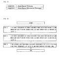
- A joint structure evaluation method characterized by measuring structural parameters of the Joint Space Volume (JSV) and Joint Space Minimum Distance (JSMD) for a 3D structure produced by the image processing methods of claims 13 to 18.
- An evaluation method for evaluating the structure of a joint in an animal model of a joint related ailment using the method of any one of claims 1 to 19.
- An evaluation method for evaluating the structure of a joint of a patient of a joint related ailment using the method of any one of claims 1 to 19.
- A diagnosis method for diagnosing joint destruction of a patient of a joint related ailment using the method of any one of claims 1 to 19.
Applications Claiming Priority (3)
| Application Number | Priority Date | Filing Date | Title |
|---|---|---|---|
| JP2001129220 | 2001-04-26 | ||
| JP2001129220 | 2001-04-26 | ||
| PCT/JP2002/004256 WO2002087444A1 (en) | 2001-04-26 | 2002-04-26 | Three-dimensional joint structure measuring method |
Publications (3)
| Publication Number | Publication Date |
|---|---|
| EP1382297A1 true EP1382297A1 (en) | 2004-01-21 |
| EP1382297A4 EP1382297A4 (en) | 2008-01-23 |
| EP1382297B1 EP1382297B1 (en) | 2012-01-04 |
Family
ID=18977778
Family Applications (1)
| Application Number | Title | Priority Date | Filing Date |
|---|---|---|---|
| EP02720630A Expired - Lifetime EP1382297B1 (en) | 2001-04-26 | 2002-04-26 | Three-dimensional joint structure measuring method |
Country Status (6)
| Country | Link |
|---|---|
| US (1) | US7664297B2 (en) |
| EP (1) | EP1382297B1 (en) |
| JP (1) | JP3888975B2 (en) |
| AU (1) | AU2002251559B9 (en) |
| CA (1) | CA2427695C (en) |
| WO (1) | WO2002087444A1 (en) |
Cited By (4)
| Publication number | Priority date | Publication date | Assignee | Title |
|---|---|---|---|---|
| CN110251047A (en) * | 2014-03-28 | 2019-09-20 | 直观外科手术操作公司 | The quantitative three-dimensional imaging and printing of surgery implant |
| US10621726B2 (en) | 2015-03-19 | 2020-04-14 | Nobel Biocare Services Ag | Segmentation of objects in image data using channel detection |
| US11266465B2 (en) | 2014-03-28 | 2022-03-08 | Intuitive Surgical Operations, Inc. | Quantitative three-dimensional visualization of instruments in a field of view |
| US11304771B2 (en) | 2014-03-28 | 2022-04-19 | Intuitive Surgical Operations, Inc. | Surgical system with haptic feedback based upon quantitative three-dimensional imaging |
Families Citing this family (36)
| Publication number | Priority date | Publication date | Assignee | Title |
|---|---|---|---|---|
| US8545569B2 (en) | 2001-05-25 | 2013-10-01 | Conformis, Inc. | Patient selectable knee arthroplasty devices |
| US8556983B2 (en) | 2001-05-25 | 2013-10-15 | Conformis, Inc. | Patient-adapted and improved orthopedic implants, designs and related tools |
| US8882847B2 (en) * | 2001-05-25 | 2014-11-11 | Conformis, Inc. | Patient selectable knee joint arthroplasty devices |
| US8480754B2 (en) | 2001-05-25 | 2013-07-09 | Conformis, Inc. | Patient-adapted and improved articular implants, designs and related guide tools |
| EP1322224B1 (en) | 2000-09-14 | 2008-11-05 | The Board Of Trustees Of The Leland Stanford Junior University | Assessing condition of a joint and cartilage loss |
| JP2003141548A (en) | 2001-10-22 | 2003-05-16 | Ge Medical Systems Global Technology Co Llc | Three-dimensional labeling apparatus and method |
| JP5079008B2 (en) * | 2006-09-19 | 2012-11-21 | シナーク・インコーポレイテッド | Lesion display measure related to cartilage structure and its automatic quantification |
| JP4934786B2 (en) * | 2006-10-13 | 2012-05-16 | 国立大学法人 東京大学 | Knee joint diagnosis support method, apparatus and program |
| US7778453B2 (en) * | 2007-01-30 | 2010-08-17 | Siemens Aktiengesellschaft | Multi-modality method and software for representation and evaluation of extremity exposures of arthritis/arthrosis patients |
| US8311306B2 (en) * | 2008-04-30 | 2012-11-13 | Otismed Corporation | System and method for image segmentation in generating computer models of a joint to undergo arthroplasty |
| JP2011519713A (en) | 2008-05-12 | 2011-07-14 | コンフォーミス・インコーポレイテッド | Devices and methods for treatment of facet joints and other joints |
| EP2405865B1 (en) | 2009-02-24 | 2019-04-17 | ConforMIS, Inc. | Automated systems for manufacturing patient-specific orthopedic implants and instrumentation |
| EP2509539B1 (en) | 2009-12-11 | 2020-07-01 | ConforMIS, Inc. | Patient-specific and patient-engineered orthopedic implants |
| US8942917B2 (en) | 2011-02-14 | 2015-01-27 | Microsoft Corporation | Change invariant scene recognition by an agent |
| EP2754419B1 (en) | 2011-02-15 | 2024-02-07 | ConforMIS, Inc. | Patient-adapted and improved orthopedic implants |
| US8571263B2 (en) * | 2011-03-17 | 2013-10-29 | Microsoft Corporation | Predicting joint positions |
| US9495752B2 (en) * | 2012-09-27 | 2016-11-15 | Siemens Product Lifecycle Management Software Inc. | Multi-bone segmentation for 3D computed tomography |
| US9857470B2 (en) | 2012-12-28 | 2018-01-02 | Microsoft Technology Licensing, Llc | Using photometric stereo for 3D environment modeling |
| US9940553B2 (en) | 2013-02-22 | 2018-04-10 | Microsoft Technology Licensing, Llc | Camera/object pose from predicted coordinates |
| KR101502708B1 (en) * | 2013-12-31 | 2015-03-13 | 가톨릭대학교 산학협력단 | Sex determination using discriminant analysis of the volume and surface area of lower/upper extremity bones |
| US20160180520A1 (en) * | 2014-12-17 | 2016-06-23 | Carestream Health, Inc. | Quantitative method for 3-d joint characterization |
| JP6599672B2 (en) * | 2015-07-17 | 2019-10-30 | 日本電産サンキョー株式会社 | Character cutout device, character recognition device, and character cutout method |
| US11526988B2 (en) | 2015-12-18 | 2022-12-13 | Episurf Ip-Management Ab | System and method for creating a decision support material indicating damage to an anatomical joint |
| DK3181050T3 (en) * | 2015-12-18 | 2020-05-11 | Episurf Ip Man Ab | System and method for forming a decision support material indicating damage to an anatomical joint |
| US10299750B2 (en) | 2016-08-05 | 2019-05-28 | Toshiba Medical Systems Corporation | Medical image processing apparatus and X-ray CT apparatus |
| EP3513770A4 (en) | 2016-09-14 | 2020-09-23 | Cyberdyne Inc. | DEVICE FOR MANUFACTURING AN INSTRUMENT FOR KNEE CORRECTION, METHOD FOR MANUFACTURING INSTRUMENT FOR KNEE CORRECTION, DEVICE FOR ASSISTING THE TREATMENT OF A KNEE JOINT, AND METHOD FOR SUPPORTING THE KNEE |
| JP6659501B2 (en) * | 2016-09-14 | 2020-03-04 | 富士フイルム株式会社 | Cartilage quantification device, method and program |
| US11250561B2 (en) | 2017-06-16 | 2022-02-15 | Episurf Ip-Management Ab | Determination and visualization of damage to an anatomical joint |
| US10783718B2 (en) | 2018-10-09 | 2020-09-22 | Microsoft Technology Licensing, Llc | Complexity reduction of objects via hole filling |
| US10438420B1 (en) | 2018-10-09 | 2019-10-08 | Microsoft Technology Licensing, Llc | Complexity reduction of objects via cavity removal |
| USD908733S1 (en) | 2018-10-15 | 2021-01-26 | Episurf Ip Management Ab | Display screen with epioscopy icon |
| US11645749B2 (en) | 2018-12-14 | 2023-05-09 | Episurf Ip-Management Ab | Determination and visualization of damage to an anatomical joint |
| US20220383652A1 (en) * | 2019-11-07 | 2022-12-01 | Google Llc | Monitoring Animal Pose Dynamics from Monocular Images |
| CN111415356B (en) * | 2020-03-17 | 2020-12-29 | 推想医疗科技股份有限公司 | Segmentation method, device, medium and electronic device for signs of pneumonia |
| US11621086B2 (en) | 2020-06-04 | 2023-04-04 | Episurf Ip-Management Ab | Customization of individualized implant |
| JP7472845B2 (en) * | 2020-07-21 | 2024-04-23 | 株式会社島津製作所 | X-ray imaging device and image processing method |
Family Cites Families (20)
| Publication number | Priority date | Publication date | Assignee | Title |
|---|---|---|---|---|
| JPS5846945A (en) * | 1981-09-14 | 1983-03-18 | 川井 忠彦 | Method and apparatus for diagnosis of dislocation of crotch joint |
| US5247934A (en) * | 1991-08-09 | 1993-09-28 | Trustees Of The University Of Pennsylvania | Method and apparatus for diagnosing osteoporosis with MR imaging |
| JP2798561B2 (en) | 1992-07-16 | 1998-09-17 | 帝人株式会社 | Object boundary surface generation method |
| CA2201057C (en) * | 1996-03-29 | 2002-01-01 | Kenji Morimoto | A method of processing a sectional image of a sample bone including a cortical bone portion and a cancellous bone portion |
| JPH09322883A (en) | 1996-06-05 | 1997-12-16 | Tadahiko Kawai | Analyzer of contact pressure distribution at jaw joint |
| US6021213A (en) * | 1996-06-13 | 2000-02-01 | Eli Lilly And Company | Automatic contextual segmentation for imaging bones for osteoporosis therapies |
| US5820559A (en) * | 1997-03-20 | 1998-10-13 | Ng; Wan Sing | Computerized boundary estimation in medical images |
| JP3656695B2 (en) | 1997-09-30 | 2005-06-08 | 富士写真フイルム株式会社 | Bone measuring method and apparatus |
| JPH11296700A (en) * | 1998-04-07 | 1999-10-29 | Toshiba Fa Syst Eng Corp | Three-dimensional image display device |
| US6442287B1 (en) * | 1998-08-28 | 2002-08-27 | Arch Development Corporation | Method and system for the computerized analysis of bone mass and structure |
| US7239908B1 (en) * | 1998-09-14 | 2007-07-03 | The Board Of Trustees Of The Leland Stanford Junior University | Assessing the condition of a joint and devising treatment |
| JP2000126178A (en) * | 1998-10-27 | 2000-05-09 | Mitani Sangyo Co Ltd | Three-dimensional surface shape quantification method and automatic malignant tumor identification method using the same |
| JP3049021B2 (en) | 1998-11-05 | 2000-06-05 | 五大株式会社 | Image processing apparatus, image processing method, and recording medium recording image processing program |
| JP2000180377A (en) | 1998-12-21 | 2000-06-30 | Sharp Corp | Defect / foreign matter inspection equipment |
| WO2000074567A1 (en) * | 1999-06-03 | 2000-12-14 | Teijin Limited | Bone measuring method |
| DE60136549D1 (en) * | 2000-09-14 | 2008-12-24 | Univ R | METHOD FOR MANIPULATING MEDICAL IMAGES |
| EP1322224B1 (en) * | 2000-09-14 | 2008-11-05 | The Board Of Trustees Of The Leland Stanford Junior University | Assessing condition of a joint and cartilage loss |
| US7660453B2 (en) * | 2000-10-11 | 2010-02-09 | Imaging Therapeutics, Inc. | Methods and devices for analysis of x-ray images |
| US6785409B1 (en) * | 2000-10-24 | 2004-08-31 | Koninklijke Philips Electronics, N.V. | Segmentation method and apparatus for medical images using diffusion propagation, pixel classification, and mathematical morphology |
| US7133543B2 (en) * | 2001-06-12 | 2006-11-07 | Applied Imaging Corporation | Automated scanning method for pathology samples |
-
2002
- 2002-04-26 CA CA2427695A patent/CA2427695C/en not_active Expired - Fee Related
- 2002-04-26 WO PCT/JP2002/004256 patent/WO2002087444A1/en not_active Ceased
- 2002-04-26 US US10/475,694 patent/US7664297B2/en not_active Expired - Fee Related
- 2002-04-26 AU AU2002251559A patent/AU2002251559B9/en not_active Ceased
- 2002-04-26 EP EP02720630A patent/EP1382297B1/en not_active Expired - Lifetime
- 2002-04-26 JP JP2002584799A patent/JP3888975B2/en not_active Expired - Fee Related
Cited By (6)
| Publication number | Priority date | Publication date | Assignee | Title |
|---|---|---|---|---|
| CN110251047A (en) * | 2014-03-28 | 2019-09-20 | 直观外科手术操作公司 | The quantitative three-dimensional imaging and printing of surgery implant |
| CN110251047B (en) * | 2014-03-28 | 2022-01-18 | 直观外科手术操作公司 | Quantitative three-dimensional imaging and printing of surgical implants |
| US11266465B2 (en) | 2014-03-28 | 2022-03-08 | Intuitive Surgical Operations, Inc. | Quantitative three-dimensional visualization of instruments in a field of view |
| US11304771B2 (en) | 2014-03-28 | 2022-04-19 | Intuitive Surgical Operations, Inc. | Surgical system with haptic feedback based upon quantitative three-dimensional imaging |
| US12262951B2 (en) | 2014-03-28 | 2025-04-01 | Intuitive Surgical Operations, Inc. | Quantitative three-dimensional visualization of instruments in a field of view |
| US10621726B2 (en) | 2015-03-19 | 2020-04-14 | Nobel Biocare Services Ag | Segmentation of objects in image data using channel detection |
Also Published As
| Publication number | Publication date |
|---|---|
| US7664297B2 (en) | 2010-02-16 |
| CA2427695A1 (en) | 2003-05-01 |
| EP1382297A4 (en) | 2008-01-23 |
| AU2002251559B2 (en) | 2006-05-18 |
| AU2002251559B9 (en) | 2006-06-29 |
| WO2002087444A1 (en) | 2002-11-07 |
| CA2427695C (en) | 2012-12-11 |
| JP3888975B2 (en) | 2007-03-07 |
| JPWO2002087444A1 (en) | 2004-08-12 |
| US20040136583A1 (en) | 2004-07-15 |
| EP1382297B1 (en) | 2012-01-04 |
Similar Documents
| Publication | Publication Date | Title |
|---|---|---|
| US7664297B2 (en) | Three-dimensional joint structure measuring method | |
| US6799066B2 (en) | Technique for manipulating medical images | |
| Duryea et al. | Digital tomosynthesis of hand joints for arthritis assessment | |
| US20040147830A1 (en) | Method and system for use of biomarkers in diagnostic imaging | |
| JP5192921B2 (en) | Ultrasonic diagnostic equipment | |
| JP4495891B2 (en) | Bone measurement method | |
| JP3499761B2 (en) | Bone image processing method and bone strength evaluation method | |
| US20040066955A1 (en) | Method and system for assessment of biomarkers by measurement of response to stimulus | |
| EP1361820B1 (en) | Method for the non-invasive imaging of anatomic tissue structures | |
| US20030036083A1 (en) | System and method for quantifying tissue structures and their change over time | |
| JP5235103B2 (en) | Ultrasonic diagnostic equipment | |
| JPWO2000074567A1 (en) | Bone measurement method | |
| JP5302578B2 (en) | Ultrasonic diagnostic equipment | |
| US20230289967A1 (en) | Device for diagnosing spine conditions | |
| US20050113663A1 (en) | Method and system for automatic extraction of load-bearing regions of the cartilage and measurement of biomarkers | |
| JP2000126178A (en) | Three-dimensional surface shape quantification method and automatic malignant tumor identification method using the same | |
| US20250173869A1 (en) | Method for aiding the diagnose of spine conditions | |
| US20060247864A1 (en) | Method and system for assessment of biomarkers by measurement of response to surgical implant | |
| Ikuta et al. | Quantitative analysis using the star volume method applied to skeleton patterns extracted with a morphological filter | |
| Sevestre-Ghalila et al. | Texture image analysis for osteoporosis detection with morphological tools | |
| JP2011125757A (en) | Ultrasonic image data processor | |
| JPH09271470A (en) | Bone measurement method | |
| Jung et al. | A Method for Selecting Optimal MRI Sequence for Automatic Segmentation Based on Edge Analysis | |
| KR20230039084A (en) | Method for evaluating low limb alignment and device for evaluating low limb alignment using the same |
Legal Events
| Date | Code | Title | Description |
|---|---|---|---|
| PUAI | Public reference made under article 153(3) epc to a published international application that has entered the european phase |
Free format text: ORIGINAL CODE: 0009012 |
|
| 17P | Request for examination filed |
Effective date: 20030520 |
|
| AK | Designated contracting states |
Kind code of ref document: A1 Designated state(s): AT BE CH CY DE DK ES FI FR GB GR IE IT LI LU MC NL PT SE TR |
|
| AX | Request for extension of the european patent |
Extension state: AL LT LV MK RO SI |
|
| A4 | Supplementary search report drawn up and despatched |
Effective date: 20071228 |
|
| RIC1 | Information provided on ipc code assigned before grant |
Ipc: G06T 7/00 20060101AFI20071219BHEP Ipc: A61B 6/03 20060101ALI20071219BHEP |
|
| 17Q | First examination report despatched |
Effective date: 20090311 |
|
| GRAP | Despatch of communication of intention to grant a patent |
Free format text: ORIGINAL CODE: EPIDOSNIGR1 |
|
| RBV | Designated contracting states (corrected) |
Designated state(s): DE FR GB |
|
| GRAS | Grant fee paid |
Free format text: ORIGINAL CODE: EPIDOSNIGR3 |
|
| GRAA | (expected) grant |
Free format text: ORIGINAL CODE: 0009210 |
|
| AK | Designated contracting states |
Kind code of ref document: B1 Designated state(s): DE FR GB |
|
| REG | Reference to a national code |
Ref country code: GB Ref legal event code: FG4D |
|
| REG | Reference to a national code |
Ref country code: DE Ref legal event code: R096 Ref document number: 60241891 Country of ref document: DE Effective date: 20120308 |
|
| PLBE | No opposition filed within time limit |
Free format text: ORIGINAL CODE: 0009261 |
|
| STAA | Information on the status of an ep patent application or granted ep patent |
Free format text: STATUS: NO OPPOSITION FILED WITHIN TIME LIMIT |
|
| 26N | No opposition filed |
Effective date: 20121005 |
|
| REG | Reference to a national code |
Ref country code: DE Ref legal event code: R097 Ref document number: 60241891 Country of ref document: DE Effective date: 20121005 |
|
| REG | Reference to a national code |
Ref country code: FR Ref legal event code: PLFP Year of fee payment: 15 |
|
| PGFP | Annual fee paid to national office [announced via postgrant information from national office to epo] |
Ref country code: GB Payment date: 20160421 Year of fee payment: 15 Ref country code: DE Payment date: 20160426 Year of fee payment: 15 |
|
| PGFP | Annual fee paid to national office [announced via postgrant information from national office to epo] |
Ref country code: FR Payment date: 20160426 Year of fee payment: 15 |
|
| REG | Reference to a national code |
Ref country code: DE Ref legal event code: R119 Ref document number: 60241891 Country of ref document: DE |
|
| GBPC | Gb: european patent ceased through non-payment of renewal fee |
Effective date: 20170426 |
|
| REG | Reference to a national code |
Ref country code: FR Ref legal event code: ST Effective date: 20171229 |
|
| PG25 | Lapsed in a contracting state [announced via postgrant information from national office to epo] |
Ref country code: DE Free format text: LAPSE BECAUSE OF NON-PAYMENT OF DUE FEES Effective date: 20171103 Ref country code: FR Free format text: LAPSE BECAUSE OF NON-PAYMENT OF DUE FEES Effective date: 20170502 |
|
| PG25 | Lapsed in a contracting state [announced via postgrant information from national office to epo] |
Ref country code: GB Free format text: LAPSE BECAUSE OF NON-PAYMENT OF DUE FEES Effective date: 20170426 |