EP1381351B1 - Method for the continuous production of medicaments for inhalation - Google Patents
Method for the continuous production of medicaments for inhalation Download PDFInfo
- Publication number
- EP1381351B1 EP1381351B1 EP02722039A EP02722039A EP1381351B1 EP 1381351 B1 EP1381351 B1 EP 1381351B1 EP 02722039 A EP02722039 A EP 02722039A EP 02722039 A EP02722039 A EP 02722039A EP 1381351 B1 EP1381351 B1 EP 1381351B1
- Authority
- EP
- European Patent Office
- Prior art keywords
- solution
- process according
- transport medium
- medicament
- temperature
- Prior art date
- Legal status (The legal status is an assumption and is not a legal conclusion. Google has not performed a legal analysis and makes no representation as to the accuracy of the status listed.)
- Expired - Lifetime
Links
Images
Classifications
-
- A—HUMAN NECESSITIES
- A61—MEDICAL OR VETERINARY SCIENCE; HYGIENE
- A61K—PREPARATIONS FOR MEDICAL, DENTAL OR TOILETRY PURPOSES
- A61K9/00—Medicinal preparations characterised by special physical form
- A61K9/0012—Galenical forms characterised by the site of application
- A61K9/007—Pulmonary tract; Aromatherapy
- A61K9/0073—Sprays or powders for inhalation; Aerolised or nebulised preparations generated by other means than thermal energy
-
- B—PERFORMING OPERATIONS; TRANSPORTING
- B01—PHYSICAL OR CHEMICAL PROCESSES OR APPARATUS IN GENERAL
- B01F—MIXING, e.g. DISSOLVING, EMULSIFYING OR DISPERSING
- B01F33/00—Other mixers; Mixing plants; Combinations of mixers
- B01F33/30—Micromixers
- B01F33/302—Micromixers the materials to be mixed flowing in the form of droplets
- B01F33/3021—Micromixers the materials to be mixed flowing in the form of droplets the components to be mixed being combined in a single independent droplet, e.g. these droplets being divided by a non-miscible fluid or consisting of independent droplets
-
- A—HUMAN NECESSITIES
- A61—MEDICAL OR VETERINARY SCIENCE; HYGIENE
- A61K—PREPARATIONS FOR MEDICAL, DENTAL OR TOILETRY PURPOSES
- A61K9/00—Medicinal preparations characterised by special physical form
- A61K9/0012—Galenical forms characterised by the site of application
- A61K9/007—Pulmonary tract; Aromatherapy
- A61K9/0073—Sprays or powders for inhalation; Aerolised or nebulised preparations generated by other means than thermal energy
- A61K9/0075—Sprays or powders for inhalation; Aerolised or nebulised preparations generated by other means than thermal energy for inhalation via a dry powder inhaler [DPI], e.g. comprising micronized drug mixed with lactose carrier particles
-
- A—HUMAN NECESSITIES
- A61—MEDICAL OR VETERINARY SCIENCE; HYGIENE
- A61K—PREPARATIONS FOR MEDICAL, DENTAL OR TOILETRY PURPOSES
- A61K9/00—Medicinal preparations characterised by special physical form
- A61K9/14—Particulate form, e.g. powders, Processes for size reducing of pure drugs or the resulting products, Pure drug nanoparticles
- A61K9/16—Agglomerates; Granulates; Microbeadlets ; Microspheres; Pellets; Solid products obtained by spray drying, spray freeze drying, spray congealing,(multiple) emulsion solvent evaporation or extraction
- A61K9/1682—Processes
- A61K9/1688—Processes resulting in pure drug agglomerate optionally containing up to 5% of excipient
-
- B—PERFORMING OPERATIONS; TRANSPORTING
- B01—PHYSICAL OR CHEMICAL PROCESSES OR APPARATUS IN GENERAL
- B01D—SEPARATION
- B01D9/00—Crystallisation
- B01D9/0004—Crystallisation cooling by heat exchange
- B01D9/0013—Crystallisation cooling by heat exchange by indirect heat exchange
-
- B—PERFORMING OPERATIONS; TRANSPORTING
- B01—PHYSICAL OR CHEMICAL PROCESSES OR APPARATUS IN GENERAL
- B01D—SEPARATION
- B01D9/00—Crystallisation
- B01D9/0036—Crystallisation on to a bed of product crystals; Seeding
-
- B—PERFORMING OPERATIONS; TRANSPORTING
- B01—PHYSICAL OR CHEMICAL PROCESSES OR APPARATUS IN GENERAL
- B01D—SEPARATION
- B01D9/00—Crystallisation
- B01D9/0063—Control or regulation
-
- B—PERFORMING OPERATIONS; TRANSPORTING
- B01—PHYSICAL OR CHEMICAL PROCESSES OR APPARATUS IN GENERAL
- B01F—MIXING, e.g. DISSOLVING, EMULSIFYING OR DISPERSING
- B01F25/00—Flow mixers; Mixers for falling materials, e.g. solid particles
- B01F25/30—Injector mixers
- B01F25/31—Injector mixers in conduits or tubes through which the main component flows
- B01F25/313—Injector mixers in conduits or tubes through which the main component flows wherein additional components are introduced in the centre of the conduit
- B01F25/3132—Injector mixers in conduits or tubes through which the main component flows wherein additional components are introduced in the centre of the conduit by using two or more injector devices
- B01F25/31324—Injector mixers in conduits or tubes through which the main component flows wherein additional components are introduced in the centre of the conduit by using two or more injector devices arranged concentrically
-
- B—PERFORMING OPERATIONS; TRANSPORTING
- B01—PHYSICAL OR CHEMICAL PROCESSES OR APPARATUS IN GENERAL
- B01F—MIXING, e.g. DISSOLVING, EMULSIFYING OR DISPERSING
- B01F33/00—Other mixers; Mixing plants; Combinations of mixers
- B01F33/30—Micromixers
- B01F33/301—Micromixers using specific means for arranging the streams to be mixed, e.g. channel geometries or dispositions
- B01F33/3012—Interdigital streams, e.g. lamellae
-
- B—PERFORMING OPERATIONS; TRANSPORTING
- B01—PHYSICAL OR CHEMICAL PROCESSES OR APPARATUS IN GENERAL
- B01J—CHEMICAL OR PHYSICAL PROCESSES, e.g. CATALYSIS OR COLLOID CHEMISTRY; THEIR RELEVANT APPARATUS
- B01J19/00—Chemical, physical or physico-chemical processes in general; Their relevant apparatus
- B01J19/0093—Microreactors, e.g. miniaturised or microfabricated reactors
-
- B—PERFORMING OPERATIONS; TRANSPORTING
- B01—PHYSICAL OR CHEMICAL PROCESSES OR APPARATUS IN GENERAL
- B01F—MIXING, e.g. DISSOLVING, EMULSIFYING OR DISPERSING
- B01F25/00—Flow mixers; Mixers for falling materials, e.g. solid particles
- B01F2025/91—Direction of flow or arrangement of feed and discharge openings
- B01F2025/917—Laminar or parallel flow, i.e. every point of the flow moves in layers which do not intermix
- B01F2025/9171—Parallel flow, i.e. every point of the flow moves in parallel layers where intermixing can occur by diffusion or which do not intermix; Focusing, i.e. compressing parallel layers without intermixing them
-
- B—PERFORMING OPERATIONS; TRANSPORTING
- B01—PHYSICAL OR CHEMICAL PROCESSES OR APPARATUS IN GENERAL
- B01F—MIXING, e.g. DISSOLVING, EMULSIFYING OR DISPERSING
- B01F2215/00—Auxiliary or complementary information in relation with mixing
- B01F2215/04—Technical information in relation with mixing
- B01F2215/0413—Numerical information
- B01F2215/0418—Geometrical information
- B01F2215/0431—Numerical size values, e.g. diameter of a hole or conduit, area, volume, length, width, or ratios thereof
-
- B—PERFORMING OPERATIONS; TRANSPORTING
- B01—PHYSICAL OR CHEMICAL PROCESSES OR APPARATUS IN GENERAL
- B01J—CHEMICAL OR PHYSICAL PROCESSES, e.g. CATALYSIS OR COLLOID CHEMISTRY; THEIR RELEVANT APPARATUS
- B01J2219/00—Chemical, physical or physico-chemical processes in general; Their relevant apparatus
- B01J2219/00781—Aspects relating to microreactors
- B01J2219/00783—Laminate assemblies, i.e. the reactor comprising a stack of plates
-
- B—PERFORMING OPERATIONS; TRANSPORTING
- B01—PHYSICAL OR CHEMICAL PROCESSES OR APPARATUS IN GENERAL
- B01J—CHEMICAL OR PHYSICAL PROCESSES, e.g. CATALYSIS OR COLLOID CHEMISTRY; THEIR RELEVANT APPARATUS
- B01J2219/00—Chemical, physical or physico-chemical processes in general; Their relevant apparatus
- B01J2219/00781—Aspects relating to microreactors
- B01J2219/00851—Additional features
- B01J2219/00858—Aspects relating to the size of the reactor
- B01J2219/0086—Dimensions of the flow channels
-
- B—PERFORMING OPERATIONS; TRANSPORTING
- B01—PHYSICAL OR CHEMICAL PROCESSES OR APPARATUS IN GENERAL
- B01J—CHEMICAL OR PHYSICAL PROCESSES, e.g. CATALYSIS OR COLLOID CHEMISTRY; THEIR RELEVANT APPARATUS
- B01J2219/00—Chemical, physical or physico-chemical processes in general; Their relevant apparatus
- B01J2219/00781—Aspects relating to microreactors
- B01J2219/00873—Heat exchange
-
- B—PERFORMING OPERATIONS; TRANSPORTING
- B01—PHYSICAL OR CHEMICAL PROCESSES OR APPARATUS IN GENERAL
- B01J—CHEMICAL OR PHYSICAL PROCESSES, e.g. CATALYSIS OR COLLOID CHEMISTRY; THEIR RELEVANT APPARATUS
- B01J2219/00—Chemical, physical or physico-chemical processes in general; Their relevant apparatus
- B01J2219/00781—Aspects relating to microreactors
- B01J2219/00889—Mixing
-
- B—PERFORMING OPERATIONS; TRANSPORTING
- B01—PHYSICAL OR CHEMICAL PROCESSES OR APPARATUS IN GENERAL
- B01J—CHEMICAL OR PHYSICAL PROCESSES, e.g. CATALYSIS OR COLLOID CHEMISTRY; THEIR RELEVANT APPARATUS
- B01J2219/00—Chemical, physical or physico-chemical processes in general; Their relevant apparatus
- B01J2219/00781—Aspects relating to microreactors
- B01J2219/0095—Control aspects
- B01J2219/00984—Residence time
-
- B—PERFORMING OPERATIONS; TRANSPORTING
- B01—PHYSICAL OR CHEMICAL PROCESSES OR APPARATUS IN GENERAL
- B01J—CHEMICAL OR PHYSICAL PROCESSES, e.g. CATALYSIS OR COLLOID CHEMISTRY; THEIR RELEVANT APPARATUS
- B01J2219/00—Chemical, physical or physico-chemical processes in general; Their relevant apparatus
- B01J2219/02—Apparatus characterised by their chemically-resistant properties
- B01J2219/0204—Apparatus characterised by their chemically-resistant properties comprising coatings on the surfaces in direct contact with the reactive components
- B01J2219/0245—Apparatus characterised by their chemically-resistant properties comprising coatings on the surfaces in direct contact with the reactive components of synthetic organic material
Definitions
- the invention relates to a process for continuous production inhalable drugs.
- drug is the to understand effective ingredient of a drug, usually is also referred to as a pharmaceutical or active ingredient.
- Inhalatives require a specific form of the drug. Micronized medicinal or Active substances in solid form. To increase the inhalability of the drug ensure high particle size requirements that Particle size distribution, morphology, stability and that Flow behavior posed.
- Particle diameter in the context of the present invention is to be understood as the aerodynamic particle diameter, which is defined as the equivalent diameter of a sphere with a density of 1 g / cm 3 , which has the same sentimation rate in air as the particle under investigation.
- the particles should preferably be in the stable at ambient conditions Crystal form to agglomerate through phase transition prevent.
- the stability of the drug particles is therefore indirect Influence on the amount of drug that actually gets into the lungs.
- high demands on the stability of the Drug to ensure a consistently constant quality, in particular a temporally constant particle size or size distribution, to ensure the drug.
- this Quality characteristic indispensable because the effect of the drug from the dose that entered the lungs and thus, as described above, of depends on the particle size and its size distribution.
- Auxiliaries can be added to the micronized drug with which the physico-chemical properties of a drug can be set, these being the quality-determining parameters, such as bioavailability, effectiveness and shelf life in the desired Influence wise.
- micronized Drug In addition to the particle size and size distribution of the micronized Drug can type, particle size and ratio of the added excipients in a decisive way the drug dose influence that gets into the lungs.
- Air jet milling A disadvantage of that used in the prior art Air jet milling is that the solid particles are inherently one exposed to considerable force during the grinding process are. This force induces a considerable local Warming and also leads to the formation of amorphous parts. Due to the local heating, air jet grinding or grinding as a crushing process is generally not for low-melting, thermally labile or denaturable substances.
- WO 01/14036 describes a method for producing a known inhalable drug. This is a device used in which two liquid streams in given Volume ratios are forced to collide.
- a drug solution is initially assumed.
- Already existing drug solution can be used be, for example one during drug manufacture failed solution.
- This solution is then fed to a segmenter and with segmented a transport medium.
- the transport medium is a second fluid that is immiscible with the solution, with the help of which the solution in the form of discrete segments in Art is divided that the discrete segments, which are preferably of same volume, in one from the transport medium existing carrier current can be introduced.
- the transport medium can be gaseous or liquid, and experiments have shown that that particularly saturated air with solvent vapor of the solution is suitable to serve as a transport medium.
- the two of them Currents supplied to the segmenter are called the solution on the one hand and the transport medium on the other hand, leave the segment as segmented, preferably regularly segmented two-phase flow.
- segment channels for the invention Processes to be used preferably are segmenters Range from 0.1 mm to 5 mm, preferably between 0.2 and 1 mm. So these are the smallest structures.
- the flow rates of the solution and the transport medium can be varied within wide limits, which directly influences the training and thus the shape of the segmented Two phase flow can be taken.
- the lingering route serves the actual manufacture of the inhalable drug or producing particles with the mentioned properties with respect the particle size, the size distribution of the particles, the morphology and stability.
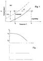
- FIG. 1 shows the concentration-temperature diagram of the solution.
- the first area is to the right of the solid line, that is bounded to the left of this, and represents the area of unsaturated Solution in which neither a nucleation process begins nor crystal growth takes place.
- a crystal growth whichever first of all presupposes the formation of a germ only in a supersaturated solution, since crystals already formed Due to the principle, falling below the saturation line (solid line) at least partially revert to the solution.
- the area of the supersaturated to the left of the solid line Solution can again be divided into two areas, the area located between the two lines the metastable zone forms, in which crystal growth but no nucleation process expires.
- the third area to the left of the dashed line forms the unstable zone, in which the only one of the three areas is a spontaneous one Nucleation process can begin.
- the two-phase flow or the segments of the solution contained therein have a concentration C 1 when entering the residence zone, the solution being converted from a state 1 to a state 2 by an abrupt decrease in temperature.
- State 1 can be an unsaturated state or a state in the metastable zone, ie state 1 can already contain a supersaturated solution. If there is a lack of germs, it is essential for the invention that state 2 is in the unstable zone, which according to the invention can be achieved by a corresponding sudden change in temperature.
- the nucleation process is initiated and the crystallization process that follows it is influenced by tracking the temperature, ie by targeted cooling.
- a nucleation process is not necessary because it is sufficient Crystallization nuclei are present, the procedure is carried out also possible if state 2 is in the metastable zone.
- the lingering section has small structures, whereby a the highest possible surface / volume ratio is sought.
- the lingering route is, for example, a hose, tubular or channel-shaped indwelling section with a diameter in Range from 0.5 to 10 mm, preferably from 1 mm to 2 mm, each according to the length of the stay, the dimensions between 10 cm to 200 m, preferably between 1 m to 25 m, Residence times in the range of a few seconds to a few hours can be realized.
- the small diameter of the lingering section or the large one Surface / volume ratio implies a low in the Lingering route led amount of solution, which only limited heat can save. For this reason and because of the surface-volume ratio can the one in the lingering section Solution from the outside in a very short time a defined temperature be imprinted, resulting in a quick temperature control is made possible. Also due to the small dimensions only very slight temperature gradients observed in the solution and This means that the temperature distribution is largely homogeneous be assumed. This should be emphasized in that it is for the Effectiveness of the crystallization is important that the local conditions in the dwell flow does not vary and is reflected in the total solution volume set the desired parameters.
- the product mixture After passing through the dwell section, the product mixture becomes one Separator supplied, in which the crystal particles generated by the remaining phases are separated so that at the end of the manufacturing process, after passing through the separator, the drug with the desired properties.
- the solid drug is in a solvent in which it is completely dissolves at a given temperature to form a Drug solution dissolved.
- the main advantage of this embodiment is that the Segmental emerging two-phase flow in the tubular Dwelling range that it goes through subsequently, no parabolic Speed profile (Hagen-Poiseulliesches law) but rather a rectangular profile averaged over time. This distinguishes the method according to the invention from that in conventional crystallizer processes in which sets a parabolic profile so that the speed in the Reduced pipe edge areas and finally directly on the wall becomes zero.
- the precipitant is added to the drug solution to make up the Solubility of the drug in the mixture at a given temperature to reduce, so that solid particles are formed.
- This The drug solution is in one of the segments upstream process step for the production of a possible homogeneous precipitation solution with a precipitant in a mixer Maschinenmengt.
- Micromixers are particularly well suited for this because they contain mass and Heat transfer processes run quickly and efficiently.
- Micromixer in the context of the present invention is a structure understand which dimensions are in the range of 10 ⁇ m to 1 mm, preferably between 25 ⁇ m to 200 ⁇ m.
- a mixture of the drug solution and the precipitant a precipitation solution of the highest possible homogeneity is required.
- the two fluids on the one hand the Drug solution and on the other hand the precipitant, after entering divided the mixer into individual streams using a microstructure.
- the Individual streams are, for example, lamellar and are made with the help of channels arranged in the microstructure layered in the way that a system of thin fluid lamella is created, in which alternately a fluid lamella of the drug solution Fiuidlamelle the precipitant is adjacent.
- the layered structure consists of a large number of slats Existing fluid system is fed to a mixing chamber in which one Mixing takes place by diffusion.
- the mixture according to the principle the diffusion can only take place in acceptably short times, if the structures of the mixer and thus the lamella thickness of the Individual currents are sufficiently small (preferably 10 to 200 ⁇ m).
- the thickness of the fluid lamellae crucially determines the time to compensate for the differences in concentration through diffusive Mixing is needed.
- the slat thickness is in the range of some ten micrometers, can be a complete mix and therefore one Homogeneity of the precipitation solution in the entire mixing volume already in can be realized in less than a second.
- the micromixer is preferably designed in such a way that it is based on can be easily heated and / or cooled. Flow rate and temperature in the micromixer are in the With regard to the nucleation process chosen so that nucleation does not take place in the mixer.
- a large number of Devices for heating and cooling the individual, described Components of the microreactor can be used.
- these are wire resistance heaters, electrical Heating foils, Peltier elements and heating and / or cooling devices, with a tempered fluid such as water, oil, air, Nitrogen and the like.
- a tempered fluid such as water, oil, air, Nitrogen and the like.
- infrared radiation can also be used and microwave heaters are used.
- Embodiments of the method in which Submicron-sized solid particles for nucleation in the mixer are added preferably the addition of the submicrometer Solid particles by using a precipitant, which contains colloid particles.
- Embodiments of the method are advantageous in which the temperature control in the residence zone takes place in such a way that an essentially constant supersaturation C 1 is present in the solution. This helps to achieve the object according to the invention of forming very small particles or crystals of small diameter.
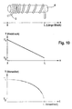
- FIG. 2 shows how the temperature T (t) is to be managed in order to obtain a constant supersaturation over time given a parabolic course of the concentration (FIG. 1) and assuming diffusion-controlled crystal growth (likewise FIG. 2).
- FIG. 3 shows schematically the structure of a microreactor Implementation of a first variant of the method.
- the microreactor consists of a micromixer 1, a segmenter 2 and one Lingering section 3.
- the drug solution 11 is included a precipitant 12 in the micromixer 1 to one if possible homogeneous precipitation solution 21 mixed.
- This precipitation solution 21 will fed to the segmenter 2 and with the aid of a transport medium 22 segmented.
- the one present after passing through the segmenter Two-phase flow is fed to the dwell section 3, in which the Crystallization takes place.
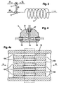
- Figure 4 shows the basic structure of a micromixer 1 with the Inlet openings 15 and 16 for the supply of the drug solution 11 on the one hand and the precipitant 12 on the other hand, and the Outlet opening 17 through which is generated in the micromixer 1 Precipitation solution 21 leaves the micromixer.
- the microstructure 13 is arranged with the the incoming fluid streams 11 and 12 are divided into individual streams become.
- the actual mixing chamber 14 is above this Microstructure 13 arranged. This takes place in this mixing chamber 14 Mixing to a homogeneous solution due to diffusion.
- FIG. 4a shows an enlargement of the between the Inlet openings 15 and 16 lying microstructure 13.
- Die Feed channels 131 and 132 for feeding the fluid flows into the Mixing chamber 14 and for dividing the incoming fluid flows into Partial streams are arranged in such a way that those separated by them Partial flows form an alternating system of thin fluid lamellae, alternately expressing that fluid lamellae of the drug solution 11 and fluid lamellae of the precipitant 12 alternately layered become.
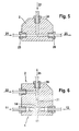
- Figure 5 shows schematically the structure of a segment 2 with the Entry openings 23 and 24 and the exit opening 26. Die through the Precipitation solution 21 supplied to segment 2 becomes inlet opening 23 with the help of the supplied through the inlet opening 24 Transport medium 22 segments and leaves the segment 2 as Two-phase flow 25.
- Figure 6 shows a second embodiment of a micromixer 1 with an integrated segmenter 2.
- the in the micromixer 1 entering fluid flows, the drug solution 11 on the one hand and that Precipitants 12, on the other hand, pass through the microstructure 13 of the Micromixer 1 in the mixing chamber 14 and after Mixing in the mixing chamber 14 as largely homogeneous Precipitation solution 21 fed to segment 2.
- segment 2 is the precipitation solution 21 with a second, with the precipitation solution 21 segmented immiscible fluid, which serves as carrier medium 22, the two-phase flow 25 generated thereby the segmenter 2 leaves through the outlet opening 26.
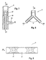
- FIG. 7 shows a segment 2 which comprises two tubes 27, 28 from which the smaller tube 28 in the larger tube 27 and to this is arranged coaxially.
- the precipitation solution 21 is by means of the small tube 28 introduced into the large tube 27 and through the lateral transport medium 22 fed through the inlet opening 24 segmented so that a two-phase flow 25 the segmenter 2 at Leaves end of the large tube 27.
- Figure 8 shows a further embodiment of a segmenter 2, at which the feed channels, the precipitation solution 21 on the one hand and the Feed the transport medium 22 on the other hand, form an angle that can vary between 0 and 180 ° and the one shown in FIG Embodiment is 90 °.
- Figure 9 shows a section of a tubular dwell section 3 in Cross-section.
- the structure of the stay section 3 is shown supplied two-phase flow 25. This consists preferably of same size fluid volume of precipitation solution 21, which with the help of Transport medium 22 are segmented.
- FIG. 9 Also shown in FIG. 9 are those in the segments of FIG Precipitation solution 21 flowing processes or the associated flow directions.
- the averaged over time Speeds result in a cross-section of the pipe Dwell section 3 even rectangular profile. It can be seen that under the flow conditions prevailing in the fluid segment no deposits on the inside walls of the pipe section 3 can form.
- FIG. 10 shows an exemplary embodiment of a stay section in the perspective view showing a tubular Dwell section 3 is wound on a cylindrical aluminum profile 4 is.
- the dwell section 3 can be cooled via the aluminum profile 4 or be heated.
- This temperature profile T (t) is determined on the one hand by the slope of the Dwell path 3 on the aluminum block 4 (see Figure 10 above) and on the other hand by the temperature profile T (L) in the aluminum block 4 (see Figure 10 middle) realized, in the present example the Temperature in the aluminum block 4 decreases linearly and the slope of the on the aluminum block wound retention path 3 increases.
- the slope of the wound stay section 3 and Temperature curve T (L) in the aluminum block 4 are the respective Adapt in individual cases. They depend on the one used Drug, the solution, the additional entry of Solid particles as crystal nuclei and the possibly used Precipitant.
- Drugs are montelukast and pramipexole.
- lactose glucose, Sucrose, mannitol, and / or trehalose are used.
- drugs solvent precipitant salt forms Water, methanol Alcohols (ethanol, propanol, isopropanol), ketones (acetone, butanone) Free bases Alcohols (ethanol, propanol, iso-propanol, tert-butanol), ketones (acetone, butanone) Water, methanol Alcohols (ethanol, propanol, isopropanol, tert-butanol), ketones (acetone, butanone) Water, methanol Alcohols (ethanol, propanol, isopropanol, tert-butanol), ketones (acetone, butanone) Water, methanol Alcohols (ethanol, propanol, isopropanol, tert-butanol), ketones (acetone, butanone) Water, methanol Alcohols (ethanol, propanol, isopropanol, tert-butanol), ketones (acetone, butanone) Water, methanol Alcohols (ethanol, propano
Abstract
Description
Die Erfindung betrifft ein Verfahren zur kontinuierlichen Herstellung inhalierfähiger Arzneistoffe.The invention relates to a process for continuous production inhalable drugs.
Im Rahmen der Erfindung ist unter dem Begriff "Arzneistoff" der wirksame Bestandteil eines Arzneimittels zu verstehen, der üblicherweise auch als Pharmakon oder Wirkstoff bezeichnet wird.In the context of the invention, the term "drug" is the to understand effective ingredient of a drug, usually is also referred to as a pharmaceutical or active ingredient.
Inhalativa erfordern eine bestimmte Erscheinungsform des Arzneistoffes. Zum Einsatz kommen in der Regel mikronisierte Arznei- bzw. Wirkstoffe in fester Form. Um die Inhalierfähigkeit des Arzneistoffes zu gewährleisten, werden hohe Anforderungen an die Teilchengröße, die Teilchengrößenverteilung, die Morphologie, die Stabilität und das Fließverhalten gestellt.Inhalatives require a specific form of the drug. Micronized medicinal or Active substances in solid form. To increase the inhalability of the drug ensure high particle size requirements that Particle size distribution, morphology, stability and that Flow behavior posed.
In der Regel gelangt nicht die gesamte inhalativ verabreichte Dosis des Arzneistoffes in die Lunge, sondern nur ein Teil dieser Dosis. Maßgeblichen Einfluß auf den Anteil des Arzneistoffes, der tatsächlich in die Lunge gelangt, hat die Teilchengröße. Aus diesem Grunde werden Teilchen bevorzugt, die einen Durchmesser kleiner 20µm, vorzugsweise kleiner 5µm und größer 0,3µm, aufweisen. Der Durchmesser des Teilchens sollte sich im angegebenen Fenster befinden und darüber hinaus eine möglichst enge Größenverteilung aufweisen. Größere Teilchen werden beim Einatmen bereits in den oberen Luftwegen abgeschieden, wohingegen kleinere Teilchen nicht in der Lunge deponiert werden und diese beim Ausatmen wieder verlassen. As a rule, not the entire inhaled dose of Drug into the lungs, but only part of this dose. Significant influence on the proportion of the drug that actually gets into the lungs has the particle size. For this reason particles with a diameter smaller than 20 µm are preferred preferably smaller than 5 µm and larger than 0.3 µm. The Diameter of the particle should be in the window indicated and also have the smallest possible size distribution exhibit. Larger particles are already inhaled in the deposited upper airways, whereas smaller particles are not in the lungs are deposited and exhaled again leave.
Unter Teilchendurchmesser im Rahmen der vorliegenden Erfindung ist der aerodynamische Partikeldurchmesser zu verstehen, wobei dieser definiert ist als Äquivalentdurchmesser einer Kugel der Dichte von 1 g/cm3, die die gleiche Sentimedationsgeschwindigkeit in Luft besitzt, wie das untersuchte Teilchen.Particle diameter in the context of the present invention is to be understood as the aerodynamic particle diameter, which is defined as the equivalent diameter of a sphere with a density of 1 g / cm 3 , which has the same sentimation rate in air as the particle under investigation.
Des weiteren werden hohe Anforderungen an die physikalische Stabilität der mikronisierten Arzneistoffteilchen gestellt. Die Teilchen sollten bei Umgebungsbedingungen vorzugsweise in der stabilen Kristallform vorliegen, um Agglomeration durch Phasenumwandung zu verhindern. Die Stabilität der Arzneistoffteilchen hat somit indirekten Einfluß auf die tatsächlich in die Lunge gelangte Arzneistoffmenge. Aus diesem Grunde werden hohe Anforderungen an die Stabilität des Arzneistoffes gestellt, um eine dauerhaft gleichbleibende Qualität, insbesondere eine zeitlich konstante Teilchengröße bzw. Größenverteilung, des Arzneistoffes zu gewährleisten. Gerade im Bereich der Pharmazie und der Verwendung von Arzneistoffen ist dieses Qualitätsmerkmal unerläßlich, weil die Wirkung des Arzneistoffes von der in die Lunge gelangten Dosis und somit, wie oben beschrieben, von der Teilchengröße und ihrer Größenverteilung abhängt.Furthermore, high demands are placed on the physical Stability of the micronized drug particles. The particles should preferably be in the stable at ambient conditions Crystal form to agglomerate through phase transition prevent. The stability of the drug particles is therefore indirect Influence on the amount of drug that actually gets into the lungs. Out for this reason, high demands on the stability of the Drug to ensure a consistently constant quality, in particular a temporally constant particle size or size distribution, to ensure the drug. Especially in the area of Pharmacy and the use of drugs is this Quality characteristic indispensable because the effect of the drug from the dose that entered the lungs and thus, as described above, of depends on the particle size and its size distribution.
Ähnliches gilt für die Morphologie der mikronisierten Teilchen, da die Beschaffenheit der Teilchenoberfläche direkten Einfluß auf die Neigung der Teilchen zur Agglomeration und somit indirekten Einfluß auf die Teilchengröße selbst bzw. die Haltbarkeit des Arzneistoffes hat.The same applies to the morphology of the micronized particles, since the The nature of the particle surface has a direct influence on the inclination of particles for agglomeration and thus indirect influence on the Particle size itself or the shelf life of the drug.
Dem mikronisierten Arzneistoff können Hilfsstoffe zugesetzt werden, mit denen die physiko-chemischen Eigenschaften eines Arzneimittels eingestellt werden, wobei diese die qualitätsbestimmenden Parameter, wie Bioverfügbarkeit, Wirksamkeit und Haltbarkeit in gewünschter Weise beeinflussen. Auxiliaries can be added to the micronized drug with which the physico-chemical properties of a drug can be set, these being the quality-determining parameters, such as bioavailability, effectiveness and shelf life in the desired Influence wise.
Neben der Teilchengröße und Größenverteilung des mikronisierten Arzneistoffs können Art, Teilchengröße und Megenverhältnis der zugesetzten Hilfsstoffe in entscheidender Weise die Arzneistoff-Dosis beeinflussen, die in die Lunge gelangt.In addition to the particle size and size distribution of the micronized Drug can type, particle size and ratio of the added excipients in a decisive way the drug dose influence that gets into the lungs.
Herkömmliche Verfahren zur Herstellung inhalierfähiger Arzneistoffe sind in der Regel, eine grob strukturierte Betrachtungsweise vorausgesetzt, zweistufig, wobei in einer ersten Stufe der Arzneistoff in fester, üblicherweise kristallinen Form hergestellt und dieser in einer zweiten Stufe im Rahmen eines Zerkleinerungsprozesses in mikronisierte Teilchen transformiert wird. Nach dem Stand der Technik kommen für den Zerkleinerungsprozeß Mahlprozesse zum Einsatz, wobei insbesondere Luftstrahlmahlen eine große Bedeutung erlangt hat, da es ökonomisch arbeitet, für eine Vielzahl von Substanzen anwendbar ist und eine einfache Abtrennung der gewünschten Teilchenfraktionen durch einen nachgeschalteten Zyklon-Abscheider erlaubt.Conventional processes for the manufacture of inhalable drugs are generally, provided a roughly structured approach, two-stage, in a first stage the drug in solid, usually produced in a crystalline form and this in a second Stage as part of a crushing process in micronized Particle is transformed. According to the state of the art come for the crushing process grinding processes used, wherein especially air jet milling has gained great importance as it works economically, is applicable for a variety of substances and easy separation of the desired particle fractions allowed by a downstream cyclone separator.
Nachteilig an dem nach dem Stand der Technik verwendeten Luftstrahlmahlen ist, daß die Feststoffteilchen prinzipbedingt einer erheblichen Krafteinwirkung während des Mahlprozesses ausgesetzt sind. Diese Krafteinwirkung induziert eine beträchtliche lokale Erwärmung und führt darüber hinaus zur Bildung amorpher Anteile. Aufgrund der lokalen Erwärmung eignet sich das Luftstrahlmahlen bzw. das Mahlen als Zerkleinerungsprozeß generell nicht für niedrigschmelzende, thermisch labile oder denaturierbare Stoffe.A disadvantage of that used in the prior art Air jet milling is that the solid particles are inherently one exposed to considerable force during the grinding process are. This force induces a considerable local Warming and also leads to the formation of amorphous parts. Due to the local heating, air jet grinding or grinding as a crushing process is generally not for low-melting, thermally labile or denaturable substances.
Darüber hinaus wird bei der Lagerung strahlgemahlener Arzneistoffe häufig eine Agglomeration beobachtet, da die durch den Mahlprozeß entstandenen amorphen Anteile rekristallisieren. In addition, when storing jet-milled drugs Agglomeration is frequently observed as a result of the grinding process recrystallize resulting amorphous portions.
Aus der WO 01/14036 ist ein Verfahren zu Herstellung eines inhalierfähigen Arzneistoffes bekannt. Hierbei wird eine Vorrichtung verwendet, in welcher zwei flüssige Ströme in vorgegebenen Volumenverhältnissen gezwungen werden, aufeinander zu stoßen. WO 01/14036 describes a method for producing a known inhalable drug. This is a device used in which two liquid streams in given Volume ratios are forced to collide.
Vor diesem Hintergrund ist es die Aufgabe der vorliegenden Erfindung ein Verfahren zur kontinuierlichen Herstellung inhalierfähiger Arzneistoffe bereitzustellen, bei dem die Einhaltung der genannten Anforderungen an Arzneistoffe sichergestellt ist und darüber hinaus die Nachteile der nach dem Stand der Technik verwendeten Verfahren vermieden werden.Against this background, it is the object of the present invention a process for the continuous production of inhalable drugs to provide compliance with the requirements mentioned of drugs is ensured and beyond that Disadvantages of the methods used according to the prior art be avoided.
Gelöst wird die Aufgabe durch ein kontinuierliches Verfahren zur Herstellung inhalierfähiger Arzneistoffe, welches folgende Verfahrensschritte umfaßt:
- Einsatz einer Arzneistoff-Lösung,
- Segmentierung der Lösung mittels eines Segmenters und eines Transportmediums,
- Einleiten und Führen des Kristallisationsprozesses in einer Verweilerstrecke mittels Aufprägen einer definierten Temperatur, wobei zunächst mittels einer sprunghaften Temperaturverringerung der Keimbildungsprozeß in der Art eingeleitet wird, daß die Lösung bzgl. der Temperatur T und der Konzentration C des in ihr gelösten Stoffes einen übersättigten, metastabilen oder labilen Zustand annimmt, und anschließend das Kristallwachstum durch gezielte Kühlung beinflußt wird, und
- Abscheiden der Kristallpartikel von den übrigen Phasen nach Durchlauf der Verweilerstrecke in einem Abscheider.
- Use of a drug solution,
- Segmentation of the solution using a segmenter and a transport medium,
- Initiation and control of the crystallization process in a retention zone by impressing a defined temperature, the nucleation process being initiated first by means of an abrupt decrease in temperature in such a way that the solution has an oversaturated, metastable or unstable state, and then the crystal growth is influenced by targeted cooling, and
- Separation of the crystal particles from the remaining phases after passing through the residence zone in a separator.
Erfindungsgemäß wird zunächst von einer Arzneistoff-Lösung ausgegangen. Es können bereits vorliegende Arzneistoff-Lösung verwendet werden, beispielsweise eine während der Arzneistoff-Herstellung ausfallende Lösung. According to the invention, a drug solution is initially assumed. Already existing drug solution can be used be, for example one during drug manufacture failed solution.
Diese Lösung wird im Anschluß einem Segmenter zugeführt und mit einem Transportmedium segmentiert. Bei dem Transportmedium handelt es sich um ein zweites, mit der Lösung nicht mischbares Fluid, mit dessen Hilfe die Lösung in Form diskreter Segmente in der Art unterteilt wird, daß die diskreten Segmente, welche vorzugsweise von gleichem Volumen sind, in einen aus dem Transportmedium bestehenden Trägerstom eingebracht werden. Das Transportmedium kann gasförmig oder flüssig sein, wobei sich in Versuchen gezeigt hat, daß mit Lösungsmitteldampf der Lösung gesättigte Luft besonders geeignet ist, um als Transportmedium zu dienen. Die beiden dem Segmenter zugeführten Ströme, daß heißt die Lösung einerseits und das Transportmedium andererseits, verlassen den Segmenter als segmentierte, vorzugsweise regelmäßig segmentierte Zweiphasenströmung.This solution is then fed to a segmenter and with segmented a transport medium. With the transport medium is a second fluid that is immiscible with the solution, with the help of which the solution in the form of discrete segments in Art is divided that the discrete segments, which are preferably of same volume, in one from the transport medium existing carrier current can be introduced. The transport medium can be gaseous or liquid, and experiments have shown that that particularly saturated air with solvent vapor of the solution is suitable to serve as a transport medium. The two of them Currents supplied to the segmenter are called the solution on the one hand and the transport medium on the other hand, leave the segment as segmented, preferably regularly segmented two-phase flow.
Die Abmessungen der Segmenterkanäle des für das erfindungsgemäße Verfahren vorzugsweise zu verwendenden Segmenters liegen im Bereich von 0,1 mm bis 5 mm, vorzugsweise zwischen 0,2 und 1 mm. Es handelt sich dabei also um kleinste Strukturen.The dimensions of the segment channels for the invention Processes to be used preferably are segmenters Range from 0.1 mm to 5 mm, preferably between 0.2 and 1 mm. So these are the smallest structures.
Darüberhinaus bietet es sich an, den Segmenter konstruktiv so zu gestalten, daß er in der Temperatur leicht steuerbar ist, das heißt leicht beheizt/gekühlt werden kann und mit ihm große Abkühlraten - Temperaturdifferenz pro Zeiteinheit - zu erzielen sind. Dies wird durch Ausbildung kleinster Strukturen unterstützt.Furthermore, it makes sense to constructively close the segment design that it is easily controllable in temperature, that is easy can be heated / cooled and with it high cooling rates - Temperature difference per unit of time - can be achieved. This is through Training of the smallest structures supported.
Des weiteren können die Flußraten der Lösung und des Transportmediums in weiten Grenzen variiert werden, wodurch direkt Einfluß auf die Ausbildung und damit die Gestalt der segmentierten Zweiphasenströmung genommen werden kann. Vorzugsweise erfolgt die Einstellung so, daß etwa gleichgroße Fluidsegmente von einer Länge von zwei- bis dreimal dem Kanaldurchmesser erzeugt werden. Furthermore, the flow rates of the solution and the transport medium can can be varied within wide limits, which directly influences the training and thus the shape of the segmented Two phase flow can be taken. Preferably done the setting so that approximately equal fluid segments of one Length of two to three times the channel diameter are generated.
Nach der Segmentierung wird die segmentierte Zweiphasenströmung einer Verweilerstrecke zugeführt. Die Verweilerstrecke dient der eigentlichen Herstellung des inhalierfähigen Arzneistoffes bzw. der zu produzierenden Teilchen mit den genannten Eigenschaften bezüglich der Teilchengröße, der Größenverteilung der Teilchen, der Morphologie und der Stabilität.After segmentation, the segmented two-phase flow fed a dwelling line. The lingering route serves the actual manufacture of the inhalable drug or producing particles with the mentioned properties with respect the particle size, the size distribution of the particles, the morphology and stability.
Bei Eintritt der Zweiphasenströmung in die Verweilerstrecke wird in einem ersten Schritt der Keimbildungsprozeß durch sprunghafte Temperaturverringerung eingeleitet. Zur näheren Erläuterung der in der Verweilerstrecke ablaufenden Vorgänge wird auf die Figur 1 verwiesen, die das Konzentrations-Temperatur-Diagramm der Lösung zeigt. In dem durch die y-Achse (Konzentration) und x-Achse (Temperatur) aufgespannten Quadranten sind zwei Kurven eingezeichnet, von denen eine durchgezogen und eine gestrichelt ist und durch die drei unterschiedliche Bereiche gebildet werden.When the two-phase flow enters the retention zone, in a first step of the nucleation process by leaps and bounds Temperature reduction initiated. For a more detailed explanation of the in the Processes that take place in the retention zone are referred to FIG. 1, which shows the concentration-temperature diagram of the solution. By doing through the y-axis (concentration) and x-axis (temperature) spanned quadrants, two curves are drawn, of which one solid and one dashed and through the three different areas are formed.
Der erste Bereich liegt rechts von der durchgezogenen Linie, wird also links von dieser begrenzt, und stellt den Bereich der ungesättigten Lösung dar, in welchem weder ein Keimbildungsprozeß einsetzt noch ein Kristallwachstum stattfindet. Ein Kristallwachstum, welches immer zunächst die Bildung eines Keimes voraussetzt, findet grundsätzlich erst in einer übersättigten Lösung statt, da bereits gebildete Kristalle bei Unterschreiten der Sättigungslinie (durchgezogene Linie) prinzipbedingt zumindest teilweise wieder in die Lösung übergehen.The first area is to the right of the solid line, that is bounded to the left of this, and represents the area of unsaturated Solution in which neither a nucleation process begins nor crystal growth takes place. A crystal growth, whichever first of all presupposes the formation of a germ only in a supersaturated solution, since crystals already formed Due to the principle, falling below the saturation line (solid line) at least partially revert to the solution.
Der links der durchgezogenen Linie liegende Bereich der übersättigten Lösung läßt sich wiederum in zwei Bereiche unterteilen, wobei der zwischen beiden Linien angesiedelte Bereich die metastabile Zone bildet, in der zwar ein Kristallwachstum aber kein Keimbildungsprozeß abläuft. Der dritte links von der gestrichelten Linie liegende Bereich bildet die labile Zone, in der als einzige der drei Bereiche ein spontaner Keimbildungsprozeß einsetzen kann.The area of the supersaturated to the left of the solid line Solution can again be divided into two areas, the area located between the two lines the metastable zone forms, in which crystal growth but no nucleation process expires. The third area to the left of the dashed line forms the unstable zone, in which the only one of the three areas is a spontaneous one Nucleation process can begin.
Die Zweiphasenströmung bzw. die in ihr enthaltenen Segmente der
Lösung weisen bei Eintritt in die Verweilerstrecke eine Konzentration C1
auf, wobei die Lösung durch eine sprunghafte Temperaturverringerung
von einem Zustand 1 in einen Zustand 2 überführt wird. Der Zustand 1
kann ein ungesättigter oder ein in der metastabilen Zone liegender
Zustand sein, das heißt es kann bereits im Zustand 1 eine übersättigte
Lösung vorliegen. Bei einem Mangel an Keimen ist es wesentlich für die
Erfindung, daß der Zustand 2 in der labilen Zone liegt, was
erfindungsgemäß durch eine entsprechend schlagartige Temperaturveränderung
realisiert werden kann. Durch Überführen der Lösung in
den labilen Zustand wird der Keimbildungsprozeß eingeleitet und der
sich an ihn anschließende Kristallisationsprozeß wird durch Nachführen
der Temperatur d.h. durch gezieltes Kühlen beeinflußt.The two-phase flow or the segments of the solution contained therein have a concentration C 1 when entering the residence zone, the solution being converted from a state 1 to a
Ist ein Keimbildungsprozeß nicht erforderlich, weil genügend
Kristallisationskeime vorliegen, ist die Durchführung des Verfahrens
auch möglich, wenn Zustand 2 in der metastabilen Zone liegt.A nucleation process is not necessary because it is sufficient
Crystallization nuclei are present, the procedure is carried out
also possible if
Erst durch die beschriebenen Maßnahmen ist eine gezielte Einflußnahme auf das Kristallwachstum möglich. Dies trägt wesentlich zur Lösung der erfindungsgemäßen Aufgabe bei. Sehr kleine Partikel mit geringem Durchmesser im Bereich weniger Mikrometer erhält man in der labilen Zone, daß heißt bei sehr hoher Übersättigung, wenn sehr schnell sehr viele Keime gebildet werden, die kaum wachsen.Only through the measures described is a targeted one Influence on crystal growth possible. This is essential to solve the problem of the invention. Very small particles with a small diameter in the range of a few micrometers is obtained in the unstable zone, that means with very high supersaturation, if very quickly a lot of germs are formed that hardly grow.
Aus diesem Grunde ist es erforderlich, die Verweilerstrecke für das erfindungsgemäße Verfahren konstruktiv so zu gestalten, daß sie in der Temperatur leicht steuerbar ist, das heißt leicht beheizt/gekühlt werden kann und mit ihr große Abkühlraten - Temperaturdifferenz pro Zeiteinheit - erzielbar sind. Daher eignen sich bei der Verweilerstrecke ebenfalls Strukturen im Bereich von einigen Millimetern bzw. Mikrometern.For this reason, it is necessary to make the stay for that To design the inventive method constructively so that it in the Temperature is easily controllable, that is, it can be easily heated / cooled can and with it large cooling rates - temperature difference per Unit of time - can be achieved. Therefore, are suitable for the lingering route also structures in the range of a few millimeters or Micrometers.
Bei der Kristallisation nach dem Stand der Technik wird die beschriebene Vorgehensweise mit der sprunghaften Verlagerung der Zustandsgrößen vermieden, da durch die in kurzer Zeit frei werdende Kristallisationswärme Temperaturschwankungen in der Lösung hervorgerufen werden, die zu undefinierten Wachstumsbedingungen führen. Im Gegensatz hierzu kann bei dem erfindungsgemäßen Verfahren durch Verwendung von Apparaturen mit Dimensionen im Millimeter- oder Mikrometerbereich die Temperatur in der Lösung jederzeit exakt geregelt werden.In the crystallization according to the prior art, the described procedure with the sudden shift of the State variables avoided, as they are released in a short time Heat of crystallization Temperature fluctuations in the solution are caused, the under-defined growth conditions to lead. In contrast, can be in the inventive Process using equipment with dimensions in the Millimeter or micrometer range the temperature in the solution can be precisely regulated at all times.
Daher weist die für das erfindungsgemäße Verfahren verwendete Verweilerstrecke wie bereits erwähnt kleine Strukturen auf, wobei ein möglichst hohes Oberflächen-/Volumenverhältnis angestrebt wird. Bei der Verweilerstrecke handelt es sich beispielsweise um eine schlauch-, rohr- oder kanalförmige Verweilerstrecke mit einem Durchmesser im Bereich von 0,5 bis 10 mm, vorzugsweise von 1 mm bis 2 mm, wobei je nach der Länge der Verweilerstrecke, die Ausmaße zwischen 10 cm bis 200 m, vorzugsweise zwischen 1 m bis 25 m, aufweisen kann, Verweilzeiten im Bereich von einigen Sekunden bis zu einigen Stunden realisiert werden können.Therefore, the one used for the method according to the invention As already mentioned, the lingering section has small structures, whereby a the highest possible surface / volume ratio is sought. at the lingering route is, for example, a hose, tubular or channel-shaped indwelling section with a diameter in Range from 0.5 to 10 mm, preferably from 1 mm to 2 mm, each according to the length of the stay, the dimensions between 10 cm to 200 m, preferably between 1 m to 25 m, Residence times in the range of a few seconds to a few hours can be realized.
Der geringe Durchmesser der Verweilerstrecke bzw. das große Oberflächen-/Volumenverhältnis impliziert eine geringe in der Verweilerstrecke geführte Lösungsmenge, welche nur begrenzt Wärme speichern kann. Aus diesem Grunde und aufgrund des Oberflächen-Nolumenverhältnises kann der in der Verweilerstrecke befindlichen Lösung von außen in sehr kurzer Zeit eine definierte Temperatur aufgeprägt werden, wodurch eine schnelle Temperaturführung ermöglicht wird. Ebenfalls aufgrund der geringen Abmessungen werden nur sehr geringe Temperaturgradienten in der Lösung beobachtet und somit kann von einer weitestgehend homogenen Temperaturverteilung ausgegangen werden. Dies ist insofern hervorzuheben, da es für die Effektivität der Kristallisation wichtig ist, daß die lokalen Bedingungen in der Verweilerströmung nicht variieren und sich im gesamten Lösungsvolumen die gewünschten Parameter einstellen.The small diameter of the lingering section or the large one Surface / volume ratio implies a low in the Lingering route led amount of solution, which only limited heat can save. For this reason and because of the surface-volume ratio can the one in the lingering section Solution from the outside in a very short time a defined temperature be imprinted, resulting in a quick temperature control is made possible. Also due to the small dimensions only very slight temperature gradients observed in the solution and This means that the temperature distribution is largely homogeneous be assumed. This should be emphasized in that it is for the Effectiveness of the crystallization is important that the local conditions in the dwell flow does not vary and is reflected in the total solution volume set the desired parameters.
Entgegen den in dem Stand der Technik verwendeten Verfahren treten
bei dem erfindungsgemäßen Verfahren keine unerwünschten
Temperaturschwankungen auf, da die Temperatur in der Lösung von
außen gezielt und schnell eingestellt werden kann und damit der
Keimbildungsprozeß und das Kristallwachstum exakt gesteuert werden
können. Würde die Lösung bei Verwendung von herkömmlichen
Kristallisatoren entsprechend Figur 1 von Zustand 1 in Zustand 2 so
überführt, daß eine hohe Übersättigung eintritt, käme es zu nicht
beeinflußbaren Temperaturschwankungen, da der in Zustand 2
ablaufende Keimbildungsprozeß und die bei hoher Keimzahl
entstehende, erhebliche Kristallisationswärme den Zustand hin zu
höheren Temperaturen verschieben würde und ein Gegensteuern in
Form eines Kühlens aufgrund der konstruktiven Abmessungen
herkömmlicher Kristallisatoren zu periodischen Temperaturschwankungen
führen würde.Oppose the methods used in the prior art
no undesirable in the method according to the invention
Temperature fluctuations due to the temperature in the solution of
can be set quickly and precisely on the outside and thus the
Nucleation process and crystal growth can be precisely controlled
can. Would be the solution when using conventional
Crystallizers corresponding to Figure 1 from state 1 in
Nach Durchlaufen der Verweilerstrecke wird das Produktgemisch einem Abscheider zugeführt, in welchem die erzeugten Kristallpartikel von den übrigen Phasen getrennt werden, so daß am Ende des Herstellungsverfahrens, nach Durchlaufen des Abscheiders der Arzneistoff mit den gewünschten Eigenschaften vorliegt. After passing through the dwell section, the product mixture becomes one Separator supplied, in which the crystal particles generated by the remaining phases are separated so that at the end of the manufacturing process, after passing through the separator, the drug with the desired properties.
Vorteilhaft sind Verfahren, bei denen die Arzneistoff-Lösung unter Auflösen des festen Arzneistoffes in einem Lösungsmittel zur Bildung einer solchen Arzneistoff-Lösung bereitgestellt wird.Processes in which the drug solution is below are advantageous Dissolving the solid drug in a solvent for formation such a drug solution is provided.
Dabei wird der feste Arzneistoff in einem Lösungsmittel, in dem er sich bei vorgegebener Temperatur vollständig löst, zur Bildung einer Arzneistoff-Lösung aufgelöst.The solid drug is in a solvent in which it is completely dissolves at a given temperature to form a Drug solution dissolved.
Vorteilhaft sind Verfahren, bei denen
- die Segmentierung der Lösung mittels eines Segmenters und eines Transportmediums unter Ausbildung von Plug-Flow-Bedingungen erfolgt.
- the solution is segmented using a segmenter and a transport medium with the formation of plug-flow conditions.
Wesentlicher Vorteil dieser Ausführungsform ist, daß die aus dem Segmenter austretende Zweiphasenströmung in der rohrförmigen Verweilerstrecke, die sie im Anschluß durchläuft, kein parabolisches Geschwindigkeitsprofil (Hagen-Poiseulliesches-Gesetz) ausbildet, sondern sich ein über die Zeit gemitteltes Rechteckprofil einstellt. Dies unterscheidet das erfindungsgemäße Verfahren von den in herkömmliche Kristallisatoren ablaufenden Verfahren, bei denen sich ein parabolisches Profil einstellt, so daß sich die Geschwindigkeit in den Rohrrandbereichen verringert und schließlich direkt an der Wand zu Null wird.The main advantage of this embodiment is that the Segmental emerging two-phase flow in the tubular Dwelling range that it goes through subsequently, no parabolic Speed profile (Hagen-Poiseulliesches law) but rather a rectangular profile averaged over time. This distinguishes the method according to the invention from that in conventional crystallizer processes in which sets a parabolic profile so that the speed in the Reduced pipe edge areas and finally directly on the wall Becomes zero.
Als Folge dieses parabolischen Geschwindigkeitsprofils kommt es an der Rohrinnenwand der herkömmlichen Kristallisatoren zu Ablagerungen insbesondere von weiter wachsenden Kristallen, wodurch die Kristallisatoren letztendlich verstopfen bzw. sich zu setzen.As a result of this parabolic speed profile, it matters the inner wall of the conventional crystallizers Deposits in particular of crystals growing further, whereby the crystallizers ultimately clog or settle.
Bezüglich der Plug-Flow-Bedingungen sei auf Figur 9 verwiesen, in dem die in den Volumensegmenten vorliegenden Strömungen bzw. With regard to the plug flow conditions, reference is made to FIG. 9, in to which the flows or in the volume segments
Strömungsrichtungen eingezeichnet sind. Die Strömungsvorgänge in den Segmenten unterstützen die Homogenisierung der Lösung und wirken der Ausbildung von Konzentrationsunterschieden im Inneren und an der Wand entgegen. Des weiteren wird ein Verstopfen durch Kristall-Ablagerung an den Innenwänden der Verweilerstrecke vermieden.Flow directions are shown. The flow processes in the segments support the homogenization of the solution and affect the formation of concentration differences inside and against the wall. Furthermore, clogging due to crystal deposition avoided on the inner walls of the lingering section.
Vorteilhaft sind Ausführungsformen des Verfahrens, die dadurch gekennzeichnet sind, daß
- die Arzneistoff-Lösung in einem Mischer mit einem Fällungsmittel zu einer homogenen Fällungslösung vermengt wird und diese Fällungslösung das weitere Verfahren durchläuft.
- the drug solution is mixed in a mixer with a precipitant to form a homogeneous precipitation solution and this precipitation solution goes through the further process.
Das Fällungsmittel wird der Arzneistoff-Lösung zugemischt, um die Löslichkeit des Arzneistoffs in der Mischung bei gegebener Tempertur zu vermindern, so daß Festkörperpartikel gebildet werden. Diese Arnzeistoff-Lösung wird dabei in einem dem Segmenter vorgeschalteten Verfahrensschritt zur Herstellung einer möglichst homogenen Fällungslösung mit einem Fällungsmittel in einem Mischer durchmengt.The precipitant is added to the drug solution to make up the Solubility of the drug in the mixture at a given temperature to reduce, so that solid particles are formed. This The drug solution is in one of the segments upstream process step for the production of a possible homogeneous precipitation solution with a precipitant in a mixer durchmengt.
Mikromischer eignen sich hierzu besonders gut, da in ihnen Masse- und Wärmetransportvorgänge schnell und effizient ablaufen. Unter Mikromischer im Rahmen der vorliegenden Erfindung ist eine Struktur zu verstehen, welche Dimensionen im Bereich von 10µm bis 1 mm, vorzugsweise zwischen 25µm bis 200µm, aufweist.Micromixers are particularly well suited for this because they contain mass and Heat transfer processes run quickly and efficiently. Under Micromixer in the context of the present invention is a structure understand which dimensions are in the range of 10 µm to 1 mm, preferably between 25 µm to 200 µm.
Zur Herstellung von mikronisierten und inhalierfähigen Arzneistoffen ist eine Vermischung der Arzneistoff-Lösung und dem Fällungsmittel zu einer Fällungslösung von möglichst hoher Homogenität erforderlich. Ein Mikromischer mit seinen filigranen Strukturen eignet sich hierfür in besonderem Maße. Bei ihm werden die beiden Fluide, einerseits die Arzneistoff-Lösung und anderseits das Fällungsmittel, nach Eintritt in den Mischer mittels einer Mikrostruktur in Einzelströme aufgeteilt. Die Einzelströme sind beispielsweise lamellenförmig und werden mit Hilfe von in der Mikrostruktur angeordneten Kanälen in der Art geschichtet, daß ein System aus dünnen Fluidlamellen entsteht, bei welchem abwechselnd eine Fluidlamelle der Arzneistoff-Lösung einer Fiuidlamelle des Fällungsmittels benachbart ist. Dabei beträgt die Lamellendichte im Mikromischer 10 bis 1000, vorzugsweise 20 bis 500 pro cm. Das so geschichtete, aus einer Vielzahl von Lamellen bestehende Fluidsystem wird einer Mischkammer zugeführt, in der eine Vermischung durch Diffusion erfolgt. Die Mischung nach dem Prinzip der Diffusion kann nur in akzeptabel kurzen Zeiten vollzogen werden, wenn die Strukturen des Mischers und damit die Lamellendicke der Einzelströme genügend klein sind (vorzugsweise 10 bis 200 µm).For the production of micronized and inhalable drugs a mixture of the drug solution and the precipitant a precipitation solution of the highest possible homogeneity is required. On Micromixer with its filigree structures is suitable for this special measure. With him the two fluids, on the one hand the Drug solution and on the other hand the precipitant, after entering divided the mixer into individual streams using a microstructure. The Individual streams are, for example, lamellar and are made with the help of channels arranged in the microstructure layered in the way that a system of thin fluid lamella is created, in which alternately a fluid lamella of the drug solution Fiuidlamelle the precipitant is adjacent. The is Lamella density in the micromixer 10 to 1000, preferably 20 to 500 per cm. The layered structure consists of a large number of slats Existing fluid system is fed to a mixing chamber in which one Mixing takes place by diffusion. The mixture according to the principle the diffusion can only take place in acceptably short times, if the structures of the mixer and thus the lamella thickness of the Individual currents are sufficiently small (preferably 10 to 200 µm).
Die Dicke der Fluidlamellen bestimmt in entscheidender Weise die Zeit, die zum Ausgleich der Konzentrationsunterschiede durch diffusive Vermischung benötigt wird. Liegt die Lamellendicke im Bereich einiger zehn Mikrometer, kann eine komplette Vermischung und damit eine Homogenität der Fällungslösung im gesamten Mischvolumen bereits in einer Zeit unter einer Sekunde realisiert werden.The thickness of the fluid lamellae crucially determines the time to compensate for the differences in concentration through diffusive Mixing is needed. The slat thickness is in the range of some ten micrometers, can be a complete mix and therefore one Homogeneity of the precipitation solution in the entire mixing volume already in can be realized in less than a second.
Der Mikromischer ist vorzugsweise in der Art ausgeführt, daß er auf einfache Weise beheizt und/oder gekühlt werden kann. Durchflußgeschwindigkeit und Temperatur im Mikromischer werden im Hinblick auf den Keimbildungsprozeß so gewählt, daß eine Keimbildung im Mischer nicht stattfindet.The micromixer is preferably designed in such a way that it is based on can be easily heated and / or cooled. Flow rate and temperature in the micromixer are in the With regard to the nucleation process chosen so that nucleation does not take place in the mixer.
An dieser Stelle sei darauf hingewiesen, daß eine Vielzahl von Vorrichtungen zum Heizen und Kühlen der einzelnen, beschriebenen Bauelemente des Mikroreaktors verwendet werden können. Insbesondere sind dies Draht-Widerstandsheizungen, elektrische Heizfolien, Peltier-Elemente sowie Heiz- und/oder Kühlvorrichtungen, die mit einem temperierten Fluid wie beispielsweise Wasser, Öl, Luft, Stickstoff und dergl. arbeiten. Daneben können auch Infrarot-Strahlung und Mikrowellenheizungen eingesetzt werden.At this point it should be noted that a large number of Devices for heating and cooling the individual, described Components of the microreactor can be used. In particular, these are wire resistance heaters, electrical Heating foils, Peltier elements and heating and / or cooling devices, with a tempered fluid such as water, oil, air, Nitrogen and the like. In addition, infrared radiation can also be used and microwave heaters are used.
Vorteilhaft sind auch Ausführungsformen des Mikroreaktors, bei denen auf der Basis einer geätzten Platte, die eine elektrische Heizung aufweist, ein Mikroreaktor in diese Platte implementiert ist.Embodiments of the microreactor in which based on an etched plate that has an electric heater has, a microreactor is implemented in this plate.
Vorteilhaft sind Ausführungsformen des Verfahrens, bei denen submikrometergroße Festkörperpartikel zur Keimbildung im Segmenter eingetragen werden, wobei vorzugsweise
- der Eintrag der submikrometergroßen Festkörperpartikel bei der Verwendung von Luft als Transportmedium vorzugsweise durch Zugabe eines Hilfsstoffes oder des Arzneisstoffes als Staubaerosol in den Luftstrom erfolgt, und
- bei Verwendung eines flüssigen Transportmediums submikrometergroße Festkörperpartikel in Form von Hilfsstoff- oder Arzneistoffpartikeln dem Transportmedium zugesetzt werden, oder
- bei Verwendung eines flüssigen Transportmediums submikrometergroße Festkörperpartikel in Form von Hilfsstoff-Kolloiden dem Transportmedium zugesetzt werden.
- the submicron-sized solid particles are preferably introduced into the air stream when air is used as the transport medium, by adding an auxiliary or the drug as a dust aerosol, and
- when using a liquid transport medium, submicron-sized solid particles in the form of excipient or drug particles are added to the transport medium, or
- when using a liquid transport medium, submicron-sized solid particles in the form of auxiliary colloids are added to the transport medium.
Durch Eintrag von submikrometergroßen Festkörperpartikeln läßt sich der Kristallisierungsprozeß besser kontrollieren. Durch den Eintrag von Kristallkeimen kann der Arbeitsbereich auch auf den metastabilen Bereich (bei geringeren Übersättigungsverhältnissen) erweitert werden. Bei den drei genannten Varianten des Feststoffpartikeleintrages werden bei der im Segmenter erzeugten Zweiphasen- strömung als Kristallisationskeime dienende Feststoffpartikel von außen, d.h. vom Transportmedium, in die segmentierte Lösung eingetragen.By entering submicron-sized solid particles better control the crystallization process. By entering The work area can also germinate on the metastable Range (with lower supersaturation ratios) can be expanded. With the three mentioned variants of the entry of solid particles with the two-phase flow generated in the segment as Solid particles serving crystallization nuclei from the outside, i.e. from Transport medium, entered in the segmented solution.
Vorteilhaft sind Ausführungsformen des Verfahrens, bei dem submikrometergroße Festkörperpartikel zur Keimbildung im Mischer zugegeben werden, wobei vorzugsweise die Zugabe der submikrometergroßen Festkörperpartikel durch Verwendung eines Fällungsmittels, welches Kolloidpartikel enthält, erfolgt.Embodiments of the method in which Submicron-sized solid particles for nucleation in the mixer are added, preferably the addition of the submicrometer Solid particles by using a precipitant, which contains colloid particles.
Vorteilhaft sind Ausführungsformen des Verfahrens, bei denen die Temperaturführung in der Verweilerstrecke in der Art erfolgt, daß eine im wesentlichen konstante Übersättigung C1 in der Lösung vorliegt. Dies trägt zur Lösung der erfindungsgemäßen Aufgabe bei, sehr kleine Teilchen bzw. Kristalle von geringem Durchmeser zu bilden. Figur 2 zeigt wie die Temperatur T(t) zu führen ist, um bei einem parabolischen Verlauf der Konzentration (Figur 1) und unter der Annahme eines diffusionskontrollierten Kristallwachstums eine konstante Übersättigung über der Zeit zu erhalten (ebenfalls Figur 2).Embodiments of the method are advantageous in which the temperature control in the residence zone takes place in such a way that an essentially constant supersaturation C 1 is present in the solution. This helps to achieve the object according to the invention of forming very small particles or crystals of small diameter. FIG. 2 shows how the temperature T (t) is to be managed in order to obtain a constant supersaturation over time given a parabolic course of the concentration (FIG. 1) and assuming diffusion-controlled crystal growth (likewise FIG. 2).
Die Erfindung wird anhand verschiedener Ausführungsbeispiele gemäß den Zeichnungsfiguren näher erläutert. Hierbei zeigt:
- Figur 1
- das Konzentrations-Temperatur-Diagramm der in die Verweilerstrecke eintretenden Lösung,
Figur 2- die Temperaturführung T(t) einer Ausführungsform des erfindungsgemäßen Verfahrens zur Einstellung einer konstanten Übersättigung C (t),
Figur 3- schematisch eine Ausführungsform eines Mikroreaktors zur Durchführung des erfindungsgemäßen Verfahrens,
- Figur 4
- einen Mikromischer des Mikroreaktors gemäß einer ersten Ausführungsform im Querschnitt,
- Figur 4a
- eine Vergrößerung der Strukturen der Kanäle des in Figur 4 dargestellten Mikromischers,
Figur 5- einen Segmenter des Mikroreaktors gemäß einer ersten Ausführungsform im Querschnitt,
- Figur 6
- einen Mikromischer des Mikroreaktors gemäß einer zweiten Ausführungsform mit integriertem Segmenter im Querschnitt,
- Figur 7
- einen Segmenter des Mikroreaktors gemäß einer dritten Ausführungsform im Querschnitt,
- Figur 8
- einen Segmenter des Mikroreaktors gemäß einer vierten Ausführungsform im Querschnitt,
- Figur 9
- die Verweilerstrecke einer Ausführungsform eines Mikroreaktors im Querschnitt mit der in der Verweilerstrecke geführten Zweiphasenströmung, und
- Figur 10
- eine Verweilerstrecke einer Ausführungsform eines Mikroreaktors mit den Temperaturverläufen über die Länge der Verweilerstrecke und über die Zeit.
- Figure 1
- the concentration-temperature diagram of the solution entering the retention zone,
- Figure 2
- the temperature control T (t) of an embodiment of the method according to the invention for setting a constant supersaturation C (t),
- Figure 3
- schematically an embodiment of a microreactor for carrying out the method according to the invention,
- Figure 4
- a micro mixer of the microreactor according to a first embodiment in cross section,
- Figure 4a
- an enlargement of the structures of the channels of the micromixer shown in FIG. 4,
- Figure 5
- a segment of the microreactor according to a first embodiment in cross section,
- Figure 6
- 2 shows a micromixer of the microreactor according to a second embodiment with an integrated segment in cross section,
- Figure 7
- 3 shows a segment of the microreactor according to a third embodiment in cross section,
- Figure 8
- 3 shows a segment of the microreactor according to a fourth embodiment in cross section,
- Figure 9
- the dwell section of an embodiment of a microreactor in cross section with the two-phase flow carried in the dwell section, and
- Figure 10
- a dwell section of an embodiment of a microreactor with the temperature profiles over the length of the dwell section and over time.
Die Figuren 1 und 2 wurden bereits oben beschrieben.Figures 1 and 2 have already been described above.
Figur 3 zeigt schematisch den Aufbau eines Mikroreaktors zur
Durchführung einer ersten Variante des Verfahrens. Der Mikroreaktor
besteht aus einem Mikromischer 1, einem Segmenter 2 und einer
Verweilerstrecke 3. Dabei wird zunächst die Arzneistoff-Lösung 11 mit
einem Fällungsmittel 12 im Mikromischer 1 zu einer möglichst
homogenen Fällungslösung 21 vermischt. Diese Fällungslösung 21 wird
dem Segmenter 2 zugeführt und mit Hilfe eines Transportmediums 22
segmentiert. Die nach Durchlaufen des Segmenters vorliegende
Zweiphasenströmung wird der Verweilerstrecke 3 zugeführt, in der die
Kristallisation erfolgt.Figure 3 shows schematically the structure of a microreactor
Implementation of a first variant of the method. The microreactor
consists of a micromixer 1, a
Figur 4 zeigt den prinzipiellen Aufbau eines Mikromischers 1 mit den
Eintrittsöffnungen 15 und 16 für die Zuführung der Arzneistoff-Lösung
11 einerseits und dem Fällungsmittel 12 andererseits, sowie der
Austrittsöffnung 17, durch die die im Mikromischer 1 erzeugte
Fällungslösung 21 den Mikromischer verläßt. Zwischen den
Eintrittsöffnungen 15 und 16 ist die Mikrostruktur 13 angeordnet, mit der
die eintretenden Fluidströme 11 und 12 in Einzelströme aufgeteilt
werden. Die eigentliche Mischkammer 14 ist oberhalb dieser
Mikrostruktur 13 angeordnet. In dieser Mischkammer 14 erfolgt die
Durchmischung zu einer homogenen Lösung infolge Diffusion.Figure 4 shows the basic structure of a micromixer 1 with the
In Figur 4a dargestellt ist eine Vergrößerung der zwischen den
Eintrittsöffnungen 15 und 16 liegenden Mikrostruktur 13. Die
Zuführkanäle 131 und 132 zur Zuführung der Fluidströme in die
Mischkammer 14 und zur Unterteilung der eintretenden Fluidströme in
Teilströme sind in der Art angeordnet, daß die durch sie aufgetrennten
Teilströme ein alternierendes System aus dünnen Fluidlamellen bilden,
wobei alternierend ausdrückt, daß Fluidlamellen der Arzneistofflösung
11 und Fluidlamellen des Fällungsmittels 12 abwechselnd geschichtet
werden.FIG. 4a shows an enlargement of the between the
Figur 5 zeigt schematisch den Aufbau eines Segmenters 2 mit den
Eintrittsöffnungen 23 und 24 und der Austrittsöffnung 26. Die durch die
Eintrittsöffnung 23 dem Segmenter 2 zugeführte Fällungslösung 21 wird
mit Hilfe des durch die Eintrittsöffnung 24 zugeführten
Transportmediums 22 segmentiert und verläßt den Segmenter 2 als
Zweiphasenströmung 25.Figure 5 shows schematically the structure of a
Figur 6 zeigt ein zweites Ausführungsbeispiel eines Mikromischers 1 mit
einem integrierten Segmenter 2. Die in den Mikromischer 1
eintretenden Fluidströme, die Arzneistoff-Lösung 11 einerseits und das
Fällungsmittel 12 andererseits gelangen durch die Mikrostruktur 13 des
Mikromischers 1 in die Mischkammer 14 und werden nach
Durchmischung in der Mischkammer 14 als weitestgehend homogene
Fällungslösung 21 dem Segmenter 2 zugeführt. Im Segmenter 2 wird
die Fällungslösung 21 mit einem zweiten, mit der Fällungslösung 21
nicht mischbaren Fluid, das als Trägermedium 22 dient, segmentiert,
wobei die dadurch erzeugte Zweiphasenströmung 25 den Segmenter 2
durch die Austrittsöffnung 26 verläßt.Figure 6 shows a second embodiment of a micromixer 1 with
an
Figur 7 zeigt einen Segmenter 2, der zwei Rohre 27,28 umfaßt, von
denen das kleinere Rohr 28 in dem größeren Rohr 27 und zu diesem
koaxial angeordnet ist. Dabei wird die Fällungslösung 21 mittels des
kleinen Rohres 28 in das große Rohr 27 eingeleitet und durch das
seitliche durch die Eintrittsöffnung 24 zugeführte Transportmedium 22
segmentiert, so daß eine Zweiphasenströmung 25 den Segmenter 2 am
Ende des großes Rohres 27 verläßt.FIG. 7 shows a
Figur 8 zeigt ein weiteres Ausführungsbeispiel eines Segmenters 2, bei
dem die Zuführkanäle, die die Fällungslösung 21 einerseits und das
Transportmedium 22 andererseits zuführen, einen Winkel bilden, der
zwischen 0 und 180° variieren kann und bei dem in Figur 8 gezeigten
Ausführungsbeispiel 90° beträgt. Figure 8 shows a further embodiment of a
Figur 9 zeigt einen Ausschnitt einer rohrförmigen Verweilerstrecke 3 im
Querschnitt. Dargestellt ist der Aufbau der der Verweilerstrecke 3
zugeführten Zweiphasenströmung 25. Diese besteht aus vorzugsweise
gleichgroßen Fluidvolumen von Fällungslösung 21, die mit Hilfe des
Transportmediums 22 segmentiert sind.Figure 9 shows a section of a
Ebenfalls in Figur 9 dargestellt sind die in den Segmenten der
Fällungslösung 21 ablaufenden Strömungsvorgänge bzw. die
dazugehörigen Strömungsrichtungen. Die über die Zeit gemittelten
Geschwindigkeiten ergeben einen über den Rohrquerschnitt der
Verweilerstrecke 3 gleichmäßiges Rechteckprofil. Ersichtlich wird, daß
sich unter den im Fluidsegment herrschenden Strömungsbedingungen
keine Ablagerungen an den Rohrinnenwänden der Verweilerstrecke 3
bilden können.Also shown in FIG. 9 are those in the segments of
Figur 10 zeigt ein Ausführungsbeispiel einer Verweilerstrecke in der
perspektivischen Ansicht, bei der eine schlauchförmige
Verweilerstrecke 3 auf ein zylinderförmiges Aluminiumprofil 4 gewickelt
ist. Die Verweilerstrecke 3 kann über das Aluminiumprofil 4 gekühlt bzw.
geheizt werden.FIG. 10 shows an exemplary embodiment of a stay section in the
perspective view showing a
Wie bereits erwähnt ist es eine Ausführungsform des Verfahrens, in der
Verweilerstrecke 3 eine im wesentlichen konstante Übersättigung C1
(siehe Figur 2 unten) in der Lösung zu realisieren. Dies wird mit einem
Temperaturprofil erreicht, bei dem der Temperaturgradient mit der Zeit
betragsmäßig zunimmt (siehe Figur 2 oben und Figur 10 unten).As already mentioned, it is an embodiment of the method to achieve an essentially constant supersaturation C 1 (see FIG. 2 below) in the solution in the
Dieser Temperaturverlauf T(t) wird einerseits durch die Steigung der
Verweilerstrecke 3 auf dem Aluminiumblock 4 (siehe Figur 10 oben) und
andererseits durch das Temperaturprofil T(L) im Aluminiumblock 4
(siehe Figur 10 Mitte) realisiert, wobei im vorliegenden Beispiel die
Temperatur im Aluminiumblock 4 linear abnimmt und die Steigung der
auf den Aluminiumblock aufgewickelten Verweilerstrecke 3 zunimmt.This temperature profile T (t) is determined on the one hand by the slope of the
Die Steigung der aufgewickelten Verweilerstrecke 3 und der
Temperaturverlauf T(L) im Aluminiumblock 4 sind dem jeweiligen
Einzelfall anzupassen. Sie sind abhängig von dem verwendeten
Arzneistoff, der Lösung, dem zusätzlichen Eintrag von
Festkörperpartikeln als Kristallkeime und dem eventuell eingesetzten
Fällungsmittel.The slope of the
Im folgenden werden für die Wirkstoffe, die Hilfsstoffe, die Lösungs- und Fällungsmittel Beispiele angeführt.In the following, the active substances, the auxiliary substances, the solvents and Precipitant examples given.
Als Arzneistoffe bzw. Wirkstoffe werden eingesetzt:
- als Anticholinergika: Ipratropiumbromid, Tiotropiumbromid, Tiotropiumbromid-Monohydrat,
- als Betasympathomimetica: Bambuterol, Bitolterol, Carbuterol, Formoterol, Clenbuterol, Fenoterol, Hexoprenalin, Procaterol, Ibuterol, Pirbuterol, Tulobuterol, Reproteroi, Salbutamol, Sulfonterol, Terbutalin, Orciprenalin, 1-(2-Fluor-4-hydroxyphenyl)-2-[4-( 1-benzimidazolyi)-2-methyl-2-butylamino]ethanol,erythro-5'-Hydroxy-8'-(1-hydroxy-2-isopropylaminobutyl)-2H-1,4-benzoxazin-3-(4H)-on, 1-(4-Amino-3-chlor-5-trifluormethylphenyl)-2-tert.-butyl-amino)ethanol,1-(4-Ethoxycarbonylamino-3-cyan-5-fluorphenyl)-2-(tert.butylamino)ethanol,
- als Antiallergika: Dinatriumcromglicat, Nedocromil, Epinastin, und
- als Steroide: Flunisolid, Dexamethason-21-isonicotinat, Seratrodast, Mycophenolate mofetil, Pranlukast, Zileuton, Butixocort, Budesonid, Deflazacort, Fluticason, Proedrol, Mometasin furoat, Tipredan, Beclometason (bzw. das17, 21-Dipropionat), Beclomethason, Douglas, Icomethason enbutat, Ciclometason, Cloprednol, Fluocortin butyl, Halometason, Deflazacort, Alclometason, Ciclometason, Alisactid, Prednicarbat, Hydrocortison-butyratpropionat, Tixocortol-pivalat, Alclometason-dipropionat, Lotrison, Canesten-HC, Deprodon, Fluticason-propionat, Methylprednisolon-Aceponat, Halopredonacetat, Mometason, Mometasone-furoat, Hydrcortison-aceponat, Mometason, Ulobetasol-propionat, Aminogluethimid, Triamciolon, Hydrcortison, Meprednison, Fluorometholon, Dexamethason, Betamethason, Medryson, Fluclorolon acetonid, Fluocinolon acetonid, Paramethason-acetat, Deprodon Propionat, Aristocort-diacetat, Fluocinonid, Mazipredon, Difluprednat, Betamethason valerat, Dexamethasonisonicotinat, Beclomethason-Dipropionat, Fluocortoloncapronat, Formocortal, Triamcinolon-Hexacetonid, Cloprednol, Formebolon, Clobetason, Endrisone, Flunisolid, Halcinonid, Fluazacort, Clobetasol, Hydrocortison-17-Butyrat, Diflorason, Fluocortin, Amcinonid, Netamethason Diprpionat, Cortivazol, Betamethasonadamantoat, Fluodexan, Trilostan, Budesonid, Clobetason, Demetex, Trimacinolon Benetonid, 9.alpha.-chloro-6.alpha.-fluoro-11.beta.17.alpha.-dihydroxy-16.alpha.-methyl-3-oxo-1,4-androstadien-17.beta.-carboxysäure-methylester-17-propionat.
- as anticholinergics: ipratropium bromide, tiotropium bromide, tiotropium bromide monohydrate,
- as beta sympathomimetic: bambuterol, bitolterol, carbuterol, formoterol, clenbuterol, fenoterol, hexoprenaline, procaterol, ibuterol, pirbuterol, tulobuterol, reproteroi, salbutamol, sulfonterol, terbutaline, orciprenaline, 1- (2-fluoro-2-hydroxy-4-hydroxyphenol 4- (1-benzimidazolyi) -2-methyl-2-butylamino] ethanol, erythro-5'-hydroxy-8 '- (1-hydroxy-2-isopropylaminobutyl) -2H-1,4-benzoxazin-3- (4H ) -one, 1- (4-amino-3-chloro-5-trifluoromethylphenyl) -2-tert-butylamino) ethanol, 1- (4-ethoxycarbonylamino-3-cyan-5-fluorophenyl) -2- ( tert.butylamino) ethanol,
- as antiallergics: disodium cromglicate, nedocromil, epinastine, and
- as steroids: flunisolide, dexamethasone-21-isonicotinate, Seratrodast, mycophenolate mofetil, pranlukast, zileuton, butixocort, budesonide, deflazacort, fluticasone, proedrol, mometasine furoate, tipredan, beclometasone, diplomethasone (daslomethasone) (or Icomethason enbutat, Ciclometason, cloprednol, Fluocortin butyl, halometasone, deflazacort, alclometasone, Ciclometason, Alisactid, prednicarbate, hydrocortisone butyratpropionat, tixocortol pivalate, alclometasone dipropionate, Lotrison, Canesten-HC, fluticasone propionate Deprodon, methylprednisolone Aceponat, Halopredone acetate, mometasone, mometasone furoate, hydrcortisone aceponate, mometasone, ulobetasol propionate, aminogluethimide, triamciolone, hydrcortisone, meprednisone, fluorometholone, dexamethonone, aridone, aridonidone, fluidoronone , Fluocinonide, mazipredone, difluprednate, betamethasone valerate, dexamethasone isonicotinate, beclomethasone diprop Ionat, Fluocortoloncapronat, formocortal, triamcinolone hexacetonide, cloprednol, Formebolon, clobetasone, Endrisone, flunisolide, halcinonide, fluazacort, clobetasol, hydrocortisone 17-butyrate, Diflorasone, Fluocortin, amcinonide, Netamethason Diprpionat, cortivazol, Betamethasonadamantoat, Fluodexan, trilostane, budesonide , Clobetasone, Demetex, trimacinolone benetonide, 9.alpha.-chloro-6.alpha.-fluoro-11.beta.17.alpha.-dihydroxy-16.alpha.-methyl-3-oxo-1,4-androstadien- 17.beta.-carboxy-acid methylester-17-propionate.
Sonstige mit dem erfindungsgemäßen Verfahren hergestellte Arzneistoffe sind Montelukast und Pramipexol.Others produced with the method according to the invention Drugs are montelukast and pramipexole.
Als Hilfsstoffe werden für Inhalativa insbesonders Lactose, Glucose, Sucrose, Mannitol, und/oder Trehalose verwendet. In particular, lactose, glucose, Sucrose, mannitol, and / or trehalose are used.
Beispiele für Lösungs- und Fällungsmittel in Abhängigkeit von den herzustellenden Wirkstoffen zeigen die folgenden Tabellen, wobei Lösungs- und Fällungsmittel mischbar sein müssen.Examples of solvents and precipitants depending on the Active ingredients to be produced are shown in the following tables, where Solvents and precipitants must be miscible.
Beispiele für Transportmedien in Abhängigkeit von den herzustellenden
Wirkstoffen und den verwendeten Lösungsmitteln zeigen die folgenden
Tabellen, wobei Lösungsmittel und Transportmedien nicht mischbar
sind.
- 11
- Mikromischermicromixer
- 22
- Segmentersegmenter
- 33
- Verweilerstreckeretention stretch
- 44
- Aluminiumprofilaluminum profile
- 1111
- Arzneistoff-LösungDrug solution
- 1212
- Fällungsmittelprecipitant
- 1313
- Mikrostrukturmicrostructure
- 1414
- Mischkammermixing chamber
- 1515
- Eintrittsöffnunginlet opening
- 1616
- Eintrittsöffnunginlet opening
- 1717
- Austrittsöffnungoutlet opening
- 2121
- Fällungslösungprecipitation solution
- 2222
- Transportmediumtransport medium
- 2323
- Eintrittsöffnunginlet opening
- 2424
- Eintrittsöffnunginlet opening
- 2525
- ZweiphasenströmungTwo-phase flow
- 2626
- Austrittsöffnungoutlet opening
- 2727
- Großes RohrBig pipe
- 2828
- Kleines RohrSmall pipe
- 131131
- Zuführungskanälesupply channels
- 132132
- Zuführungskanälesupply channels
Claims (11)
- Process for the continuous production of inhalable medicaments, which comprises the following process steps:use of a medicament solution (11),segmenting the solution by means of a segmenter and a transport medium (22),induction and guidance of the crystallisation process in a retention stretch (3) by subjecting it to a defined temperature, wherein the seed formation process is first induced by means of a rapid temperature reduction in such a way that the solution adopts a supersaturated, metastable or unstable state with regard to the temperature T and the concentration C of the material dissolved therein, and then the crystal growth is influenced by controlled cooling, andseparating off the crystal particles from the other phases in a separator after passing through the retention stretch.
- A process according to claim 1, characterised in that the medicament solution (11) is prepared by dissolving the solid medicament in a solvent to form such a medicament solution (11).
- A process according to claim 1 or 2, characterised in thatsegmenting of the solution is carried out by means of a segmenter and a transport medium (22) with the formation of plug-flow conditions.
- A process according to one of the preceding claims, characterised in thatthe medicament solution (11) is mixed in a mixer with a precipitation agent (12) to form a homogenous precipitation solution (21) and that this precipitation solution passes through the further process.
- A process according to one of the preceding claims, characterised in that sub-micron-sized solid particles are added in the segmenter to form seeds.
- A process according to claim 5, characterised in that, when air is used as the transport medium (22), the sub-micron-sized solid particles are introduced by adding the medicament as a dust aerosol or by adding an adjuvant as a dust aerosol to the air stream.
- A process according to claim 5, characterised in that, when a fluid transport medium (22) is used, sub-micron-sized solid particles in the form of adjuvant or medicament particles are added to the transport medium.
- A process according to claim 5, characterised in that, when a fluid transport medium (22) is used, sub-micron-sized solid particles in the form of adjuvant colloids are added to the transport medium.
- A process according to claim 4, characterised in that sub-micron-sized solid particles are added in the segmenter to form seeds.
- A process according to claim 9, characterised in that the addition of the sub-micron-sized solid particles takes place by using a precipitation agent (12) which contains colloid particles.
- A process according to one of the preceding claims, characterised in that the temperature control in the retention stretch is carried out such that a substantially constant supersaturation is present in the solution.
Priority Applications (1)
| Application Number | Priority Date | Filing Date | Title |
|---|---|---|---|
| EP04017279A EP1470814A1 (en) | 2001-04-21 | 2002-01-29 | Process for the continuous production of inhalable medicaments |
Applications Claiming Priority (3)
| Application Number | Priority Date | Filing Date | Title |
|---|---|---|---|
| DE10119718A DE10119718A1 (en) | 2001-04-21 | 2001-04-21 | Process for the continuous production of inhalable medicinal substances, device for carrying out the process and medicinal substance produced by this process |
| DE10119718 | 2001-04-21 | ||
| PCT/EP2002/000885 WO2002085329A1 (en) | 2001-04-21 | 2002-01-29 | Method for the continuous production of medicaments for inhalation |
Related Child Applications (1)
| Application Number | Title | Priority Date | Filing Date |
|---|---|---|---|
| EP04017279.3 Division-Into | 2004-07-22 |
Publications (2)
| Publication Number | Publication Date |
|---|---|
| EP1381351A1 EP1381351A1 (en) | 2004-01-21 |
| EP1381351B1 true EP1381351B1 (en) | 2004-10-13 |
Family
ID=7682321
Family Applications (2)
| Application Number | Title | Priority Date | Filing Date |
|---|---|---|---|
| EP02722039A Expired - Lifetime EP1381351B1 (en) | 2001-04-21 | 2002-01-29 | Method for the continuous production of medicaments for inhalation |
| EP04017279A Ceased EP1470814A1 (en) | 2001-04-21 | 2002-01-29 | Process for the continuous production of inhalable medicaments |
Family Applications After (1)
| Application Number | Title | Priority Date | Filing Date |
|---|---|---|---|
| EP04017279A Ceased EP1470814A1 (en) | 2001-04-21 | 2002-01-29 | Process for the continuous production of inhalable medicaments |
Country Status (12)
| Country | Link |
|---|---|
| US (3) | US6663848B2 (en) |
| EP (2) | EP1381351B1 (en) |
| JP (1) | JP2004528899A (en) |
| AR (1) | AR033240A1 (en) |
| AT (1) | ATE279178T1 (en) |
| DE (2) | DE10119718A1 (en) |
| DK (1) | DK1381351T3 (en) |
| ES (1) | ES2231684T3 (en) |
| PT (1) | PT1381351E (en) |
| TR (1) | TR200402820T4 (en) |
| TW (1) | TW559562B (en) |
| WO (1) | WO2002085329A1 (en) |
Families Citing this family (30)
| Publication number | Priority date | Publication date | Assignee | Title |
|---|---|---|---|---|
| DE19954516A1 (en) * | 1999-11-12 | 2001-05-17 | Boehringer Ingelheim Int | Solutions containing epinastine |
| US7718099B2 (en) | 2002-04-25 | 2010-05-18 | Tosoh Corporation | Fine channel device, fine particle producing method and solvent extraction method |
| DE10244795A1 (en) * | 2002-09-26 | 2004-04-08 | Boehringer Ingelheim Pharma Gmbh & Co. Kg | powder inhaler |
| US7208485B2 (en) * | 2003-01-13 | 2007-04-24 | Chemagis Ltd. | Crystalline forms of halobetasol propionate |
| US20040138192A1 (en) * | 2003-01-13 | 2004-07-15 | Chemagis Ltd. | Crystalline forms of halobetasol propionate |
| BRPI0506610A (en) * | 2004-02-03 | 2007-05-02 | Chemagis Ltd | amorphous montelukast sodium, amorphous sodium montelukast preparation process, pharmaceutical composition, treatment method using the administration of amorphous montelukast sodium, amorphous montelukast amorphous co-precipitate and amorphous montelukast amorphous co-precipitate preparation process |
| US7934865B2 (en) | 2004-02-17 | 2011-05-03 | Ehrfeld Mikrotechnik Bts Gmbh | Micromixer |
| DE102005003965A1 (en) * | 2005-01-27 | 2006-08-10 | Ehrfeld Mikrotechnik Gmbh | Micro-mixer for precipitation and/or crystallization reactions comprises reverse flow prevention unit placed between mixing and reaction zone and at least one channel for introducing partial stream |
| DE102004012093A1 (en) * | 2004-03-05 | 2005-09-22 | Boehringer Ingelheim Pharma Gmbh & Co. Kg | Powder inhaler with Merkanaldüse |
| GB0502398D0 (en) * | 2005-02-04 | 2005-03-16 | Q Chip Ltd | Device and method for producing spherical segmented flow |
| DE102004049730B4 (en) * | 2004-10-11 | 2007-05-03 | Technische Universität Darmstadt | Microcapillary reactor and method for controlled mixing of non-homogeneously miscible fluids using this microcapillary reactor |
| US20070185066A1 (en) * | 2005-12-20 | 2007-08-09 | Verus Pharmaceuticals, Inc. | Systems and methods for the delivery of corticosteroids |
| US20070249572A1 (en) * | 2005-12-20 | 2007-10-25 | Verus Pharmaceuticals, Inc. | Systems and methods for the delivery of corticosteroids |
| US20070160542A1 (en) * | 2005-12-20 | 2007-07-12 | Verus Pharmaceuticals, Inc. | Methods and systems for the delivery of corticosteroids having an enhanced pharmacokinetic profile |
| US20070197486A1 (en) * | 2005-12-20 | 2007-08-23 | Verus Pharmaceuticals, Inc. | Methods and systems for the delivery of corticosteroids |
| US20070178049A1 (en) * | 2005-12-20 | 2007-08-02 | Verus Pharmaceuticals, Inc. | Systems and methods for the delivery of corticosteroids having an enhanced pharmacokinetic profile |
| US20070191323A1 (en) * | 2006-02-15 | 2007-08-16 | Verus Pharmaceuticals, Inc. | Stable corticosteroid mixtures |
| US20060223999A1 (en) * | 2006-05-10 | 2006-10-05 | Chemagis Ltd. | Process for preparing montelukast and precursors thereof |
| EP1854536A1 (en) * | 2006-05-11 | 2007-11-14 | Corning Incorporated | High throughput thermally tempered microreactor devices and methods |
| GB0619442D0 (en) * | 2006-10-02 | 2006-11-08 | Q Chip Ltd | Beads for use in reactions for the amplification and/or synthesis of a polynucleotide |
| DE102008037025C5 (en) * | 2008-08-08 | 2016-07-07 | Jesalis Pharma Gmbh | Process for the preparation of crystalline drug microparticles or a solid state drug particle form |
| US20100294986A1 (en) * | 2009-05-19 | 2010-11-25 | Massachusetts Institute Of Technology | Supercritical fluid facilitated particle formation in microfluidic systems |
| US20100298602A1 (en) * | 2009-05-19 | 2010-11-25 | Massachusetts Institute Of Technology | Systems and methods for microfluidic crystallization |
| US8589344B2 (en) * | 2009-11-30 | 2013-11-19 | Red Hat, Inc. | Systems and methods for generating iterated distributions of data in a hierarchical database |
| JP5749987B2 (en) * | 2011-06-22 | 2015-07-15 | 株式会社神戸製鋼所 | Liquid mixing method and apparatus |
| DE102011078979A1 (en) * | 2011-07-11 | 2013-01-17 | Böwe Systec Gmbh | Device and method for transporting a casing |
| JP5864236B2 (en) * | 2011-12-07 | 2016-02-17 | 東芝機械株式会社 | Micromixer, micromixer element and manufacturing method thereof |
| JP6006969B2 (en) * | 2012-04-24 | 2016-10-12 | 東芝機械株式会社 | Micromixer, micromixer element and manufacturing method thereof |
| DE102012221219B4 (en) * | 2012-11-20 | 2014-05-28 | Jesalis Pharma Gmbh | Process for increasing the particle size of crystalline drug microparticles |
| US20180161748A1 (en) * | 2015-05-29 | 2018-06-14 | Shoei Chemical Inc. | Fluid-segmentation device, flow mixing and segmentation device, continuous-flow reactor system, and method for producing nanoparticles |
Family Cites Families (10)
| Publication number | Priority date | Publication date | Assignee | Title |
|---|---|---|---|---|
| DE1794084C3 (en) * | 1968-09-04 | 1973-10-25 | Union Rheinische Braunkohlen Kraftstoff Ag, 5047 Wesseling | Device for the continuous recovery of crystals from a melt or solution |
| US5394706A (en) * | 1993-05-20 | 1995-03-07 | Waterworks International, Inc. | Freeze crystallization for the removal of water from a solution of dissolved solids |
| EP1030733A1 (en) * | 1997-02-05 | 2000-08-30 | California Institute Of Technology | Microfluidic sub-millisecond mixers |
| US6045703A (en) * | 1998-06-15 | 2000-04-04 | Union Carbide Chemicals & Plastics Technology Corporation | Separation processes |
| DE19917156B4 (en) | 1999-04-16 | 2006-01-19 | INSTITUT FüR MIKROTECHNIK MAINZ GMBH | Process for the preparation of a water-in-diesel oil emulsion as fuel and its uses |
| GB9919693D0 (en) * | 1999-08-19 | 1999-10-20 | Rhone Poulenc Rorer Ltd | Process |
| DE60037687D1 (en) * | 1999-11-30 | 2008-02-14 | Biogal Gyogyszergyar | Process for the recovery of statin compounds from a fermentation broth |
| DE10005549A1 (en) * | 2000-02-09 | 2001-09-06 | Cpc Cellular Process Chemistry | Microreactor for reaction media in the form of a suspension |
| JP4182273B2 (en) * | 2000-06-27 | 2008-11-19 | 住友化学株式会社 | Method for producing ε-caprolactam |
| US6858596B2 (en) * | 2000-08-05 | 2005-02-22 | Smithkline Beecham Corporation | Formulation containing anti-inflammatory androstane derivative |
-
2001
- 2001-04-21 DE DE10119718A patent/DE10119718A1/en not_active Ceased
-
2002
- 2002-01-29 EP EP02722039A patent/EP1381351B1/en not_active Expired - Lifetime
- 2002-01-29 PT PT02722039T patent/PT1381351E/en unknown
- 2002-01-29 ES ES02722039T patent/ES2231684T3/en not_active Expired - Lifetime
- 2002-01-29 DE DE2002501306 patent/DE50201306D1/en not_active Expired - Lifetime
- 2002-01-29 DK DK02722039T patent/DK1381351T3/en active
- 2002-01-29 JP JP2002582903A patent/JP2004528899A/en active Pending
- 2002-01-29 EP EP04017279A patent/EP1470814A1/en not_active Ceased
- 2002-01-29 TR TR2004/02820T patent/TR200402820T4/en unknown
- 2002-01-29 AT AT02722039T patent/ATE279178T1/en active
- 2002-01-29 WO PCT/EP2002/000885 patent/WO2002085329A1/en active IP Right Grant
- 2002-04-04 TW TW091106833A patent/TW559562B/en active
- 2002-04-18 US US10/125,044 patent/US6663848B2/en not_active Expired - Lifetime
- 2002-04-19 AR ARP020101437A patent/AR033240A1/en not_active Withdrawn
-
2003
- 2003-05-19 US US10/340,314 patent/US7066171B2/en not_active Expired - Lifetime
-
2005
- 2005-06-30 US US11/173,772 patent/US7249599B2/en not_active Expired - Lifetime
Also Published As
| Publication number | Publication date |
|---|---|
| TW559562B (en) | 2003-11-01 |
| DE50201306D1 (en) | 2004-11-18 |
| US6663848B2 (en) | 2003-12-16 |
| TR200402820T4 (en) | 2004-11-22 |
| PT1381351E (en) | 2005-02-28 |
| US7066171B2 (en) | 2006-06-27 |
| US20030015194A1 (en) | 2003-01-23 |
| ATE279178T1 (en) | 2004-10-15 |
| WO2002085329A1 (en) | 2002-10-31 |
| US7249599B2 (en) | 2007-07-31 |
| DK1381351T3 (en) | 2004-11-29 |
| US20050244314A1 (en) | 2005-11-03 |
| AR033240A1 (en) | 2003-12-10 |
| US20030175187A1 (en) | 2003-09-18 |
| EP1381351A1 (en) | 2004-01-21 |
| JP2004528899A (en) | 2004-09-24 |
| EP1470814A1 (en) | 2004-10-27 |
| DE10119718A1 (en) | 2002-10-31 |
| ES2231684T3 (en) | 2005-05-16 |
Similar Documents
| Publication | Publication Date | Title |
|---|---|---|
| EP1381351B1 (en) | Method for the continuous production of medicaments for inhalation | |
| DE69905460T2 (en) | METHOD AND DEVICE FOR PRODUCING PARTICLES | |
| DE102005037401B4 (en) | Formation of an emulsion in a fluidic microsystem | |
| DE69722023T2 (en) | A NEW CRYSTALLINE POLYMORPHE FORM OF FLUTICASONE PROPIONATE, A METHOD FOR THE PRODUCTION THEREOF AND PHARMACEUTICAL PREPARATIONS THEREOF | |
| EP0861121B1 (en) | Method of producing dispersions and carrying out chemical reactions in the disperse phase | |
| DE19803362A1 (en) | Foamed porous membranes made of thermoplastic polymers and method and device for their production | |
| DE69922173T2 (en) | PROCESS FOR THE PRODUCTION OF PARTICLES | |
| DE60118983T2 (en) | PROCESS FOR PRODUCING NANO AND MICRO PARTICLES | |
| EP2550088B1 (en) | Method and device for dispersion | |
| CH629115A5 (en) | Appliance for producing spherical particles | |
| DE10106953A1 (en) | microreactors | |
| DE102017102446A1 (en) | Method and apparatus for generating a continuous carrier gas / vapor mixture stream | |
| DE69827794T2 (en) | Treatment of a substance with a compressed fluid (eg with a supercritical fluid) | |
| CA2502502C (en) | Process for the manufacture of powders of inhalable medicaments | |
| EP2049235B1 (en) | Emulsifying device and process for forming an emulsion | |
| DE60130900T2 (en) | METHOD FOR FILLING FINE DISTRIBUTED SOLID PARTICLES | |
| DE2838939A1 (en) | VARIABLE VOLUME DEVICE FOR CONTROLLING THE FLOW OF AIR CONDITIONED | |
| DE4405986A1 (en) | Probe for representing turbulence-free flow | |
| EP4003307A2 (en) | Process and apparatus for production of a granular cannabinoid material essentially soluble in aqueous medium | |
| EP2228121A1 (en) | Device for enriching gas or generating mechanical performance and method for same | |
| EP1244823A1 (en) | Device for producing a gas mixture | |
| DE10100423A1 (en) | Mixing chamber for a motor vehicle air conditioning condenser that minimizes two-way influence on the flow, eddy formation, bubble generation and that maintains a constant temperature gradient | |
| DE102021110094A1 (en) | Apparatus and method for mixing fluids and creating a fluid mixture | |
| EP3296012B1 (en) | Method and device for creating a continuous carrier gas/steam vapour flow | |
| EP1555256A2 (en) | Process for preparing finely dispersed, crystalline propellants, explosives and oxidizers |
Legal Events
| Date | Code | Title | Description |
|---|---|---|---|
| PUAI | Public reference made under article 153(3) epc to a published international application that has entered the european phase |
Free format text: ORIGINAL CODE: 0009012 |
|
| 17P | Request for examination filed |
Effective date: 20030926 |
|
| AK | Designated contracting states |
Kind code of ref document: A1 Designated state(s): AT BE CH CY DE DK ES FI FR GB GR IE IT LI LU MC NL PT SE TR |
|
| AX | Request for extension of the european patent |
Extension state: AL LT LV MK RO SI |
|
| GRAP | Despatch of communication of intention to grant a patent |
Free format text: ORIGINAL CODE: EPIDOSNIGR1 |
|
| 17Q | First examination report despatched |
Effective date: 20040310 |
|
| GRAS | Grant fee paid |
Free format text: ORIGINAL CODE: EPIDOSNIGR3 |
|
| GRAA | (expected) grant |
Free format text: ORIGINAL CODE: 0009210 |
|
| AK | Designated contracting states |
Kind code of ref document: B1 Designated state(s): AT BE CH CY DE DK ES FI FR GB GR IE IT LI LU MC NL PT SE TR |
|
| REG | Reference to a national code |
Ref country code: GB Ref legal event code: FG4D Free format text: NOT ENGLISH |
|
| REG | Reference to a national code |
Ref country code: CH Ref legal event code: EP |
|
| REG | Reference to a national code |
Ref country code: IE Ref legal event code: FG4D Free format text: GERMAN |
|
| REF | Corresponds to: |
Ref document number: 50201306 Country of ref document: DE Date of ref document: 20041118 Kind code of ref document: P |
|
| REG | Reference to a national code |
Ref country code: DK Ref legal event code: T3 |
|
| REG | Reference to a national code |
Ref country code: GR Ref legal event code: EP Ref document number: 20040403663 Country of ref document: GR |
|
| REG | Reference to a national code |
Ref country code: PT Ref legal event code: SC4A Free format text: AVAILABILITY OF NATIONAL TRANSLATION Effective date: 20041220 |
|
| GBT | Gb: translation of ep patent filed (gb section 77(6)(a)/1977) |
Effective date: 20050207 |
|
| REG | Reference to a national code |
Ref country code: ES Ref legal event code: FG2A Ref document number: 2231684 Country of ref document: ES Kind code of ref document: T3 |
|
| PLBI | Opposition filed |
Free format text: ORIGINAL CODE: 0009260 |
|
| PLAX | Notice of opposition and request to file observation + time limit sent |
Free format text: ORIGINAL CODE: EPIDOSNOBS2 |
|
| ET | Fr: translation filed | ||
| 26 | Opposition filed |
Opponent name: TECHPOWDER S.A.PARC SCIENTIFIQUE DE L' EPFL, BUILD Effective date: 20050711 |
|
| NLR1 | Nl: opposition has been filed with the epo |
Opponent name: TECHPOWDER S.A. PARC SCIENTIFIQUE DE L' EPFL, BUIL |
|
| PLAF | Information modified related to communication of a notice of opposition and request to file observations + time limit |
Free format text: ORIGINAL CODE: EPIDOSCOBS2 |
|
| PLCK | Communication despatched that opposition was rejected |
Free format text: ORIGINAL CODE: EPIDOSNREJ1 |
|
| PLBN | Opposition rejected |
Free format text: ORIGINAL CODE: 0009273 |
|
| STAA | Information on the status of an ep patent application or granted ep patent |
Free format text: STATUS: OPPOSITION REJECTED |
|
| 27O | Opposition rejected |
Effective date: 20071129 |
|
| NLR2 | Nl: decision of opposition |
Effective date: 20071129 |
|
| REG | Reference to a national code |
Ref country code: FR Ref legal event code: PLFP Year of fee payment: 14 |
|
| REG | Reference to a national code |
Ref country code: FR Ref legal event code: PLFP Year of fee payment: 15 |
|
| REG | Reference to a national code |
Ref country code: FR Ref legal event code: PLFP Year of fee payment: 16 |
|
| REG | Reference to a national code |
Ref country code: FR Ref legal event code: PLFP Year of fee payment: 17 |
|
| PGFP | Annual fee paid to national office [announced via postgrant information from national office to epo] |
Ref country code: LU Payment date: 20210120 Year of fee payment: 20 |
|
| PGFP | Annual fee paid to national office [announced via postgrant information from national office to epo] |
Ref country code: NL Payment date: 20210120 Year of fee payment: 20 Ref country code: MC Payment date: 20210122 Year of fee payment: 20 Ref country code: PT Payment date: 20210121 Year of fee payment: 20 Ref country code: IE Payment date: 20210121 Year of fee payment: 20 Ref country code: GR Payment date: 20210120 Year of fee payment: 20 Ref country code: CH Payment date: 20210120 Year of fee payment: 20 Ref country code: FI Payment date: 20210121 Year of fee payment: 20 Ref country code: FR Payment date: 20210121 Year of fee payment: 20 |
|
| PGFP | Annual fee paid to national office [announced via postgrant information from national office to epo] |
Ref country code: DE Payment date: 20210120 Year of fee payment: 20 Ref country code: TR Payment date: 20210127 Year of fee payment: 20 Ref country code: SE Payment date: 20210120 Year of fee payment: 20 Ref country code: BE Payment date: 20210120 Year of fee payment: 20 Ref country code: AT Payment date: 20210121 Year of fee payment: 20 Ref country code: DK Payment date: 20210122 Year of fee payment: 20 Ref country code: GB Payment date: 20210121 Year of fee payment: 20 Ref country code: ES Payment date: 20210324 Year of fee payment: 20 |
|
| PGFP | Annual fee paid to national office [announced via postgrant information from national office to epo] |
Ref country code: CY Payment date: 20210119 Year of fee payment: 20 |
|
| PGFP | Annual fee paid to national office [announced via postgrant information from national office to epo] |
Ref country code: IT Payment date: 20210121 Year of fee payment: 20 |
|
| REG | Reference to a national code |
Ref country code: DE Ref legal event code: R071 Ref document number: 50201306 Country of ref document: DE |
|
| REG | Reference to a national code |
Ref country code: CH Ref legal event code: PL Ref country code: DK Ref legal event code: EUP Expiry date: 20220129 |
|
| REG | Reference to a national code |
Ref country code: NL Ref legal event code: MK Effective date: 20220128 |
|
| REG | Reference to a national code |
Ref country code: GB Ref legal event code: PE20 Expiry date: 20220128 |
|
| REG | Reference to a national code |
Ref country code: BE Ref legal event code: MK Effective date: 20220129 |
|
| REG | Reference to a national code |
Ref country code: FI Ref legal event code: MAE |
|
| REG | Reference to a national code |
Ref country code: IE Ref legal event code: MK9A |
|
| REG | Reference to a national code |
Ref country code: AT Ref legal event code: MK07 Ref document number: 279178 Country of ref document: AT Kind code of ref document: T Effective date: 20220129 |
|
| PG25 | Lapsed in a contracting state [announced via postgrant information from national office to epo] |
Ref country code: IE Free format text: LAPSE BECAUSE OF EXPIRATION OF PROTECTION Effective date: 20220129 Ref country code: GB Free format text: LAPSE BECAUSE OF EXPIRATION OF PROTECTION Effective date: 20220128 |
|
| REG | Reference to a national code |
Ref country code: ES Ref legal event code: FD2A Effective date: 20220509 |
|
| PG25 | Lapsed in a contracting state [announced via postgrant information from national office to epo] |
Ref country code: PT Free format text: LAPSE BECAUSE OF EXPIRATION OF PROTECTION Effective date: 20220209 |
|
| PG25 | Lapsed in a contracting state [announced via postgrant information from national office to epo] |
Ref country code: ES Free format text: LAPSE BECAUSE OF EXPIRATION OF PROTECTION Effective date: 20220130 |