EP1381299B1 - Radiateurs electriques - Google Patents
Radiateurs electriques Download PDFInfo
- Publication number
- EP1381299B1 EP1381299B1 EP02716951A EP02716951A EP1381299B1 EP 1381299 B1 EP1381299 B1 EP 1381299B1 EP 02716951 A EP02716951 A EP 02716951A EP 02716951 A EP02716951 A EP 02716951A EP 1381299 B1 EP1381299 B1 EP 1381299B1
- Authority
- EP
- European Patent Office
- Prior art keywords
- heater
- sump
- vessel
- liquid heating
- heating vessel
- Prior art date
- Legal status (The legal status is an assumption and is not a legal conclusion. Google has not performed a legal analysis and makes no representation as to the accuracy of the status listed.)
- Revoked
Links
Images


Classifications
-
- A—HUMAN NECESSITIES
- A47—FURNITURE; DOMESTIC ARTICLES OR APPLIANCES; COFFEE MILLS; SPICE MILLS; SUCTION CLEANERS IN GENERAL
- A47J—KITCHEN EQUIPMENT; COFFEE MILLS; SPICE MILLS; APPARATUS FOR MAKING BEVERAGES
- A47J27/00—Cooking-vessels
- A47J27/21—Water-boiling vessels, e.g. kettles
- A47J27/21008—Water-boiling vessels, e.g. kettles electrically heated
- A47J27/21041—Water-boiling vessels, e.g. kettles electrically heated with heating elements arranged outside the water vessel
Definitions
- This invention relates to electric heaters, particularly those for liquid heating vessels and to ways of detecting when the liquid has boiled.
- the steam switch may be located in the base, either separately or integrated with a control unit.
- a steam pipe is necessary to convey steam from the space above the water at the top of the vessel down to the bimetallic actuator.
- the present invention provides an electric heater for a liquid heating vessel comprising a generally planar substrate, an elongate heating element comprising terminations at respective ends for making electrical connection thereto, the heating element being mounted to or formed on said substrate such that said terminations are spaced apart on the substrate, the heater further comprising a sump having a relatively small volume formed in the substrate between said terminations.
- the present invention provides a liquid heating vessel including an electric heater comprising a generally planar substrate and an elongate heating element comprising terminations at respective ends for making electrical connection thereto, mounted to or formed on said substrate such that said terminations are spaced apart on the substrate, said heater further comprising a sump having a relatively small volume, in comparison to the liquid heating vessel as a whole, formed in the substrate between said terminations.
- a sump is placed between the heater terminations (known in the art as "cold tails"). Since this area of the heater is unheated, its temperature will be influenced to a lesser degree by the element, thereby allowing it more closely to reflect the temperature of the water in the sump. This allows the jump in temperature upon the rapid convection associated with boiling to be detected more reliably. Furthermore, there will be reduced convection in the bulk of the liquid in such an unheated area which tends to discourage premature mixing between the bulk liquid and that in the sump i.e. until the former begins to boil.
- the heating element is preferably arranged to extend in an arc around the heater.
- the heater continues e.g. radially inwardly, preferably the whole length of the element is arranged in an arc, preferably substantially at the periphery of the heater. Accordingly in such arrangements, the sump is arranged substantially on the same arc i.e. preferably substantially at the periphery of the heater.
- the terminations may be separated just sufficiently to accommodate the sump and also to allow electrical connection to be made thereto, but may equally be separated by a significantly greater amount.
- the heating element extends around approximately 180° of the periphery of the heater.
- the sump is preferably provided on the same arc. In this and other embodiments, the sump is preferably located midway between the two terminations.
- Means will be required for sensing when the temperature of the sump rises as a result of the rapid convection brought about by boiling.
- Suitable electronic sensing means such as a thermostat and associated electronic circuitry could be employed, but preferably a mechanical actuator is used.
- One potential form that such an actuator could take would be a suitable shape-memory alloy, but preferably a bimetallic actuator, most preferably a snap-acting bimetallic actuator, is used.
- the snap-acting bimetallic actuator is provided by a standard steam switch module, for example the Applicant's R48 steam switch. This is particularly convenient since it allows existing parts to be used, thereby significantly saving on cost.
- a steam switch provided integrally with a control unit such as the Applicant's U18 control may be used.
- a separate steam switch module may be mounted completely separately from a control unit for the heater, but alternatively a separate steam switch is mounted on a common mounting plate with a control unit.
- the mounting plate for a standard control unit may be extended to accommodate the steam switch.
- the invention is particularly beneficial when used in conjunction with relatively high power heaters and preferably therefore the heating element is rated at at least 1 kW, most preferably at least 2 kW.
- the actuator is preferably arranged to open a set of electrical contacts when liquid boiling in the vessel is sensed. These contacts may simply be arranged in series with the electrical supply to the heating element so that the electrical supply is interrupted upon boiling to de-energise the heater. Alternatively, the contacts may be part of an arrangement to energise, or maintain solely energised, a simmer or keep-warm element once liquid in the vessel has boiled. This may be a separate element or may indeed be the same heating element operated at a lower power.
- the actuator is arranged to trip an over-centre mechanism which maintains the reduction or interruption in power to the heating element until such time as it is reset by a user.
- this is the over-centre trip arrangement of a separate steam switch module, e.g. the Applicant's R48.
- a reset lever is provided to allow a user to reset the steam switch's over-centre mechanism.
- the steam switch module reset lever is coupled to the trip lever of a control unit such as the Applicant's U18 series control so that the reset lever is able to reset both the steam switch and the control unit proper if either should operate.
- the heating element may be mounted to or formed on the substrate directly. More preferably however a thermally conductive heat distribution plate is provided between the two to enhance the even distribution of heat across the heater. Preferably a cut-out is provided in the heat distribution plate to prevent excessive transfer of heat to the sump.
- the edge of the heat distribution plate is preferably at least 6mm from the sump, preferably at least 10mm and most preferably at least 14mm.
- the heating element is arranged around the periphery of the heat distribution plate, these two preferably being substantially circular.
- the sump is therefore arranged radially outwardly of the heating element and thus outside the footprint of the heat distribution plate.
- the sump is arranged substantially at the periphery of the substrate with the heating element and heat distribution plate being arranged towards the centre thereof. This gives a maximum separation between the sump and the heat distribution plate whilst still allowing relatively isotropic heating.
- the optimum separation between the sump and the heat distribution plate will depend upon a number of factors, including the thickness and thermal conductivity of the substrate and the power of the heating element. Preferably however the separation is greater than 6 mm, more preferably greater than 10 mm and ideally at least 14 mm.
- the thermal conductivity of the substrate is preferably less than 100 Watts per metre per Kelvin (Wm -1 K -1 ), more preferably less than 50 Wm -1 K -1 and most preferably approximately 25 Wm -1 K -1 .
- optimum heating of the liquid in the sump - that is to say ensuring that temperature sensed externally of the sump is not unduly influenced by the heating element - whilst minimising the total area of the heater, may be achieved by judicious control of the relative thermal conductivities of the substrate immediately surrounding the sump in comparison to that of the bulk of the heater i.e. that part covered with a heat distribution plate.
- successful operation of the sump in detecting boil may be achieved by arranging the sump in a cut-out in the heat distribution plate wherein the thermal conductivity of the material surrounding the sump is less than 20% of the thermal conductivity of the part of the plate covered by heat distribution plate.
- the ratio of thermal conductivities may be less than 20%, heat transfer from the element to the liquid being heated may be maximised whilst minimising the space necessary to accommodate the sump with a sufficient degree of thermal isolation to prevent premature operation thereof.
- the ratio should be less than 20%, more preferably less than 10% and more preferably still, approximately 5% or less.
- the relative difference in thermal conductivities is preferably achieved by providing a cut-out in a heat distribution plate so that the first thermal conductivity is that of the substrate alone, whilst the second thermal conductivity is essentially that of the heat distribution plate (the effect of the substrate being negligible in comparison to the effect of the heat distribution plate in such circumstances).
- the sump may be the same material and the same thickness as the substrate per se. Preferably however at least the walls of the sump are thinner than the substrate, preferably less than half the thickness. This further enhances the thermal isolation of the sump from direct influence by the heating element without increasing the overall area of the heater.
- Such arrangements may equally be used on thick film heaters as to those in which a sheathed element is mounted to or formed on the substrate.
- the requirement to ensure sufficient thermal isolation of the sump from the heating means to prevent excessive heating of the liquid therein may be expressed in terms of heat flow.
- the requirement may be expressed as a maximum temperature rise of approximately 40°C to be experienced by the water in the sump prior to the jump in temperature associated with boiling. Temperature rises significantly higher than this will cause premature operation of the thermal sensor e.g. bimetallic actuator and thus will prevent the proper detection of boiling.
- the heater should preferably be arranged such that the amount of heat transferred to the liquid in the sump during heating of the bulk of the liquid should be less than approximately 170 Joules per cubic centimetre of volume in the sump.
- the total heat flow to the sump will depend not only on the power of the element and the degree of thermal isolation, but also on the time taken for the water to heat to boiling. The maximum such time (and therefore the maximum or 'worst case' heat flow) will occur when the vessel is filled to its maximum. Thus for a given liquid heating vessel, the maximum desirable heat flow to the sump will be predetermined.
- the sump may be formed separately and attached to the substrate by any suitable means such as laser or TIG welding. Alternatively, a separately formed sump may be attached by brazing. In a preferred example of such a method the sump is brazed onto the substrate in the same brazing operation as for the heat distribution plate and/or heating element.
- the sump is formed by deep drawing of the substrate. This has the advantage that the deep drawing process naturally causes thinning of the side walls.
- the sump is preferably dimensioned so as to inhibit convection therein.
- the sump should have a depth which is at least as great or greater than its diameter.
- said depth is at least 5 mm, more preferably at least 10 mm and most preferably approximately 12 mm.
- the diameter is preferably at least 5 mm, more preferably at least 10 mm and most preferably approximately 11 mm.
- the angle of the side walls of the sump is also important and particularly that the steeper the sides, the greater the extent to which convection within the sump is inhibited.
- the walls of sump are inclined at an angle of at least 45°, more preferably at least 75° and most preferably approximately 90°, i.e. vertical. Angles greater than 90° are not preferred since the resulting undercut could result in manufacturing difficulties.
- the sump may be of any cross-sectional shape but is preferably circular.
- the material of the substrate is preferably stainless steel, more preferably 300 or 400 series stainless steel and most preferably 304, 316 or 430 series stainless steel.
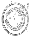
- Fig. 5a and 5b are not part of the invention.
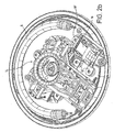
- Fig. 1a there may be seen an electric heater for a liquid heating vessel which embodies the present invention.
- the heater comprises a heater substrate 2 made of 300 series stainless steel 0.9 mm thick which has a thermal conductivity of 25 Wm -1 K -1 .
- Other grades of stainless steel may be used such as 400 series.
- a thickness in the range 0.5 to 0.9 mm is preferred.
- the edge of the heater substrate 2 is formed with a raised lip and downwardly depending channel to form a sealing fit with a plastics heating vessel. Further details of this arrangement may be found in WO 96/18331 .
- An aluminium heat distribution plate 4 is bonded onto the dry face of the heater substrate covering substantially the whole of this face.
- a sheathed heating element 6 having a nominal power rating of 2.2 kW is brazed onto the aluminium plate 4 around the periphery thereof as is well known in the art.
- Low resistance terminations 8 At either end of the heating element 6 are low resistance terminations 8 for making electrical connection to the heating element, better known as cold tails.
- the sump 10 is pre-formed by deep-drawing a flat stainless steel plate and is brazed onto a pre-formed aperture in the substrate in the same brazing operation as is used to attach the element 8.
- the substrate 2 could be deep drawn to form the sump 10.
- the sump 10 may be seen more clearly in the enlarged scrap section of Figure 1c. It will be seen that the sump is circular with an inside diameter of 11 mm and an inside depth of 12 mm. It may further be seen that a cut-away 4a is formed in the heat distribution plate around the sump 10. The cut-away 4a is sufficiently big that there is a gap of at least 6 mm between the heat distribution plate 4 and sump 10 all the way round.
- the substrate 2 is 0.9mm thick and has a thermal conductivity of 25 Wm -1 K -1 (Watts per metre per Kelvin).
- the heat distribution plate 4 is 2mm thick and has a conductivity of 210 Wm -1 K -1 .
- a series of mounting bosses 12 are formed on the heat distribution plate 4 for mounting a control unit and a steam switch module thereto.
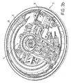
- FIG 1b is a view of the heater of Fig 1a with a control unit 14 and a steam switch 16 mounted to it.
- the control unit 14 is the applicant's commercially available U1830 control, the basic principles of which are described in WO 95/34187 to which further reference should be made for fuller details.
- the steam switch module 16 is the applicant's standard R48 steam switch module which incorporates a snap-acting bimetallic actuator (not visible) which acts on an over-centre switch mechanism to open a pair of electrical contacts.
- the steam switch module 16 is mounted with its bimetallic actuator in good thermal contact with the underside of the sump 10. It is mounted by means of a mounting bracket 18 which is bolted to two of the mounting bosses 12 formed on the heat distribution plate 4, sharing one of these with the control unit 14.
- the steam switch 16 is connected electrically in series between the line output of the control unit 16 (not shown) and one of the cold tails 8 of the heating element 6.
- a trip lever which is attached to a coupling point 16a of the steam switch and is able to operate in an upward direction (as viewed from Fig. 16) on a similar coupling point 14a on the U1830 trip lever.
- a liquid heating vessel fitted with the heater shown in Figures 1a and 1b is filled with water which of course means that the sump 10 becomes filled with water.
- the heater 6 When the heater 6 is energised, it will begin to heat the water in the vessel.
- the temperature of the liquid in the sump 10 will lag between the temperature of the water being heated in the vessel.
- the sump 10 since the sump 10 is located between the cold tails 8, i.e.
- the heater Assuming that the heater is installed in a vessel having a maximum capacity of 1.7 litres and that the vessel is filled to capacity with water initially at 20°C, the flow of energy into the sump directly from the heater may be estimated. Consequently the temperature rise of the liquid in the sump may be estimated. In the present example it has been calculated that approximately 190 Joules of energy will flow into the sump, meaning that the temperature of the water therein will rise to 60°C whilst the bulk of the liquid approaches boiling. This ensures that premature actuation of the bimetal will not occur.
- the temperature of the heat distribution plate 4 will rise rapidly until one or both of the bimetal actuators of the control unit 14 operates to trip the trip lever thereof, thereby interrupting the electrical supply to the heating element 6. Power may be restored by the user manually operating the same trip lever as is used to reset the steam switch 16.
- FIG 2a there may be seen a second embodiment of the invention.
- This embodiment in common with the first are denoted by like reference numerals.
- the difference between this embodiment and that shown in Figs. 1a and 1b is that in this embodiment the heating element 6 extends around only approximately 180° of the periphery of the heat distribution plate 4.
- the sump 10 is not located midway between the cold tails 8 but rather is closer to one of them. However, it is no closer to either cold tail 8 than in the previous embodiment.
- FIG. 2b shows the control unit 14 and steam switch 16 mounted to the heat distribution plate 4 and sump 10 respectively.
- the control unit 14 and steam switch 16 may now be oriented to be substantially parallel to one another, thereby facilitating the provision of a single operating lever protruding from the vessel in use.
- the steam switch 16 is not mounted on a separate bracket as in the previous embodiment, but rather it is mounted on an extension of the mounting bracket 18' of the control unit 14. Operation of this embodiment is exactly the same as the previous one and will not, therefore, be described again.
- FIGS 3a and 3b show a third embodiment of the invention.
- This embodiment is substantially similar to the first except that a second heating element 20 is provided inwardly of the first heating element 6.
- the nominal power rating of the first element 6 is 2400 watts, whilst that of the second element 20 is 200 watts.
- the two elements 6, 20 are connected electrically in parallel so that during normal heating operation their combined power output is 2600 watts.
- the steam switch 16 in this embodiment interrupts power only to the first element 6, thereby leaving the second element 20 energised. This means that upon boiling of water in the vessel, the water continues to be heated at a relatively low 200 watts in order to keep it warm.
- the control unit 14 however is connected electrically in series with both of the heating elements 6, 20 so that in the event the heater is switched on dry or boils dry, power to both elements 6, 20 will be interrupted.
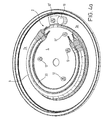
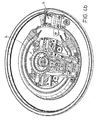
- Figs. 4a and 4b show a fourth embodiment of the invention. It will be seen in this embodiment that the substrate 2 extends beyond the heat distribution plate 4 thus forming an unheated rim 2a. It is in this unheated rim 2a that the sump 10 is provided. It will therefore be seen that the sump 10 is provided outside of the footprint of the heat distribution plate 4.
- the relatively poor thermal conductivity of the stainless steel substrate 2 ensures that there is relatively little direct heating of the sump 10 by the heating element 6, 20.
- convection of the bulk of the water in the vessel during normal heating will be confined generally to the area in the centre in the heater within the footprint of the heat distribution plate 4. It may be seen from Fig.
- Figs 5a and 5b show a fifth embodiment which is not part of the invention which differs from the fourth embodiment in that the sump 10 is no longer located in the vicinity of the cold tails 8, 22, but rather is mounted further round the element 6, 20 but still outside the footprint of the heat distribution plate 4.
- the electrical connection and operation of this embodiment is identical to that of the third and fourth embodiment.
- the invention is not restricted to use with heaters having a sheathed heating element bonded to a substrate.
- the heater may be a thick film heater.
Landscapes
- Engineering & Computer Science (AREA)
- Food Science & Technology (AREA)
- Cookers (AREA)
- Resistance Heating (AREA)
- Saccharide Compounds (AREA)
- Electric Stoves And Ranges (AREA)
- Heating, Cooling, Or Curing Plastics Or The Like In General (AREA)
- Mounting, Exchange, And Manufacturing Of Dies (AREA)
Claims (25)
- Elément chauffant électrique pour un récipient de chauffage de liquide comprenant un substrat généralement planaire (2), un élément de chauffage allongé (6) comprenant des terminaisons (8) à des extrémités respectives pour effectuer une connexion électrique à celles-ci, l'élément de chauffage (6) étant monté ou formé sur ledit substrat (2) afin que lesdites terminaisons (8) soient écartées sur le substrat (2), caractérisé en ce que l'élément chauffant comprend en outre un puits (10) ayant un volume relativement petit formé dans le substrat (2) entre lesdites terminaisons (8).
- Récipient de chauffage de liquide comprenant un élément chauffant électrique comprenant un substrat généralement planaire (2) et un élément cde chauffage allongé (6) comprenant des terminaisons (8) à des extrémités respectives pour faire une connexion électrique à celles-ci, monté ou formé sur ledit substrat (2) afin que lesdites terminaisons (8) soient écartées sur le substrat (2), caractérisé en ce que l'élément chauffant comprend en outre un puits (10) ayant un volume relativement petit comparé au récipient de chauffage de liquide dans son intégralité, formé dans le substrat (2) entre lesdites terminaisons (8).
- Elément chauffant ou récipient de chauffage de liquide selon la revendication 1 ou 2, dans lequel l'élément de chauffage (6) est adapté pour se prolonger selon un arc autour de l'élément chauffant.
- Elément chauffant ou récipient de chauffage de liquide selon la revendication 3, dans lequel toute la longueur de l'élément (6) est agencée selon un arc.
- Elément chauffant ou récipient de chauffage de liquide selon la revendication 3 ou 4, dans lequel ledit élément (6) est agencé substantiellement à la périphérie de l'élément chauffant.
- Elément chauffant ou récipient de chauffage de liquide selon l'une quelconque des revendications 3 à 5, dans lequel l'élément de chauffage (6) s'étend autour d'environ 180° de la périphérie de l'élément chauffant.
- Elément chauffant ou récipient de chauffage de liquide selon la revendication 6, dans lequel le puits (10) est prévu sur substantiellement le même arc que l'élément de chauffage (6).
- Elément chauffant ou récipient de chauffage de liquide selon l'une quelconque des revendications précédentes, dans lequel le puits (10) est localisé à égale distance entre les deux terminaisons (8).
- Elément chauffant ou récipient de chauffage de liquide selon l'une quelconque des revendications précédentes, comprenant un actionneur mécanique pour détecter quand la température du puits (10) augmente du fait d'une ébullition.
- Elément chauffant ou récipient de chauffage de liquide selon la revendication 9, dans lequel ledit actionneur comprend un actionneur bimétallique, de préférence un actionneur bimétallique à action instantanée.
- Elément chauffant ou récipient de chauffage de liquide selon la revendication 10, dans lequel l'actionneur bimétallique à action instantanée est fourni par un module de commutation de vapeur normalisé (16).
- Elément chauffant ou récipient de chauffage de liquide selon la revendication 11, comprenant une unité de commande (14), dans lequel ledit module de commutation de vapeur (16) est monté sur une plaque de montage commune avec ladite unité de commande (14).
- Elément chauffant ou récipient de chauffage de liquide selon l'une quelconque des revendications 9 à 12, dans lequel l'actionneur est adapté pour ouvrir un jeu de contacts électriques quand l'ébullition du liquide dans le récipient est détectée.
- Elément chauffant ou récipient de chauffage de liquide selon la revendication 13, dans lequel lesdits contacts sont agencés en série avec l'alimentation électrique de l'élément de chauffage (6) afin que l'alimentation électrique soit interrompue lors de l'ébullition pour couper l'alimentation de l'élément chauffant.
- Elément chauffant ou récipient de chauffage de liquide selon la revendication 13 ou 14, dans lequel lesdits contacts font partie d'un ensemble pour alimenter, ou maintenir alimenté uniquement, un élément de maintien d'ébullition ou de chaleur (20) une fois que le liquide dans le récipient est entré en ébullition.
- Elément chauffant ou récipient de chauffage de liquide selon la revendication 13, 14 ou 15, dans lequel l'actionneur est agencé pour déplacer un mécanisme décentré qui maintient la réduction ou l'interruption d'alimentation de l'élément de chauffage (6) jusqu'au moment où il est remis à la position initiale par l'utilisateur.
- Elément chauffant ou récipient de chauffage de liquide selon la revendication 16, comprenant un levier de remise à la position initiale pour permettre à un utilisateur de remettre à la position initiale le mécanisme décentré.
- Elément chauffant ou récipient de chauffage de liquide selon la revendication 17, dans lequel le levier de remise à la position initiale est relié à un levier de déplacement d'une unité de commande afin que le levier de remise à la position initiale puisse remettre correctement à zéro à la fois le commutateur de vapeur (16) et l'unité de commande (14) s'il faut que l'un ou l'autre fonctionne.
- Elément chauffant ou récipient de chauffage de liquide selon l'une quelconque des revendications précédentes, comprenant une plaque de distribution de chaleur thermiquement conductrice (4) entre l'élément de chauffage (6) et le substrat (2).
- Elément chauffant ou récipient de chauffage de liquide selon la revendication 19, comprenant une découpe (4a) dans la plaque de distribution de chaleur (4).
- Elément chauffant ou récipient de chauffage de liquide selon la revendication 20, dans lequel le bord de la plaque de distribution de chaleur (4) est à au moins 6 mm du puits (10).
- Elément chauffant ou récipient de chauffage de liquide selon l'une quelconque des revendications 19 à 21, dans lequel l'élément de chauffage (6) est agencé autour de la périphérie de la plaque de distribution de chaleur (4).
- Elément chauffant ou récipient de chauffage de liquide selon l'une quelconque des revendications précédentes, dans lequel ledit puits (10) comprend au moins une paroi latérale qui est plus mince que ledit substrat.
- Elément chauffant ou récipient de chauffage de liquide selon l'une quelconque des revendications précédentes, dans lequel ledit puits (10) a une profondeur qui est au moins aussi grande ou plus grande que son diamètre.
- Elément chauffant ou récipient de chauffage de liquide selon l'une quelconque des revendications précédentes, dans lequel les parois dudit puits (10) sont inclinées à un angle d'au moins 45°, plus préférentiellement d'au moins 75° et plus préférentiellement d'environ 90°, en d'autres termes sont verticales.
Applications Claiming Priority (3)
| Application Number | Priority Date | Filing Date | Title |
|---|---|---|---|
| GB0109950A GB2377608B (en) | 2001-04-23 | 2001-04-23 | Electric heaters |
| GB0109950 | 2001-04-23 | ||
| PCT/GB2002/001886 WO2002085169A2 (fr) | 2001-04-23 | 2002-04-22 | Radiateurs electriques |
Publications (2)
| Publication Number | Publication Date |
|---|---|
| EP1381299A2 EP1381299A2 (fr) | 2004-01-21 |
| EP1381299B1 true EP1381299B1 (fr) | 2007-06-13 |
Family
ID=9913297
Family Applications (1)
| Application Number | Title | Priority Date | Filing Date |
|---|---|---|---|
| EP02716951A Revoked EP1381299B1 (fr) | 2001-04-23 | 2002-04-22 | Radiateurs electriques |
Country Status (8)
| Country | Link |
|---|---|
| EP (1) | EP1381299B1 (fr) |
| CN (1) | CN1461196A (fr) |
| AT (1) | ATE364341T1 (fr) |
| AU (1) | AU2002247870A1 (fr) |
| DE (1) | DE60220659T2 (fr) |
| ES (1) | ES2289092T3 (fr) |
| GB (1) | GB2377608B (fr) |
| WO (1) | WO2002085169A2 (fr) |
Families Citing this family (9)
| Publication number | Priority date | Publication date | Assignee | Title |
|---|---|---|---|---|
| GB2399735B (en) | 2003-03-25 | 2006-04-26 | Strix Ltd | Electric liquid boiling appliances |
| GB0406428D0 (en) * | 2004-03-22 | 2004-04-21 | Strix Ltd | Heaters for liquid heating vessels |
| GB0421524D0 (en) | 2004-09-28 | 2004-10-27 | Strix Ltd | Electric liquid boiling appliances |
| GB0518338D0 (en) * | 2005-09-09 | 2005-10-19 | Strix Ltd | Heaters for liquid heating vessels |
| GB0519594D0 (en) * | 2005-09-26 | 2005-11-02 | Strix Ltd | Heaters for liquid heating vessels |
| ITVE20060001U1 (it) * | 2006-01-12 | 2007-07-13 | I R C A S P A Ind Resistenze Corazzate ... | Contenitore per fluidi da riscaldare |
| AU2013200269B2 (en) * | 2006-05-12 | 2015-09-03 | Newell Australia Pty Ltd | Improved temperature sensor for an electric heating vessel |
| GB2477944B (en) * | 2010-02-18 | 2015-04-01 | Otter Controls Ltd | Cordless electrical appliances |
| CN113520156B (zh) * | 2020-04-14 | 2022-08-30 | 广东美的生活电器制造有限公司 | 液体加热装置 |
Family Cites Families (6)
| Publication number | Priority date | Publication date | Assignee | Title |
|---|---|---|---|---|
| US2857502A (en) * | 1954-06-01 | 1958-10-21 | Dormeyer Corp | Beverage maker |
| IN192511B (fr) | 1994-06-09 | 2004-04-24 | Strix Ltd | |
| AU4183696A (en) | 1994-12-13 | 1996-07-03 | Strix Limited | Liquid heating vessels |
| US6153859A (en) * | 1995-07-31 | 2000-11-28 | Strix Limited | Liquid heating vessels |
| GB2322274B (en) * | 1997-02-17 | 1999-01-13 | Strix Ltd | Controls for electric heaters |
| GB2346738B (en) * | 1999-02-11 | 2003-01-29 | Otter Controls Ltd | Improvements relating to control of electric heating elements |
-
2001
- 2001-04-23 GB GB0109950A patent/GB2377608B/en not_active Expired - Fee Related
-
2002
- 2002-04-22 EP EP02716951A patent/EP1381299B1/fr not_active Revoked
- 2002-04-22 AU AU2002247870A patent/AU2002247870A1/en not_active Abandoned
- 2002-04-22 WO PCT/GB2002/001886 patent/WO2002085169A2/fr active IP Right Grant
- 2002-04-22 AT AT02716951T patent/ATE364341T1/de not_active IP Right Cessation
- 2002-04-22 DE DE60220659T patent/DE60220659T2/de not_active Expired - Fee Related
- 2002-04-22 CN CN02801305.0A patent/CN1461196A/zh active Pending
- 2002-04-22 ES ES02716951T patent/ES2289092T3/es not_active Expired - Lifetime
Also Published As
| Publication number | Publication date |
|---|---|
| GB0109950D0 (en) | 2001-06-13 |
| CN1461196A (zh) | 2003-12-10 |
| ATE364341T1 (de) | 2007-07-15 |
| EP1381299A2 (fr) | 2004-01-21 |
| AU2002247870A1 (en) | 2002-11-05 |
| GB2377608B (en) | 2005-09-07 |
| DE60220659T2 (de) | 2007-10-25 |
| WO2002085169A2 (fr) | 2002-10-31 |
| WO2002085169A3 (fr) | 2003-01-23 |
| DE60220659D1 (de) | 2007-07-26 |
| GB2377608A (en) | 2003-01-15 |
| ES2289092T3 (es) | 2008-02-01 |
Similar Documents
| Publication | Publication Date | Title |
|---|---|---|
| US5793929A (en) | Immersion heaters with heating elements in the form of printed circuit tracks | |
| EP0734215B1 (fr) | Appareil pour chauffer des liquides | |
| RU2138136C1 (ru) | Электронагреваемый сосуд для кипячения воды | |
| EP1381299B1 (fr) | Radiateurs electriques | |
| WO1999002080A1 (fr) | Receptacles chauffant des liquides et dispositifs de reglage adaptes | |
| EP0630551B1 (fr) | Perfectionnements apportes a des elements de chauffage electriques a immersion et commandes associees | |
| EP1762161B1 (fr) | Bouilloire | |
| CN100475103C (zh) | 多功率加热器 | |
| EP1462039B1 (fr) | Appareil électrique pour porter à ébullition des liquides | |
| GB2052226A (en) | Improvements In or Relating To Electric Kettles | |
| GB2052227A (en) | Improvements in Electric Immersion Heaters | |
| WO1997043873A1 (fr) | Dispositifs de chauffage electriques | |
| GB2265071A (en) | Thermal path to a thermal cut out/ boiling sensor for an electric immmersion heating element | |
| GB2412555A (en) | Disposition of sheathed heating elements on a liquid heater base | |
| EP1639921B1 (fr) | Bouilloire électrique | |
| WO1996019909A1 (fr) | Elements chauffants electriques | |
| GB2379851A (en) | Improved protection against failure of planar heating elements | |
| GB2305341A (en) | Mounting immersion heaters to control devices | |
| GB2348589A (en) | Die-cast heater having a boss providing a contact location for bimetallic actuator | |
| JPS6319069B2 (fr) | ||
| GB2260070A (en) | Immersion element hot return mechanically mounted on head plate | |
| GB2220547A (en) | Electric immersion heaters | |
| GB2306284A (en) | Electric heating elements | |
| WO2014096768A1 (fr) | Réchauffeurs de liquide |
Legal Events
| Date | Code | Title | Description |
|---|---|---|---|
| PUAI | Public reference made under article 153(3) epc to a published international application that has entered the european phase |
Free format text: ORIGINAL CODE: 0009012 |
|
| 17P | Request for examination filed |
Effective date: 20031006 |
|
| AK | Designated contracting states |
Kind code of ref document: A2 Designated state(s): AT BE CH CY DE DK ES FI FR GB GR IE IT LI LU MC NL PT SE TR |
|
| AX | Request for extension of the european patent |
Extension state: AL LT LV MK RO SI |
|
| 111Z | Information provided on other rights and legal means of execution |
Free format text: ATBECHCYDEDKESFIFRGBGRIEITLUMCNLPTSETR Effective date: 20050822 |
|
| GRAP | Despatch of communication of intention to grant a patent |
Free format text: ORIGINAL CODE: EPIDOSNIGR1 |
|
| GRAS | Grant fee paid |
Free format text: ORIGINAL CODE: EPIDOSNIGR3 |
|
| GRAA | (expected) grant |
Free format text: ORIGINAL CODE: 0009210 |
|
| AK | Designated contracting states |
Kind code of ref document: B1 Designated state(s): AT BE CH CY DE DK ES FI FR GB GR IE IT LI LU MC NL PT SE TR |
|
| PG25 | Lapsed in a contracting state [announced via postgrant information from national office to epo] |
Ref country code: CH Free format text: LAPSE BECAUSE OF FAILURE TO SUBMIT A TRANSLATION OF THE DESCRIPTION OR TO PAY THE FEE WITHIN THE PRESCRIBED TIME-LIMIT Effective date: 20070613 Ref country code: LI Free format text: LAPSE BECAUSE OF FAILURE TO SUBMIT A TRANSLATION OF THE DESCRIPTION OR TO PAY THE FEE WITHIN THE PRESCRIBED TIME-LIMIT Effective date: 20070613 |
|
| REG | Reference to a national code |
Ref country code: GB Ref legal event code: FG4D |
|
| REG | Reference to a national code |
Ref country code: CH Ref legal event code: EP |
|
| REG | Reference to a national code |
Ref country code: IE Ref legal event code: FG4D |
|
| REF | Corresponds to: |
Ref document number: 60220659 Country of ref document: DE Date of ref document: 20070726 Kind code of ref document: P |
|
| PG25 | Lapsed in a contracting state [announced via postgrant information from national office to epo] |
Ref country code: SE Free format text: LAPSE BECAUSE OF FAILURE TO SUBMIT A TRANSLATION OF THE DESCRIPTION OR TO PAY THE FEE WITHIN THE PRESCRIBED TIME-LIMIT Effective date: 20070913 |
|
| ET | Fr: translation filed | ||
| PG25 | Lapsed in a contracting state [announced via postgrant information from national office to epo] |
Ref country code: AT Free format text: LAPSE BECAUSE OF FAILURE TO SUBMIT A TRANSLATION OF THE DESCRIPTION OR TO PAY THE FEE WITHIN THE PRESCRIBED TIME-LIMIT Effective date: 20070613 |
|
| REG | Reference to a national code |
Ref country code: CH Ref legal event code: PL |
|
| PG25 | Lapsed in a contracting state [announced via postgrant information from national office to epo] |
Ref country code: BE Free format text: LAPSE BECAUSE OF FAILURE TO SUBMIT A TRANSLATION OF THE DESCRIPTION OR TO PAY THE FEE WITHIN THE PRESCRIBED TIME-LIMIT Effective date: 20070613 |
|
| PG25 | Lapsed in a contracting state [announced via postgrant information from national office to epo] |
Ref country code: PT Free format text: LAPSE BECAUSE OF FAILURE TO SUBMIT A TRANSLATION OF THE DESCRIPTION OR TO PAY THE FEE WITHIN THE PRESCRIBED TIME-LIMIT Effective date: 20071113 |
|
| REG | Reference to a national code |
Ref country code: ES Ref legal event code: FG2A Ref document number: 2289092 Country of ref document: ES Kind code of ref document: T3 |
|
| PLBI | Opposition filed |
Free format text: ORIGINAL CODE: 0009260 |
|
| 26 | Opposition filed |
Opponent name: AEG HAUSGERAETE GMBH Effective date: 20080228 |
|
| PLAX | Notice of opposition and request to file observation + time limit sent |
Free format text: ORIGINAL CODE: EPIDOSNOBS2 |
|
| PG25 | Lapsed in a contracting state [announced via postgrant information from national office to epo] |
Ref country code: GR Free format text: LAPSE BECAUSE OF FAILURE TO SUBMIT A TRANSLATION OF THE DESCRIPTION OR TO PAY THE FEE WITHIN THE PRESCRIBED TIME-LIMIT Effective date: 20070914 Ref country code: DK Free format text: LAPSE BECAUSE OF FAILURE TO SUBMIT A TRANSLATION OF THE DESCRIPTION OR TO PAY THE FEE WITHIN THE PRESCRIBED TIME-LIMIT Effective date: 20070613 |
|
| NLR1 | Nl: opposition has been filed with the epo |
Opponent name: AEG HAUSGERAETE GMBH |
|
| PGFP | Annual fee paid to national office [announced via postgrant information from national office to epo] |
Ref country code: DE Payment date: 20080429 Year of fee payment: 7 Ref country code: ES Payment date: 20080528 Year of fee payment: 7 |
|
| PLAF | Information modified related to communication of a notice of opposition and request to file observations + time limit |
Free format text: ORIGINAL CODE: EPIDOSCOBS2 |
|
| PGFP | Annual fee paid to national office [announced via postgrant information from national office to epo] |
Ref country code: IT Payment date: 20080422 Year of fee payment: 7 |
|
| PLAF | Information modified related to communication of a notice of opposition and request to file observations + time limit |
Free format text: ORIGINAL CODE: EPIDOSCOBS2 |
|
| PGFP | Annual fee paid to national office [announced via postgrant information from national office to epo] |
Ref country code: NL Payment date: 20080430 Year of fee payment: 7 |
|
| PLAF | Information modified related to communication of a notice of opposition and request to file observations + time limit |
Free format text: ORIGINAL CODE: EPIDOSCOBS2 |
|
| PG25 | Lapsed in a contracting state [announced via postgrant information from national office to epo] |
Ref country code: MC Free format text: LAPSE BECAUSE OF NON-PAYMENT OF DUE FEES Effective date: 20080430 |
|
| PGFP | Annual fee paid to national office [announced via postgrant information from national office to epo] |
Ref country code: FR Payment date: 20080409 Year of fee payment: 7 |
|
| PGFP | Annual fee paid to national office [announced via postgrant information from national office to epo] |
Ref country code: GB Payment date: 20080415 Year of fee payment: 7 |
|
| PLBB | Reply of patent proprietor to notice(s) of opposition received |
Free format text: ORIGINAL CODE: EPIDOSNOBS3 |
|
| PG25 | Lapsed in a contracting state [announced via postgrant information from national office to epo] |
Ref country code: FI Free format text: LAPSE BECAUSE OF FAILURE TO SUBMIT A TRANSLATION OF THE DESCRIPTION OR TO PAY THE FEE WITHIN THE PRESCRIBED TIME-LIMIT Effective date: 20070613 |
|
| PG25 | Lapsed in a contracting state [announced via postgrant information from national office to epo] |
Ref country code: IE Free format text: LAPSE BECAUSE OF NON-PAYMENT OF DUE FEES Effective date: 20080422 |
|
| PG25 | Lapsed in a contracting state [announced via postgrant information from national office to epo] |
Ref country code: CY Free format text: LAPSE BECAUSE OF FAILURE TO SUBMIT A TRANSLATION OF THE DESCRIPTION OR TO PAY THE FEE WITHIN THE PRESCRIBED TIME-LIMIT Effective date: 20070613 |
|
| GBPC | Gb: european patent ceased through non-payment of renewal fee |
Effective date: 20090422 |
|
| NLV4 | Nl: lapsed or anulled due to non-payment of the annual fee |
Effective date: 20091101 |
|
| REG | Reference to a national code |
Ref country code: FR Ref legal event code: ST Effective date: 20091231 |
|
| PG25 | Lapsed in a contracting state [announced via postgrant information from national office to epo] |
Ref country code: DE Free format text: LAPSE BECAUSE OF NON-PAYMENT OF DUE FEES Effective date: 20091103 |
|
| RDAE | Information deleted related to despatch of communication that patent is revoked |
Free format text: ORIGINAL CODE: EPIDOSDREV1 |
|
| RDAF | Communication despatched that patent is revoked |
Free format text: ORIGINAL CODE: EPIDOSNREV1 |
|
| PG25 | Lapsed in a contracting state [announced via postgrant information from national office to epo] |
Ref country code: NL Free format text: LAPSE BECAUSE OF NON-PAYMENT OF DUE FEES Effective date: 20091101 |
|
| PG25 | Lapsed in a contracting state [announced via postgrant information from national office to epo] |
Ref country code: FR Free format text: LAPSE BECAUSE OF NON-PAYMENT OF DUE FEES Effective date: 20091222 Ref country code: GB Free format text: LAPSE BECAUSE OF NON-PAYMENT OF DUE FEES Effective date: 20090422 |
|
| RDAG | Patent revoked |
Free format text: ORIGINAL CODE: 0009271 |
|
| STAA | Information on the status of an ep patent application or granted ep patent |
Free format text: STATUS: PATENT REVOKED |
|
| 27W | Patent revoked |
Effective date: 20100219 |
|
| REG | Reference to a national code |
Ref country code: ES Ref legal event code: FD2A Effective date: 20090423 |
|
| PG25 | Lapsed in a contracting state [announced via postgrant information from national office to epo] |
Ref country code: LU Free format text: LAPSE BECAUSE OF NON-PAYMENT OF DUE FEES Effective date: 20080422 |
|
| PG25 | Lapsed in a contracting state [announced via postgrant information from national office to epo] |
Ref country code: TR Free format text: LAPSE BECAUSE OF FAILURE TO SUBMIT A TRANSLATION OF THE DESCRIPTION OR TO PAY THE FEE WITHIN THE PRESCRIBED TIME-LIMIT Effective date: 20070613 |
|
| PG25 | Lapsed in a contracting state [announced via postgrant information from national office to epo] |
Ref country code: IT Free format text: LAPSE BECAUSE OF NON-PAYMENT OF DUE FEES Effective date: 20090422 |
|
| PG25 | Lapsed in a contracting state [announced via postgrant information from national office to epo] |
Ref country code: ES Free format text: LAPSE BECAUSE OF NON-PAYMENT OF DUE FEES Effective date: 20090423 |