EP1381135A1 - Battery-driven electronic device and mobile communication apparatus - Google Patents
Battery-driven electronic device and mobile communication apparatus Download PDFInfo
- Publication number
- EP1381135A1 EP1381135A1 EP02720447A EP02720447A EP1381135A1 EP 1381135 A1 EP1381135 A1 EP 1381135A1 EP 02720447 A EP02720447 A EP 02720447A EP 02720447 A EP02720447 A EP 02720447A EP 1381135 A1 EP1381135 A1 EP 1381135A1
- Authority
- EP
- European Patent Office
- Prior art keywords
- battery
- voltage
- switching means
- whose
- load
- Prior art date
- Legal status (The legal status is an assumption and is not a legal conclusion. Google has not performed a legal analysis and makes no representation as to the accuracy of the status listed.)
- Withdrawn
Links
Images







Classifications
-
- H—ELECTRICITY
- H02—GENERATION; CONVERSION OR DISTRIBUTION OF ELECTRIC POWER
- H02M—APPARATUS FOR CONVERSION BETWEEN AC AND AC, BETWEEN AC AND DC, OR BETWEEN DC AND DC, AND FOR USE WITH MAINS OR SIMILAR POWER SUPPLY SYSTEMS; CONVERSION OF DC OR AC INPUT POWER INTO SURGE OUTPUT POWER; CONTROL OR REGULATION THEREOF
- H02M3/00—Conversion of DC power input into DC power output
- H02M3/02—Conversion of DC power input into DC power output without intermediate conversion into AC
- H02M3/04—Conversion of DC power input into DC power output without intermediate conversion into AC by static converters
- H02M3/10—Conversion of DC power input into DC power output without intermediate conversion into AC by static converters using discharge tubes with control electrode or semiconductor devices with control electrode
- H02M3/145—Conversion of DC power input into DC power output without intermediate conversion into AC by static converters using discharge tubes with control electrode or semiconductor devices with control electrode using devices of a triode or transistor type requiring continuous application of a control signal
- H02M3/155—Conversion of DC power input into DC power output without intermediate conversion into AC by static converters using discharge tubes with control electrode or semiconductor devices with control electrode using devices of a triode or transistor type requiring continuous application of a control signal using semiconductor devices only
-
- H—ELECTRICITY
- H02—GENERATION; CONVERSION OR DISTRIBUTION OF ELECTRIC POWER
- H02J—ELECTRIC POWER NETWORKS; CIRCUIT ARRANGEMENTS OR SYSTEMS FOR SUPPLYING OR DISTRIBUTING ELECTRIC POWER; SYSTEMS FOR STORING ELECTRIC ENERGY
- H02J2207/00—Details of circuit arrangements for charging or discharging batteries or supplying loads from batteries
- H02J2207/20—Charging or discharging characterised by the power electronics converter
-
- H—ELECTRICITY
- H02—GENERATION; CONVERSION OR DISTRIBUTION OF ELECTRIC POWER
- H02M—APPARATUS FOR CONVERSION BETWEEN AC AND AC, BETWEEN AC AND DC, OR BETWEEN DC AND DC, AND FOR USE WITH MAINS OR SIMILAR POWER SUPPLY SYSTEMS; CONVERSION OF DC OR AC INPUT POWER INTO SURGE OUTPUT POWER; CONTROL OR REGULATION THEREOF
- H02M3/00—Conversion of DC power input into DC power output
- H02M3/02—Conversion of DC power input into DC power output without intermediate conversion into AC
- H02M3/04—Conversion of DC power input into DC power output without intermediate conversion into AC by static converters
- H02M3/10—Conversion of DC power input into DC power output without intermediate conversion into AC by static converters using discharge tubes with control electrode or semiconductor devices with control electrode
- H02M3/145—Conversion of DC power input into DC power output without intermediate conversion into AC by static converters using discharge tubes with control electrode or semiconductor devices with control electrode using devices of a triode or transistor type requiring continuous application of a control signal
- H02M3/155—Conversion of DC power input into DC power output without intermediate conversion into AC by static converters using discharge tubes with control electrode or semiconductor devices with control electrode using devices of a triode or transistor type requiring continuous application of a control signal using semiconductor devices only
- H02M3/156—Conversion of DC power input into DC power output without intermediate conversion into AC by static converters using discharge tubes with control electrode or semiconductor devices with control electrode using devices of a triode or transistor type requiring continuous application of a control signal using semiconductor devices only with automatic control of output voltage or current, e.g. switching regulators
- H02M3/158—Conversion of DC power input into DC power output without intermediate conversion into AC by static converters using discharge tubes with control electrode or semiconductor devices with control electrode using devices of a triode or transistor type requiring continuous application of a control signal using semiconductor devices only with automatic control of output voltage or current, e.g. switching regulators including plural semiconductor devices as final control devices for a single load
- H02M3/1582—Buck-boost converters
Definitions
- the present invention relates to a battery-driven electronic device employing a battery as its input source and mobile communications equipment such as portable telephones and portable communications terminals in which such a battery-driven electronics device is mounted.
- a conventional battery-driven electronic device uses as its input source a battery typified by a conventional lithium ion battery, more specifically, a battery 401 employing lithium cobaltate as the positive electrode, graphite as the negative electrode, and a nonaqueous solvent containing lithium supporting electrolyte as the electrolyte and having an average battery voltage of 3.7 V at room temperature as the discharge characteristics, and supplies a predetermined voltage Eo to a load 406 via a step-down converter constituted by switching means 402, rectification switching means 403, an inductor 404, and an output capacitor 405.
- a step-down converter constituted by switching means 402, rectification switching means 403, an inductor 404, and an output capacitor 405.
- An “average battery voltage” is defined as a voltage obtained by dividing the time integration of the battery voltage when discharge is performed at a rated current from the rated charge state to the rated discharge capacity by the discharge time.
- a “rated charge end voltage” is defined as a battery voltage at the end of a charge operation necessary to obtain the rated discharge capacity.
- a “rated discharge end voltage” is defined as a battery voltage when the rated discharge capacity is obtained.
- a “rated discharge last stage voltage” is defined as a battery voltage when a large change occurs in the slope of the discharge voltage characteristics during discharging at the rated current.
- the switching means 402 when the switching means 402 is turned off, the voltage of the inductor 404 is inverted, and the rectification switching means 403 is turned on, and thus the supply voltage Eo is applied to the inductor 404.
- the current in the inductor 404 flows through the rectification switching means 403 to the output capacitor 405. This current is decreased, and the magnetic energy accumulated in the inductor 404 is released. This period is taken as Toff.
- the supply voltage Eo to the load 406 can be adjusted under the limitation of Ei > Eo with respect to variations of the battery voltage Ei by the on/off control of the switching means 402.
- a step-up converter is used instead of the step-down converter.
- the configuration using a step-up converter is disclosed, for example, in JP 4-315320 A.
- the conventional lithium ion battery as the battery 401 is characterized in that the discharge characteristics are flat, that is, a reduction in a battery voltage associated with discharge is small (the battery voltage change ratio is small).
- the battery voltage can be close to the voltage that is required to be supplied to the load 406, and the loss in the step-down converter can be decreased.
- this relationship does not change with discharging, so that the energy of the battery can be used efficiently.
- the battery voltage Ei should be higher than the voltage Eo that is required to be supplied to the load. On the other hand, it is better that the battery voltage Ei is close to the supply voltage Eo in order to operate the step-down converter efficiently.
- the battery voltage Ei should be lower than the voltage Eo that is required to be supplied to the load. In this case as well as in the case of the step-down converter, it is better that the battery voltage Ei is close to the supply voltage Eo in order to operate the step-up converter efficiently.
- the characteristics required for batteries are that the battery voltage Ei is slightly higher or slightly lower than the supply voltage Eo and that the discharge characteristics are flat.
- the battery use time which is a period until the battery voltage that decreases with discharging reaches the lower limit of the voltage at which the battery can be used, has been prolonged by achieving a large capacity with the weight and volume unchanged.
- the conventional lithium ion battery employing lithium cobaltate as the positive electrode, graphite as the negative electrode, and a nonaqueous solvent containing lithium supporting electrolyte as the electrolyte and having an average battery voltage of 3.7 V at room temperature has the most excellent discharge characteristics at present.
- the lithium ion battery employing such a new material is incorporated into equipment in which the conventional lithium ion battery is used, and the supply voltage required by the load in the electronic device is between the rated charge end voltage and the rated discharge end voltage of the battery, then the following problem arises.
- the battery voltage is decreased with discharging, and thus the time at which the battery voltage becomes lower than the supply voltage required by the load is reached earlier than the conventional lithium ion battery, so that the advantage of the high energy density resulted from the new material cannot be utilized. Consequently, the use time of the equipment is shorter than that of the conventional lithium ion battery.
- two cells each of which is a lithium ion battery made of a new material having a low average battery voltage and a large battery voltage change ratio, are used to increase the battery voltage and are combined with a step-down converter.
- the voltage difference between the input and the output becomes large, so that it is difficult to realize high efficiency of the step-down converter, and the input voltage is increased. Therefore, it is necessary to increase the withstand voltage of capacitors or semiconductors, and therefore the efficiency is further decreased and the components become larger so that compactness cannot be achieved.
- the present invention is carried out, based on the fact that the energy of a battery can be utilized effectively by combining a lithium ion battery made of a new material and a step-up and -down converter, in order to solve the problem that since a lithium ion battery made of a new material that can improve the energy density of a battery has a low average battery voltage and a large battery voltage change ratio, high capacity energy cannot fully be utilized when this battery is used in a battery-driven electronic device.
- a first battery-driven electronic device of the present invention includes a battery having discharge characteristics that a battery voltage change ratio, which is a value obtained by dividing a voltage difference (Ec-Ed) by Ec, where Ec is an open circuit voltage after a rated charge end voltage is reached, and Ed is an open circuit voltage after a rated discharge end voltage is reached, is 0.25 or more; a step-up and -down converter that has an output voltage of the battery as an input source, performs at least a step-down operation mode and a step-up operation mode in accordance with the output voltage of the battery, and outputs a predetermined voltage; and a load to which the output voltage of the step-up and -down converter is supplied.
- a battery voltage change ratio which is a value obtained by dividing a voltage difference (Ec-Ed) by Ec, where Ec is an open circuit voltage after a rated charge end voltage is reached, and Ed is an open circuit voltage after a rated discharge end voltage is reached, is 0.25 or more
- a step-up and -down converter operates as follows.
- the voltage is set to a predetermined supply voltage by the step-down operation mode.
- the voltage is set to the predetermined supply voltage by the step-up operation mode.
- a second battery-driven electronic device of the present invention includes a battery having discharge characteristics that a battery voltage change ratio, which is a value obtained by dividing a voltage difference (Ec-Ed) by Ec, where Ec is an open circuit voltage after a rated charge end voltage is reached, and Ed is an open circuit voltage after a rated discharge end voltage is reached, is 0.25 or more; a step-up and -down converter that has an output voltage of the battery as an input source, performs a step-up and -down operation mode in accordance with the output voltage of the battery, and outputs a predetermined voltage; and a load to which the output voltage of the step-up and -down converter is supplied.
- a battery voltage change ratio which is a value obtained by dividing a voltage difference (Ec-Ed) by Ec, where Ec is an open circuit voltage after a rated charge end voltage is reached, and Ed is an open circuit voltage after a rated discharge end voltage is reached, is 0.25 or more
- a step-up and -down converter
- a step-up and -down converter sets the output voltage of the battery to the supply voltage required by the load by the step-up and - down operation mode.
- the battery is a prismatic battery, and the energy density per unit volume of the prismatic battery is 460 Wh/1 or more.
- the battery is cylindrical battery, and the energy density per unit volume of the cylindrical battery is 530 Wh/1 or more.
- a voltage required to be supplied to the load is within a range of the rated charge end voltage and a rated discharge last stage voltage of the battery. In this case, it is preferable that the difference between an average battery voltage associated with discharge characteristics of the battery and the supply voltage to the load is within a predetermined range.
- the loss in the step-up and -down converter can be reduced, and the use time of the battery can be prolonged further.
- the voltage required to be supplied to the load has a predetermined variation range, and the entire variation range of the supply voltage or a part thereof matches the entire range of the rated charge end voltage and the rated discharge last stage voltage of the battery or a part thereof.
- the voltage required to be supplied to the load has a predetermined variation range, a probability distribution of the required supply voltage in the predetermined variation range has one peak value, and a difference between the required supply voltage at the peak of the probability distribution and an average battery voltage associated with discharge characteristics of the battery is within a predetermined range.
- the loss in the step-up and -down converter can be reduced, and the use time of the battery can be prolonged further.
- the load comprises a power amplifier for wireless transmission, and such a battery-driven electronic device is mounted in mobile communications equipment.
- the step-up and - down converter has a function to fix an active component interposed between its input and its output to be on, because the loss in the step-up and -down converter can be reduced further, and the use time of the battery can be prolonged further.
- a step-up and -down converter having a first configuration includes first switching means whose one end is connected to one end of the battery; first rectification switching means whose one end is connected to the other end of the first switching means, and whose other end is connected to the other end of the battery; an inductor whose one end is connected to the other end of the first switching means; second switching means whose one end is connected to the other end of the inductor, and whose other end is connected to the other end of the battery; second rectification switching means whose one end is connected to one end of the second switching means, and whose other end is connected to one end of the load; an output capacitor whose one end is connected to one end of the load, and whose other end is connected to the other end of the battery and the other end of the load and that supplies a voltage to the load; a detecting circuit that detects the supply voltage at the output capacitor, outputs an error signal between the detected supply voltage and a first preset value (Eoh) for performing the step-down operation mode
- the detecting circuit includes a series circuit of a first detection resistor, a second detection resistor and a third detection resistor, to which the supply voltage is applied; a reference voltage source that outputs a reference voltage; a first error amplifier to which a potential at a connection point between the first detection resistor and the second detection resistor and the reference voltage are input, and outputs the first control signal; and a second error amplifier to which a potential at a connection point between the second detection resistor and the third detection resistor and the reference voltage are input, and outputs the second control signal.
- the step-up and -down converter having the first configuration first operates as a step-down converter to adjust the supply voltage to the first preset value when the output voltage Ei of the battery is higher than the first preset value Eoh. Then, when the output voltage Ei of the battery is decreased and becomes below the first preset value Eoh (higher than the second preset value Eol), the step-up and -down converter stops either the step-down operation or the step-up operation and operates in the through mode. When the output voltage Ei of the battery is decreased further and becomes below the second preset value Eol, the step-up and -down converter operates as a step-up converter to adjust the supply voltage to the second preset value.
- the step-up and - down converter has a function to short-circuit some or all components interposed between its input and its output, because the loss in the step-up and -down converter can be reduced further, and the use time of the battery can be prolonged further.
- a step-up and -down converter having a second configuration includes first switching means whose one end is connected to one end of the battery; first rectification switching means whose one end is connected to the other end of the first switching means, and whose other end is connected to the other end of the battery; an inductor whose one end is connected to the other end of the first switching means; second switching means whose one end is connected to the other end of the inductor, and whose other end is connected to the other end of the battery; third switching means whose one end is connected to one end of the first switching means, and whose other end is connected to the other end of the inductor; second rectification switching means whose one end is connected to one end of the second switching means, and whose other end is connected to one end of the load; an output capacitor whose one end is connected to one end of the load, and whose other end is connected to the other end of the battery and the other end of the load and that supplies a voltage to the load; a detecting circuit that detects the supply voltage
- the loss can be reduced more than in the step-up and -down converter having the first configuration, and the use time of the battery can be prolonged further, because the inductor having a large DC resistance component, which constitutes a loss, can be short-circuited by turning the third switching means on.
- a step-up and -down converter having a third configuration includes first switching means whose one end is connected to one end of the battery; first rectification switching means whose one end is connected to the other end of the first switching means, and whose other end is connected to the other end of the battery; an inductor whose one end is connected to the other end of the first switching means; second switching means whose one end is connected to the other end of the inductor, and whose other end is connected to the other end of the battery; second rectification switching means whose one end is connected to one end of the second switching means, and whose other end is connected to one end of the load; third switching means whose one end is connected to one end of the inductor, and whose other end is connected to the other end of the second rectification switching means; an output capacitor whose one end is connected to one end of the load, and whose other end is connected to the other end of the battery and the other end of the load and that supplies a voltage to the
- the loss can be reduced more than in the step-up and -down converter having the first configuration, and the use time of the battery can be prolonged further, because the inductor having a large DC resistance component, which constitutes a loss, can be short-circuited by turning the third switching means on.
- a step-up and -down converter having a fourth configuration includes a first inductor whose one end is connected to one end of the battery; switching means whose one end is connected to the other end of the first inductor and whose other end is connected to the other end of the battery; a coupling capacitor whose one end is connected to the other end of the first inductor; a second inductor whose one end is connected to the other end of the coupling capacitor and whose other end is connected to the other end of the battery; rectification switching means whose one end is connected to one end of the second inductor, and whose other end is connected to one end of the load; an output capacitor whose one end is connected to one end of the load, and whose other end is connected to the other end of the battery and the other end of the load and that supplies a voltage to the load; and control driving means that controls the switching means to be on/off in order to adjust the supply voltage to a predetermined value required to be supplied to the
- the ripple component of the input current can be reduced, that is, sharp variations in the discharge current of the battery can be reduced. Therefore, the characteristics of the battery can be prevented from deteriorating, the lifetime can be prevented from being short, and the use time of the battery can be prolonged.
- a step-up and -down converter having a fifth configuration includes a first inductor whose one end is connected to one end of the battery; switching means whose one end is connected to the other end of the first inductor, and whose other end is connected to the other end of the battery; first rectification switching means whose one end is connected to the other end of the first inductor; a first capacitor whose one end is connected to the other end of the first rectification switching means, and whose other end is connected to the other end of the battery; second switching means whose one end is connected to the other end of the first rectification switching means; second rectification switching means whose one end is connected to the other end of the second switching means, and whose other end is connected to the other end of the battery; a second inductor whose one end is connected to one end of the second rectification switching means, and whose other end is connected to one end of the load; a second capacitor whose one end is connected to one end of
- the present invention can be adapted to an application requiring the supply voltage to be changed significantly in a short time.
- the intermediate voltage preset value is set to a value obtained by adding a maximum voltage required by the load to a value obtained by multiplying a resistance component between the first capacitor and the second capacitor by a maximum current required by the load.
- the step-down converter in the rear stage can operate with such a good efficiency that the second switching means is constantly on, when the load requires the maximum voltage and the maximum current.
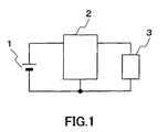
- FIG. 1 is a circuit block diagram showing a schematic configuration of a battery-driven electronic device according to a first embodiment of the present invention.
- reference numeral 1 denotes a battery employing lithium cobaltate as the positive electrode, graphite as the negative electrode, and a nonaqueous solvent containing lithium supporting electrolyte as the electrolyte and having discharge characteristics that are sloped over time with a battery voltage change ratio of 0.25 or more, as opposed to the conventional lithium ion battery having an average battery voltage of 3.7 V at room temperature as the discharge characteristics.
- the battery voltage change ratio refers to a value obtained by dividing a voltage difference (Ec - Ed) by Ec, where Ec is the open circuit voltage after the rated charge end voltage is reached, and Ed is the open circuit voltage after the rated discharge end voltage is reached.
- Reference numeral 2 denotes a step-up and -down converter using the battery 1 as its input source
- reference numeral 3 denotes a load to which the output voltage of the step-up and -down converter 2 is input.
- FIG. 2 shows the typical discharge characteristics (a) of the battery 1 and the voltage (b) required to be supplied to the load 3 and also shows the discharge characteristics (c) of the conventional lithium ion battery for comparison.
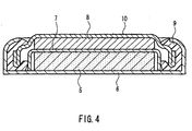
- FIG. 4 is a cross-sectional view showing the structure of a coin-type cell for evaluation that is produced as the battery 1. FIG. 4 will be described.
- 7.5 g of negative electrode powder was mixed to produce a negative electrode mixture.
- 7.5 g of positive electrode powder, 2 g of a conducting agent, and 0.5 g of polyvinylidene fluoride as a binding agent were mixed to produce a positive electrode mixture.
- 0.1 g of the mixture was molded by pressing into an electrode 5 with a diameter of 17.5 mm and the electrode was placed in a case 6.
- a microporous polypropylene separator 7 was placed on the electrode 5.
- a counter electrode 8 for a test was spaced apart from the electrode 5 by the microporous polypropylene separator 7.
- metallic lithium is used for the counter electrode 8 for a test.
- a mixed solution of ethylene carbonate (EC) and diethyl carbonate (DEC) at a volume ratio of 1:1 in which 1.5 mol/liter of a supporting salt LiPF 6 were dissolved was poured into the coin-type cell for evaluation as a nonaqueous electrolyte.
- a sealing plate 10 to which metallic lithium with a diameter of 17.5 mm is attached on its inner face and a polypropylene gasket 9 is attached on its outer circumference was placed for sealing and thus a test cell was produced.
- Positive electrode Negative electrode active material discharge average potential (vs Li) active material composition discharge average potential (vs Li) battery discharge average voltage (V) LiNiO2 3.7 CoSn 0.4 3.3 CoSn2 MnSn Mn2Sn Mn2Sn3 Ti3Sn2 TiSn Ti6Sn5 Ti2Sn Ti1.8Sn Cu3Sn2 CuSn TiSi Ti2Si Fe3Si2 CoSi Co3Si2 Co2Si NiSi Ni2Si Fe2Si Positive electrode Negative electrode active material discharge average potential (vs Li) active material composition discharge average potential (vs Li) battery discharge average voltage (V) LiCoO2 3.8 CoSn 0.4 3.4 CoSn2 MnSn Mn2Sn Mn2Sn3 Ti3Sn2 TiSn Ti6Sn5 Ti2Sn Ti1.8Sn Cu3Sn2 CuSn TiSi Ti2Si Fe3Si2 CoSi Co3Si2 Co2Si Ni2Si Ni2
- Cylindrical batteries were produced as test products, using materials selected from these materials. This production method will be described.
- LiNiO 2 , LiCoO 2 and LiMn 2 O 4 which were positive active materials based on oxides, were examined.
- LiNiO 2 was synthesized by mixing LiOH and Ni(OH) 2 in a predetermined mole ratio and heating the mixture in the air at a temperature of 900°C, and those classified to 100 mesh or smaller were used.
- LiCoO 2 was synthesized by mixing Li 2 CO 3 and Co(OH) 2 in a predetermined mole ratio and heating the mixture in the air at a temperature of 800°C, and those classified to 100 mesh or smaller were used.
- LiMn 2 O 4 was synthesized by mixing Li 2 CO 3 and MnO 2 in a predetermined mole ratio and heating the mixture in the air at a temperature of 800°C, and those classified to 100 meshes or smaller were used.
- a paste for a positive electrode was produced by adding 10 g of acetylene black as a conducting agent, 8 g of polyvinylidene fluoride as a binding agent to 100 g of the positive active material and adding N, N-dimethylformamide as a solvent thereto and mixing them sufficiently.
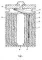
- This paste for a positive electrode was applied onto a core material of aluminum, dried and rolled, and thus a positive electrode 11 shown in FIG. 5 was obtained.
- powdered active materials obtained by pulverizing these active materials, acetylene black as a conducting agent, and styrene butadiene rubber (SBR) as a binding agent were mixed at a weight ratio of 70: 20: 10, and were made into a paste, using N, N-dimethylformamide.
- This paste was applied onto a core material made of copper and then dried, and thus a negative electrode 12 shown in FIG. 5 was obtained.
- a foil was attached to a copper core material to produce a negative electrode.
- a positive lead 14 made of aluminum was attached to aluminum as a positive core material by ultrasonic welding.
- a lead 15 was joined to copper as a negative core material by laser spot welding.
- the entire structure including the positive electrode, the negative electrode and the porous polypropylene separator 13 in the form of a band having a wider width than those of the two electrodes that was interposed therebetween was curled in a coil form.
- polypropylene insulating plates 16 and 17 are disposed on the upper and the lower electrodes, respectively, and the whole structure was inserted into a battery case 18.
- a step portion was formed in the upper portion of the battery case 18, and then a mixed solution of EC and DMC with the same volumes in which 1.5 mole/liter of LiPF 6 was dissolved was poured as a nonaqueous electrolyte. Then, the battery case was sealed with a sealing plate 19 and thus a battery was obtained.
- a comparative battery employing an oxide-based positive electrode and a graphite-based negative electrode was subjected to constant current charging to 4.2 V at an environment temperature of 20°C and a charge current of 0.2 CmA (1C is one hour rate current).
- batteries employing an oxide-based positive electrode and an alloy-based negative electrode or a nitride-based negative electrode were charged to 4.0 V or 3.8 V, respectively.
- batteries employing an organic positive electrode having a thiol or thiolate group containing sulfur and a nitride-based negative electrode or a metallic lithium negative electrode were charged to 3.6 V or 4.0 V, respectively.
- the comparative battery employing an oxide-based positive electrode and a graphite-based negative electrode was discharged to 3.0 V at a current of 0.2 CmA.
- all the batteries used in the examples were discharged to 1.5 V
- discharge was performed to a predetermined voltage at a discharge current with a current density of 2 CmA.
- the battery voltage, the discharge shape, the discharge capacity and the like of the battery systems obtained by combining various positive and negative active materials with this cylindrical battery were measured.
- FIG. 6 shows the discharge characteristics of the combinations of various active materials, using the thus obtained cylindrical batteries.
- a battery A exhibits the characteristics of a battery having a relatively high voltage that employs an oxide-based positive electrode and a graphite-based negative electrode.
- Batteries B, C and D exhibit the characteristics of batteries that employ an oxide-based positive electrode and an alloy-based negative electrode or a nitride-based negative electrode.
- a battery E exhibits the characteristics of a battery that employ an organic positive electrode having a thiolate or thiol group containing sulfur and a nitride-based negative electrode.
- materials having a large discharge capacity tend to have a large battery voltage change ratio, that is, tend to have discharge characteristics that are sloped over time.
- the batteries having discharge characteristics of a battery voltage change ratio of 0.25 or more is used.
- the batteries of these materials tend to have a low average battery voltage.
- the lithium ion battery made of a new material having the discharge characteristics that the battery voltage change ratio is 0.25 or more used for the battery 1, which is a component of the present invention, has a large discharge capacity, that is, can have a high energy density per unit volume or unit weight.
- the lithium ion battery compared with the discharge characteristics (c) of the conventional lithium ion battery, has the characteristics (a) that the discharge characteristics of the battery are sloped over time, that is, the battery voltage is decreased with discharging, and that the average battery voltage is low.
- (d) denotes the rated charge end voltage of the conventional lithium ion battery
- (e) denotes its discharge last state voltage
- (f) is the rated charge end voltage of the lithium ion battery made of a new material
- (g) denotes its discharge last state voltage.
- (d) - (e) is a voltage decrease due to the discharge of the conventional lithium ion battery
- (f) - (g) is a voltage decrease due to the discharge of the lithium ion battery made of a new material.
- This voltage decrease amount of the lithium ion battery made of a new material is larger, and the absolute level thereof is smaller. Therefore, in a battery-driven electronic device having the conventional configuration, the battery voltage becomes below the voltage (b) required to be supplied to the load 3 at an earlier time (T2) than the use time (T1) of the discharge characteristics (c) of the conventional lithium ion battery.
- an operation can be performed as follows. As shown in FIG. 3, when the discharge characteristics (a) of the battery 1 are higher than the voltage (b) required to be supplied to the load 3, the step-up and -down converter 2 operates so as to lower the voltage (indicated by an arrow D), and when the discharge characteristics (a) of the battery 1 become below the voltage (b) required to be supplied to the load 3, the step-up and -down converter 2 operates so as to raise the voltage (indicated by an arrow U).
- the use time (T3) that is significantly longer than the use time (T2) for the case in which the step-up and -down converter 2 is not incorporated and that exceeds the use time (T1) of the conventional lithium ion battery can be realized, and thus the large discharge capacity of the battery 1, that is, the energy accumulated in the battery can be utilized effectively, so that a long term use can be attained.
- the battery use time is 10 hours, which is two hours longer.
- FIG. 8 is a diagram showing the configuration of a battery-driven electronic device and mobile communications equipment according to a second embodiment of the present invention.
- This embodiment is configured such that the load includes a power amplifier for wireless transmission that sends a burst-like signal as in the time-division multiplex system.
- reference numeral 21 denotes a battery having the profile that the power density is higher than that of a battery having a commonly used composition, but the discharge characteristics are sloped over time.
- Reference numeral 22 denotes a step-up and -down converter using the battery 21 as the input.
- Reference numeral 23 denotes a power amplifier to which the output voltage of the step-up and - down converter is input.
- Reference numeral 25 denotes an input terminal of the power amplifier 23, and reference numeral 26 denotes an output terminal of the power amplifier 23.
- Reference numeral 24 denotes controlling means for performing control such that the output voltage of the step-up and -down converter 22 is supplied to the power amplifier 23 during a period in which the power amplifier 23 operates to amplify a transmission signal.
- the power amplifier 23 sends out a burst-like signal, so that the controlling means 24 supplies power only at the time of sending out signals of the power amplifier 23 for power saving purposes.
- the power amplifier 23 amplifies the power of the signals input from the input terminal 25 and outputs the amplified signals.
- a supply voltage of at least a certain level is necessary in the power amplifier 23 for this power amplification.
- the power loss in the power amplifier 23 is increased.
- the configuration has been as follows.
- the supply voltage necessary for a power amplifier of the PDC (Personal Digital Cellular) system is 3 V, and the output voltage of the conventional lithium ion battery having an average battery voltage of 3.7 V and a discharge capacity of 800 mAh and employing lithium cobaltate as the positive electrode, carbon as the negative electrode and a nonaqueous solvent containing a lithium supporting electrolyte as the electrolyte is input directly to the power amplifier.
- the output voltage of the conventional lithium ion battery having an average battery voltage of 3.7 V and a discharge capacity of 800 mAh and employing lithium cobaltate as the positive electrode, carbon as the negative electrode and a nonaqueous solvent containing a lithium supporting electrolyte as the electrolyte is input directly to the power amplifier.
- the power consumption of a portable telephone having an increasing number of functions tends to increase, it is necessary to increase the capacity of the battery in order to increase the use time of the portable telephone, as described above.
- the lithium ion battery made of a new material 21 employing LiNiO 2 as the positive active material, Ti 6 Sn 5 as the negative active material and having an average battery voltage of 3.3 V and a discharge capacity of 1100mAh is combined with a step-up and -down converter 22, when the voltage of the battery 21 is higher than the supply voltage of the power amplifier 23, the step-up and -down converter 22 supplies a necessary voltage to the power amplifier 23 by an operation of lowering the voltage, so that the efficiency of the power amplifier 23 becomes better.
- the step-up and -down converter 22 converts to a necessary voltage for the power amplifier 23 by an operation of raising the voltage, so that the energy of the battery 21 can be utilized effectively, and a long term use can be attained.
- FIG. 9 is a configuration diagram of a battery-driven electronic device and mobile communications equipment according to a third embodiment of the present invention.
- This embodiment is configured such that the load includes a power amplifier for wireless transmission of the CDMA (Code Division Multiple Access) system.
- reference numeral 21 denotes a battery having a profile that the power density is higher than that of a battery having a commonly used composition, but the discharge characteristics are sloped over time.
- Reference numeral 22 denotes a step-up and -down converter to which the output voltage of the battery 21 is input
- reference numeral 23 denotes a power amplifier using the output voltage of the step-up and -down converter as the supply voltage.
- Reference numeral 25 denotes an input terminal of the power amplifier 23, and reference numeral 26 denotes an output terminal of the power amplifier 23.
- Reference numeral 24 denotes controlling means for controlling the output voltage of the step-up and - down converter 23.
- the power amplifier 23 needs a supply voltage of at least a certain level, depending on the transmission power. On the other hand, if the supply voltage is too high, the power loss in the power amplifier 23 increases. That is to say, for power amplifier 23, there is a preferable supply voltage depending on the transmission power.
- the controlling means 24 has a function for controlling the supply voltage to the power amplifier 23 whose transmission power is varied in accordance with the use environment of the battery-driven electronic device of this embodiment such as the state of radio waves or the distance to the radio base station.
- FIG. 10 shows the discharge characteristics of the battery 21 and (f) is a variable range of the supply voltage required by the load.
- (g) shows the general discharge characteristics of the conventional lithium ion battery for comparison.
- FIG. 11A is a characteristics diagram showing the relationship between the output power of the amplifier, which is the transmission power of the power amplifier 23, and the supply voltage required by the power amplifier 23.
- FIG. 11B is a diagram showing the output power of the amplifier, which is the transmission power of the power amplifier 23, and the event probability of the output power. As shown in FIG. 11B, the event probability is high substantially in the center, and as a result, for the supply voltage required by the power amplifier 23, the central voltage in the variation range is required most.
- the variable range of the supply voltage of the power amplifier 23 of the CDMA system is about 1.5 V to 3.5 V.
- the conventional configuration was such that the output voltage of the conventional lithium ion battery having an average battery voltage of 3.7 V and a discharge capacity of 800 mAh and employing lithium cobaltate as the positive electrode, carbon as the negative electrode and a nonaqueous solvent containing a lithium supporting electrolyte as the electrolyte as shown in the discharge characteristics (g) in FIG. 10 was input to the power amplifier via a step-down converter.
- this embodiment is configured such that the lithium ion battery made of a new material 21 employing LiNiO 2 as the positive active material, Ti 6 Sn 5 as the negative active material and having an average battery voltage of 3.3 V and a discharge capacity of 1100mAh as shown in the discharge characteristics (d) in FIG. 10 is combined with the step-up and -down converter 22.
- the voltage change width of the battery 21 is large, and even if the variable range of the supply voltage of the power amplifier 23 is large, the step-up and - down converter 22 can be used both for the operation of lowering the voltage and the operation of raising the voltage, so that the energy of the battery 21 that has a larger capacity can be utilized effectively, and the battery 21 can be used for a longer time.
- the efficiency since the output voltage of the battery 21 becomes close to the output voltage of the step-up and -down converter 22 applied to the power amplifier 23, the efficiency also is better.
- FIG. 12 is a characteristics diagram of the conversion efficiency of the step-up and -down converter that is produced as a test product.
- FIG. 12 shows a change of the conversion efficiency when the output voltage is fixed to 3.5 V, the output current is fixed to 142 mA, and the input voltage is changed from 2.5 V to 5 V. As seen from the efficiency characteristics, when the input voltage is close to the output voltage, the efficiency of the step-up and -down converter is good.
- FIG. 13 is a characteristics diagram of the conversion efficiency of the same step-up and -down converter when the input voltage is fixed to 3.5 V, the output power is fixed to 0.5 W, and the output voltage is changed from 2.5 V to 4.5 V.
- the efficiency is better.
- the battery 21 and the power amplifier 23 can be coupled directly, and therefore high efficiency can be attained. Thus, the battery use time can be prolonged.
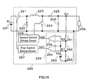
- FIG. 14 is a circuit diagram showing the configuration of a battery-driven electronic device according to a fourth embodiment of the present invention.
- a step-up and -down converter 200 used in the battery-driven electronic device of this embodiment includes a step-down converting portion including first switching means 221, first rectification switching means 222 and an inductor 223, and a step-up converting portion sharing the inductor 223 with the step-sown converter portion and including second switching means 224 and second rectification switching means 225.
- the step-up and -down converter 200 has a detecting circuit 226, a first control driving circuit 227, and a second control driving circuit 228.
- the detecting circuit 226 detects a voltage at an output capacitor 205 that is divided by a first detection resistor 261 having a resistance R1, a second detection resistor 262 having a resistance R2 and a third detection resistor 263 having a resistance R3, and compares the divided voltages with a reference voltage Eb that is output from a reference voltage source 260.
- the first control driving circuit 227 turns the first switching means 221 to be on/off so that the voltage Eo of the output capacitor 205 is adjusted to Eoh. Therefore, the voltage Eo becomes higher than the second preset value Eol, and in the detecting circuit 226, the second control signal Ve2 is decreased to the "L" level.
- the second control driving circuit 228 fixes the second switching means 224 to operate at a duty ratio of 0%, that is, to be in the off-state.
- the first switching means 221 and the first rectification means 222 that is operated to be on/off in conjunction with it accumulate and release magnetic energy with respect to the inductor 223, so that the step-up and -down converter 200 operates as a step-down converter that supplies the voltage Eoh from the output capacitor 205 to the loads 206 via the second rectification switching means 225.
- the first control driving circuit 227 fixes the first switching means 221 to operate at a duty ratio of 100%, that is, to be in the on-state.
- the second control signal Ve2 is increased from the "L" level.
- the second control driving circuit 228 turns the second switching means 224 to be on/off so that the voltage Eo of the output capacitor 205 is adjusted to the second preset value Eol.
- the 100% duty ratio operation is still performed in the step-down converting portion.
- the second switching means 224 and the second rectification means 225 that is operated to be on/off in conjunction with it accumulate and release magnetic energy with respect to the inductor 223, so that the step-up and - down converter 200 operates as a step-up converter that supplies the voltage Eol from the output capacitor 205 to the loads 206.
- the step-up and -down converter 200 that is interposed between the battery 201 and the load 206 can be short-circuited.
- no switching means performs a switching operation, so that the characteristics of such a high efficiency in which switching loss does not occur are exhibited.
- the step-up and - down converter 200 can be operated with a high efficiency, the battery use time can be prolonged.
- diodes are used as the first rectification switching means 222 and the second rectification switching means 225, but the rectification switching means may be synchronization rectification switching means using switching means typified by MOSFETs or the like in order to decrease the on-voltage during conduction and reduce the conduction loss.
- FIG. 15 is a circuit diagram showing the configuration of a battery-driven electronic device according to a fifth embodiment of the present invention. This embodiment is obtained by adding some elements to the fourth embodiment in order to improve further the effect of the fourth embodiment shown in FIG. 14.
- FIG. 15 is different from FIG. 14 in that third switching means 229 straddling the first switching means 221 and the inductor 223, and a third control driving circuit 290 turning the third switching means 229 to be on when the first control signal Ve1 is in the level that fixes the first switching means 221 to be on and the second control signal Ve2 is in the level that fixes the second switching means 224 to be off are added.
- the third switching means 229 is in the off-state and does not participate in the operation.
- the battery voltage Ei When, the battery voltage Ei satisfies Eol ⁇ Ei ⁇ Eoh, the battery voltage Ei is coupled directly to the output capacitor 205 via the first switching means 221, the inductor 223, and the second rectification switching means 225, which is the same as in the four embodiment.
- the first control signal Ve1 is in the level that fixes the first switching means 221 to be on and the second control signal Ve2 is in the level that fixes the second switching means 224 to be off, the third switching means 229 is in the on-state.
- the third switching means 229 may straddle the second rectification switching means 225, instead of the first switching means 221 and the inductor 223. Which connection should be established can be determined so as to cover a larger conduction loss by comparing the conduction loss of the first switching means 221 and the conduction loss of the second rectification switching means 225.
- the third switching means 229 should be switching means that can control its on- and off-state, regardless of whether the voltage difference between the input terminal and the output terminal is positive or negative in the off-state, for example, a relay or switching means in which two FETs are connected in series such that their body diodes are oriented in opposite directions. Judging from its application, it is preferable that the on-voltage is lower.
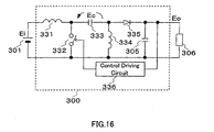
- FIG. 16 is a circuit diagram showing the configuration of a battery-driven electronic device according to a sixth embodiment of the present invention.
- a step-up and -down converter 300 used in the battery-driven electronic device of this embodiment includes a first inductor 331, switching means 332, a coupling capacitor 333, a rectification switching means 335, a second inductor 334, an output capacitor 305 and a control driving circuit 336.
- the first inductor 331 and the switching means 332 form a series circuit and are connected to a battery 301.
- the coupling capacitor 333 and the second inductor 334 form a series circuit and are connected to the opposite ends of the switching means 332.
- the rectification switching means 335 and the output capacitor 305 form a series circuit and are connected to the opposite ends of the rectification switching means 335.
- a converter having this configuration is a step-up and -down converter referred to as Sepic (Single Ended Primary Inductive Converter).
- the control driving circuit 336 has a function to control the switching means 332 to be on/off so that the voltage in the output capacitor 305 is adjusted to a predetermined value required to be supplied to the load 306.
- the capacitance of the coupling capacitor 333 is sufficiently large, and the coupling capacitor 333 is regarded as the voltage source of its voltage Ec.
- the battery voltage Ei is applied to the first inductor 331, and current from the battery 301 flows through the first inductor 331, and magnetic energy is accumulated.
- the voltage Ec of the coupling capacitor 333 is applied to the second inductor 334, and current from the coupling capacitor 333 flows through the second inductor 334, and magnetic energy is accumulated.
- the rectification switching means 335 is off, because a voltage is applied in the opposite direction, and electrostatic energy accumulated in the output capacitor 305 is discharged and supplied to the load 306. This period is taken as Ton.
- the switching means 332 when the switching means 332 is turned off, the voltage of the first inductor 331 is inverted. At the same time, the voltage of the second inductor 334 to which the coupling capacitor 333 is connected also is inverted. As a result, the rectification switching means 335 becomes on, and current flows from the battery 301 to charge the output capacitor 305 via the first inductor 331, the coupling capacitor 333, and the rectification switching means 335. This current releases the magnetic energy accumulated in the first inductor 331.
- the voltage Eo of the output capacitor 305 is applied to the second inductor 334, and current from the second inductor 334 flows to the output capacitor 305 via the rectification switching means 335, and the accumulated magnetic energy is released at the same time. This period is taken as Toff.
- the magnetic energy is accumulated and released repeatedly in the first inductor 331 and the second inductor 334, and the coupling capacitor 333 and the output capacitor 305 are charged and discharged repeatedly.
- the condition that allows the accumulation and the release of the energy to be in equilibrium is that the current flowing through the first inductor 331 and the current flowing through he second inductor 334 are in equilibrium.
- This feature of the step-up and -down converter Sepic is that since the first inductor 331 is provided in the input portion of the converter, the input current hardly can be varied and can be continuous.
- This aspect will not be described in detail, but it is known that the first inductor 331 and the second inductor 334 are magnetically coupled and its coupling coefficient is adjusted so that the input current can be zero-ripple current.
- the battery 301 has the characteristics that it tends to be weak with respect to a current in the form of pulse that varies sharply, thereby leading to short life time and reducing the capacity.
- the Sepic which hardly has sharp variations in the input current, is used as the step-up and -down converter, so that the disadvantages in the characteristics of the battery 301 as described above can be compensated and the lifetime is prevented from being short and a long time use can be achieved.
- a diode is used as the rectification switching means 335, but the rectification switching means may be synchronization rectification switching means using switching means typified by MOSFETs or the like in order to decrease the on-voltage during conduction and reduce the conduction loss.
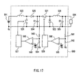
- FIG. 17 is a circuit diagram showing the configuration of a battery-driven electronic device according to a seventh embodiment of the present invention.
- a step-up and -down converter 500 used in the battery-driven electronic device of this embodiment includes a step-up converter including first switching means 524, first rectification switching means 525, an inductor 523, and a first capacitor 504, and a step-down converter that receives an intermediate voltage E1, which is the output voltage of the step-up converter, and includes second switching means 521, second rectification switching means 522, a second inductor 526, and a second capacitor 505.
- step-up converter an intermediate voltage in the first capacitor 504 is detected, and control is performed so as to be stabilized to the predetermined intermediate voltage E1.
- step-down converter a voltage in the second capacitor 505, which will be the output voltage Eo of the step-up and -down converter 500, is detected, and control is performed so as to be stabilized to a voltage necessary for the load.
- the intermediate voltage E1 becomes close to the output voltage of the battery 501 independently from the step-up converter.
- the step-up converter controls such that the intermediate voltage E1 is stabilized.
- the output voltage Eo to be supplied to the load is stabilized by the step-down converter.
- the circuit configuration of this embodiment is different from that of the fourth embodiment in that in the fourth embodiment, the step-down converter is in the front stage and the step-up converter is in the rear stage, whereas in this embodiment, the step-up converter is in the front stage and the step-down converter is in the rear stage.
- the current flowing to the output capacitor 205 of the step-up and -down converter 200 shown in FIG. 14 is not continuous, so that it is necessary to increase the capacitance of the output capacitor 205 in order to reduce the ripples of the output voltage.
- the ripple voltage of the supply voltage should be reduced as much as possible because it may cause the strain of the power amplifier for wireless transmission.
- the power for wireless transmission also is changed to substantially the maximum extent, and therefore it is necessary to change the supply voltage, that is, the output voltage of the step-up and -down converter from a small value to a large value. Therefore, the supply voltage should be shifted rapidly in order to increase the transmission time as much as possible.
- the output current from the step-down converter in the rear stage is continuous, so that it is possible to reduce both the ripple voltage and the capacitance of the output capacitor.
- the lower limit is a voltage that can provide the power at the maximum voltage and the maximum current required by the load 506, that is, a voltage obtained by adding the maximum voltage to a value obtained by multiplying a resistance component between the first capacitor 504 and the second capacitor 505 by the maximum current.
- diodes are used as the first rectification switching means 525 and the second rectification switching means 522, but the rectification switching means may be synchronization rectification switching means using switching means typified by MOSFETs or the like in order to decrease the on-voltage during conduction and reduce the conduction loss.
- FIG. 18 is a block diagram showing the circuit configuration of a portable telephone in which the battery-driven electronic devices of the first to the seventh embodiment is mounted as mobile communications equipment according to an eight embodiment of the present invention.
- data generated in a baseband portion 1803 are modulated in a modulating portion 1804, and signals output from the modulating portion 1804 are amplified to a required power in an amplifying portion 1805 and radiated from an antenna 1809 via a sending/receiving separating circuit 1808.
- the signals received by the antenna 1809 are amplified to a required power in a signal-receiving circuit 1807 via the sending/receiving separating circuit 1808, are frequency-converted, if necessary, and are demodulated to baseband signals in a demodulating portion 1806 and input to the baseband portion 1803.
- the step-up and -down converter 1802 receives the output voltage of the battery 1801 and supplies the voltage to the amplifying portion 1805, and changes the supply voltage in accordance with power that is output from the amplifying portion 1805 so as to increase the efficiency of the amplifying portion 1805.
- a capacitor may be inserted in parallel to the battery between the battery and the step-up and -down converter.
- the ripple current of the step-up and -down converter can be prevented from flowing through the battery, so that the use time of the battery can be prolonged. Furthermore, it is possible to reduce the ripple voltage generated between the battery and the step-up and -down converter.
- the discharge capacity is larger (the energy density per unit volume or unit weight is higher).
- the step-up and -down converter performs an operation of lowering the voltage when the discharge characteristics of the battery are higher than the supply voltage required by the load, and the step-up and - down converter performs an operation of raising the voltage when the discharge characteristics of the battery are lower than the supply voltage required by the load, so that the large discharge capacity (high energy density) of the battery can be utilized effectively and the battery-driven electronic device and the mobile communications equipment can be used for a longer time.
- the supply voltage to the load is within the range in which the battery voltage of the battery is changed with the discharge of the battery, and further the average battery voltage associated with the discharge of the battery is matched to the supply voltage to the load, so that the advantage that the battery use time of the battery-driven electronic device can be prolonged can be obtained.
- the advantageous effects that the step-up and -down converter can be operated with high efficiency, and the battery use time of the battery-driven electronic device can be prolonged can be obtained by operating in the following manner.
- the entire variation range or a part thereof matches the entire battery voltage change range of the battery or a part thereof.
- the voltage required to be supplied to the load has a predetermined variation range
- the probability distribution of the required supply voltage in the variation range has one peak value, and the difference between the required supply voltage at the peak of this probability distribution and the average battery voltage of the battery is within a predetermined potential difference range.
- the step-up and -down converter when the difference between the supply voltage to the load and the output voltage of the battery is within a predetermined potential defference range, the step-up and -down converter has a function to fix the active component interposed between its input and its output to be on, so that the following advantageous effects can be obtained: high efficiency characteristics in which the switching loss does not occur are exhibited; and the battery use time of the battery-driven electronic device can be prolonged.
- the step-up and -down converter can has a function to short-circuit some or all of the components interposed between its input and its output, so that when the difference between the supply voltage to the load and the output voltage of the battery is within a predetermined potential difference range, the following advantageous effects can be obtained: the switching loss does not occur; the conduction loss also can be reduced; the efficiency can be improved further, and the battery use time of the battery-driven electronic device and the mobile communications equipment can be prolonged.
- the ripple components of the input current of the step-up and -down converter can be reduced. That is to say, the following advantageous effects can be obtained: sharp variations in the discharge current of the battery can be reduced, so that characteristics of the battery can be prevented from deteriorating, and the lifetime can be prevented from being short and the use time can be prolonged.
- the step-up and -down converter having a combination of a step-up converter in the front stage and a step-down converter in the rear stage, in addition to the advantageous effect that the battery use time can be prolonged, output ripples can be reduced, and output voltage switching can be performed at a high speed, and thus this is an optimal configuration when a power amplifier for wireless transmission of the CDMA (Code Division Multiple Access) system is used as the load.
- CDMA Code Division Multiple Access
Landscapes
- Engineering & Computer Science (AREA)
- Power Engineering (AREA)
- Charge And Discharge Circuits For Batteries Or The Like (AREA)
- Secondary Cells (AREA)
- Dc-Dc Converters (AREA)
- Mobile Radio Communication Systems (AREA)
- Transmitters (AREA)
- Transceivers (AREA)
Abstract
The present invention provides a battery-driven electronic device
for which a long time use of the battery can be achieved and mobile
communications equipment such as a portable telephone. Even if the
time at which the output voltage of a battery 201 becomes below the
supply voltage required by a load 206 including a power amplifier for
wireless communications comes earlier than a conventional lithium ion
battery because of its discharge characteristics that the battery voltage
change ratio is 0.25 or more, a step-up and -down converter 200 operates
as follows. When the output voltage of the battery is higher than the
supply voltage required by the load, the voltage is set to a predetermined
supply voltage by the step-down operation mode. When the output
voltage of the battery is decreased and becomes lower than the supply
voltage required by the load, the voltage is set to a predetermined supply
voltage by the step-up operation mode. Thus, even for a battery
employing a new material having a high energy density, a long term use
of the battery can be achieved.
Description
The present invention relates to a battery-driven electronic device
employing a battery as its input source and mobile communications
equipment such as portable telephones and portable communications
terminals in which such a battery-driven electronics device is mounted.
For wireless communications devices, information terminals and
other electronic devices employing batteries as their power source for
which the convenience of portability is required, there is a demand for a
long time use after charging when the battery is a secondary battery or
after battery exchange when the battery is a primary battery, in addition
to compactness and lightweightness.
The configuration shown in FIG. 19 commonly is used for such a
battery-driven electronic device. As shown in FIG. 19, a conventional
battery-driven electronic device uses as its input source a battery typified
by a conventional lithium ion battery, more specifically, a battery 401
employing lithium cobaltate as the positive electrode, graphite as the
negative electrode, and a nonaqueous solvent containing lithium
supporting electrolyte as the electrolyte and having an average battery
voltage of 3.7 V at room temperature as the discharge characteristics, and
supplies a predetermined voltage Eo to a load 406 via a step-down
converter constituted by switching means 402, rectification switching
means 403, an inductor 404, and an output capacitor 405.
Hereinafter, the terms will be defined. An "average battery
voltage" is defined as a voltage obtained by dividing the time integration
of the battery voltage when discharge is performed at a rated current
from the rated charge state to the rated discharge capacity by the
discharge time. A "rated charge end voltage" is defined as a battery
voltage at the end of a charge operation necessary to obtain the rated
discharge capacity. A "rated discharge end voltage" is defined as a
battery voltage when the rated discharge capacity is obtained. A "rated
discharge last stage voltage" is defined as a battery voltage when a large
change occurs in the slope of the discharge voltage characteristics during
discharging at the rated current.
First, the operation of the step-down converter will be described.
When the voltage of the battery 401 is taken as Ei and the switching
means 402 is turned on, a difference (Ei-Eo) between the output voltage of
the battery (hereinafter, referred to as a "battery voltage") Ei and a
supply voltage Eo is applied to the inductor 404. In this case, current
flows from the battery 401 to the output capacitor 405 via the switching
means 402 and the inductor 404. The current in the inductor 404
increases, so that magnetic energy is accumulated in the inductor 404.
This period is taken as Ton.
Then, when the switching means 402 is turned off, the voltage of
the inductor 404 is inverted, and the rectification switching means 403 is
turned on, and thus the supply voltage Eo is applied to the inductor 404.
In this case, the current in the inductor 404 flows through the
rectification switching means 403 to the output capacitor 405. This
current is decreased, and the magnetic energy accumulated in the
inductor 404 is released. This period is taken as Toff.
When the accumulation and the release of the magnetic energy is
in equilibrium through such an on/off operation of the switching means
402, the increase and the decrease in the current flowing in the inductor
404 is in equilibrium. When the inductance of the inductor 404 is taken
as L, the following relationship is satisfied:
(Ei-Eo)·Ton/L=Eo·Toff/L
When the switching cycle T = Ton+Toff, the following relationship
is satisfied between the input and the output of the step-down converter:
Eo/Ei=Ton/T
That is to say, in the step-down converter, the supply voltage Eo to
the load 406 can be adjusted under the limitation of Ei > Eo with respect
to variations of the battery voltage Ei by the on/off control of the
switching means 402.
On the other hand, when the voltage Eo that should be supplied to
the load 406 is higher than the battery voltage Ei, a step-up converter is
used instead of the step-down converter. The configuration using a
step-up converter is disclosed, for example, in JP 4-315320 A.
The conventional lithium ion battery as the battery 401 is
characterized in that the discharge characteristics are flat, that is, a
reduction in a battery voltage associated with discharge is small (the
battery voltage change ratio is small). Thus, the battery voltage can be
close to the voltage that is required to be supplied to the load 406, and the
loss in the step-down converter can be decreased. In addition, this
relationship does not change with discharging, so that the energy of the
battery can be used efficiently.
In the configuration of the conventional battery-driven electronic
device, when a step-down converter is used, the battery voltage Ei should
be higher than the voltage Eo that is required to be supplied to the load.
On the other hand, it is better that the battery voltage Ei is close to the
supply voltage Eo in order to operate the step-down converter efficiently.
When a step-up converter is used, the battery voltage Ei should be lower
than the voltage Eo that is required to be supplied to the load. In this
case as well as in the case of the step-down converter, it is better that the
battery voltage Ei is close to the supply voltage Eo in order to operate the
step-up converter efficiently.
Therefore, the characteristics required for batteries are that the
battery voltage Ei is slightly higher or slightly lower than the supply
voltage Eo and that the discharge characteristics are flat. For batteries,
research has been carried out for achieving large capacity while satisfying
these characteristics. The battery use time, which is a period until the
battery voltage that decreases with discharging reaches the lower limit of
the voltage at which the battery can be used, has been prolonged by
achieving a large capacity with the weight and volume unchanged.
The flatter the discharge characteristics are, the more significant
a decrease of the battery voltage tends to be when approaching the last
stage of discharging. That is to say, the energy that is left at this point is
small. The conventional lithium ion battery employing lithium cobaltate
as the positive electrode, graphite as the negative electrode, and a
nonaqueous solvent containing lithium supporting electrolyte as the
electrolyte and having an average battery voltage of 3.7 V at room
temperature has the most excellent discharge characteristics at present.
However, although battery-driven electronic devices have become
more compact and high performance and there is a demand for
improvement in compactness and large capacity of batteries, that is,
improvement in energy density, the theoretical limit is almost reached in
terms of large capacity for the above-described conventional lithium ion
batteries. Then, a lithium ion battery employing a new material that
allows improvement of the energy density of batteries is necessary.
However, the batteries made of a material that can realize a high energy
density have problems in that the average battery voltage is lower and
the battery voltage change ratio is larger than those of the conventional
lithium ion batteries.
When the lithium ion battery employing such a new material is
incorporated into equipment in which the conventional lithium ion
battery is used, and the supply voltage required by the load in the
electronic device is between the rated charge end voltage and the rated
discharge end voltage of the battery, then the following problem arises.
The battery voltage is decreased with discharging, and thus the time at
which the battery voltage becomes lower than the supply voltage required
by the load is reached earlier than the conventional lithium ion battery, so
that the advantage of the high energy density resulted from the new
material cannot be utilized. Consequently, the use time of the
equipment is shorter than that of the conventional lithium ion battery.
Furthermore, it is considered that two cells, each of which is a
lithium ion battery made of a new material having a low average battery
voltage and a large battery voltage change ratio, are used to increase the
battery voltage and are combined with a step-down converter. However,
the voltage difference between the input and the output becomes large, so
that it is difficult to realize high efficiency of the step-down converter, and
the input voltage is increased. Therefore, it is necessary to increase the
withstand voltage of capacitors or semiconductors, and therefore the
efficiency is further decreased and the components become larger so that
compactness cannot be achieved.
The present invention is carried out, based on the fact that the
energy of a battery can be utilized effectively by combining a lithium ion
battery made of a new material and a step-up and -down converter, in
order to solve the problem that since a lithium ion battery made of a new
material that can improve the energy density of a battery has a low
average battery voltage and a large battery voltage change ratio, high
capacity energy cannot fully be utilized when this battery is used in a
battery-driven electronic device.
It is an object of the present invention to provide a battery-driven
electronic device that allows a long term use of a battery and can be used
with batteries having various discharge characteristics, and mobile
communications equipment in which such a battery-driven electronic
device is mounted.
In order to achieve the above object, a first battery-driven
electronic device of the present invention includes a battery having
discharge characteristics that a battery voltage change ratio, which is a
value obtained by dividing a voltage difference (Ec-Ed) by Ec, where Ec is
an open circuit voltage after a rated charge end voltage is reached, and Ed
is an open circuit voltage after a rated discharge end voltage is reached, is
0.25 or more; a step-up and -down converter that has an output voltage of
the battery as an input source, performs at least a step-down operation
mode and a step-up operation mode in accordance with the output voltage
of the battery, and outputs a predetermined voltage; and a load to which
the output voltage of the step-up and -down converter is supplied.
According to this configuration, even if the time at which the
output voltage of a battery becomes below the supply voltage required by
a load comes earlier than a conventional lithium ion battery because of
the discharge characteristics that the battery voltage change ratio is 0.25
or more, a step-up and -down converter operates as follows. When the
output voltage of the battery is higher than the supply voltage required
by the load, the voltage is set to a predetermined supply voltage by the
step-down operation mode. When the output voltage of the battery is
decreased and becomes lower than the supply voltage required by the load,
the voltage is set to the predetermined supply voltage by the step-up
operation mode. Thus, even for a lithium secondary battery, for example,
employing a new material having a high energy density, a long term use
of the battery can be achieved.
In order to achieve the above object, a second battery-driven
electronic device of the present invention includes a battery having
discharge characteristics that a battery voltage change ratio, which is a
value obtained by dividing a voltage difference (Ec-Ed) by Ec, where Ec is
an open circuit voltage after a rated charge end voltage is reached, and Ed
is an open circuit voltage after a rated discharge end voltage is reached, is
0.25 or more; a step-up and -down converter that has an output voltage of
the battery as an input source, performs a step-up and -down operation
mode in accordance with the output voltage of the battery, and outputs a
predetermined voltage; and a load to which the output voltage of the
step-up and -down converter is supplied.
According to this configuration, even if the time at which the
output voltage of a battery becomes below the supply voltage required by
a load comes earlier than a conventional lithium ion battery because of
the discharge characteristics that the battery voltage change ratio is 0.25
or more, a step-up and -down converter sets the output voltage of the
battery to the supply voltage required by the load by the step-up and -
down operation mode. Thus, even for a lithium secondary battery, for
example, employing a new material having a high energy density, a long
term use of the battery can be achieved.
In the first and the second battery-driven electronic devices, it is
preferable that the battery is a prismatic battery, and the energy density
per unit volume of the prismatic battery is 460 Wh/1 or more.
Alternatively, in the first and the second battery-driven electronic
devices, it is preferable that the battery is cylindrical battery, and the
energy density per unit volume of the cylindrical battery is 530 Wh/1 or
more.
In the first and the second battery-driven electronic devices, it is
preferable that a voltage required to be supplied to the load is within a
range of the rated charge end voltage and a rated discharge last stage
voltage of the battery. In this case, it is preferable that the difference
between an average battery voltage associated with discharge
characteristics of the battery and the supply voltage to the load is within
a predetermined range.
Thus, the loss in the step-up and -down converter can be reduced,
and the use time of the battery can be prolonged further.
In the first and the second battery-driven electronic devices, it is
preferable that the voltage required to be supplied to the load has a
predetermined variation range, and the entire variation range of the
supply voltage or a part thereof matches the entire range of the rated
charge end voltage and the rated discharge last stage voltage of the
battery or a part thereof. In this case, it is preferable that the voltage
required to be supplied to the load has a predetermined variation range, a
probability distribution of the required supply voltage in the
predetermined variation range has one peak value, and a difference
between the required supply voltage at the peak of the probability
distribution and an average battery voltage associated with discharge
characteristics of the battery is within a predetermined range.
Thus, the loss in the step-up and -down converter can be reduced,
and the use time of the battery can be prolonged further.
In the first and the second battery-driven electronic devices, it is
preferable that the load comprises a power amplifier for wireless
transmission, and such a battery-driven electronic device is mounted in
mobile communications equipment.
In the first battery-driven electronic device, it is preferable that
when a difference between the supply voltage to the load and the output
voltage of the battery is within a predetermined range, the step-up and -
down converter has a function to fix an active component interposed
between its input and its output to be on, because the loss in the step-up
and -down converter can be reduced further, and the use time of the
battery can be prolonged further.
In this case, a step-up and -down converter having a first
configuration includes first switching means whose one end is connected
to one end of the battery; first rectification switching means whose one
end is connected to the other end of the first switching means, and whose
other end is connected to the other end of the battery; an inductor whose
one end is connected to the other end of the first switching means; second
switching means whose one end is connected to the other end of the
inductor, and whose other end is connected to the other end of the battery;
second rectification switching means whose one end is connected to one
end of the second switching means, and whose other end is connected to
one end of the load; an output capacitor whose one end is connected to one
end of the load, and whose other end is connected to the other end of the
battery and the other end of the load and that supplies a voltage to the
load; a detecting circuit that detects the supply voltage at the output
capacitor, outputs an error signal between the detected supply voltage
and a first preset value (Eoh) for performing the step-down operation
mode as a first control signal (Ve1), and outputs an error signal between
the detected supply voltage and a second preset value (Eo1) for performing
the step-up operation mode as a second control signal (Ve2); a first control
driving circuit that controls the first switching means to be on/off so that
the supply voltage is adjusted to the first preset value in accordance with
the first control signal; and a second control driving circuit that controls
the second switching means to be on/off so that the supply voltage is
adjusted to the second preset value in accordance with the second control
signal.
The detecting circuit includes a series circuit of a first detection
resistor, a second detection resistor and a third detection resistor, to
which the supply voltage is applied; a reference voltage source that
outputs a reference voltage; a first error amplifier to which a potential at
a connection point between the first detection resistor and the second
detection resistor and the reference voltage are input, and outputs the
first control signal; and a second error amplifier to which a potential at a
connection point between the second detection resistor and the third
detection resistor and the reference voltage are input, and outputs the
second control signal.
According to this configuration, the step-up and -down converter
having the first configuration first operates as a step-down converter to
adjust the supply voltage to the first preset value when the output voltage
Ei of the battery is higher than the first preset value Eoh. Then, when
the output voltage Ei of the battery is decreased and becomes below the
first preset value Eoh (higher than the second preset value Eol), the
step-up and -down converter stops either the step-down operation or the
step-up operation and operates in the through mode. When the output
voltage Ei of the battery is decreased further and becomes below the
second preset value Eol, the step-up and -down converter operates as a
step-up converter to adjust the supply voltage to the second preset value.
Thus, when the difference between the output voltage Ei of the
battery and the supply voltage Eo to the load is within a predetermined
range (< (Eoh ― Eol)), either the step-down operation or the step-up
operation are stopped, and operation is performed in the through mode.
Therefore, the loss in the step-up and -down converter can be reduced,
and the use time of the battery can be prolonged.
In the first battery-driven electronic device, it is preferable that
when a difference between the supply voltage to the load and the output
voltage of the battery is within a predetermined range, the step-up and -
down converter has a function to short-circuit some or all components
interposed between its input and its output, because the loss in the step-up
and -down converter can be reduced further, and the use time of the
battery can be prolonged further.
In this case, a step-up and -down converter having a second
configuration includes first switching means whose one end is connected
to one end of the battery; first rectification switching means whose one
end is connected to the other end of the first switching means, and whose
other end is connected to the other end of the battery; an inductor whose
one end is connected to the other end of the first switching means; second
switching means whose one end is connected to the other end of the
inductor, and whose other end is connected to the other end of the battery;
third switching means whose one end is connected to one end of the first
switching means, and whose other end is connected to the other end of the
inductor; second rectification switching means whose one end is
connected to one end of the second switching means, and whose other end
is connected to one end of the load; an output capacitor whose one end is
connected to one end of the load, and whose other end is connected to the
other end of the battery and the other end of the load and that supplies a
voltage to the load; a detecting circuit that detects the supply voltage at
the output capacitor, outputs an error signal between the detected supply
voltage and a first preset value for performing the step-down operation
mode as a first control signal, and outputs an error signal between the
detected supply voltage and a second preset value for performing the
step-up operation mode as a second control signal; a first control driving
circuit that controls the first switching means to be on/off so that the
supply voltage is adjusted to the first preset value in accordance with the
first control signal; a second control driving circuit that controls the
second switching means to be on/off so that the supply voltage is adjusted
to the second preset value in accordance with the second control signal,
and a third control driving circuit that turns the third switching means
on, when the first control signal is in a level that fixes the first switching
means to be on, and the second control signal is in a level that fixes the
second switching means to be off.
According to this configuration, in addition to the advantages
provided by the step-up and -down converter having the first
configuration, the loss can be reduced more than in the step-up and -down
converter having the first configuration, and the use time of the battery
can be prolonged further, because the inductor having a large DC
resistance component, which constitutes a loss, can be short-circuited by
turning the third switching means on.
In the first battery-driven electronic device, it is preferable that a
step-up and -down converter having a third configuration includes first
switching means whose one end is connected to one end of the battery;
first rectification switching means whose one end is connected to the
other end of the first switching means, and whose other end is connected
to the other end of the battery; an inductor whose one end is connected to
the other end of the first switching means; second switching means whose
one end is connected to the other end of the inductor, and whose other end
is connected to the other end of the battery; second rectification switching
means whose one end is connected to one end of the second switching
means, and whose other end is connected to one end of the load; third
switching means whose one end is connected to one end of the inductor,
and whose other end is connected to the other end of the second
rectification switching means; an output capacitor whose one end is
connected to one end of the load, and whose other end is connected to the
other end of the battery and the other end of the load and that supplies a
voltage to the load; a detecting circuit that detects the supply voltage at
the output capacitor, outputs an error signal between the detected supply
voltage and a first preset value for performing the step-down operation
mode as a first control signal, and outputs an error signal between the
detected supply voltage and a second preset value for performing the
step-up operation mode as a second control signal; a first control driving
circuit that controls the first switching means to be on/off so that the
supply voltage is adjusted to the first preset value in accordance with the
first control signal; a second control driving circuit that controls the
second switching means to be on/off so that the supply voltage is adjusted
to the second preset value in accordance with the second control signal,
and a third control driving circuit that turns the third switching means
on, when the first control signal is in a level that fixes the first switching
means to be on, and the second control signal is in a level that fixes the
second switching means to be off.
According to this configuration, in addition to the advantages
provided by the step-up and -down converter having the first
configuration, the loss can be reduced more than in the step-up and -down
converter having the first configuration, and the use time of the battery
can be prolonged further, because the inductor having a large DC
resistance component, which constitutes a loss, can be short-circuited by
turning the third switching means on.
In the second battery-driven electronic device, it is preferable that
a step-up and -down converter having a fourth configuration includes a
first inductor whose one end is connected to one end of the battery;
switching means whose one end is connected to the other end of the first
inductor and whose other end is connected to the other end of the battery;
a coupling capacitor whose one end is connected to the other end of the
first inductor; a second inductor whose one end is connected to the other
end of the coupling capacitor and whose other end is connected to the
other end of the battery; rectification switching means whose one end is
connected to one end of the second inductor, and whose other end is
connected to one end of the load; an output capacitor whose one end is
connected to one end of the load, and whose other end is connected to the
other end of the battery and the other end of the load and that supplies a
voltage to the load; and control driving means that controls the switching
means to be on/off in order to adjust the supply voltage to a
predetermined value required to be supplied to the load.
According to this configuration, the ripple component of the input
current can be reduced, that is, sharp variations in the discharge current
of the battery can be reduced. Therefore, the characteristics of the
battery can be prevented from deteriorating, the lifetime can be
prevented from being short, and the use time of the battery can be
prolonged.
In the first battery-driven electronic device, it is preferable that a
step-up and -down converter having a fifth configuration includes a first
inductor whose one end is connected to one end of the battery; switching
means whose one end is connected to the other end of the first inductor,
and whose other end is connected to the other end of the battery; first
rectification switching means whose one end is connected to the other end
of the first inductor; a first capacitor whose one end is connected to the
other end of the first rectification switching means, and whose other end
is connected to the other end of the battery; second switching means
whose one end is connected to the other end of the first rectification
switching means; second rectification switching means whose one end is
connected to the other end of the second switching means, and whose
other end is connected to the other end of the battery; a second inductor
whose one end is connected to one end of the second rectification
switching means, and whose other end is connected to one end of the load;
a second capacitor whose one end is connected to one end of the load, and
whose other end is connected to the other end of the battery and the other
end of the load and that supplies a voltage to the load; a first detecting
circuit that detects an intermediate voltage (E1) at the first capacitor, and
outputs an error signal between the detected intermediate voltage and an
intermediate voltage preset value for performing the step-up operation
mode as a first control signal; and a second detecting circuit that detects
the supply voltage (Eo) at the second capacitor, and outputs an error
signal between the detected supply voltage and a supply voltage preset
value for performing the step-down operation mode as a second control
signal; a first control driving circuit that controls the first switching
means to be on/off so that the intermediate voltage at the first capacitor is
adjusted to the intermediate voltage preset value in accordance with the
first control signal; a second control driving circuit that controls the
second switching means to be on/off so that the supply voltage at the
second capacitor is adjusted to the supply voltage preset value in
accordance with the second control signal.
According to this configuration, unlike the step-up and -down
converters having the first to the fourth configuration, with the
configuration in which the step-up converter is in the front stage and the
step-down converter is in the rear stage, output current is continuous in
the step-down converter in the rear stage. Therefore, both a reduction of
ripple voltage and a reduction of the capacitance of the second capacitor
can be achieved. Thus, the present invention can be adapted to an
application requiring the supply voltage to be changed significantly in a
short time.
In this case, it is preferable that the intermediate voltage preset
value is set to a value obtained by adding a maximum voltage required by
the load to a value obtained by multiplying a resistance component
between the first capacitor and the second capacitor by a maximum
current required by the load.
Thus, the step-down converter in the rear stage can operate with
such a good efficiency that the second switching means is constantly on,
when the load requires the maximum voltage and the maximum current.
Hereinafter, embodiments of the present invention will be
described with reference to the drawings.
FIG. 1 is a circuit block diagram showing a schematic
configuration of a battery-driven electronic device according to a first
embodiment of the present invention. In FIG. 1, reference numeral 1
denotes a battery employing lithium cobaltate as the positive electrode,
graphite as the negative electrode, and a nonaqueous solvent containing
lithium supporting electrolyte as the electrolyte and having discharge
characteristics that are sloped over time with a battery voltage change
ratio of 0.25 or more, as opposed to the conventional lithium ion battery
having an average battery voltage of 3.7 V at room temperature as the
discharge characteristics. Herein, the "battery voltage change ratio"
refers to a value obtained by dividing a voltage difference (Ec - Ed) by Ec,
where Ec is the open circuit voltage after the rated charge end voltage is
reached, and Ed is the open circuit voltage after the rated discharge end
voltage is reached.
FIG. 2 shows the typical discharge characteristics (a) of the
battery 1 and the voltage (b) required to be supplied to the load 3 and also
shows the discharge characteristics (c) of the conventional lithium ion
battery for comparison.
FIG. 4 is a cross-sectional view showing the structure of a coin-type
cell for evaluation that is produced as the battery 1. FIG. 4 will be
described.
First, 7.5 g of negative electrode powder was mixed to produce a
negative electrode mixture. Then, 7.5 g of positive electrode powder, 2 g
of a conducting agent, and 0.5 g of polyvinylidene fluoride as a binding
agent were mixed to produce a positive electrode mixture. Then, 0.1 g of
the mixture was molded by pressing into an electrode 5 with a diameter of
17.5 mm and the electrode was placed in a case 6. Then, a microporous
polypropylene separator 7 was placed on the electrode 5. A counter
electrode 8 for a test was spaced apart from the electrode 5 by the
microporous polypropylene separator 7. For the counter electrode 8 for a
test, specifically, metallic lithium is used.
A mixed solution of ethylene carbonate (EC) and diethyl carbonate
(DEC) at a volume ratio of 1:1 in which 1.5 mol/liter of a supporting salt
LiPF6 were dissolved was poured into the coin-type cell for evaluation as a
nonaqueous electrolyte. On top of that, a sealing plate 10 to which
metallic lithium with a diameter of 17.5 mm is attached on its inner face
and a polypropylene gasket 9 is attached on its outer circumference was
placed for sealing and thus a test cell was produced.
For evaluation of the negative electrode mixture with this coin-type
cell for evaluation, constant current charge (a reaction in which
lithium is inserted in an active material) was performed at a constant
current of 0.5 mA/cm2 until the terminal voltage reached 0 V, and
subsequently discharge (a reaction in which lithium is released from an
active material) was performed at a current density of 0.5 mA/cm2 until
the battery voltage reached 1.5 V, and thus a charge/discharge curve was
obtained. For evaluation of the positive electrode mixture, constant
current charge (a reaction in which lithium is released from an active
material) was performed at a constant current of 0.5 mA/cm2 until the
terminal voltage reached 4.25 V, and subsequently discharge (a reaction
in which lithium is inserted in an active material) was performed at a
current density of 0.5 mA/cm2 until the battery voltage reached 3.0 V, and
thus a charge/discharge curve was obtained in the same manner. Using
these, the time average of the discharge voltage, the average discharge
potential, and the characteristics shape or the capacity of the positive
electrode and the negative electrode were measured. Tables 1, 2, 3, and
4 show the results of measurement of the battery discharge average
voltage of various materials with these coin-type cells for evaluation.
| Positive electrode | Negative electrode | |||
| active material | discharge average potential (vs Li) | active material composition | discharge average potential (vs Li) | battery discharge average voltage (V) |
| LiNiO2 | 3.7 | CoSn | 0.4 | 3.3 |
| CoSn2 | ||||
| MnSn | ||||
| Mn2Sn | ||||
| Mn2Sn3 | ||||
| Ti3Sn2 | ||||
| TiSn | ||||
| Ti6Sn5 | ||||
| Ti2Sn | ||||
| Ti1.8Sn | ||||
| Cu3Sn2 | ||||
| CuSn | ||||
| TiSi | ||||
| Ti2Si | ||||
| Fe3Si2 | ||||
| CoSi | ||||
| Co3Si2 | ||||
| Co2Si | ||||
| NiSi | ||||
| Ni2Si | ||||
| Fe2Si |
| Positive electrode | Negative electrode | |||
| active material | discharge average potential (vs Li) | active material composition | discharge average potential (vs Li) | battery discharge average voltage (V) |
| LiCoO2 | 3.8 | CoSn | 0.4 | 3.4 |
| CoSn2 | ||||
| MnSn | ||||
| Mn2Sn | ||||
| Mn2Sn3 | ||||
| Ti3Sn2 | ||||
| TiSn | ||||
| Ti6Sn5 | ||||
| Ti2Sn | ||||
| Ti1.8Sn | ||||
| Cu3Sn2 | ||||
| CuSn | ||||
| TiSi | ||||
| Ti2Si | ||||
| Fe3Si2 | ||||
| CoSi | ||||
| Co3Si2 | ||||
| Co2Si | ||||
| NiSi | ||||
| Ni2Si | ||||
| Fe2Si |
| Positive electrode | Negative electrode | |||
| active material | discharge average potential (vs Li) | active material composition | discharge average potential (vs Li) | battery discharge average voltage (V) |
| LiMn2O4 | 3.85 | CoSn | 0.4 | 3.45 |
| CoSn2 | ||||
| MnSn | ||||
| Mn2Sn | ||||
| Mn2Sn3 | ||||
| Ti3Sn2 | ||||
| TiSn | ||||
| Ti6Sn5 | ||||
| Ti2Sn | ||||
| Ti1.8Sn | ||||
| Cu3Sn2 | ||||
| CuSn | ||||
| TiSi | ||||
| Ti2Si | ||||
| Fe3Si2 | ||||
| CoSi | ||||
| Co3Si2 | ||||
| Co2Si | ||||
| NiSi | ||||
| Ni2Si | ||||
| Fe2Si |
| Positive electrode | Negative electrode | |||
| active material | discharge average potential (vs Li) | active material composition | discharge average potential (vs Li) | battery discharge average voltage (V) |
| sulfur | 2.2 | Li | 0 | 2.2 |
| sulfur based organic compound with a thiol group or a thiolate group | 3.4 | Li | 0 | 3.4 |
| sulfur based organic compound with a thiol group or a thiolate group | 3.4 | Li2.6CoO.4N | 0.8 | 2.6 |
| LixMn2O4 | 3.85 | Li2.6Co0.4N | 0.8 | 3.05 |
| LixNiO2 | 3.7 | Li2.6Co0.4N | 0.8 | 2.9 |
| LixCoO2 | 3.8 | Li2.6Co0.4N | 0.8 | 3 |
Cylindrical batteries were produced as test products, using
materials selected from these materials. This production method will be
described.
As the active material for the positive electrode, LiNiO2, LiCoO2
and LiMn2O4, which were positive active materials based on oxides, were
examined.
LiNiO2 was synthesized by mixing LiOH and Ni(OH)2 in a
predetermined mole ratio and heating the mixture in the air at a
temperature of 900°C, and those classified to 100 mesh or smaller were
used. LiCoO2 was synthesized by mixing Li2CO3 and Co(OH)2 in a
predetermined mole ratio and heating the mixture in the air at a
temperature of 800°C, and those classified to 100 mesh or smaller were
used. LiMn2O4 was synthesized by mixing Li2CO3 and MnO2 in a
predetermined mole ratio and heating the mixture in the air at a
temperature of 800°C, and those classified to 100 meshes or smaller were
used.
A paste for a positive electrode was produced by adding 10 g of
acetylene black as a conducting agent, 8 g of polyvinylidene fluoride as a
binding agent to 100 g of the positive active material and adding N, N-dimethylformamide
as a solvent thereto and mixing them sufficiently.
This paste for a positive electrode was applied onto a core material of
aluminum, dried and rolled, and thus a positive electrode 11 shown in
FIG. 5 was obtained.
On the other hand, when using a nonoxide-based positive
electrode, an aluminum foil coated with ink in which an organic
compound having sulfur or a thiol or thiolate group was dissolved in an
organic solvent and dried was used.
As negative active materials, multicomponent alloys and metal
nitrides were examined. Powdered active materials obtained by
pulverizing these active materials, acetylene black as a conducting agent,
and styrene butadiene rubber (SBR) as a binding agent were mixed at a
weight ratio of 70: 20: 10, and were made into a paste, using N, N-dimethylformamide.
This paste was applied onto a core material made
of copper and then dried, and thus a negative electrode 12 shown in FIG.
5 was obtained. In the case of metallic lithium, a foil was attached to a
copper core material to produce a negative electrode.
The procedure for producing a cylindrical battery will be described
with reference to FIG. 5. A positive lead 14 made of aluminum was
attached to aluminum as a positive core material by ultrasonic welding.
In the same manner, a lead 15 was joined to copper as a negative core
material by laser spot welding. The entire structure including the
positive electrode, the negative electrode and the porous polypropylene
separator 13 in the form of a band having a wider width than those of the
two electrodes that was interposed therebetween was curled in a coil form.
Furthermore, polypropylene insulating plates 16 and 17 are disposed on
the upper and the lower electrodes, respectively, and the whole structure
was inserted into a battery case 18. Then, a step portion was formed in
the upper portion of the battery case 18, and then a mixed solution of EC
and DMC with the same volumes in which 1.5 mole/liter of LiPF6 was
dissolved was poured as a nonaqueous electrolyte. Then, the battery
case was sealed with a sealing plate 19 and thus a battery was obtained.
As opposed to the thus produced cylindrical battery, a comparative
battery employing an oxide-based positive electrode and a graphite-based
negative electrode was subjected to constant current charging to 4.2 V at
an environment temperature of 20°C and a charge current of 0.2 CmA (1C
is one hour rate current). Similarly, batteries employing an oxide-based
positive electrode and an alloy-based negative electrode or a nitride-based
negative electrode were charged to 4.0 V or 3.8 V, respectively. Moreover,
batteries employing an organic positive electrode having a thiol or
thiolate group containing sulfur and a nitride-based negative electrode or
a metallic lithium negative electrode were charged to 3.6 V or 4.0 V,
respectively. At the first discharge, the comparative battery employing
an oxide-based positive electrode and a graphite-based negative electrode
was discharged to 3.0 V at a current of 0.2 CmA. Similarly, all the
batteries used in the examples were discharged to 1.5 V After charging
was performed again under the above conditions, discharge was
performed to a predetermined voltage at a discharge current with a
current density of 2 CmA. The battery voltage, the discharge shape, the
discharge capacity and the like of the battery systems obtained by
combining various positive and negative active materials with this
cylindrical battery were measured.
FIG. 6 shows the discharge characteristics of the combinations of
various active materials, using the thus obtained cylindrical batteries. A
battery A exhibits the characteristics of a battery having a relatively high
voltage that employs an oxide-based positive electrode and a graphite-based
negative electrode. Batteries B, C and D exhibit the
characteristics of batteries that employ an oxide-based positive electrode
and an alloy-based negative electrode or a nitride-based negative
electrode. A battery E exhibits the characteristics of a battery that
employ an organic positive electrode having a thiolate or thiol group
containing sulfur and a nitride-based negative electrode.
In general, since the open circuit state after charging/discharging
changes in the course in which the positive and negative active materials
are changed to the equilibrium potential, a voltage drop is seen on the
side of charging and a voltage build-up is seen on the side of discharging,
regardless of the preset rated end voltage for charging/discharging.
When calculating the battery voltage change ratio (Ec-Ed)/Ec, which is a
value obtained by dividing the voltage difference (Ec-Ed) by the open
circuit voltage Ec, where Ec is the open circuit voltage after the rated
charge end voltage is reached, and Ed is the open circuit voltage after the
rated discharge end voltage is reached, as shown in FIG. 7, for example,
for the battery A, the battery voltage change ratio is 0.21, and it is 0.35
for the battery E.
From these results, materials having a large discharge capacity
tend to have a large battery voltage change ratio, that is, tend to have
discharge characteristics that are sloped over time. In the present
invention, the batteries having discharge characteristics of a battery
voltage change ratio of 0.25 or more is used. The batteries of these
materials tend to have a low average battery voltage.
The battery-driven electronic device of this embodiment having
the above structure will be described with reference to FIGS. 1, 2 and 3.
The lithium ion battery made of a new material having the
discharge characteristics that the battery voltage change ratio is 0.25 or
more used for the battery 1, which is a component of the present
invention, has a large discharge capacity, that is, can have a high energy
density per unit volume or unit weight. On the other hand, as shown in
FIG. 2, compared with the discharge characteristics (c) of the
conventional lithium ion battery, the lithium ion battery has the
characteristics (a) that the discharge characteristics of the battery are
sloped over time, that is, the battery voltage is decreased with
discharging, and that the average battery voltage is low. (d) denotes the
rated charge end voltage of the conventional lithium ion battery, (e)
denotes its discharge last state voltage, (f) is the rated charge end voltage
of the lithium ion battery made of a new material, and (g) denotes its
discharge last state voltage. In other words, (d) - (e) is a voltage
decrease due to the discharge of the conventional lithium ion battery, and
(f) - (g) is a voltage decrease due to the discharge of the lithium ion
battery made of a new material. This voltage decrease amount of the
lithium ion battery made of a new material is larger, and the absolute
level thereof is smaller. Therefore, in a battery-driven electronic device
having the conventional configuration, the battery voltage becomes below
the voltage (b) required to be supplied to the load 3 at an earlier time (T2)
than the use time (T1) of the discharge characteristics (c) of the
conventional lithium ion battery.
If the circuit configuration is such that the output voltage of this
battery 1 is input to the step-up and -down converter 2, an operation can
be performed as follows. As shown in FIG. 3, when the discharge
characteristics (a) of the battery 1 are higher than the voltage (b)
required to be supplied to the load 3, the step-up and -down converter 2
operates so as to lower the voltage (indicated by an arrow D), and when
the discharge characteristics (a) of the battery 1 become below the voltage
(b) required to be supplied to the load 3, the step-up and -down converter
2 operates so as to raise the voltage (indicated by an arrow U). Thus, the
use time (T3) that is significantly longer than the use time (T2) for the
case in which the step-up and -down converter 2 is not incorporated and
that exceeds the use time (T1) of the conventional lithium ion battery can
be realized, and thus the large discharge capacity of the battery 1, that is,
the energy accumulated in the battery can be utilized effectively, so that a
long term use can be attained.
Herein, 3 V, 100 mA, and a consumption power of 0.3W are
assumed for the load. In the case of a battery-driven electronic device
having the conventional configuration in which the conventional lithium
ion battery employing lithium cobaltate as the positive electrode, carbon
as the negative electrode and a nonaqueous solvent containing lithium
supporting electrolyte as the electrolyte and having an average battery
voltage of 3.7 V and a discharge capacity of 800mAh at room temperature
is combined with a step-down converter, the battery use time is 8 hours.
On the other hand, in this embodiment in which the lithium ion
battery made of a new material employing LiNiO2 as the positive active
material, Ti6Sn5 as the negative active material and having an average
battery voltage of 3.3 V and a discharge capacity of 1100mAh at room
temperature is combined with a step-up and -down converter, the battery
use time is 10 hours, which is two hours longer.
FIG. 8 is a diagram showing the configuration of a battery-driven
electronic device and mobile communications equipment according to a
second embodiment of the present invention. This embodiment is
configured such that the load includes a power amplifier for wireless
transmission that sends a burst-like signal as in the time-division
multiplex system. In FIG. 8, reference numeral 21 denotes a battery
having the profile that the power density is higher than that of a battery
having a commonly used composition, but the discharge characteristics
are sloped over time. Reference numeral 22 denotes a step-up and -down
converter using the battery 21 as the input. Reference numeral 23
denotes a power amplifier to which the output voltage of the step-up and
- down converter is input. Reference numeral 25 denotes an input
terminal of the power amplifier 23, and reference numeral 26 denotes an
output terminal of the power amplifier 23. Reference numeral 24
denotes controlling means for performing control such that the output
voltage of the step-up and -down converter 22 is supplied to the power
amplifier 23 during a period in which the power amplifier 23 operates to
amplify a transmission signal.
Hereinafter, the operation of the battery-driven electronic device
and the mobile communications equipment of this embodiment will be
described.
The power amplifier 23 sends out a burst-like signal, so that the
controlling means 24 supplies power only at the time of sending out
signals of the power amplifier 23 for power saving purposes. The power
amplifier 23 amplifies the power of the signals input from the input
terminal 25 and outputs the amplified signals. A supply voltage of at
least a certain level is necessary in the power amplifier 23 for this power
amplification. On the other hand, when the voltage is supplied more
than necessary, the power loss in the power amplifier 23 is increased.
For example, the configuration has been as follows. The supply voltage
necessary for a power amplifier of the PDC (Personal Digital Cellular)
system is 3 V, and the output voltage of the conventional lithium ion
battery having an average battery voltage of 3.7 V and a discharge
capacity of 800 mAh and employing lithium cobaltate as the positive
electrode, carbon as the negative electrode and a nonaqueous solvent
containing a lithium supporting electrolyte as the electrolyte is input
directly to the power amplifier. However, in the context in which the
power consumption of a portable telephone having an increasing number
of functions tends to increase, it is necessary to increase the capacity of
the battery in order to increase the use time of the portable telephone, as
described above.
Therefore, as the configuration of the battery-driven electronic
device and the mobile communications equipment of this embodiment
shown in FIG. 8, if the lithium ion battery made of a new material 21
employing LiNiO2 as the positive active material, Ti6Sn5 as the negative
active material and having an average battery voltage of 3.3 V and a
discharge capacity of 1100mAh is combined with a step-up and -down
converter 22, when the voltage of the battery 21 is higher than the supply
voltage of the power amplifier 23, the step-up and -down converter 22
supplies a necessary voltage to the power amplifier 23 by an operation of
lowering the voltage, so that the efficiency of the power amplifier 23
becomes better. When the voltage of the battery 21 is lower than the
supply voltage of the power amplifier 23, the step-up and -down converter
22 converts to a necessary voltage for the power amplifier 23 by an
operation of raising the voltage, so that the energy of the battery 21 can
be utilized effectively, and a long term use can be attained.
FIG. 9 is a configuration diagram of a battery-driven electronic
device and mobile communications equipment according to a third
embodiment of the present invention. This embodiment is configured
such that the load includes a power amplifier for wireless transmission of
the CDMA (Code Division Multiple Access) system. In FIG. 9, reference
numeral 21 denotes a battery having a profile that the power density is
higher than that of a battery having a commonly used composition, but
the discharge characteristics are sloped over time. Reference numeral
22 denotes a step-up and -down converter to which the output voltage of
the battery 21 is input, and reference numeral 23 denotes a power
amplifier using the output voltage of the step-up and -down converter as
the supply voltage. Reference numeral 25 denotes an input terminal of
the power amplifier 23, and reference numeral 26 denotes an output
terminal of the power amplifier 23. Reference numeral 24 denotes
controlling means for controlling the output voltage of the step-up and -
down converter 23.
The power amplifier 23 needs a supply voltage of at least a certain
level, depending on the transmission power. On the other hand, if the
supply voltage is too high, the power loss in the power amplifier 23
increases. That is to say, for power amplifier 23, there is a preferable
supply voltage depending on the transmission power. The controlling
means 24 has a function for controlling the supply voltage to the power
amplifier 23 whose transmission power is varied in accordance with the
use environment of the battery-driven electronic device of this
embodiment such as the state of radio waves or the distance to the radio
base station.
Hereinafter, the operation of the battery-driven electronic device
and the mobile communications equipment of this embodiment will be
described with reference to FIGS. 10, 11A and 11B.
In FIG. 10, (d) shows the discharge characteristics of the battery
21 and (f) is a variable range of the supply voltage required by the load.
(g) shows the general discharge characteristics of the conventional
lithium ion battery for comparison. FIG. 11A is a characteristics
diagram showing the relationship between the output power of the
amplifier, which is the transmission power of the power amplifier 23, and
the supply voltage required by the power amplifier 23. FIG. 11B is a
diagram showing the output power of the amplifier, which is the
transmission power of the power amplifier 23, and the event probability
of the output power. As shown in FIG. 11B, the event probability is high
substantially in the center, and as a result, for the supply voltage
required by the power amplifier 23, the central voltage in the variation
range is required most. For example, the variable range of the supply
voltage of the power amplifier 23 of the CDMA system is about 1.5 V to
3.5 V.
The conventional configuration was such that the output voltage
of the conventional lithium ion battery having an average battery voltage
of 3.7 V and a discharge capacity of 800 mAh and employing lithium
cobaltate as the positive electrode, carbon as the negative electrode and a
nonaqueous solvent containing a lithium supporting electrolyte as the
electrolyte as shown in the discharge characteristics (g) in FIG. 10 was
input to the power amplifier via a step-down converter.
On the other hand, this embodiment is configured such that the
lithium ion battery made of a new material 21 employing LiNiO2 as the
positive active material, Ti6Sn5 as the negative active material and
having an average battery voltage of 3.3 V and a discharge capacity of
1100mAh as shown in the discharge characteristics (d) in FIG. 10 is
combined with the step-up and -down converter 22. Thus, the voltage
change width of the battery 21 is large, and even if the variable range of
the supply voltage of the power amplifier 23 is large, the step-up and -
down converter 22 can be used both for the operation of lowering the
voltage and the operation of raising the voltage, so that the energy of the
battery 21 that has a larger capacity can be utilized effectively, and the
battery 21 can be used for a longer time.
In general, for a converter, the larger the input and output voltage
difference is, the poorer the conversion efficiency tends to be. According
to this embodiment, since the output voltage of the battery 21 becomes
close to the output voltage of the step-up and -down converter 22 applied
to the power amplifier 23, the efficiency also is better.
FIG. 12 is a characteristics diagram of the conversion efficiency of
the step-up and -down converter that is produced as a test product. FIG.
12 shows a change of the conversion efficiency when the output voltage is
fixed to 3.5 V, the output current is fixed to 142 mA, and the input voltage
is changed from 2.5 V to 5 V. As seen from the efficiency characteristics,
when the input voltage is close to the output voltage, the efficiency of the
step-up and -down converter is good.
FIG. 13 is a characteristics diagram of the conversion efficiency of
the same step-up and -down converter when the input voltage is fixed to
3.5 V, the output power is fixed to 0.5 W, and the output voltage is
changed from 2.5 V to 4.5 V. As seen from FIG. 13, when the difference
between the input voltage and the output voltage is smaller, the efficiency
is better. Furthermore, when the voltage difference between the input
and the output of the step-up and -down converter 22 is within a
predetermined voltage range, the battery 21 and the power amplifier 23
can be coupled directly, and therefore high efficiency can be attained.
Thus, the battery use time can be prolonged.
FIG. 14 is a circuit diagram showing the configuration of a
battery-driven electronic device according to a fourth embodiment of the
present invention. As shown in FIG. 14, a step-up and -down converter
200 used in the battery-driven electronic device of this embodiment
includes a step-down converting portion including first switching means
221, first rectification switching means 222 and an inductor 223, and a
step-up converting portion sharing the inductor 223 with the step-sown
converter portion and including second switching means 224 and second
rectification switching means 225.
Furthermore, the step-up and -down converter 200 has a detecting
circuit 226, a first control driving circuit 227, and a second control driving
circuit 228. The detecting circuit 226 detects a voltage at an output
capacitor 205 that is divided by a first detection resistor 261 having a
resistance R1, a second detection resistor 262 having a resistance R2 and
a third detection resistor 263 having a resistance R3, and compares the
divided voltages with a reference voltage Eb that is output from a
reference voltage source 260.
An error amplifier 264 receives a voltage E1=Eo·R3/(R1+R2+R3)
at the connection point between the second detection resistor 262 and the
third detection resistor 263 and the reference voltage Eb, and an error
signal thereof is amplified and is output as a first control signal Ve1. An
error amplifier 265 receives a voltage E2=Eo · (R2+R3)/(R1+R2+R3) at the
connection point between the first detection resistor 261 and the second
detection resistor 262 and the reference voltage Eb, and an error signal
thereof is amplified and is output as a second control signal Ve2. Here,
as the voltage of the output capacitor 205, a first preset value of the
supply voltage is set to Eoh=Eb · (R1+R2+R3)/R3 and a second preset
value that is lower than the first preset value is set to Eol=Eb ·
(R1+R2+R3)/(R2+R3) in the acceptable range of the voltage required to be
supplied to the load 206.
The first control driving circuit 227 turns the first switching
means 221 on and off periodically at a duty ratio in accordance with the
first control signal Ve1. That is to say, the first control driving circuit
227 reduces the duty ratio of the first switching means 221 when the level
of the first control signal Ve1 is decreased, and controls the first switching
means 221 to be on/off so that the voltage of the output capacitor 205 is
stabilized to Eoh=Eb·(R1+R2+R3)/R3.
The second control driving circuit 228 turns the second switching
means 224 on and off periodically at a duty ratio in accordance with the
second control signal Ve2. That is to say, the second control driving
circuit 228 controls the second switching means 224 to be on/off so that
the voltage of the output capacitor 205 is stabilized to Eol=Eb ·
(R1+R2+R3)/(R2+R3) when the level of the second control signal Ve2 is
decreased.
The operation of the battery-driven electronic device of this
embodiment configured as above, in particular, the step-up and -down
converter 200, will be described below.
First, when the battery voltage Ei is higher than the first preset
value Eoh, in the step-down converting portion, the first control driving
circuit 227 turns the first switching means 221 to be on/off so that the
voltage Eo of the output capacitor 205 is adjusted to Eoh. Therefore, the
voltage Eo becomes higher than the second preset value Eol, and in the
detecting circuit 226, the second control signal Ve2 is decreased to the "L"
level. In the step-up converting portion, since the second control signal
Ve2 is in the "L" level, the second control driving circuit 228 fixes the
second switching means 224 to operate at a duty ratio of 0%, that is, to be
in the off-state. Therefore, the first switching means 221 and the first
rectification means 222 that is operated to be on/off in conjunction with it
accumulate and release magnetic energy with respect to the inductor 223,
so that the step-up and -down converter 200 operates as a step-down
converter that supplies the voltage Eoh from the output capacitor 205 to
the loads 206 via the second rectification switching means 225.
When the battery voltage Ei is in decrease and becomes lower
than the first preset value Eoh of the supply voltage, in the detecting
circuit 226, the first control signal Ve1 is increased to the "H" level.
Therefore, in the step-down converting portion, the first control driving
circuit 227 fixes the first switching means 221 to operate at a duty ratio of
100%, that is, to be in the on-state. However, when the battery voltage
Ei is higher than the second preset value Eol of the supply voltage, the 0%
duty ratio operation is still performed in the step-up converting portion.
Therefore, the battery voltage Ei is coupled directly to the output
capacitor 205 via the fist switching means 221, the inductor 223 and the
second rectification switching means 225. If it is assumed that the
voltage drop in each element can be ignored, Eo = Ei is obtained.
When the battery voltage Ei is decreased further and becomes
lower than the second preset value Eol of the battery voltage, in the
detecting circuit 226, the second control signal Ve2 is increased from the
"L" level. In the step-up converting portion, the second control driving
circuit 228 turns the second switching means 224 to be on/off so that the
voltage Eo of the output capacitor 205 is adjusted to the second preset
value Eol. On the other hand, the 100% duty ratio operation is still
performed in the step-down converting portion. Therefore, the second
switching means 224 and the second rectification means 225 that is
operated to be on/off in conjunction with it accumulate and release
magnetic energy with respect to the inductor 223, so that the step-up and
- down converter 200 operates as a step-up converter that supplies the
voltage Eol from the output capacitor 205 to the loads 206.
As described above, according to this embodiment, in the case
where the first preset value Eoh and the second preset value Eol of the
supply voltage that is lower than the first preset value are provided in the
acceptable range of the voltage supplied to the load 206, the battery
voltage Ei satisfies Eol < Ei < Eoh, the step-up and -down converter 200
that is interposed between the battery 201 and the load 206 can be short-circuited.
In this short-circuit, no switching means performs a switching
operation, so that the characteristics of such a high efficiency in which
switching loss does not occur are exhibited. Thus, when the step-up and
- down converter 200 can be operated with a high efficiency, the battery
use time can be prolonged.
In FIG. 14, diodes are used as the first rectification switching
means 222 and the second rectification switching means 225, but the
rectification switching means may be synchronization rectification
switching means using switching means typified by MOSFETs or the like
in order to decrease the on-voltage during conduction and reduce the
conduction loss.
FIG. 15 is a circuit diagram showing the configuration of a
battery-driven electronic device according to a fifth embodiment of the
present invention. This embodiment is obtained by adding some
elements to the fourth embodiment in order to improve further the effect
of the fourth embodiment shown in FIG. 14. FIG. 15 is different from
FIG. 14 in that third switching means 229 straddling the first switching
means 221 and the inductor 223, and a third control driving circuit 290
turning the third switching means 229 to be on when the first control
signal Ve1 is in the level that fixes the first switching means 221 to be on
and the second control signal Ve2 is in the level that fixes the second
switching means 224 to be off are added.
The operation of the battery-driven electronic device of this
embodiment configured as above, in particular, the step-up and -down
converter 200, will be described below.
First, when the step-up and -down converter 200 operates as a
step-down converter or a step-up converter, the third switching means
229 is in the off-state and does not participate in the operation.
When, the battery voltage Ei satisfies Eol < Ei < Eoh, the battery
voltage Ei is coupled directly to the output capacitor 205 via the first
switching means 221, the inductor 223, and the second rectification
switching means 225, which is the same as in the four embodiment. In
addition, since the first control signal Ve1 is in the level that fixes the
first switching means 221 to be on and the second control signal Ve2 is in
the level that fixes the second switching means 224 to be off, the third
switching means 229 is in the on-state.
In the description in the fourth embodiment, it is assumed that
the voltage drop in each element can be ignored, but in reality, a voltage
drop occurs in each switching means, because of the on-voltage generated
during conduction or the direct current in a direct current resistance
component of the inductor 223, and they constitute the conductance loss.
On the other hand, in this embodiment, the third switching means 229
connected in parallel to the first switching means 221 and the inductor
223 becomes on, so that such a conduction loss can be reduced further and
the efficiency of the step-up and -down converter 200 can be enhanced
further.
The third switching means 229 may straddle the second
rectification switching means 225, instead of the first switching means
221 and the inductor 223. Which connection should be established can
be determined so as to cover a larger conduction loss by comparing the
conduction loss of the first switching means 221 and the conduction loss
of the second rectification switching means 225.
Furthermore, it is natural to consider a configuration in which the
third switching means 229 is connected while straddling the first
switching means 221, the inductor 223 and the second rectification
switching means 225. However, the step-up and -down converter 200
operates both as a step-down converter and a step-up converter. In this
case, the third switching means 229 should be switching means that can
control its on- and off-state, regardless of whether the voltage difference
between the input terminal and the output terminal is positive or
negative in the off-state, for example, a relay or switching means in which
two FETs are connected in series such that their body diodes are oriented
in opposite directions. Judging from its application, it is preferable that
the on-voltage is lower.
FIG. 16 is a circuit diagram showing the configuration of a
battery-driven electronic device according to a sixth embodiment of the
present invention. As shown in FIG. 16, a step-up and -down converter
300 used in the battery-driven electronic device of this embodiment
includes a first inductor 331, switching means 332, a coupling capacitor
333, a rectification switching means 335, a second inductor 334, an output
capacitor 305 and a control driving circuit 336.
The first inductor 331 and the switching means 332 form a series
circuit and are connected to a battery 301. The coupling capacitor 333
and the second inductor 334 form a series circuit and are connected to the
opposite ends of the switching means 332. The rectification switching
means 335 and the output capacitor 305 form a series circuit and are
connected to the opposite ends of the rectification switching means 335.
A converter having this configuration is a step-up and -down converter
referred to as Sepic (Single Ended Primary Inductive Converter). The
control driving circuit 336 has a function to control the switching means
332 to be on/off so that the voltage in the output capacitor 305 is adjusted
to a predetermined value required to be supplied to the load 306.
The operation of the battery-driven electronic device of this
embodiment configured as above, in particular, the step-up and -down
converter Sepic, will be described below. For simplification, the
capacitance of the coupling capacitor 333 is sufficiently large, and the
coupling capacitor 333 is regarded as the voltage source of its voltage Ec.
First, when the switching means 332 is on, the battery voltage Ei
is applied to the first inductor 331, and current from the battery 301 flows
through the first inductor 331, and magnetic energy is accumulated. At
the same time, the voltage Ec of the coupling capacitor 333 is applied to
the second inductor 334, and current from the coupling capacitor 333
flows through the second inductor 334, and magnetic energy is
accumulated. The rectification switching means 335 is off, because a
voltage is applied in the opposite direction, and electrostatic energy
accumulated in the output capacitor 305 is discharged and supplied to the
load 306. This period is taken as Ton.
Next, when the switching means 332 is turned off, the voltage of
the first inductor 331 is inverted. At the same time, the voltage of the
second inductor 334 to which the coupling capacitor 333 is connected also
is inverted. As a result, the rectification switching means 335 becomes
on, and current flows from the battery 301 to charge the output capacitor
305 via the first inductor 331, the coupling capacitor 333, and the
rectification switching means 335. This current releases the magnetic
energy accumulated in the first inductor 331. On the other hand, the
voltage Eo of the output capacitor 305 is applied to the second inductor
334, and current from the second inductor 334 flows to the output
capacitor 305 via the rectification switching means 335, and the
accumulated magnetic energy is released at the same time. This period
is taken as Toff.
By repeating the on/off operation as described above, the magnetic
energy is accumulated and released repeatedly in the first inductor 331
and the second inductor 334, and the coupling capacitor 333 and the
output capacitor 305 are charged and discharged repeatedly. The
condition that allows the accumulation and the release of the energy to be
in equilibrium is that the current flowing through the first inductor 331
and the current flowing through he second inductor 334 are in
equilibrium. Here, when the inductance of the first inductor 331 is
taken as L1, the following equation is satisfied:
Ei·Ton/L1=(Ec+Eo-Ei)·Toff/L 1
When the inductance of the second inductor 334 is taken as L2, the
following equation is satisfied:
Ec·Ton/L2=Eo·Toff/L2
When these equations are rearranged, the following relationship can be
obtained:
Ec=Ei, Eo/Ei=Ton/Toff
That is, in the step-up and -down converter Sepic, the control driving
circuit 336 controls the switching means 332 to be on/off, so that the
supply voltage Eo to the load 306, which is its output voltage,
theoretically can be adjusted to an arbitrary voltage.
This feature of the step-up and -down converter Sepic is that since
the first inductor 331 is provided in the input portion of the converter, the
input current hardly can be varied and can be continuous. This aspect
will not be described in detail, but it is known that the first inductor 331
and the second inductor 334 are magnetically coupled and its coupling
coefficient is adjusted so that the input current can be zero-ripple current.
On the other hand, the battery 301 has the characteristics that it tends to
be weak with respect to a current in the form of pulse that varies sharply,
thereby leading to short life time and reducing the capacity. Therefore,
according to this embodiment, the Sepic, which hardly has sharp
variations in the input current, is used as the step-up and -down
converter, so that the disadvantages in the characteristics of the battery
301 as described above can be compensated and the lifetime is prevented
from being short and a long time use can be achieved.
In FIG. 16, a diode is used as the rectification switching means
335, but the rectification switching means may be synchronization
rectification switching means using switching means typified by
MOSFETs or the like in order to decrease the on-voltage during
conduction and reduce the conduction loss.
FIG. 17 is a circuit diagram showing the configuration of a
battery-driven electronic device according to a seventh embodiment of the
present invention. As shown in FIG. 17, a step-up and -down converter
500 used in the battery-driven electronic device of this embodiment
includes a step-up converter including first switching means 524, first
rectification switching means 525, an inductor 523, and a first capacitor
504, and a step-down converter that receives an intermediate voltage E1,
which is the output voltage of the step-up converter, and includes second
switching means 521, second rectification switching means 522, a second
inductor 526, and a second capacitor 505.
In the step-up converter, an intermediate voltage in the first
capacitor 504 is detected, and control is performed so as to be stabilized to
the predetermined intermediate voltage E1. In the step-down
converter, a voltage in the second capacitor 505, which will be the output
voltage Eo of the step-up and -down converter 500, is detected, and
control is performed so as to be stabilized to a voltage necessary for the
load.
When the output voltage of the battery 501 is higher than the
intermediate voltage E1, the intermediate voltage E1 becomes close to the
output voltage of the battery 501 independently from the step-up
converter. When the output voltage of the battery 501 becomes lower
than the intermediate voltage E1, the step-up converter controls such
that the intermediate voltage E1 is stabilized. The output voltage Eo to
be supplied to the load is stabilized by the step-down converter.
The circuit configuration of this embodiment is different from that
of the fourth embodiment in that in the fourth embodiment, the step-down
converter is in the front stage and the step-up converter is in the
rear stage, whereas in this embodiment, the step-up converter is in the
front stage and the step-down converter is in the rear stage. As in the
fourth embodiment, when the step-up converter is in the rear stage, the
current flowing to the output capacitor 205 of the step-up and -down
converter 200 shown in FIG. 14 is not continuous, so that it is necessary
to increase the capacitance of the output capacitor 205 in order to reduce
the ripples of the output voltage. For example, when a power amplifier
for wireless transmission of the CDMA (Code Division Multiple Access) of
the third generation is used as the load, the ripple voltage of the supply
voltage should be reduced as much as possible because it may cause the
strain of the power amplifier for wireless transmission. When the audio
mode is changed to the data transmission mode, the power for wireless
transmission also is changed to substantially the maximum extent, and
therefore it is necessary to change the supply voltage, that is, the output
voltage of the step-up and -down converter from a small value to a large
value. Therefore, the supply voltage should be shifted rapidly in order to
increase the transmission time as much as possible.
In order to reduce the ripple voltage of the supply voltage, it is
necessary to increase the capacitance of the output capacitor 205, but
when this capacitance is increased, there is the contradicting problem
that it takes a long time to change the supply voltage significantly
because the energy amount of the output capacitor is increased.
Therefore, as in this embodiment, when the configuration of the
step-up and -down converter is such that the step-up converter is in the
front stage, and the step-down converter is in the rear stage, the output
current from the step-down converter in the rear stage is continuous, so
that it is possible to reduce both the ripple voltage and the capacitance of
the output capacitor.
For the intermediate voltage E1, the lower limit is a voltage that
can provide the power at the maximum voltage and the maximum current
required by the load 506, that is, a voltage obtained by adding the
maximum voltage to a value obtained by multiplying a resistance
component between the first capacitor 504 and the second capacitor 505
by the maximum current. By setting a value close to this voltage, the
step-down converter in the rear stage can operate with a good efficiency,
that is, in the state where the second switching means 521 is constantly
on.
In FIG. 17, diodes are used as the first rectification switching
means 525 and the second rectification switching means 522, but the
rectification switching means may be synchronization rectification
switching means using switching means typified by MOSFETs or the like
in order to decrease the on-voltage during conduction and reduce the
conduction loss.
FIG. 18 is a block diagram showing the circuit configuration of a
portable telephone in which the battery-driven electronic devices of the
first to the seventh embodiment is mounted as mobile communications
equipment according to an eight embodiment of the present invention.
In FIG. 18, at the time of sending signals, data generated in a
baseband portion 1803 are modulated in a modulating portion 1804, and
signals output from the modulating portion 1804 are amplified to a
required power in an amplifying portion 1805 and radiated from an
antenna 1809 via a sending/receiving separating circuit 1808.
On the other hand, at the time of receiving signals, the signals
received by the antenna 1809 are amplified to a required power in a
signal-receiving circuit 1807 via the sending/receiving separating circuit
1808, are frequency-converted, if necessary, and are demodulated to
baseband signals in a demodulating portion 1806 and input to the
baseband portion 1803.
The step-up and -down converter 1802 receives the output voltage
of the battery 1801 and supplies the voltage to the amplifying portion
1805, and changes the supply voltage in accordance with power that is
output from the amplifying portion 1805 so as to increase the efficiency of
the amplifying portion 1805.
In the fourth to the seven embodiment, a capacitor may be
inserted in parallel to the battery between the battery and the step-up
and -down converter. By inserting a capacitor, the ripple current of the
step-up and -down converter can be prevented from flowing through the
battery, so that the use time of the battery can be prolonged.
Furthermore, it is possible to reduce the ripple voltage generated between the battery and the step-up and -down converter.
Furthermore, it is possible to reduce the ripple voltage generated between the battery and the step-up and -down converter.
As described above, according to the present invention, compared
with the conventional lithium ion battery, the discharge capacity is larger
(the energy density per unit volume or unit weight is higher). On the
other hand, by combining the battery having the characteristics that the
battery voltage change ratio of the battery voltage is as large as 0.25 or
more and the average battery voltage is low and the step-up and -down
converter, the step-up and -down converter performs an operation of
lowering the voltage when the discharge characteristics of the battery are
higher than the supply voltage required by the load, and the step-up and
- down converter performs an operation of raising the voltage when the
discharge characteristics of the battery are lower than the supply voltage
required by the load, so that the large discharge capacity (high energy
density) of the battery can be utilized effectively and the battery-driven
electronic device and the mobile communications equipment can be used
for a longer time.
Furthermore, the supply voltage to the load is within the range in
which the battery voltage of the battery is changed with the discharge of
the battery, and further the average battery voltage associated with the
discharge of the battery is matched to the supply voltage to the load, so
that the advantage that the battery use time of the battery-driven
electronic device can be prolonged can be obtained.
Furthermore, the advantageous effects that the step-up and -down
converter can be operated with high efficiency, and the battery use time of
the battery-driven electronic device can be prolonged can be obtained by
operating in the following manner. When the supply voltage to the load
has a predetermined variation range, the entire variation range or a part
thereof matches the entire battery voltage change range of the battery or
a part thereof. Moreover, the voltage required to be supplied to the load
has a predetermined variation range, the probability distribution of the
required supply voltage in the variation range has one peak value, and
the difference between the required supply voltage at the peak of this
probability distribution and the average battery voltage of the battery is
within a predetermined potential difference range.
Furthermore, according to the present invention, when the
difference between the supply voltage to the load and the output voltage
of the battery is within a predetermined potential defference range, the
step-up and -down converter has a function to fix the active component
interposed between its input and its output to be on, so that the following
advantageous effects can be obtained: high efficiency characteristics in
which the switching loss does not occur are exhibited; and the battery use
time of the battery-driven electronic device can be prolonged.
Moreover, the step-up and -down converter can has a function to
short-circuit some or all of the components interposed between its input
and its output, so that when the difference between the supply voltage to
the load and the output voltage of the battery is within a predetermined
potential difference range, the following advantageous effects can be
obtained: the switching loss does not occur; the conduction loss also can
be reduced; the efficiency can be improved further, and the battery use
time of the battery-driven electronic device and the mobile
communications equipment can be prolonged.
According to the present invention, by using Sepic as the step-up
and -down converter, the ripple components of the input current of the
step-up and -down converter can be reduced. That is to say, the
following advantageous effects can be obtained: sharp variations in the
discharge current of the battery can be reduced, so that characteristics of
the battery can be prevented from deteriorating, and the lifetime can be
prevented from being short and the use time can be prolonged.
According to the present invention from another aspect, by using
the step-up and -down converter having a combination of a step-up
converter in the front stage and a step-down converter in the rear stage,
in addition to the advantageous effect that the battery use time can be
prolonged, output ripples can be reduced, and output voltage switching
can be performed at a high speed, and thus this is an optimal
configuration when a power amplifier for wireless transmission of the
CDMA (Code Division Multiple Access) system is used as the load.
Claims (20)
- A battery-driven electronic device comprising:a battery having discharge characteristics that a battery voltage change ratio, which is a value obtained by dividing a voltage difference (Ec-Ed) by Ec, where Ec is an open circuit voltage after a rated charge end voltage is reached, and Ed is an open circuit voltage after a rated discharge end voltage is reached, is 0.25 or more;a step-up and -down converter that has an output voltage of the battery as an input source, performs at least a step-down operation mode and a step-up operation mode in accordance with the output voltage of the battery, and outputs a predetermined voltage; anda load to which the output voltage of the step-up and -down converter is supplied.
- A battery-driven electronic device comprising:a battery having discharge characteristics that a battery voltage change ratio, which is a value obtained by dividing a voltage difference (Ec-Ed) by Ec, where Ec is an open circuit voltage after a rated charge end voltage is reached, and Ed is an open circuit voltage after a rated discharge end voltage is reached, is 0.25 or more;a step-up and -down converter that has an output voltage of the battery as an input source, performs a step-up and -down operation mode in accordance with the output voltage of the battery, and outputs a predetermined voltage; anda load to which the output voltage of the step-up and -down converter is supplied.
- The battery-driven electronic device according to claim 1 or 2,
wherein the battery is a lithium secondary battery. - The battery-driven electronic device according to claim 1 or 2,
wherein the battery is a prismatic battery, and an energy density per unit volume of the prismatic battery is 460 Wh/1 or more. - The battery-driven electronic device according to claim 1 or 2,
wherein the battery is cylindrical battery, and an energy density per unit volume of the cylindrical battery is 530 Wh/1 or more. - The battery-driven electronic device according to claim 1 or 2,
wherein a supply voltage required to be supplied to the load is within a range of the rated charge end voltage and a rated discharge last stage voltage of the battery. - The battery-driven electronic device according to claim 6, wherein a difference between an average battery voltage associated with discharge characteristics of the battery and the supply voltage to the load is within a predetermined range.
- The battery-driven electronic device according to claim 1 or 2,
wherein the supply voltage required to be supplied to the load has a predetermined variation range, and an entire variation range of the supply voltage or a part thereof matches an entire range of the rated charge end voltage and rated discharge last stage voltage of the battery or a part thereof. - The battery-driven electronic device according to claim 8, wherein the supply voltage required to be supplied to the load has a predetermined variation range, a probability distribution of the required supply voltage in the predetermined variation range has one peak value, and a difference between the required supply voltage at the peak of the probability distribution and an average battery voltage associated with discharge characteristics of the battery is within a predetermined range.
- The battery-driven electronic device according to claim 1 or 2,
wherein the load comprises a power amplifier for wireless transmission. - Mobile communications equipment wherein the battery-driven electronic device according to claim 10 is mounted.
- The battery-driven electronic device according to claim 1, wherein when a difference between the supply voltage to the load and the output voltage of the battery is within a predetermined range, the step-up and - down converter has a function to fix an active component interposed between its input and its output to be on.
- The battery-driven electronic device according to claim 12, wherein the step-up and -down converter comprises:first switching means whose one end is connected to one end of the battery;first rectification switching means whose one end is connected to the other end of the first switching means, and whose other end is connected to the other end of the battery;an inductor whose one end is connected to the other end of the first switching means;second switching means whose one end is connected to the other end of the inductor, and whose other end is connected to the other end of the battery;second rectification switching means whose one end is connected to one end of the second switching means, and whose other end is connected to one end of the load;an output capacitor whose one end is connected to one end of the load, and whose other end is connected to the other end of the battery and the other end of the load and that supplies a voltage to the load;a detecting circuit that detects the supply voltage at the output capacitor, outputs an error signal between the detected supply voltage and a first preset value for performing the step-down operation mode as a first control signal, and outputs an error signal between the detected supply voltage and a second preset value for performing the step-up operation mode as a second control signal;a first control driving circuit that controls the first switching means to be on/off so that the supply voltage is adjusted to the first preset value in accordance with the first control signal; anda second control driving circuit that controls the second switching means to be on/off so that the supply voltage is adjusted to the second preset value in accordance with the second control signal.
- The battery-driven electronic device according to claim 13, wherein the detecting circuit comprises:a series circuit of a first detection resistor, a second detection resistor and a third detection resistor, to which the supply voltage is applied;a reference voltage source that outputs a reference voltage;a first error amplifier to which a potential at a connection point between the first detection resistor and the second detection resistor and the reference voltage are input, and outputs the first control signal; anda second error amplifier to which a potential at a connection point between the second detection resistor and the third detection resistor and the reference voltage are input, and outputs the second control signal.
- The battery-driven electronic device according to claim 1, wherein when a difference between the supply voltage to the load and the output voltage of the battery is within a predetermined range, the step-up and - down converter has a function to short-circuit some or all components interposed between its input and its output.
- The battery-driven electronic device according to claim 15, wherein the step-up and -down converter comprises:first switching means whose one end is connected to one end of the battery;first rectification switching means whose one end is connected to the other end of the first switching means, and whose other end is connected to the other end of the battery;an inductor whose one end is connected to the other end of the first switching means;second switching means whose one end is connected to the other end of the inductor, and whose other end is connected to the other end of the battery;third switching means whose one end is connected to one end of the first switching means, and whose other end is connected to the other end of the inductor;second rectification switching means whose one end is connected to one end of the second switching means, and whose other end is connected to one end of the load;an output capacitor whose one end is connected to one end of the load, and whose other end is connected to the other end of the battery and the other end of the load and that supplies a voltage to the load;a detecting circuit that detects the supply voltage at the output capacitor, outputs an error signal between the detected supply voltage and a first preset value for performing the step-down operation mode as a first control signal, and outputs an error signal between the detected supply voltage and a second preset value for performing the step-up operation mode as a second control signal;a first control driving circuit that controls the first switching means to be on/off so that the supply voltage is adjusted to the first preset value in accordance with the first control signal;a second control driving circuit that controls the second switching means to be on/off so that the supply voltage is adjusted to the second preset value in accordance with the second control signal, anda third control driving circuit that turns the third switching means on, when the first control signal is in a level that fixes the first switching means to be on, and the second control signal is in a level that fixes the second switching means to be off.
- The battery-driven electronic device according to claim 15, wherein the step-up and -down converter comprises:first switching means whose one end is connected to one end of the battery;first rectification switching means whose one end is connected to the other end of the first switching means, and whose other end is connected to the other end of the battery;an inductor whose one end is connected to the other end of the first switching means;second switching means whose one end is connected to the other end of the inductor, and whose other end is connected to the other end of the battery;second rectification switching means whose one end is connected to one end of the second switching means, and whose other end is connected to one end of the load;third switching means whose one end is connected to one end of the inductor, and whose other end is connected to the other end of the second rectification switching means;an output capacitor whose one end is connected to one end of the load, and whose other end is connected to the other end of the battery and the other end of the load and that supplies a voltage to the load;a detecting circuit that detects the supply voltage at the output capacitor, outputs an error signal between the detected supply voltage and a first preset value for performing the step-down operation mode as a first control signal, and outputs an error signal between the detected supply voltage and a second preset value for performing the step-up operation mode as a second control signal;a first control driving circuit that controls the first switching means to be on/off so that the supply voltage is adjusted to the first preset value in accordance with the first control signal;a second control driving circuit that controls the second switching means to be on/off so that the supply voltage is adjusted to the second preset value in accordance with the second control signal, anda third control driving circuit that turns the third switching means on, when the first control signal is in a level that fixes the first switching means to be on, and the second control signal is in a level that fixes the second switching means to be off.
- The battery-driven electronic device according to claim 2, wherein the step-up and -down converter comprises:a first inductor whose one end is connected to one end of the battery;switching means whose one end is connected to the other end of the first inductor and whose other end is connected to the other end of the battery;a coupling capacitor whose one end is connected to the other end of the first inductor;a second inductor whose one end is connected to the other end of the coupling capacitor and whose other end is connected to the other end of the battery;rectification switching means whose one end is connected to one end of the second inductor, and whose other end is connected to one end of the load;an output capacitor whose one end is connected to one end of the load, and whose other end is connected to the other end of the battery and the other end of the load and that supplies a voltage to the load; andcontrol driving means that controls the switching means to be on/off in order to adjust the supply voltage to a predetermined value required to be supplied to the load.
- The battery-driven electronic device according to claim 1, wherein the step-up and -down converter comprises:a first inductor whose one end is connected to one end of the battery;switching means whose one end is connected to the other end of the first inductor, and whose other end is connected to the other end of the battery;first rectification switching means whose one end is connected to the other end of the first inductor;a first capacitor whose one end is connected to the other end of the first rectification switching means, and whose other end is connected to the other end of the battery;second switching means whose one end is connected to the other end of the first rectification switching means;second rectification switching means whose one end is connected to the other end of the second switching means, and whose other end is connected to the other end of the battery;a second inductor whose one end is connected to one end of the second rectification switching means, and whose other end is connected to one end of the load;a second capacitor whose one end is connected to one end of the load, and whose other end is connected to the other end of the battery and the other end of the load and that supplies a voltage to the load;a first detecting circuit that detects an intermediate voltage at the first capacitor, and outputs an error signal between the detected intermediate voltage and an intermediate voltage preset value for performing the step-up operation mode as a first control signal; anda second detecting circuit that detects the supply voltage at the second capacitor, and outputs an error signal between the detected supply voltage and a supply voltage preset value for performing the step-down operation mode as a second control signal;a first control driving circuit that controls the first switching means to be on/off so that the intermediate voltage at the first capacitor is adjusted to the intermediate voltage preset value in accordance with the first control signal;a second control driving circuit that controls the second switching means to be on/off so that the supply voltage at the second capacitor is adjusted to the supply voltage preset value in accordance with the second control signal.
- The battery-driven electronic device according to claim 19,
wherein the intermediate voltage preset value is set to a value obtained by adding a maximum voltage required by the load to a value obtained by multiplying a resistance between the first capacitor and the second capacitor by a maximum current required by the load.
Applications Claiming Priority (3)
| Application Number | Priority Date | Filing Date | Title |
|---|---|---|---|
| JP2001117841 | 2001-04-17 | ||
| JP2001117841 | 2001-04-17 | ||
| PCT/JP2002/003795 WO2002087054A1 (en) | 2001-04-17 | 2002-04-17 | Battery-driven electronic device and mobile communication apparatus |
Publications (2)
| Publication Number | Publication Date |
|---|---|
| EP1381135A1 true EP1381135A1 (en) | 2004-01-14 |
| EP1381135A4 EP1381135A4 (en) | 2006-07-19 |
Family
ID=18968316
Family Applications (1)
| Application Number | Title | Priority Date | Filing Date |
|---|---|---|---|
| EP02720447A Withdrawn EP1381135A4 (en) | 2001-04-17 | 2002-04-17 | BATTERY-OPERATED ELECTRONIC DEVICE AND MOBILE COMMUNICATION DEVICE |
Country Status (4)
| Country | Link |
|---|---|
| US (1) | US6882130B2 (en) |
| EP (1) | EP1381135A4 (en) |
| CN (1) | CN1333508C (en) |
| WO (1) | WO2002087054A1 (en) |
Cited By (10)
| Publication number | Priority date | Publication date | Assignee | Title |
|---|---|---|---|---|
| WO2007124518A1 (en) * | 2006-04-27 | 2007-11-08 | Fronius International Gmbh | Bridging of a stepdown controller in a converter of a solar unit |
| WO2007136345A1 (en) * | 2006-05-24 | 2007-11-29 | Aakerlund John | An energy distributing circuit arrangement, including a dc/dc-converter |
| WO2008135637A1 (en) * | 2007-05-07 | 2008-11-13 | Nokia Corporation | Power supplies for rf power amplifier |
| EP1698003A4 (en) * | 2003-12-17 | 2009-09-02 | Exide Technologies | ENERGY STORAGE MODULES FOR BATTERIES |
| WO2011015900A1 (en) * | 2009-08-05 | 2011-02-10 | Nxp B.V. | A battery pack with integral dc-dc converter(s) |
| ITMI20100168A1 (en) * | 2010-02-04 | 2011-08-05 | Genport S R L | ELECTRONIC ADJUSTMENT DEVICE FOR A PORTABLE ELECTRIC ENERGY GENERATING DEVICE OF THE COMBUSTIBLE POLYMERIC CELL TYPE |
| EP2582004A1 (en) * | 2011-10-12 | 2013-04-17 | Research In Motion Limited | Power converter system for mobile devices |
| US8981749B2 (en) | 2011-10-12 | 2015-03-17 | Blackberry Limited | Power converter system for mobile devices |
| CN107919713A (en) * | 2017-12-27 | 2018-04-17 | 西安安森智能仪器股份有限公司 | A kind of wireless adapter power supply circuit and its method of supplying power to |
| WO2018122116A1 (en) * | 2016-12-28 | 2018-07-05 | Fraunhofer-Gesellschaft zur Förderung der angewandten Forschung e.V. | Power converter circuit and method for controlling same |
Families Citing this family (52)
| Publication number | Priority date | Publication date | Assignee | Title |
|---|---|---|---|---|
| US7019494B2 (en) * | 2004-01-06 | 2006-03-28 | Moltech Corporation | Methods of charging lithium sulfur cells |
| US10297827B2 (en) | 2004-01-06 | 2019-05-21 | Sion Power Corporation | Electrochemical cell, components thereof, and methods of making and using same |
| US7358012B2 (en) | 2004-01-06 | 2008-04-15 | Sion Power Corporation | Electrolytes for lithium sulfur cells |
| US8828610B2 (en) * | 2004-01-06 | 2014-09-09 | Sion Power Corporation | Electrolytes for lithium sulfur cells |
| US7646171B2 (en) * | 2004-01-06 | 2010-01-12 | Sion Power Corporation | Methods of charging lithium sulfur cells |
| US20060079276A1 (en) * | 2004-10-07 | 2006-04-13 | Auraham (Avi) Indik | Combination wireless mouse/mobile telephone system |
| US7126388B2 (en) * | 2004-12-16 | 2006-10-24 | Semiconductor Components Industries, L.L.C. | Power MOSFET driver and method therefor |
| US7977919B1 (en) | 2005-04-06 | 2011-07-12 | Rf Micro Devices, Inc. | Over-voltage protection accounting for battery droop |
| DE102006045001B4 (en) * | 2005-09-29 | 2011-08-25 | Danfoss Flensburg GmbH, 24939 | A method and a control unit for controlling an energy level |
| JP5167673B2 (en) * | 2006-05-16 | 2013-03-21 | 株式会社リコー | Power supply apparatus and method |
| FR2903247B1 (en) * | 2006-06-29 | 2008-09-12 | Valeo Equip Electr Moteur | METHOD AND DEVICE FOR CHARGING AN ELECTRIC ENERGY STORAGE MEMBER, IN PARTICULAR A ULTRAC-CAPACITOR |
| JP2008131746A (en) * | 2006-11-21 | 2008-06-05 | Ricoh Co Ltd | Buck-boost switching regulator |
| US7956615B1 (en) | 2007-02-27 | 2011-06-07 | Rf Micro Devices, Inc. | Utilizing computed battery resistance as a battery-life indicator in a mobile terminal |
| US7962109B1 (en) * | 2007-02-27 | 2011-06-14 | Rf Micro Devices, Inc. | Excess current and saturation detection and correction in a power amplifier |
| US8300438B1 (en) * | 2008-11-16 | 2012-10-30 | Edward Herbert | Power factor corrected 3-phase Ac-dc power converter using natural modulation |
| US20110101789A1 (en) * | 2008-12-01 | 2011-05-05 | Salter Jr Thomas Steven | Rf power harvesting circuit |
| JP2010136510A (en) * | 2008-12-03 | 2010-06-17 | Panasonic Corp | Step-down switching regulator |
| US8078124B2 (en) * | 2008-12-24 | 2011-12-13 | Crossbow Technology, Inc. | Enhancing antenna performance in RF devices |
| TWI385510B (en) * | 2008-12-31 | 2013-02-11 | Asustek Comp Inc | Apparatus for auto-regulating the input power source of driver |
| TWI372499B (en) * | 2009-07-10 | 2012-09-11 | Richtek Technology Corp | Hybrid charger and control circuit and method thereof |
| KR20130105838A (en) | 2010-08-24 | 2013-09-26 | 바스프 에스이 | Electrolyte materials for use in electrochemical cells |
| US8957644B2 (en) | 2010-08-25 | 2015-02-17 | Futurewei Technologies, Inc. | High efficiency high power density power architecture based on buck-boost regulators with a pass-through band |
| US20120121943A1 (en) | 2010-09-20 | 2012-05-17 | Fariborz Frankie Roohparvar | Structure and Method for Extending Battery Life |
| US10008872B2 (en) | 2010-09-20 | 2018-06-26 | Batteroo, Inc. | Methods of extending the life of battery |
| US8735002B2 (en) | 2011-09-07 | 2014-05-27 | Sion Power Corporation | Lithium sulfur electrochemical cell including insoluble nitrogen-containing compound |
| US9391461B2 (en) * | 2011-05-31 | 2016-07-12 | Samsung Electronics Co., Ltd. | Wireless power transmission and charging system, and power control method of wireless power transmission and charging system |
| CN102820775A (en) * | 2011-06-07 | 2012-12-12 | 台达电子工业股份有限公司 | Integrated buck-boost converter of charging device |
| CN102263239B (en) * | 2011-06-21 | 2016-02-10 | 深圳市本征方程石墨烯技术股份有限公司 | One kind graphene coated adulterated lithium manganate composite positive pole and preparation method thereof |
| JP2013081329A (en) * | 2011-10-05 | 2013-05-02 | Sony Corp | Power supply device, power supply method, and imaging apparatus |
| FR2983006B1 (en) | 2011-11-22 | 2014-01-10 | Thales Sa | SECURE AND CONTINUOUS CONTINUOUS POWER SUPPLY SYSTEM WITH MULTIPLE INPUTS |
| EP2597547B1 (en) * | 2011-11-24 | 2018-01-03 | Astrium Limited | Voltage control |
| TW201401704A (en) * | 2012-05-16 | 2014-01-01 | Schneider Electric South East Asia Hq Pte Ltd | Method, apparatus and system for controlling an electrical load |
| US20140167842A1 (en) * | 2012-12-13 | 2014-06-19 | Mediatek Inc. | Power circuit and method thereof |
| US9577289B2 (en) | 2012-12-17 | 2017-02-21 | Sion Power Corporation | Lithium-ion electrochemical cell, components thereof, and methods of making and using same |
| US9088211B2 (en) * | 2013-02-14 | 2015-07-21 | Texas Instruments Incorporated | Buck-boost converter with buck-boost transition switching control |
| DE102013102195A1 (en) * | 2013-03-06 | 2014-09-11 | Techem Energy Services Gmbh | Method for operating a battery-powered device and circuitry arranged therefor |
| US9184705B2 (en) | 2013-03-15 | 2015-11-10 | Bose Corporation | Feedback mechanism for boost-on-demand amplifiers |
| US9154095B2 (en) | 2013-03-15 | 2015-10-06 | Bose Corporation | Boost-on-demand amplifier |
| JP2014222969A (en) * | 2013-05-13 | 2014-11-27 | 株式会社オートネットワーク技術研究所 | Voltage conversion device |
| JP6152241B2 (en) * | 2014-04-23 | 2017-06-21 | レノボ・シンガポール・プライベート・リミテッド | Power system, portable electronic device, and power supply method |
| CN105576729A (en) * | 2014-10-17 | 2016-05-11 | 鸿富锦精密工业(武汉)有限公司 | Power supply system of Bluetooth keyboard |
| CN104682699B (en) * | 2015-03-20 | 2018-07-06 | 深圳市华星光电技术有限公司 | A kind of buck translation circuit, power management module and LCD drive g device |
| US10833518B2 (en) * | 2015-09-22 | 2020-11-10 | Guangdong Oppo Mobile Telecommunications Corp., Ltd. | Charge control method and device, and electronic device |
| KR102589963B1 (en) * | 2016-04-12 | 2023-10-13 | 삼성에스디아이 주식회사 | Charge and discharge control device of battery and control method thereof |
| WO2018038423A1 (en) * | 2016-08-23 | 2018-03-01 | 삼성전자 주식회사 | Power supply apparatus, electronic device receiving power, and control method therefor |
| JP6390683B2 (en) * | 2016-09-28 | 2018-09-19 | ミツミ電機株式会社 | Semiconductor integrated circuit |
| CN108566099A (en) * | 2018-06-11 | 2018-09-21 | 浙江颐顿机电有限公司 | A kind of logical input Inverting digital welding machine of the whole network |
| US20220376270A1 (en) * | 2019-11-05 | 2022-11-24 | Maxell, Ltd. | Lithium primary battery pack and gas meter |
| KR102644606B1 (en) * | 2021-01-28 | 2024-03-08 | 컨템포러리 엠퍼렉스 테크놀로지 씨오., 리미티드 | Charging method and power conversion device |
| EP4591414A4 (en) * | 2022-09-20 | 2026-04-29 | Hheli Llc | POWER SUPPLY CONSISTING OF STANDARD ELECTRONIC COMPONENTS AND A BATTERY WITH A SLOPED DISCHARGE PROFILE |
| TWI854608B (en) * | 2023-04-21 | 2024-09-01 | 茂達電子股份有限公司 | Power converter having multi-mode switching mechanism |
| CN117526731A (en) * | 2023-11-30 | 2024-02-06 | 深圳市禾望电气股份有限公司 | Electrolytic hydrogen production rectifying power supply operation control method |
Family Cites Families (10)
| Publication number | Priority date | Publication date | Assignee | Title |
|---|---|---|---|---|
| JPH04315320A (en) | 1991-04-15 | 1992-11-06 | Sony Corp | Burst radio communication equipment |
| JPH05137267A (en) * | 1991-11-12 | 1993-06-01 | Dia Semikon Syst Kk | Power system |
| JPH06334541A (en) | 1993-05-25 | 1994-12-02 | Sony Corp | Radio transmitter |
| JPH06348654A (en) | 1993-06-11 | 1994-12-22 | Canon Inc | Portable electronic information processor |
| US5445906A (en) * | 1994-08-03 | 1995-08-29 | Martin Marietta Energy Systems, Inc. | Method and system for constructing a rechargeable battery and battery structures formed with the method |
| US5583421A (en) * | 1994-08-10 | 1996-12-10 | Hewlett-Packard Company | Sepic converter with transformerless line isolation |
| US6104759A (en) * | 1997-09-15 | 2000-08-15 | Research In Motion Limited | Power supply system for a packet-switched radio transmitter |
| JP2000253653A (en) | 1999-03-04 | 2000-09-14 | Hitachi Device Eng Co Ltd | Buck-boost power supply circuit |
| JP2001007715A (en) | 1999-06-23 | 2001-01-12 | Denso Corp | Transmission device and wireless communication device |
| JP2001068168A (en) * | 1999-08-31 | 2001-03-16 | Hitachi Ltd | Lithium secondary battery |
-
2002
- 2002-04-17 US US10/451,508 patent/US6882130B2/en not_active Expired - Fee Related
- 2002-04-17 CN CNB028084144A patent/CN1333508C/en not_active Expired - Fee Related
- 2002-04-17 EP EP02720447A patent/EP1381135A4/en not_active Withdrawn
- 2002-04-17 WO PCT/JP2002/003795 patent/WO2002087054A1/en not_active Ceased
Cited By (14)
| Publication number | Priority date | Publication date | Assignee | Title |
|---|---|---|---|---|
| EP1698003A4 (en) * | 2003-12-17 | 2009-09-02 | Exide Technologies | ENERGY STORAGE MODULES FOR BATTERIES |
| WO2007124518A1 (en) * | 2006-04-27 | 2007-11-08 | Fronius International Gmbh | Bridging of a stepdown controller in a converter of a solar unit |
| WO2007136345A1 (en) * | 2006-05-24 | 2007-11-29 | Aakerlund John | An energy distributing circuit arrangement, including a dc/dc-converter |
| US8213202B2 (en) | 2006-05-24 | 2012-07-03 | John Akerlund | Energy distributing circuit arrangement, including a DC/DC-converter |
| US8089253B2 (en) | 2007-05-07 | 2012-01-03 | Nokia Corporation | Power supplies for RF power amplifier |
| WO2008135637A1 (en) * | 2007-05-07 | 2008-11-13 | Nokia Corporation | Power supplies for rf power amplifier |
| CN101689806B (en) * | 2007-05-07 | 2014-08-06 | 诺基亚公司 | Power supply for RF power amplifiers |
| WO2011015900A1 (en) * | 2009-08-05 | 2011-02-10 | Nxp B.V. | A battery pack with integral dc-dc converter(s) |
| ITMI20100168A1 (en) * | 2010-02-04 | 2011-08-05 | Genport S R L | ELECTRONIC ADJUSTMENT DEVICE FOR A PORTABLE ELECTRIC ENERGY GENERATING DEVICE OF THE COMBUSTIBLE POLYMERIC CELL TYPE |
| EP2582004A1 (en) * | 2011-10-12 | 2013-04-17 | Research In Motion Limited | Power converter system for mobile devices |
| US8981749B2 (en) | 2011-10-12 | 2015-03-17 | Blackberry Limited | Power converter system for mobile devices |
| WO2018122116A1 (en) * | 2016-12-28 | 2018-07-05 | Fraunhofer-Gesellschaft zur Förderung der angewandten Forschung e.V. | Power converter circuit and method for controlling same |
| EP3563475B1 (en) * | 2016-12-28 | 2022-01-19 | Fraunhofer-Gesellschaft zur Förderung der angewandten Forschung e.V. | Power converter circuit and method for controlling same |
| CN107919713A (en) * | 2017-12-27 | 2018-04-17 | 西安安森智能仪器股份有限公司 | A kind of wireless adapter power supply circuit and its method of supplying power to |
Also Published As
| Publication number | Publication date |
|---|---|
| US6882130B2 (en) | 2005-04-19 |
| US20040067740A1 (en) | 2004-04-08 |
| CN1504010A (en) | 2004-06-09 |
| EP1381135A4 (en) | 2006-07-19 |
| WO2002087054A1 (en) | 2002-10-31 |
| CN1333508C (en) | 2007-08-22 |
Similar Documents
| Publication | Publication Date | Title |
|---|---|---|
| US6882130B2 (en) | Battery-driven electronic device and mobile communication apparatus | |
| JP2003047238A (en) | Battery driven electronic device and mobile communication device | |
| EP0696075B1 (en) | Non-aqueous electrolyte secondary battery | |
| US8406824B2 (en) | Wireless communication apparatus and power-supply apparatus | |
| US7248023B2 (en) | Charger for lithium secondary battery and electronic apparatus including charger | |
| US10128529B2 (en) | Lithium-ion secondary battery, fabricating method therof, and electronic device | |
| JP2002198050A (en) | Cathode active material and non-aqueous electrolyte secondary battery | |
| EP0874410B1 (en) | Non-aqueous electrolyte secondary batteries | |
| JP2012043637A (en) | Positive electrode active material for nonaqueous electrolyte secondary battery | |
| US10153479B2 (en) | Apparatus, secondary battery, electronic device, and battery management unit | |
| US20160118644A1 (en) | Lithium-ion storage battery and fabricating method thereof | |
| US7344802B2 (en) | Nonaqueous electrolyte secondary battery | |
| JPWO2016071798A1 (en) | Secondary battery and manufacturing method thereof | |
| JP2002280076A (en) | Lithium secondary battery, module using lithium secondary battery and device using these | |
| JP3169102B2 (en) | Non-aqueous electrolyte secondary battery | |
| JP2558519B2 (en) | Button type lithium organic secondary battery and method of manufacturing the same | |
| WO2012046527A1 (en) | Power supply device | |
| JP2950956B2 (en) | Charging method | |
| JP5154753B2 (en) | Non-aqueous electrolyte battery and power supply | |
| US20150295243A1 (en) | Cathode active material, lithium battery and method of producing cathode active material | |
| US20250323252A1 (en) | Lithium battery and preparation method and control method thereof, battery system, and electric vehicle | |
| JP3079344B2 (en) | Non-aqueous electrolyte secondary battery and method of manufacturing the same | |
| KR100393654B1 (en) | Lithium ion secondary battery and charge-discharge circuit thereof | |
| JP2012084344A (en) | Power supply device | |
| JP2004297974A (en) | Charger |
Legal Events
| Date | Code | Title | Description |
|---|---|---|---|
| PUAI | Public reference made under article 153(3) epc to a published international application that has entered the european phase |
Free format text: ORIGINAL CODE: 0009012 |
|
| 17P | Request for examination filed |
Effective date: 20030703 |
|
| AK | Designated contracting states |
Kind code of ref document: A1 Designated state(s): AT BE CH CY DE DK ES FI FR GB GR IE IT LI LU MC NL PT SE TR |
|
| A4 | Supplementary search report drawn up and despatched |
Effective date: 20060621 |
|
| 17Q | First examination report despatched |
Effective date: 20060922 |
|
| STAA | Information on the status of an ep patent application or granted ep patent |
Free format text: STATUS: THE APPLICATION HAS BEEN WITHDRAWN |
|
| 18W | Application withdrawn |
Effective date: 20080422 |