EP1381122A1 - Pièce de guidage flexible interne à un contact tournant - Google Patents
Pièce de guidage flexible interne à un contact tournant Download PDFInfo
- Publication number
- EP1381122A1 EP1381122A1 EP03291636A EP03291636A EP1381122A1 EP 1381122 A1 EP1381122 A1 EP 1381122A1 EP 03291636 A EP03291636 A EP 03291636A EP 03291636 A EP03291636 A EP 03291636A EP 1381122 A1 EP1381122 A1 EP 1381122A1
- Authority
- EP
- European Patent Office
- Prior art keywords
- electrical connection
- respectively fixed
- movement according
- device ensuring
- wall
- Prior art date
- Legal status (The legal status is an assumption and is not a legal conclusion. Google has not performed a legal analysis and makes no representation as to the accuracy of the status listed.)
- Granted
Links
- 239000007787 solid Substances 0.000 claims abstract 2
- 238000006073 displacement reaction Methods 0.000 claims description 12
- 238000004804 winding Methods 0.000 claims description 10
- 239000000463 material Substances 0.000 claims description 7
- 239000011248 coating agent Substances 0.000 claims description 3
- 238000000576 coating method Methods 0.000 claims description 3
- 239000006260 foam Substances 0.000 claims description 3
- 230000000694 effects Effects 0.000 description 7
- 230000003071 parasitic effect Effects 0.000 description 3
- 238000005452 bending Methods 0.000 description 2
- 230000008901 benefit Effects 0.000 description 2
- 230000007547 defect Effects 0.000 description 2
- 238000004513 sizing Methods 0.000 description 2
- 230000002745 absorbent Effects 0.000 description 1
- 239000002250 absorbent Substances 0.000 description 1
- 238000010521 absorption reaction Methods 0.000 description 1
- 230000009471 action Effects 0.000 description 1
- 230000006978 adaptation Effects 0.000 description 1
- 230000000712 assembly Effects 0.000 description 1
- 238000000429 assembly Methods 0.000 description 1
- 230000000903 blocking effect Effects 0.000 description 1
- 230000008859 change Effects 0.000 description 1
- 239000004020 conductor Substances 0.000 description 1
- 230000002349 favourable effect Effects 0.000 description 1
- 230000006870 function Effects 0.000 description 1
- 230000002401 inhibitory effect Effects 0.000 description 1
- 238000005304 joining Methods 0.000 description 1
- 230000002045 lasting effect Effects 0.000 description 1
- 238000012423 maintenance Methods 0.000 description 1
- 238000004519 manufacturing process Methods 0.000 description 1
- 238000000465 moulding Methods 0.000 description 1
- 238000005457 optimization Methods 0.000 description 1
- 230000002035 prolonged effect Effects 0.000 description 1
- 230000009467 reduction Effects 0.000 description 1
- 230000035939 shock Effects 0.000 description 1
Images



Classifications
-
- B—PERFORMING OPERATIONS; TRANSPORTING
- B60—VEHICLES IN GENERAL
- B60R—VEHICLES, VEHICLE FITTINGS, OR VEHICLE PARTS, NOT OTHERWISE PROVIDED FOR
- B60R16/00—Electric or fluid circuits specially adapted for vehicles and not otherwise provided for; Arrangement of elements of electric or fluid circuits specially adapted for vehicles and not otherwise provided for
- B60R16/02—Electric or fluid circuits specially adapted for vehicles and not otherwise provided for; Arrangement of elements of electric or fluid circuits specially adapted for vehicles and not otherwise provided for electric constitutive elements
- B60R16/023—Electric or fluid circuits specially adapted for vehicles and not otherwise provided for; Arrangement of elements of electric or fluid circuits specially adapted for vehicles and not otherwise provided for electric constitutive elements for transmission of signals between vehicle parts or subsystems
- B60R16/027—Electric or fluid circuits specially adapted for vehicles and not otherwise provided for; Arrangement of elements of electric or fluid circuits specially adapted for vehicles and not otherwise provided for electric constitutive elements for transmission of signals between vehicle parts or subsystems between relatively movable parts of the vehicle, e.g. between steering wheel and column
-
- H—ELECTRICITY
- H01—ELECTRIC ELEMENTS
- H01R—ELECTRICALLY-CONDUCTIVE CONNECTIONS; STRUCTURAL ASSOCIATIONS OF A PLURALITY OF MUTUALLY-INSULATED ELECTRICAL CONNECTING ELEMENTS; COUPLING DEVICES; CURRENT COLLECTORS
- H01R35/00—Flexible or turnable line connectors, i.e. the rotation angle being limited
- H01R35/02—Flexible line connectors without frictional contact members
- H01R35/025—Flexible line connectors without frictional contact members having a flexible conductor wound around a rotation axis
Definitions
- the present invention relates to a device ensuring the electrical connection between two respectively fixed and mobile bodies animated by a relative movement of rotation.
- Such devices also called rotary contacts, are in particular employees in the automotive industry, in the management columns of vehicles to allow electrical connection between elements located in the steering wheel, and therefore mobile in rotation, and a fixed circuit wired in the interior of said vehicles.
- the example of the steering columns will be used as preferential in the following description, to facilitate reading by clarifying it by this particular application.
- the known and used rotary contacts in this field are configured such that the fixed part and the mobile part define a space between them annular axis coinciding with the axis of rotation, in which is wound for example spirally a flexible flat cable carrying several conductive lines or several separate conductors.
- This annular space includes in particular two walls of parallel appearance to the axis of rotation to which the two are fixed ends of the flat cable or wires, and it is limited by two radial flanges, each secured to one of said walls.
- the flexible cable or wires invest differently the space according in particular to the direction of rotation. So in a first direction, they are wound around the central part of the rotary contact. In the simplest configurations, they do not benefit from any guidance particular and their displacement, especially in radial directions, is not not controlled.
- said part thus has faces developing parallel to the walls of the annular space, and it adopts in fact also an annular shape.
- it also allows the reversal of the winding of the cable or wires to level of said radial slot. It is then driven along a trajectory circular centered on the axis of rotation of the moving part. This inversion, and the displacement of this part relative to the two fixed and mobile parts, allow the respective lengths of the cable portion to be varied or wires wound on the inner wall and the wound portion in the vicinity of the outer wall.
- the interposition of an intermediate piece allows a some reduction in noise level, essential for an accessory located close to the driver of the vehicle, in addition to the substantial lowering of the length of the flexible flat cable or of the connecting wires, thus facilitating their mounting between the fixed and mobile parts and lowering the cost of their production as well as those of the rotary contact.
- the main objective of the present invention is to improve the design intermediate pieces so that they practically eliminate, completely, the possibility of uncontrolled movement of the cable or wires electrical connection, and the resulting noise pollution.
- This objective applies to all types of movements, whether they are radial, axial or complex, temporarily loose portions of the cable or wires that can be dragged in several directions sequentially or simultaneously, and in any case create unwanted noise to be suppressed.
- the device of the invention ensuring as mentioned the connection electric between two bodies respectively fixed and mobile animated by relative rotational movement defining between them an annular axis space merged with the axis of rotation, is conventionally delimited by two flanges radial, each secured to one of two opposite axial walls respectively interior and exterior, between which is arranged at least a flexible flat cable or at least one set of flexible connecting wires electric wound so that each of its ends is attached to one of said walls.
- the invention is mainly characterized in that the axial wall interior of said piece is rigid while the outer axial wall is flexible and elastic.
- the system of the invention is distinguished by consequently by the existence of a cable tensioning means intended to prevent the parasitic displacements and the noises which result therefrom.
- the elasticity of the outer wall leads to a tensor effect, which keeps the cable in contact with the intermediate reversal piece, and prevents it from moving in the direction walls or even flanges delimiting the annular space when the device forming the rotating contact is subjected, with the vehicle, to various trips.
- the inner axial wall of the reversing part can be chosen circular, creating a reduced annular space with the wall which makes it face of the internal volume of the rotary contact, and facilitating their coaxial mounting.
- any temporary blocking or any difference in speed of movement of a portion of the cable or wires at during the relative rotary movement could cause a slackening of a other portion, suddenly becoming prone to parasitic displacements potentially noise generators.
- the purpose of the new configuration is to transform any constraint in one place into a deformation in another location of the outer wall of the reversing part, in order to maintain it as much as possible in contact with the potentially relaxed portion, which gives the room a tightening effect. This results from the elasticity of the material, which compensates for an inward deformation of the outer wall of the inversion piece by the creation elsewhere of a temporary protuberance, which in almost all cases maintains contact with cable or wires.
- This tightening effect also benefits from an optimization of the shape of said outer wall, which may be provided with at least one shape bulge convex. Each of these bulges is accentuated if there is deformation of the outer wall, and therefore maintains the tension even more naturally keeping contact by spring effect with any potentially relaxed portion cable or wires.
- the reversing part can be provided hollow, with a rigid interior portion and a flexible and elastic exterior portion.
- the side walls which constitute it then form an envelope having distinct mechanical properties according to their orientation towards the interior or towards outside the rotary contact.
- this part can be provided full, and for example then made of a dense elastic foam type material covered on its inner wall, with a rigid covering.
- the thickness of the rigid inner wall is greater than that of the flexible outer wall.
- This configuration is economically favorable because it allows use only one material for the realization of the inversion part, material whose mechanical properties are chosen such that, in playing on the dimensioning of its section, it has an elasticity sufficient for the outer wall, and adequate rigidity for the wall interior.
- the walls of said inversion channel can be provided with shape, substantially semicircular, concave and symmetrical in appearance by relation to a median axis of the canal, a form which naturally facilitates, at least in a sense, the change of direction leading to a reversal of cable winding / unwinding.
- the walls are connected by a connecting lug joining their axial edges opposite.
- the walls of the reversing piece can be joined by ribs.
- At least one of the inner axial walls and outside presents an interruption in the vicinity of the inversion channel.
- the intermediate piece therefore no longer has the simple, closed initial shape.
- the existence of these openings actually makes the walls more flexible of the inversion channel.
- Such a configuration is for example suitable when co-axial defects are to be feared between the two parts in relative rotation of the rotary contact, and can also be used with several cables or wire assemblies.
- said means consist of elastic blades arranged on at least one of the faces of the oriented inversion part parallel to the radial flanges.
- the free end of said blades can, if necessary, have a contact with the flange facing them, contact which is necessarily limited, almost punctual, and must not prevent the rotary movement of the part inversion in the annular volume.
- Said blades are then preferably oriented radially, or tangentially to at least one of the axial walls of the reversing part.
- said means consist for example of a flexible and acoustically absorbent coating, fitted to at least one of the sides parallel to the flanges of the reversing part.
- the device according to the invention consists mainly of a fixed body (1) inside which is freely mounted in rotation of a movable body (2), in this case mechanically connected to the steering column of a vehicle, and therefore subject to rotary movements printed on the steering wheel.
- a guide piece (6) (see in Figures 2 and 3) evolving according to a circular trajectory relative to said bodies (1, 2) allows to ensure a on the other hand the reversal of the direction of winding of the flat cable (3), and on the other hand its guidance and its maintenance inside the rotating contact.
- the movable body (2) has a flange (7) and a wall (11) called the inner wall with reference to the internal volume of said rotary contact, to which the connector (5) is fixed.
- This flange (7) has an orifice protected by a low wall (8) allowing the passage of overmolded cables (9) whose ends are provided with connectors (10) for connecting them to wired electrical circuits in the vehicle.
- the fixed body (1) and the mobile body (2) therefore define a volume substantially annular with rectangular section, in which are arranged and move on the one hand the flat cable (3), and on the other hand the guide piece (6).
- the fixed body (1) comprises the outer wall (12) of said volume, thus than a second flange (13).
- a recess (14) formed in said wall (12) allows the fixing of the connector (4) equipping the other end of the flat cable (3).
- the guide piece (6) is provided with a ring rigid interior (16) in which the passage channel (17) is made flat cable, which is actually the place of creation of the inversion loop (15) of said cable (3).
- This channel (17) has two concave walls, of concavity opposite.
- the part (6) also comprises, in the continuity of the inner ring (16), an elastic flexible outer wall (18) provided with bulges successive (19) generating a spring effect.
- the inner axial wall (16) has a thickness greater than that of the flexible outer wall (18).
- the room is made for example by molding of the same material, and the difference of aforementioned sizing provides flexibility and elasticity suitable for the outer wall (18), as well as sufficient rigidity to the inner axial wall (16).
- said wall (16) is surmounted by blades elastic bands (20, 21) developing either radially (20) or tangentially (21).
- the free ends of these blades are slightly raised, so that they can come into contact with the flange (7, 13) facing them, so as to suppress or attenuate the axial displacement of the part (6) in the abovementioned annular volume without inhibiting its angular displacement.
- FIGS. 5 and 6 To make the inner (16) and outer (18) axial walls more flexible, it is possible to use the configurations of FIGS. 5 and 6, in which said walls include an interruption or opening (23, 24), in particular making it possible to increase the adaptability of the part (6) to co-axiality defects.
- FIGS. 5 and 6 In the hypothesis of Figure 5, only two ribs (25) are arranged between the inner wall (16) and the outer wall (18), whereas they are more numerous in figure 6. The choice of their number depends on the context of use of the reversing part (6).
Landscapes
- Engineering & Computer Science (AREA)
- Mechanical Engineering (AREA)
- Steering Controls (AREA)
- Electric Cable Arrangement Between Relatively Moving Parts (AREA)
Abstract
Description
- la figure 1 est une vue en perspective éclatée d'un dispositif dit à contacts tournants selon l'invention, dépourvu de pièce d'inversion ;
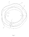
- la figure 2 montre, en perspective, une pièce d'inversion selon l'invention ; et
- la figure 3 représente, toujours en perspective, une variante de pièce d'inversion munie de lames d'absorption du jeu radial
- la figure 4 représente une variante de la configuration de la figure 2, avec un pont de rigidification ; et
- les figures 5 et 6 illustrent deux configurations possibles de la variante aux parois munies d'ouvertures.
Claims (15)
- Dispositif assurant la liaison électrique entre deux corps respectivement fixe et mobile animés d'un mouvement relatif de rotation, définissant entre eux un espace annulaire d'axe confondu avec l'axe de rotation, et présentant à cet effet deux flasques radiaux, chacun solidaire de l'une de deux parois axiales en regard respectivement intérieure et extérieure, entre lesquelles sont disposés d'une part au moins un câble plat flexible ou au moins un ensemble de fils flexibles de liaison électrique enroulé de sorte que chacune de ses extrémités soit fixée à l'une desdites parois, et d'autre part au moins une pièce de guidage apte à se déplacer relativement aux dits corps lorsque ceux-ci sont en mouvement relatif, selon une trajectoire circulaire centrée sur ledit axe de rotation, ladite pièce étant d'allure annulaire et permettant l'inversion de l'enroulement du câble ou de l'ensemble de fils flexibles par passage dans un canal d'inversion d'orientation d'allure radiale faisant varier en se déplaçant la longueur de la portion bobinée sur la paroi intérieure et celle de la portion enroulée au voisinage de la paroi extérieure, caractérisé en ce que la paroi axiale intérieure de ladite pièce est rigide alors que la paroi axiale extérieure est flexible et élastique.
- Dispositif assurant la liaison électrique entre deux corps respectivement fixe et mobile animés d'un mouvement relatif de rotation selon la revendication précédente, caractérisé en ce que la paroi axiale intérieure de la pièce d'inversion est circulaire.
- Dispositif assurant la liaison électrique entre deux corps respectivement fixe et mobile animés d'un mouvement relatif de rotation selon l'une des revendications précédentes, caractérisé en ce que la paroi axiale extérieure de la pièce d'inversion est munie d'au moins un renflement d'allure convexe.
- Dispositif assurant la liaison électrique entre deux corps respectivement fixe et mobile animés d'un mouvement relatif de rotation selon l'une quelconque des revendications précédentes, caractérisé en ce que la pièce d'inversion est creuse.
- Dispositif assurant la liaison électrique entre deux corps respectivement fixe et mobile animés d'un mouvement relatif de rotation selon l'une quelconque des revendications précédentes, caractérisé en ce que la pièce d'inversion est pleine et constituée en un matériau de type mousse dense élastique recouverte, sur sa paroi intérieure, d'un revêtement rigide.
- Dispositif assurant la liaison électrique entre deux corps respectivement fixe et mobile animés d'un mouvement relatif de rotation selon l'une quelconque des revendications 1 à 4, caractérisé en ce que l'épaisseur de la paroi intérieure rigide est supérieure à celle de la paroi extérieure souple.
- Dispositif assurant la liaison électrique entre deux corps respectivement fixe et mobile animés d'un mouvement relatif de rotation selon l'une quelconque des revendications précédentes, caractérisé en ce que les parois du canal d'inversion sont de forme sensiblement semi-circulaire, concaves et d'allure symétrique par rapport à un axe médian dudit canal.
- Dispositif assurant la liaison électrique entre deux corps respectivement fixe et mobile animés d'un mouvement relatif en rotation selon l'une quelconque des revendications précédentes, caractérisé en ce que les parois du canal d'inversion sont reliées par une patte de raccordement solidarisant leurs chants axiaux en regard.
- Dispositif assurant la liaison électrique entre deux corps respectivement fixe et mobile animés d'un mouvement relatif en rotation selon l'une quelconque des revendications précédentes, caractérisé en ce que les parois axiales extérieure et intérieure sont reliées par des nervures.
- Dispositif assurant la liaison électrique entre deux corps respectivement fixe et mobile animés d'un mouvement relatif en rotation selon l'une quelconque des revendications précédentes, caractérisé en ce qu'au moins l'une des parois axiales intérieure et extérieure présente une interruption au voisinage du canal d'inversion.
- Dispositif assurant la liaison électrique entre deux corps respectivement fixe et mobile animés d'un mouvement relatif de rotation selon l'une quelconque des revendications précédentes, caractérisé en ce que la pièce d'inversion comporte des moyens de limiter ou de supprimer le déplacement axial en direction des flasques radiaux.
- Dispositif assurant la liaison électrique entre deux corps respectivement fixe et mobile animés d'un mouvement relatif de rotation selon la revendication précédente, caractérisé en ce que lesdits moyens sont constitués de lames élastiques disposées sur au moins l'une des faces de la pièce d'inversion orientée parallèlement aux flasques radiaux.
- Dispositif assurant la liaison électrique entre deux corps respectivement fixe et mobile animés d'un mouvement relatif de rotation selon la revendication précédente, caractérisé en ce que lesdites lames sont orientées radialement ou tangentiellement à au moins l'une des parois axiales de la pièce d'inversion.
- Dispositif assurant la liaison électrique entre deux corps respectivement fixe et mobile animés d'un mouvement relatif de rotation selon l'une quelconque des revendications précédentes, caractérisé en ce que la pièce d'inversion comporte des moyens d'atténuer le bruit provoqué par son déplacement axial.
- Dispositif assurant la liaison électrique entre deux corps respectivement fixe et mobile animés d'un mouvement relatif de rotation selon la revendication précédente, caractérisé en ce que lesdits moyens consistent en un revêtement souple équipant au moins l'une des faces parallèles aux flasques de la pièce d'inversion.
Applications Claiming Priority (2)
| Application Number | Priority Date | Filing Date | Title |
|---|---|---|---|
| FR0208866A FR2842357B1 (fr) | 2002-07-12 | 2002-07-12 | Piece de guidage flexible interne a un contact tournant |
| FR0208866 | 2002-07-12 |
Publications (2)
| Publication Number | Publication Date |
|---|---|
| EP1381122A1 true EP1381122A1 (fr) | 2004-01-14 |
| EP1381122B1 EP1381122B1 (fr) | 2011-05-18 |
Family
ID=29725323
Family Applications (1)
| Application Number | Title | Priority Date | Filing Date |
|---|---|---|---|
| EP20030291636 Expired - Lifetime EP1381122B1 (fr) | 2002-07-12 | 2003-07-02 | Pièce de guidage flexible interne à un contact tournant |
Country Status (2)
| Country | Link |
|---|---|
| EP (1) | EP1381122B1 (fr) |
| FR (1) | FR2842357B1 (fr) |
Citations (5)
| Publication number | Priority date | Publication date | Assignee | Title |
|---|---|---|---|---|
| DE3931905A1 (de) * | 1988-12-01 | 1990-06-07 | Alps Electric Co Ltd | Verbindungseinrichtung in form eines nach art einer uhrfeder angeordneten flexiblen elektrischen kabels |
| EP0741058A2 (fr) * | 1995-05-02 | 1996-11-06 | Yazaki Corporation | Appareil pour établir la connexion électrique entre un rotor et une partie fixe |
| US5700153A (en) * | 1995-01-12 | 1997-12-23 | Yazki Corporation | Relay device for rotating members |
| US5772146A (en) * | 1993-12-22 | 1998-06-30 | Nihon Plast Co., Ltd. | Reel device for cable |
| US6096976A (en) * | 1995-11-09 | 2000-08-01 | Yazaki Corporation | Relay apparatus between relative rotary materials |
-
2002
- 2002-07-12 FR FR0208866A patent/FR2842357B1/fr not_active Expired - Fee Related
-
2003
- 2003-07-02 EP EP20030291636 patent/EP1381122B1/fr not_active Expired - Lifetime
Patent Citations (5)
| Publication number | Priority date | Publication date | Assignee | Title |
|---|---|---|---|---|
| DE3931905A1 (de) * | 1988-12-01 | 1990-06-07 | Alps Electric Co Ltd | Verbindungseinrichtung in form eines nach art einer uhrfeder angeordneten flexiblen elektrischen kabels |
| US5772146A (en) * | 1993-12-22 | 1998-06-30 | Nihon Plast Co., Ltd. | Reel device for cable |
| US5700153A (en) * | 1995-01-12 | 1997-12-23 | Yazki Corporation | Relay device for rotating members |
| EP0741058A2 (fr) * | 1995-05-02 | 1996-11-06 | Yazaki Corporation | Appareil pour établir la connexion électrique entre un rotor et une partie fixe |
| US6096976A (en) * | 1995-11-09 | 2000-08-01 | Yazaki Corporation | Relay apparatus between relative rotary materials |
Also Published As
| Publication number | Publication date |
|---|---|
| FR2842357B1 (fr) | 2006-08-18 |
| EP1381122B1 (fr) | 2011-05-18 |
| FR2842357A1 (fr) | 2004-01-16 |
Similar Documents
| Publication | Publication Date | Title |
|---|---|---|
| EP0464767B1 (fr) | Dispositif formé de deux éléments articulés autour d'une charnière et reliés par une liaison électrique | |
| FR2555695A1 (fr) | Derailleur avant comportant un element de protection ou capuchon pour le ressort de rappel | |
| FR2665805A1 (fr) | Dispositif de transmission de signaux electriques sans balai. | |
| FR2932926A1 (fr) | Dispositif de connexion rotatif | |
| EP1199243B1 (fr) | Système et volant de direction pour véhicule | |
| FR2797208A1 (fr) | Element antivibrations pourvu d'une surete d'arrachement | |
| EP2586119B1 (fr) | Support moteur a dispositif de limitation de mouvements | |
| FR2828723A1 (fr) | Piece de liaison de tubes pour des tubes ondules avec element d'amortissement interieur | |
| FR2738677A1 (fr) | Contacteur tournant a ruban court, notamment pour vehicules automobiles | |
| EP1381122B1 (fr) | Pièce de guidage flexible interne à un contact tournant | |
| EP1787041B1 (fr) | Agencement pour la fixation d'un mecanisme d'essuyage | |
| FR2776329A1 (fr) | Agencement pour la transmission de mouvement entre un verrou et une serrure de vehicule automobile | |
| FR2801656A1 (fr) | Mecanisme a roue d'engrenage conique et systeme de direction a puissance electrique l'utilisant | |
| FR3009048A1 (fr) | Disque d'embrayage pour embrayage a friction | |
| EP1320153A1 (fr) | Dispositif de liaison électrique entre deux corps en rotation relative | |
| EP2857710B1 (fr) | Dispositif d'amortissement comportant un organe de battement. | |
| FR2855478A1 (fr) | Composant d'equipement de vehicule automobile a points de fixation amortisseur de vibrations | |
| FR2772195A1 (fr) | Contacteur tournant a rotation limitee, notamment pour vehicule automobile | |
| FR2830673A1 (fr) | Interrupteur rotatif pour un moteur d'essuie-glace | |
| FR3120998A1 (fr) | Appareil électrique encastrable | |
| EP0680848B1 (fr) | Contacteur électrique tournant comprenant un conducteur souple de longueur limitée | |
| FR2946425A1 (fr) | Resolveur | |
| EP1324437B1 (fr) | Contact tournant à dispositif externe de tension du cable | |
| EP0753431A1 (fr) | Dispositif de rangement d'objet notamment pour véhicule automobile | |
| FR2709608A1 (fr) | Connecteur électrique rotatif. |
Legal Events
| Date | Code | Title | Description |
|---|---|---|---|
| PUAI | Public reference made under article 153(3) epc to a published international application that has entered the european phase |
Free format text: ORIGINAL CODE: 0009012 |
|
| AK | Designated contracting states |
Kind code of ref document: A1 Designated state(s): AT BE BG CH CY CZ DE DK EE ES FI FR GB GR HU IE IT LI LU MC NL PT RO SE SI SK TR |
|
| AX | Request for extension of the european patent |
Extension state: AL LT LV MK |
|
| 17P | Request for examination filed |
Effective date: 20040206 |
|
| AKX | Designation fees paid |
Designated state(s): DE FR |
|
| GRAP | Despatch of communication of intention to grant a patent |
Free format text: ORIGINAL CODE: EPIDOSNIGR1 |
|
| GRAS | Grant fee paid |
Free format text: ORIGINAL CODE: EPIDOSNIGR3 |
|
| GRAA | (expected) grant |
Free format text: ORIGINAL CODE: 0009210 |
|
| AK | Designated contracting states |
Kind code of ref document: B1 Designated state(s): DE FR |
|
| REG | Reference to a national code |
Ref country code: DE Ref legal event code: R096 Ref document number: 60337130 Country of ref document: DE Effective date: 20110630 |
|
| PLBE | No opposition filed within time limit |
Free format text: ORIGINAL CODE: 0009261 |
|
| STAA | Information on the status of an ep patent application or granted ep patent |
Free format text: STATUS: NO OPPOSITION FILED WITHIN TIME LIMIT |
|
| 26N | No opposition filed |
Effective date: 20120221 |
|
| REG | Reference to a national code |
Ref country code: DE Ref legal event code: R097 Ref document number: 60337130 Country of ref document: DE Effective date: 20120221 |
|
| REG | Reference to a national code |
Ref country code: FR Ref legal event code: PLFP Year of fee payment: 14 |
|
| PGFP | Annual fee paid to national office [announced via postgrant information from national office to epo] |
Ref country code: DE Payment date: 20160726 Year of fee payment: 14 |
|
| PGFP | Annual fee paid to national office [announced via postgrant information from national office to epo] |
Ref country code: FR Payment date: 20160726 Year of fee payment: 14 |
|
| REG | Reference to a national code |
Ref country code: DE Ref legal event code: R119 Ref document number: 60337130 Country of ref document: DE |
|
| REG | Reference to a national code |
Ref country code: FR Ref legal event code: ST Effective date: 20180330 |
|
| PG25 | Lapsed in a contracting state [announced via postgrant information from national office to epo] |
Ref country code: DE Free format text: LAPSE BECAUSE OF NON-PAYMENT OF DUE FEES Effective date: 20180201 |
|
| PG25 | Lapsed in a contracting state [announced via postgrant information from national office to epo] |
Ref country code: FR Free format text: LAPSE BECAUSE OF NON-PAYMENT OF DUE FEES Effective date: 20170731 |