EP1380995A2 - A coin sorter - Google Patents
A coin sorter Download PDFInfo
- Publication number
- EP1380995A2 EP1380995A2 EP02028862A EP02028862A EP1380995A2 EP 1380995 A2 EP1380995 A2 EP 1380995A2 EP 02028862 A EP02028862 A EP 02028862A EP 02028862 A EP02028862 A EP 02028862A EP 1380995 A2 EP1380995 A2 EP 1380995A2
- Authority
- EP
- European Patent Office
- Prior art keywords
- coin
- passageway
- magnet
- fixed
- guiding
- Prior art date
- Legal status (The legal status is an assumption and is not a legal conclusion. Google has not performed a legal analysis and makes no representation as to the accuracy of the status listed.)
- Granted
Links
Images


Classifications
-
- G—PHYSICS
- G07—CHECKING-DEVICES
- G07D—HANDLING OF COINS OR VALUABLE PAPERS, e.g. TESTING, SORTING BY DENOMINATIONS, COUNTING, DISPENSING, CHANGING OR DEPOSITING
- G07D3/00—Sorting a mixed bulk of coins into denominations
- G07D3/14—Apparatus driven under control of coin-sensing elements
-
- G—PHYSICS
- G07—CHECKING-DEVICES
- G07D—HANDLING OF COINS OR VALUABLE PAPERS, e.g. TESTING, SORTING BY DENOMINATIONS, COUNTING, DISPENSING, CHANGING OR DEPOSITING
- G07D3/00—Sorting a mixed bulk of coins into denominations
- G07D3/12—Sorting coins by means of stepped deflectors
- G07D3/121—Sorting coins by means of stepped deflectors arranged on inclined paths
- G07D3/123—Sorting coins by means of stepped deflectors arranged on inclined paths the coins being deflected off rails
- G07D3/125—Sorting coins by means of stepped deflectors arranged on inclined paths the coins being deflected off rails by moving deflectors
Definitions
- This present invention relates to an improvement of a selector which is used in a vending machine or a game machine.
- This present invention relates to a selector which distinguishes coins with magnetism. More especially this present invention relates to a selector which distinguishes coins the center section of which is made of a low magnetic material and its peripheral section is made of a non-magnetic material.
- "Coin” which is used on this specification embraces medals or tokens like a coin.
- This prior art includes a first magnet which has a low magnet and is located upstream and a second higher magnet which is located downstream. Therefore only ferromagnetic coins are changed into the direction by the first magnet, and are distinguished. A low magnetic coin doesn't gravitate by the first magnet, therefore the coin is changed to direction by the second magnet, and it is distinguished. Also, the non-magnetic coin passes through the second magnet, therefore it is distinguished.
- the prior art can distinguish a ferromagnetic coin, the low magnetic coin or the non-magnetic coin, because the magnetic coins are changed in their direction by the magnetic force of the magnet. In other words, the coins are distinguished by the magnetic force and the coin speed.
- the magnetic force can line up the fixed value.
- the low magnetic coin is distinguished to the non-magnetic coin rarity.
- the low magnetic coin doesn't change to a predetermined direction by the second magnet, and passes through.
- the purpose of this present invention is to solve the problems.
- the first purpose of the present invention is to provide the selector which can distinguish low magnetic coins.
- the second purpose of the present invention is to provide a selector which can distinguish low magnetic coins and which is inexpensive.
- the third purpose of the present invention is to provide a selector which can be easily adjusted.
- this present invention includes the following structure.
- a coin-selector of a coin with magnetism which selects either genuine or false of a coin in the process of guiding the coins through a coin passageway comprises:
- the low magnetic coin is guided by the coin passageway and tumbles down. On the way down, the coin passes through the side of the movable magnet. In this bout, the adsorbability of the magnet operates on the low magnetic coin, however the coin cannot move to the movable magnet side. Therefore the movable magnet moves towards the coin side. Also, the guiding member moves into the coin passageway in conjunction with the moving of the movable coin.
- the low magnetic coin has contact with the guiding member and is guided to a predetermined direction. As a result, the low magnetic coin is distinguished.
- the coin When the coin is the non-magnetic coin, the coin doesn't receive the adsorbability of the magnet. Therefore the non-magnetic coin doesn't move. As a result the non-magnetic coin hasn't contact with the guiding member, and is distinguished.
- the coin When the coin is a ferromagnetic coin, the coin is held by the movable magnet or by another fixed magnet at the coin passageway. Therefore the low magnetic coin is distinguished. Also, the structure is simple and is inexpensive. In this present invention, a power source isn't used.
- the present first aspect of the invention is desirable because the movable magnet and the guiding member are located at a lever which can pivot.
- the guiding member moves directly based on the moving of the movable magnet and the guiding member moves into the coin passageway. As a result, the low magnetic coin is distinguished.
- the present invention is inexpensive, because the lever has the movable magnet and the guiding member.
- the first aspect is desirable, because the fixed magnet which is located at the upstream of the movable magnet is fixed at the side of the coin passageway.
- the lever is biased as the guiding member moves to go out from the coin passageway by self moment and by the weight of the movable magnet. Therefore there is no need to add and to adjust a special biasing device.
- this aspect is desirable because the fixed magnet is located upstream of the movable magnet and is fixed at the side of the coin passageway. In this structure, the ferromagnetic coin is held by the fixed magnet. Therefore, the structure is simple, and the clearing unit for the distinguished coins is also simple too.
- a coin-selector of a coin with magnetism which selects either genuine or false coins in process of guiding the coins through the coin passageway which is located between a fixed guiding board and a movable guiding board comprises:
- the coin when a ferromagnetic coin is used, the coin is held by the magnetic of the movable magnet, therefore it is distinguished.
- the coin When a low magnetic coin is used, the coin is guided by the fixed guiding board and passes through the side of the movable magnet. Therefore the movable magnet moves towards the coin passageway side.
- the lever pivots in conjunction with movement of the movable magnet, and the guiding member moves into the coin passageway.
- the low magnetic coin impacts on the guiding member, and it changes the direction of movement, therefore it is distinguished.
- the coin doesn't move as has been previously, and it doesn't change course. As a result the coin is distinguished.
- This structure is drastically simple, therefore it is inexpensive and can be used at the area of non-electric current source.
- a third aspect of the invention includes the following structure.
- a coin-selector of a coin with magnetism which selects either genuine or false coins in process of guiding the coins through a coin passageway which is located between a fixed guiding board and a movable guiding board comprises:
- the coin when a ferromagnetic coin is used, the coin is held by the magnetic of the movable magnet, therefore it is distinguished.
- the coin When a low magnetic coin is used, the coin is guided by the fixed guiding board and passes through the side of the movable magnet. Therefore, the movable magnet moves towards the coin passageway side.
- the lever pivots in conjunction with the movement of the movable magnet, and the guiding member moves into the coin passageway.
- the low magnetic coin strikes on the guiding member, and it changes the direction of movement, therefore it is distinguished.
- a ferromagnetic coin is held by the magnetic of the movable magnet, therefore the coin is distinguished.
- this structure is drastically simple, therefore it is inexpensive and can be used in the area of a non-electric current source.
- first, second and third aspects of the invention are desirable, because also they include a stopper which limits the standby position of the lever.
- the standby position of the lever is located slightly away from the coin passageway by the stopper. Therefore, when the movable magnet slightly moves, the guiding member moves quickly into the coin passageway. As a result, the coin is distinguished.
- first, second and third aspects of the invention are desirable, because also they include an adjuster which adjusts the position of the stopper.
- an adjuster which adjusts the position of the stopper.
- a fixed guiding board 1 includes a back board 1A which is plain and vertical and has side-boards 1B, 1C.
- the side-boards 1B and 1C are bent perpendicular to the side section of the fixed guiding board 1 and are directed towards the front.
- a fixed shaft 3 is fixed perpendicular at brackets 2A, 2B which are bent horizontal towards side board 1B from side board 1C.
- the right end of the movable guide board 4 pivots at the fixed shaft 3.
- the moving guide board 4 can pivot horizontally and is urged towards the fixed side board 1 by a spring 5.
- An L section 4A of the moving guide board 4 is stopped by the back board 1A. Therefore, the distance between the back board 1A and the moving guide board 4 is slightly thicker than a coin's thickness and is parallel. Therefore, the structure of a coin passageway 6 extends perpendicular.
- a coin entry 7 is rectangle and is located near the left side board 1B.
- the entry 7A distinguishes the thickness of a coin.
- a known cradle 8 is located under the coin entry 7 and has claws 8A, 8B which are located away at predetermined distances.
- the cradle 8 can pivot on a fixed shaft 9 which is horizontal from the moving guide board 4.
- a guiding rail 10 is located under the cradle 8 to one side.
- the guiding rail 10 can slide in an elongated hole 11 of the moving guiding board 4.
- a fixed magnet 12 is a permanent magnet and is located at the side of the moving guiding board 4 and is located downstream to a guiding rail 10.
- the fixed magnet 12 is fixed at a bracket 13 which can pivot at the fixed shaft 3.
- the fixed magnet 12 is attached to the bracket 13.
- the bracket 13 is rectangular and can be moved into an opening (not shown) of the movable guide board 4 and faces the coin passageway 6.
- the bracket 13 is urged to the movable guide board 4 side by the spring 5.
- a screw 14 is screwed in at the end of the bracket 13, and it's end has contact with the moving guide board 4. Therefore, the fixed magnet 12 has a predetermined distance, because the guiding magnet 12 can adjust the distance to the coin passageway 6.
- a cancelling lever 16 can pivot on a shaft 15 which is fixed at the rear of the back board 1A.
- a pin 17 is fixed at the cancelling lever 15.
- a cam-surface is located at the inner of the moving guide board 4.
- the cancelling lever 16 is pushed downwards (in the counter clockwise direction in the figure 3)
- the pin 17 pushes to a cam-surface of the movable guide board 4. Therefore, the movable guide board 4 pivots at the fixed shaft 3 and is away from the back board 1A.
- a wiper 18 which is a lever is fixed at the shaft 15 and is located between the back board 1A and the moving guide board 4 and can move into the coin passageway 6.
- a shaft 21 is fixed at bearings 20A, 20B which are perpendicular to the back of the back board 1A side from the bracket 20 which is fixed at the rear of the back board 1A.
- Bearings 22A and 22B protrude to the back of the back board 1A side and from the middle of a lever 22 which is elongated perpendicular and can pivot on the shaft 21. Both sides of the bearings 22A and 22B are guided by the bearings 20A and 20B. Therefore, the lever 22 can not slide to the shaft 21.
- a movable magnet 24 is a cylinder and is fixed at a cross arm 22C by a screw 23.
- the cross arm 22C protrudes towards back board 1A side from a position which is lower than the shaft 21 of the lever 22.
- the movable magnet 24 is a permanent magnet and is a ferromagnet which is made from a rare earth magnet.
- the movable magnet 24 can be shaped rectangular, however the shape can be changed to a desired shape.
- a hole 25 having a circular form is located at the back board 1A opposite to the movable magnet 24.
- the movable magnet 24 is located at the coin passageway 6 side.
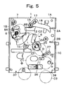
- the movable magnet 24 is located downstream to the side of the guiding rail 10 shown in figure 5. Normally, the middle of a coin passes through this position. This position is located downstream and below the fixed magnet 12.
- the lower section of the lever 22 is bent to a right angle towards the back board 1A side and is a guiding member 26.
- the guiding member 26 can move into the coin passageway 6 which passes through the bracket 20 and an opening 27 of the back board 1A.
- the guiding member 26 is rectangle and has the width which cross the coin passageway 6 and the length which is longer than the half of coin diameter.
- the width of the guiding member 26 can be narrowed in comparison with the coin passageway 6 because the width can guide the coin to the receiving passageway 37.
- the guiding member 26 is located downstream to the moving magnet 24 and is located below and at a side to the movable magnet 24.
- the guiding member 26 is approximately rectangular to a falling direction line D of the coin which afterwards is guided by the guiding rail 10. Also, when the coin falls down normally, the coin impacts on the guiding member 26. The impact point is concentrated near the moving magnet 24 rather than the center.
- the distance between the guiding member 26 and the side-board 1C is smaller than the diameter of a coin.
- the movable magnet 24 is located near the supporting point of the lever 22, and the guiding member 26 is located away from the movable magnet 24. Therefore, when the movable magnet 24 is slightly moved, the guiding member 26 moves larger than the movable magnet 24. As a result, the guiding member 26 moves into the coin passageway 26. Also, the movement of the movable magnet 24 and the guiding member 26 moves together. Therefore, the energy of the movement is reduced, and guiding member 26 moves into the coin passageway 6 quickly.
- the movable magnet 24 and the guiding member 26 can be separated. However, they are linked, and work closely together.
- a screw 31 is screwed in the upper section of the lever 22 which is located upwards towards the shaft 21, and it is locked by a lock nut 32.
- the screw 31 is a stopper.
- the screw 31 and the lock nut 32 are an adjusting device.
- the lever 22 is urged by the weight of the movable magnet 24, the guiding member 26 and the stopper 30 etc. as the guiding member 26 goes out of the coin passageway 6.
- the stopper 30 stops the movement of the back board 1A because the screw 31 has contact with the back board 1A.
- the stopper 30 has a function that the guiding member 26 holds at the position adjacent to the coin passageway 6. This position of the guiding member 26 can move into the coin passageway 6 quickly.
- the screw 33 has a brim 34 which is located in the middle. The end of the screw 33 screws into the bracket 20 and is locked by the lock nut 35. When the guiding member 26 moves into the coin passageway 6, the lever 22 is stopped by the brim 34.
- the screw 33 has a function which adjusts the projection of the guiding member 26 and a function which guides the lever 22.
- a diverter 36 is located downstream of the guiding member 26 and is located at the side of the guiding member 26. Therefore, the diverter 36 is located below the movable magnet 24 and is fixed at the back board 1A which can be adjustable to the lateral direction shown in figure 5.
- the left side of the diverter 36 is a receiving passageway 37 for a genuine coin.
- the right side of the diverter 36 is a returning passageway 38 for a false coin.
- the Euro coin is a bimetallic coin.
- the middle is circular and has a low magnetic force which is fitted in the rim.
- the rim is non-magnetic and is ring shaped. Firstly, in the case that a genuine coin is used is explained.
- the low magnetic coin 1C has gone into entry 7 and is transported towards the guiding rail 10 side by the cradle 7, afterwards it falls down.
- the fallen coin C1 is guided by the guiding rail 10 and passes through at the side of the fixed coin 12.
- the low magnetic section of the low magnetic coin C1 is pulled by the magnetic force of the fixed magnet 12 and has contact with the back board 1A and isn't held by the magnetic force and passes through there.
- the coin C1 falls to the side and downwards by gravity and by the inertia because it isn't guided by the guiding rail 10.
- the middle of the coin C1 passes through the side of the movable magnet 24.
- the coin C1 receives the magnetic pull force from the movable magnet 24 and falls down having contact with the back board 1A.
- the lever 22 pivots in the clockwise direction shown in figure 4 by self moment.
- the stopper 30 has contact with the back board 1A and is in the standby position. (shown the dotted line in figure 4).
- the movable magnet 24 moves towards the side of the coin C1. Therefore, the lever 22 pivots in the counter clockwise direction shown in figure 4.
- the guiding member 26 moves into the coin passageway 6. (shown the solid line in figure 4).
- the fallen coin C1 impacts the guiding member 26 in approximately the right angle position, and is rebounded towards the left direction from the guiding member shown in figure 5 and is guided to the receiving passageway 37 and is separated. If the rebounding is short, the rebounded coin C1 is guided by the diverter 36 and goes to the receiving passageway 37.
- the coin C2 is guided by the cradle 6 and the guiding rail 10 and arrives to the fixed magnet 12.
- the coin C2 is held by the fixed magnet 12 because the magnetic pull force to the ferromagnetic coin is large enough. Therefore, the coin C2 is kept in the coin passageway 6.
- the lever 16 is pushed down, and the guiding board 4 is pivoted, and a wiper 18 is pivoted, and the wiper 18 moves the coin C2 which is held by the fixed magnet 12. Therefore, the coin C2 falls down and is guided into the cancelling passageway and is returned.
- the movable magnet 24 is not moved because the coin C3 is non-magnetic. Therefore, the guiding member 26 doesn't move into the coin passageway 6. As a result, the coin C3 falls down in the returning passageway 38 and is returned.
- the low magnetic coin C1 has contact with the back board 1A by the fixed magnet 12. Afterwards, the coin C1 arrives to the side of the movable magnet 24. As a result, the distance between the coin C1 and the movable magnet 24 is constant. Therefore, the movement of the movable magnet 24 by the low magnetic coin 1C is constant every time.
- This invention can be changed.
- the fixed magnet 12 isn't used, the movable magnet 12 doubles it's function.
- the movable magnet 24 due to its magnetic force pulls the ferromagnetic coin and holds it, and the ferromagnetic coin is held in the coin passageway 6.
- this invention can be used to a full low magnetic coin and to a coin where the middle is made of non-magnetic material and the rim is made of a low magnetic material.
Landscapes
- Physics & Mathematics (AREA)
- General Physics & Mathematics (AREA)
- Testing Of Coins (AREA)
- Control Of Vending Devices And Auxiliary Devices For Vending Devices (AREA)
Abstract
Description
This structure is drastically simple, therefore it is inexpensive and can be used at the area of non-electric current source.
The
This position of the guiding
Claims (8)
- A coin-selector of a coin with magnetism which selects either genuine or false coins in the process of guiding the coin through a coin passageway (6) comprising:a movable magnet (24) which moves at the side of the coin passageway (6),a guiding member (26) which moves into the passageway (6) in conjunction with the movement of the movable magnet (24).
- The coin-selector of a coin with magnetism as claimed in claim 1, wherein the movable magnet (24) and the guiding member (26) are located at a lever (22) which can pivot.
- The coin-selector of a coin with magnetism as claimed in claim 2, wherein the lever (22) is biased to go out from the coin passageway (6) by the self-moment.
- The coin-selector of a coin with magnetism as claimed in claim 1, 2 or 3, wherein a fixed magnet (12) which is located at the upstream of the movable magnet (24) and is fixed at the side of the coin passageway (6).
- A coin-selector of a coin with magnetism which selects genuine or false coins in the process of guiding the coin through a coin passageway (6) which is located between a fixed guiding board (1) and a movable guiding board (4) comprising:a lever (22) which can pivot at the fixed guiding board (1),a movable magnet (24) which is fixed at the lever (22) and is located at the side of the coin passageway (6),a guiding member (26) which is fixed at the lever (22) which can go either in or out of the coin passageway (6) of the downstream of the movable magnet (24).
- A coin-selector of a coin with magnetism in the process of guiding the coin through the coin passageway (6) which is located between a fixed guiding board (1) and a movable guiding board (4) comprising:a fixed magnet (12) which is located at the side of the coin passageway (6),a lever (22) which can pivot at the fixed guiding board (1),a movable magnet (24) which is fixed at the lever (22) and is located at the side of the coin passageway (6) of the downstream of the fixed magnet (12),a guiding member (26) which is fixed at the lever (22) and which can go either in or out of the coin passageway (6) of the downstream of the movable magnet (24).
- The coin-selector of a coin with magnetism as claimed in claim 2, 5 or 6,also including a stopper (30) which limits the standby position of the lever (22).
- The coin-selector of a coin with magnetism as claimed in claim 7, also including an adjuster (31,32) which adjusts the position of the stopper (30).
Applications Claiming Priority (2)
| Application Number | Priority Date | Filing Date | Title |
|---|---|---|---|
| JP2001400683 | 2001-12-28 | ||
| JP2001400683A JP4048263B2 (en) | 2001-12-28 | 2001-12-28 | Coin selector for magnetic coins |
Publications (3)
| Publication Number | Publication Date |
|---|---|
| EP1380995A2 true EP1380995A2 (en) | 2004-01-14 |
| EP1380995A3 EP1380995A3 (en) | 2005-08-10 |
| EP1380995B1 EP1380995B1 (en) | 2013-05-22 |
Family
ID=27605119
Family Applications (1)
| Application Number | Title | Priority Date | Filing Date |
|---|---|---|---|
| EP20020028862 Expired - Lifetime EP1380995B1 (en) | 2001-12-28 | 2002-12-23 | A coin sorter |
Country Status (3)
| Country | Link |
|---|---|
| EP (1) | EP1380995B1 (en) |
| JP (1) | JP4048263B2 (en) |
| ES (1) | ES2425554T3 (en) |
Cited By (1)
| Publication number | Priority date | Publication date | Assignee | Title |
|---|---|---|---|---|
| EP2040226A3 (en) * | 2007-09-20 | 2009-10-21 | National Rejectors, Inc. GmbH | Coin sorting apparatus |
Families Citing this family (2)
| Publication number | Priority date | Publication date | Assignee | Title |
|---|---|---|---|---|
| JP5309965B2 (en) * | 2008-09-17 | 2013-10-09 | 旭精工株式会社 | Value medium processing device |
| JP5481637B2 (en) * | 2010-01-12 | 2014-04-23 | 旭精工株式会社 | Coin sorting machine |
Family Cites Families (2)
| Publication number | Priority date | Publication date | Assignee | Title |
|---|---|---|---|---|
| US1907064A (en) * | 1930-06-24 | 1933-05-02 | Sanitary Postage Service Corp | Coin selecting apparatus |
| US3452849A (en) * | 1967-05-31 | 1969-07-01 | Wilson M Stewart | Magnetic coin tester |
-
2001
- 2001-12-28 JP JP2001400683A patent/JP4048263B2/en not_active Expired - Fee Related
-
2002
- 2002-12-23 EP EP20020028862 patent/EP1380995B1/en not_active Expired - Lifetime
- 2002-12-23 ES ES02028862T patent/ES2425554T3/en not_active Expired - Lifetime
Cited By (1)
| Publication number | Priority date | Publication date | Assignee | Title |
|---|---|---|---|---|
| EP2040226A3 (en) * | 2007-09-20 | 2009-10-21 | National Rejectors, Inc. GmbH | Coin sorting apparatus |
Also Published As
| Publication number | Publication date |
|---|---|
| JP4048263B2 (en) | 2008-02-20 |
| JP2003196702A (en) | 2003-07-11 |
| EP1380995B1 (en) | 2013-05-22 |
| EP1380995A3 (en) | 2005-08-10 |
| ES2425554T3 (en) | 2013-10-16 |
Similar Documents
| Publication | Publication Date | Title |
|---|---|---|
| US5007519A (en) | Coin drop construction | |
| EP1380995B1 (en) | A coin sorter | |
| US8322506B2 (en) | Reeding detection apparatus and coin sorting apparatus having the same | |
| EP0560830B1 (en) | Coin guiding device | |
| US4881630A (en) | Coin discriminating apparatus | |
| US6866574B2 (en) | Apparatus for selectively dispensing discs | |
| JP5066674B2 (en) | Coin selector | |
| JP4613288B2 (en) | Weakly magnetic bimetal coin selector | |
| JP4134339B2 (en) | Bimetal coin selector | |
| US4534459A (en) | Low power coin routing gate apparatus | |
| JP2008117072A5 (en) | ||
| JP5568802B2 (en) | Coin sorting machine | |
| JP2007310557A (en) | Coin selector | |
| EP1548656A1 (en) | A low force coin dispensing apparatus | |
| JP5481637B2 (en) | Coin sorting machine | |
| JP2001229431A (en) | Rolling coin selector | |
| JPH0749583Y2 (en) | Structure of coin input passage | |
| JPH0418058Y2 (en) | ||
| JP2004310604A (en) | Coin canceling device for coin sorting device | |
| JP3695926B2 (en) | Coin sorting machine | |
| GB2097165A (en) | Coin handling mechanism | |
| KR19980064099A (en) | Coin sorting device | |
| JP2014041409A (en) | Holding device for a plurality of kinds of coins, and selection device for a plurality of kinds of coins having holding device for a plurality of kinds of coins | |
| JPH10172020A (en) | Coin sorting equipment | |
| JP2013105296A5 (en) |
Legal Events
| Date | Code | Title | Description |
|---|---|---|---|
| PUAI | Public reference made under article 153(3) epc to a published international application that has entered the european phase |
Free format text: ORIGINAL CODE: 0009012 |
|
| AK | Designated contracting states |
Kind code of ref document: A2 Designated state(s): AT BE BG CH CY CZ DE DK EE ES FI FR GB GR IE IT LI LU MC NL PT SE SI SK TR |
|
| AX | Request for extension of the european patent |
Extension state: AL LT LV MK RO |
|
| PUAL | Search report despatched |
Free format text: ORIGINAL CODE: 0009013 |
|
| AK | Designated contracting states |
Kind code of ref document: A3 Designated state(s): AT BE BG CH CY CZ DE DK EE ES FI FR GB GR IE IT LI LU MC NL PT SE SI SK TR |
|
| AX | Request for extension of the european patent |
Extension state: AL LT LV MK RO |
|
| 17P | Request for examination filed |
Effective date: 20050721 |
|
| AKX | Designation fees paid | ||
| RBV | Designated contracting states (corrected) |
Designated state(s): DE ES GB IT NL |
|
| GRAP | Despatch of communication of intention to grant a patent |
Free format text: ORIGINAL CODE: EPIDOSNIGR1 |
|
| GRAS | Grant fee paid |
Free format text: ORIGINAL CODE: EPIDOSNIGR3 |
|
| GRAA | (expected) grant |
Free format text: ORIGINAL CODE: 0009210 |
|
| AK | Designated contracting states |
Kind code of ref document: B1 Designated state(s): DE ES GB IT NL |
|
| REG | Reference to a national code |
Ref country code: GB Ref legal event code: FG4D |
|
| REG | Reference to a national code |
Ref country code: DE Ref legal event code: R096 Ref document number: 60244983 Country of ref document: DE Effective date: 20130718 |
|
| REG | Reference to a national code |
Ref country code: NL Ref legal event code: T3 |
|
| REG | Reference to a national code |
Ref country code: ES Ref legal event code: FG2A Ref document number: 2425554 Country of ref document: ES Kind code of ref document: T3 Effective date: 20131016 |
|
| PLBE | No opposition filed within time limit |
Free format text: ORIGINAL CODE: 0009261 |
|
| STAA | Information on the status of an ep patent application or granted ep patent |
Free format text: STATUS: NO OPPOSITION FILED WITHIN TIME LIMIT |
|
| 26N | No opposition filed |
Effective date: 20140225 |
|
| REG | Reference to a national code |
Ref country code: DE Ref legal event code: R097 Ref document number: 60244983 Country of ref document: DE Effective date: 20140225 |
|
| PGFP | Annual fee paid to national office [announced via postgrant information from national office to epo] |
Ref country code: DE Payment date: 20141211 Year of fee payment: 13 Ref country code: GB Payment date: 20141219 Year of fee payment: 13 Ref country code: ES Payment date: 20141226 Year of fee payment: 13 |
|
| PGFP | Annual fee paid to national office [announced via postgrant information from national office to epo] |
Ref country code: NL Payment date: 20141219 Year of fee payment: 13 |
|
| PGFP | Annual fee paid to national office [announced via postgrant information from national office to epo] |
Ref country code: IT Payment date: 20141219 Year of fee payment: 13 |
|
| REG | Reference to a national code |
Ref country code: DE Ref legal event code: R119 Ref document number: 60244983 Country of ref document: DE |
|
| GBPC | Gb: european patent ceased through non-payment of renewal fee |
Effective date: 20151223 |
|
| REG | Reference to a national code |
Ref country code: NL Ref legal event code: MM Effective date: 20160101 |
|
| PG25 | Lapsed in a contracting state [announced via postgrant information from national office to epo] |
Ref country code: GB Free format text: LAPSE BECAUSE OF NON-PAYMENT OF DUE FEES Effective date: 20151223 Ref country code: NL Free format text: LAPSE BECAUSE OF NON-PAYMENT OF DUE FEES Effective date: 20160101 Ref country code: DE Free format text: LAPSE BECAUSE OF NON-PAYMENT OF DUE FEES Effective date: 20160701 |
|
| PG25 | Lapsed in a contracting state [announced via postgrant information from national office to epo] |
Ref country code: IT Free format text: LAPSE BECAUSE OF NON-PAYMENT OF DUE FEES Effective date: 20151223 |
|
| REG | Reference to a national code |
Ref country code: ES Ref legal event code: FD2A Effective date: 20170127 |
|
| PG25 | Lapsed in a contracting state [announced via postgrant information from national office to epo] |
Ref country code: ES Free format text: LAPSE BECAUSE OF NON-PAYMENT OF DUE FEES Effective date: 20151224 |