EP1380490A2 - Vehicle operation control method and vehicle operation control apparatus - Google Patents
Vehicle operation control method and vehicle operation control apparatus Download PDFInfo
- Publication number
- EP1380490A2 EP1380490A2 EP03015802A EP03015802A EP1380490A2 EP 1380490 A2 EP1380490 A2 EP 1380490A2 EP 03015802 A EP03015802 A EP 03015802A EP 03015802 A EP03015802 A EP 03015802A EP 1380490 A2 EP1380490 A2 EP 1380490A2
- Authority
- EP
- European Patent Office
- Prior art keywords
- steering angle
- steering
- angle
- steering wheel
- vehicle
- Prior art date
- Legal status (The legal status is an assumption and is not a legal conclusion. Google has not performed a legal analysis and makes no representation as to the accuracy of the status listed.)
- Withdrawn
Links
Images


Classifications
-
- B—PERFORMING OPERATIONS; TRANSPORTING
- B62—LAND VEHICLES FOR TRAVELLING OTHERWISE THAN ON RAILS
- B62D—MOTOR VEHICLES; TRAILERS
- B62D5/00—Power-assisted or power-driven steering
- B62D5/008—Changing the transfer ratio between the steering wheel and the steering gear by variable supply of energy, e.g. by using a superposition gear
-
- B—PERFORMING OPERATIONS; TRANSPORTING
- B62—LAND VEHICLES FOR TRAVELLING OTHERWISE THAN ON RAILS
- B62D—MOTOR VEHICLES; TRAILERS
- B62D6/00—Arrangements for automatically controlling steering depending on driving conditions sensed and responded to, e.g. control circuits
- B62D6/002—Arrangements for automatically controlling steering depending on driving conditions sensed and responded to, e.g. control circuits computing target steering angles for front or rear wheels
-
- B—PERFORMING OPERATIONS; TRANSPORTING
- B62—LAND VEHICLES FOR TRAVELLING OTHERWISE THAN ON RAILS
- B62D—MOTOR VEHICLES; TRAILERS
- B62D6/00—Arrangements for automatically controlling steering depending on driving conditions sensed and responded to, e.g. control circuits
- B62D6/02—Arrangements for automatically controlling steering depending on driving conditions sensed and responded to, e.g. control circuits responsive only to vehicle speed
Definitions
- the present invention relates to a vehicle operation control method and vehicle operation control apparatus for controlling an actual steering angle of a driven wheel based on a steering angle of a steering wheel and vehicle velocity.
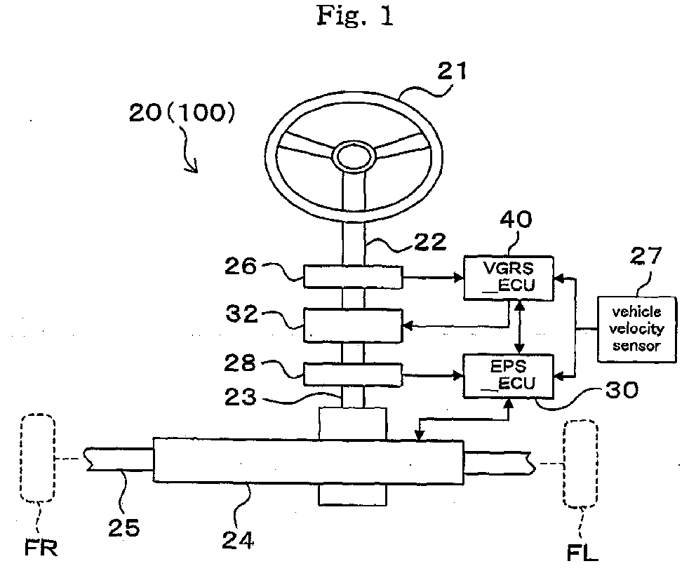
- a vehicle operation control apparatus including a transmission ratio changing mechanism for changing the transmission ratio by driving a motor, provided halfway of a steering transmission system which connects a steering wheel to driven wheels, a vehicle operation control apparatus 100 which comprises a steering wheel 21, a first steering shaft 22, a second steering shaft 23, an EPS actuator 24. a rod 25, a steering angle sensor 26, a vehicle velocity sensor 27, a torque sensor 28, an EPS ECU 30, a gear ratio changing mechanism 32 (transmission ratio changing mechanism), a VGRS ECU 40 and the like, as shown in Fig. 1, is available.
- variable gear ratio system a transmission ratio changing mechanism for changing a transmission ratio by driving an electric motor, located halfway of a steering transmission system which connects the steering wheel to the driven wheels
- VGRS variable gear ratio system
- an end of the first steering shaft 22 is connected to the steering wheel 21 and an input side of the gear ratio changing mechanism 32 is connected to the other end side of this first steering shaft 22.
- This gear ratio changing mechanism 32 comprises a motor, a reduction gear and the like.
- An end side of the second steering shaft 23 is connected to this output side of the gear ratio changing mechanism and an input side of the EPS actuator 24 is connected to the other end side of the second steering shaft 23.
- the EPS actuator 24 is an electric type powered steering system, which is capable of converting a rotary motion inputted by the second steering shaft 23 through a rack and pinion gear (not shown) to a motion in the axial direction of the rod 25 and outputting it. Further, this EPS actuator 24 generates an assist force depending on a steering condition by means of an assist motor which is controlled by the EPS ECU 30 so as to assist steering by a driver. In the meantime, this rod 25 is mounted on driven wheels FR, FL.
- a rotation angle (steering angle) of the first steering shaft 22 is detected by a steering angle sensor 26 and inputted to the VGRS ECU 40 as a steering angle signal.
- a steering torque by the second steering shaft 23 is detected by a torque sensor 28 and inputted to the EPS ECU 30 as a torque signal.
- a vehicle velocity is detected by a vehicle velocity sensor 27 and inputted to the EPS ECU 30 and VGRS ECU 40 as a vehicle velocity signal.
- the EPS actuator 24 contains a tire angle sensor (not shown) capable of detecting a tire angle (actual steering angle) from a moving amount of the rod 25.
- ratio between input gear and output gear is changed depending on vehicle velocity at real time by means of a motor and reduction gear in the gear ratio changing mechanism 32 and VGRS ECU 40 so as to change a ratio of output angle of the second steering shaft 23 relative to the steering angle of the first steering shaft 22.
- the EPS actuator 24 and the EPS ECU 30 generate an assist force for assisting steering of the vehicle driver by means of an assist motor depending on vehicle driver's steering condition and vehicle velocity detected by means of the torque sensor 28 and the vehicle velocity sensor 27.
- the steering gear ratio corresponding to the vehicle velocity can be set.
- an output angle to a second steering shaft 23 by the gear ratio changing mechanism 32 can be set to be increased with respect to the steering angle of the steering wheel at the time of vehicle stop or traveling at a low velocity.
- the output angle of the gear ratio changing mechanism 32 can be set to be decreased with respect to the steering angle of the steering wheel at the time of traveling at a high velocity.
- an appropriate assist force corresponding to the vehicle velocity can be generated by means of an assist motor.
- the steering gear ratio by the gear ratio changing mechanism 32 is set low and an assist force is intensified by an assist motor, so that the driven wheels can be steered largely even with a light steering operation.
- the assist force by the assist motor drops and the steering ratio by the gear ratio changing mechanism 32 is set high. Consequently, the steering operation becomes heavy and even if the steering wheel 21 is turned largely, it comes that the driven wheels are steered a little. Consequently, it can be expected that vehicle control stability is further improved.
- Such a vehicle operation control apparatus 100 changes the steering gear ratio corresponding to the vehicle velocity as described above.
- the steering gear ratio is changed corresponding thereto. That is, under-steer or over-steer sometimes occurs although the steering wheel is maintained at a specific angle by the vehicle driver, thereby possibly providing the vehicle driver with a feeling of disharmony.
- an object of the present invention is to provide a vehicle operation control method and vehicle operation control apparatus which protects a vehicle driver from a feeling of disharmony in his steering operation.
- a vehicle operation control method for controlling an actual steering angle of driven wheels based on a steering angle of a steering wheel and a vehicle velocity comprising:
- a vehicle operation control apparatus for controlling an actual steering angle of driven wheels based on a steering angle of a steering wheel and a vehicle velocity, comprising:
- the variable gain controlled based on a vehicle velocity is multiplied with a change amount in the steering angle, the multiplication results are integrated and then, an actual steering angle of driven wheels is controlled based on the integration result. Consequently, because if the steering angle by the steering wheel changes, a change amount in the steering angle is generated corresponding to that change, the change amount is multiplied with the variable gain controlled based on the vehicle velocity.
- the actual steering angle of the driven wheel is controlled based on the integration result integrated the multiplication results. That is, the actual steering angle of the driven wheel can be controlled based on the steering angle and the vehicle velocity.
- a transmission ratio changing machanism for changing a transmission ratio by a drive of a motor is provided halfway of a steering transmission system connecting the steering wheel with the driven wheels, the variable gain controlled in the second step being a transmission ratio attained by the transmission ratio changing mechanism.
- a transmission ratio changing mechanism for changing a transmission ratio by a drive of a motor is provided halfway of a steering transmission system connecting the steering wheel with the driven wheels, the variable gain controlled by the variable gain control means being a transmission ratio attained by the transmission ratio changing mechanism.
- a transmission ratio changing mechanism for changing the transmission ratio by a drive of a motor is provided halfway of steering transmission system which connects the steering wheel with the driven wheels, the transmission ratio is controlled based on the vehicle velocity, and this transmission ratio is multiplied with the change amount in the steering angle. Further, the multiplication results are integrated and the actual steering angle of the driven wheel is controlled based on the integration result. Consequently, because if the steering angle by the steering wheel changes, a change amount in the steering angle is generated corresponding to that change, the change amount is multiplied with the transmission ratio of the transmission ratio changing mechanism controlled based on the vehicle velocity. The actual steering angle of the driven wheel is controlled based on the integration result integrated the multiplication results.
- the actual steering angle of the driven wheel can be controlled based on the steering angle and the vehicle velocity.
- the change amount in the steering angle becomes zero when the steering wheel is maintained at a specific angle
- a result of multiplication with the transmission ratio of the transmission ratio changing mechanism also becomes zero.
- a result of integration of the multiplication results does not change when the steering wheel is maintained at a specific angle, no changes occur in the actual steering angle of the driven wheels controlled based on the integration result.
- a vehicle operation control method for controlling an actual steering angle of driven wheels based on a steering angle of a steering wheel and a vehicle velocity wherein if information that the steering wheel is not being turned or information that the steering wheel is being turned without affecting the steering of the driven wheels is obtained based on the change amount in the steering angle by the steering wheel, changes in the actual steering angle of the driven wheels is restricted.
- a vehicle operation control apparatus for controlling an actual steering angle of driven wheels based on a steering angle of a steering wheel and a vehicle velocity, further comprising a control means which if information that the steering wheel is not being turned or information that the steering wheel is being turned without affecting the steering of the driven wheels is obtained based on the change amount in the steering angle by the steering wheel, restricts changes in the actual steering angle of the driven wheels.
- the present invention if information that the steering wheel is not being turned or information that the steering wheel is being turned without affecting the steering of the driven wheels is obtained based on the change amount in the steering angle by the steering wheel, changes in the actual steering angle of the driven wheels is restricted.
- the actual steering angle of the driven wheels is controlled based on the steering angle by the steering wheel and the vehicle velocity, changes in the actual steering angle of the driven wheels is restricted. Consequently, even if the vehicle velocity changes when the steering wheel is maintained at a specific angle, the actual steering angle of the driven wheels is not affected.
- a vehicle operation control apparatus 20 comprises a steering wheel 21, a first steering shaft 22, a second steering shaft 23, an EPS actuator 24, a rod 25, a steering angle sensor 26, a vehicle velocity sensor 27, a torque sensor 28, an EPS ECU 30, a gear ratio changing mechanism 32, a VGRS ECU 40 and the like. Because its mechanical and electrical connections have been already described, description thereof is omitted here.
- Fig. 2 shows a functional block diagram showing vehicle operation control processing by means of the EPS ECU 30 and VGRS ECU 40 of the vehicle operation control apparatus 20 of this embodiment.
- the vehicle operation control apparatus 20 has a function for controlling the steering gear ratio by means of the gear ratio changing mechanism 32 according to VGRS control processing 40a with the VGRS ECU 40, depending on the vehicle velocity. Further, it has a function of assisting steering by the vehicle driver by generating an assist force depending on steering condition by means of the EPS control processing 30a with the EPS ECU 30.
- ECU electronice control unit
- a rotation angle instruction value of the motor 32m of the gear ratio changing mechanism 32 which is automatically determined corresponding to the vehicle velocity, is determined from a motor rotation angle map (not shown) when the steering angle signal by the steering angle sensor 26 and the vehicle velocity signal by the vehicle velocity sensor 27 are inputted to the VGRS ECU 40. Then, a motor voltage corresponding to the determined rotation angle instruction value is supplied to the motor 32m through a motor drive circuit.
- the gear ratio changing mechanism 32 and the VGRS ECU 40 change a ratio of an output gear to an input gear by means of the motor 32m and the reduction gear 32g corresponding to the vehicle velocity at real time, so that a ratio Gv of an output angle of the second steering shaft 23 to a steering angle of the first steering shaft 22 is changed.
- EPS control processing 30a if a steering torque signal by the torque sensor 28 and a vehicle velocity signal by the vehicle velocity sensor 27 are inputted to the EPS ECU 30, a current instruction value of the assist motor 24m of the EPS actuator 24, which is automatically determined depending upon the vehicle velocity, is determined from a motor current map (not shown). A motor voltage corresponding to the determined current instruction value is supplied to the motor 24m by the motor drive circuit. Consequently, the EPS actuator 24 and the EPS ECU 30 generate an assist force for assisting steering of a vehicle driver by means of the assist motor 24m, corresponding to the steering condition by the vehicle driver and vehicle velocity detected by the torque sensor 28 and the vehicle velocity sensor 27 through the EPS control processing 30a.
- the VGRS ECU 40 carries out the VGRS control processing 40a based on a steering angle signal transmitted from the steering angle sensor 26, so that a steering gear ratio is changed corresponding to the vehicle velocity.
- a steering gear ratio can be changed corresponding thereto.
- the vehicle operation control processing shown in Fig. 3 will be described.
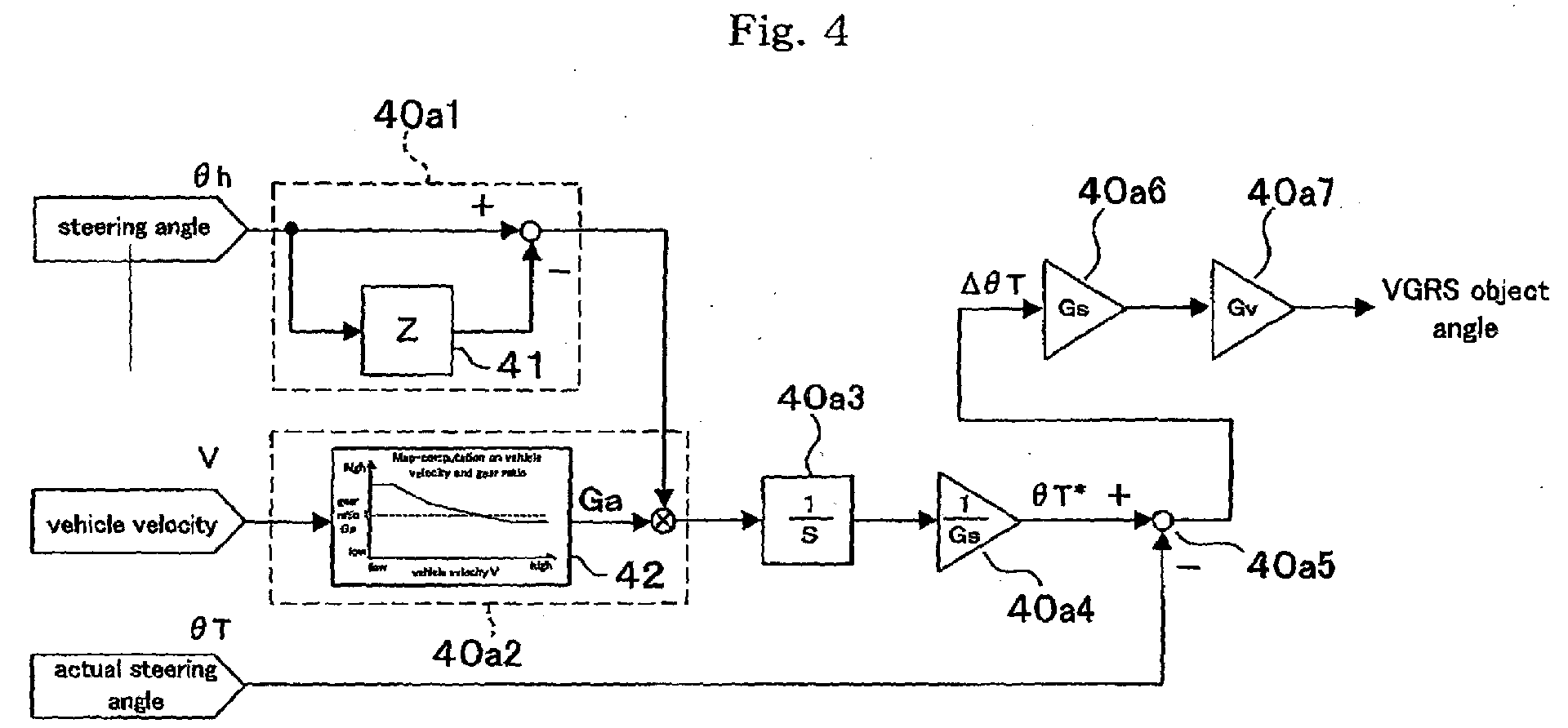
- the vehicle operation control processing by the VGRS ECU 40 is constituted of a steering angle change amount detecting means 40a1, a variable gain multiplying means 40a2, an integrating means 40a3 , an object actual steering angle computing means 40a4, a deflection amount detecting means 40a5, an object steering angle computing means 40a6, and a VGRS object angle computing means 40a7.
- a change amount ⁇ h (differential value) of the steering angle ⁇ h by the steering wheel 21 is detected by the steering angle change amount detecting means 40a1, the variable gain G is controlled by the variable gain multiplying means 4042 based on the vehicle velocity V by vehicle velocity sensor 27 and that controlled variable gain G is multiplied with the change amount ⁇ h in the steering angle. Then, the multiplication result is integrated by the integrating means 40a3 and further, that integration result (integrated value) is converted to the object actual steering angle ⁇ T* by the object actual steering angle computing means 40a4.
- the deflection amount detecting means 40a5 obtains a deflection between an actual steering angle ⁇ T by a tire angle sensor (not shown) obtained through the EPS ECU 30 and an object actual steering angle produced by conversion by the object actual steering angle computing means 40a4 so as to compute an angle deflection ⁇ T.
- the angle deflection ⁇ T is converted to an object steering angle by the object steering angle computing means 40a6 and further, converted to a VGRS object angle by the VGRS object angle computing means 40a7 so as to obtain the VGRS object angle which is outputted to the gear ratio changing mechanism 32 based on this object steering angle.
- the Gs shown in Fig. 3 indicates steering gear ratio, which is a ratio between the steering angle ⁇ h and the actual steering angle ⁇ T and Gv indicates a gear ratio of the reduction gear 32g, which is accommodated in the gear ratio changing mechanism 32.
- a rotation in the steering wheel 21, which does not affect steering of the driven wheels, that is, "a play in the steering wheel 21” may occur due to backlash or the like generated in gears constituting the gear ratio changing mechanism 32 or a steering transmission mechanism among the steering wheel 21, the first steering shaft 22 and the gear ratio changing mechanism 32. Because the change amount in the steering angle ⁇ h due to the "a play in the steering wheel 21" does not affect the steering, that change amount ⁇ h is adjusted to zero by removing it by non-sensitive range processing or filter processing, which will be described later.
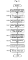
- the vehicle operation control processing is computed by the VGRS ECU 40 through the VGRS control processing 40a and respective processings of step S101-step S117 are executed successively.
- this vehicle operation control processing is carried out periodically and repeatedly by timer interruption or the like (for example, every 5 millisecond).
- timer interruption or the like for example, every 5 millisecond.
- a processing for obtaining the steering angle ⁇ h, the vehicle velocity V and the actual steering angle ⁇ T is carried out.
- the steering angle ⁇ h is obtained by receiving a steering angle signal detected by the steering angle sensor 26 from the steering angle sensor 26 or other ECU.
- the vehicle velocity V is obtained by receiving a vehicle velocity signal detected by the vehicle velocity sensor 27 from the vehicle velocity sensor 27 or the like.
- the actual steering angle ⁇ T is obtained by receiving an actual steering angle signal detected by the tire angle sensor accommodated in the EPS actuator 24 through the EPS ECU 30.
- a processing of detecting the change amount ⁇ h in steering angle ⁇ h is carried out. That is, a steering angle Z detected previously and stored in the steering angle memory 41 is subtracted from the steering angle ⁇ h obtained in step S101 through arithmetic operating processing by the steering angle change amount detecting means 40a1 shown in Fig. 4 so as to obtain a deflection between the both. Because consequently, the change amount ⁇ h in steering angle ⁇ h, that is, a differential value of the steering angle ⁇ h is computed, the change amount ⁇ h in steering angle ⁇ h is detected.
- the steering angle memory 41 is constituted of, for example, a semiconductor storage unit of the VGRS ECU 40.
- the steering angle change amount detecting means 40a1 regards the change amount in the steering angle ⁇ h by the "play in the steering wheel 21" as zero and detects the change amount ⁇ h in steering angle ⁇ h which exceeds the "play in the steering wheel 21".
- the variable gain multiplying means 40a2 shown in Fig. 4 determines a gear ratio Ga (transmission ratio by the transmission ratio changing mechanism) corresponding to the vehicle velocity V according to the vehicle velocity-gear ratio map 42, which automatically determines a transmission ratio by the gear ratio changing mechanism 32 based on the vehicle velocity V obtained in step S101.
- the vehicle velocity-gear ratio map 42 is constituted of a data table stored by the semiconductor storage unit of the VGRS ECU 40, for example.
- a processing of computing the object actual steering angle is carried out. That is, by integrating multiplication results by the integrating means 40a3 shown in FIG. 4 and then dividing that integration result by the steering gear ratio Gs by means of the object actual steering angle computing means 40a4, an object actual steering angle ⁇ T* corresponding to a change in the steering angle ⁇ h by the steering wheel 21 is obtained.
- a processing of computing a deflection between the object actual steering angle ⁇ T* and the actual steering angle ⁇ T is carried out. That is, by subtracting an actual angle ⁇ T obtained in step S101 from an object actual steering angle ⁇ T* by means of the deflection amount detecting means 40a5 shown in Fig. 4 through arithmetic operation, the deflection of the actual angle ⁇ T to the object actual steering angle ⁇ T*, that is, the angle deflection ⁇ T, is obtained.
- a processing of computing an object steering angle is carried out. That is, by multiplying the steering gear ratio Gs with the angle deflection ⁇ T obtained in step S111 by means of the object steering angle computing means 40a6 shown in Fig. 4 through arithmetic operation, the actual steering angle is converted to the steering angle, thereby obtaining the object steering angle.
- a processing of computing a VGRS object angle is carried out. That is, by multiplying the object steering angle obtained in step S113 with the gear ratio Gv of the reduction gear 32g in the gear ratio changing mechanism 32 by means of the VGRS object angle computing means 40a7 shown in FIG. 4 through arithmetic operation, the steering angle is converted to the VGRS object angle, thereby obtaining the VGRS object angle.
- a processing of memorizing the steering angle ⁇ h is carried out. That is, due to a necessity of referring to the steering angle ⁇ h obtained in step S101 as a steering angle Z detected last upon a next processing of step S103, a currently obtained steering angle ⁇ h is stored in the steering angle memory 41, so that the steering angle ⁇ h is memorized.
- the vehicle operation control apparatus 20 By executing a sequence of the vehicle operation control processing from step S101 to step S117, the vehicle operation control apparatus 20 detects a change amount ⁇ ⁇ h in the steering angle of the steering wheel 21 in step S103, controls the vehicle velocity - gear ratio map 42 (variable gain G) based on the vehicle velocity V in step S105, multiplies the change amount ⁇ h in the steering angle with a gear ratio (variable gain G) outputted according to the vehicle velocity - gear ratio map42 in step S107, integrates multiplication results in step S109, and controls the actual steering angle ⁇ T of the driven wheels FR, FL based on a result of integration in step S111.
- a gear ratio (variable gain G) from the vehicle velocity - gear ratio map 42 controlled based on the vehicle velocity V is multiplied with the change amount ⁇ h in the steering angle, the multiplication results are integrated and the actual angle ⁇ T of the driven wheels FR, FL is controlled based on the integration result.
- the gear ratio (variable gain G) controlled based on the vehicle velocity V is multiplied with the change amount ⁇ h, so that the actual steering angle ⁇ T of the driven wheels FR, FL is controlled based on an integration result of the multiplication results. That is, the actual steering angle ⁇ T of the driven wheels FR, FL can be controlled based on the steering angle ⁇ h and the vehicle velocity V.
- the change amount ⁇ h in the steering angle ⁇ h becomes zero and therefore, a result of multiplication of the variable gain G also becomes zero.
- the integration result of the multiplication results is never changed when the steering wheel 21 is maintained at a specific angle, no change occurs in the actual steering angle ⁇ T of the driven wheels FR, FL controlled based on the integration result. Therefore, even if the vehicle velocity V changes in the condition that the steering wheel 21 is maintained, the actual steering angle ⁇ T of the driven wheels FR, FL is never affected. Therefore, the over-steer characteristic and under-steer characteristic due to a sudden change in vehicle velocity can be controlled preferably, thereby protecting the vehicle driver from a feeling of disharmony.
- the step S103 may be a processing of obtaining steering angle velocity ⁇ h obtained by time-differentiating the steering angle ⁇ h.
- the steering angle velocity ⁇ h when the steering angle velocity ⁇ h is zero may correspond to "information that the steering wheel is not being turned” and the steering angle velocity ⁇ h when the steering angle velocity ⁇ h is substantially zero may correspond to "information that the steering wheel 21 is being turned without affecting the steering operation of the driven wheels" (that is, a rotation within "a play in the steering wheel 21").
- This invention provides a vehicle operation control method and vehicle operation control apparatus which protects a vehicle driver from a feeling of disharmony in his steering operation.
- a change amount ⁇ h in steering angle ⁇ h by a steering wheel is detected by means of a steering angle change amount detecting means 40a1, a variable gain G is controlled based on a vehicle velocity V by a variable gain multiplying means 40a2 and then, that controlled variable gain G is multiplied with the change amount ⁇ h in the steering angle. Then, that multiplication result is integrated by an integrating means 40a3 and the integration result is converted to an object actual steering angle by an object actual steering angle computing means 40a4.
- a deflection amount detecting means 40a5 obtains a deflection between the actual steering angle ⁇ T and the object actual steering angle ⁇ T* so as to compute an angle deflection ⁇ T.
Landscapes
- Engineering & Computer Science (AREA)
- Chemical & Material Sciences (AREA)
- Combustion & Propulsion (AREA)
- Transportation (AREA)
- Mechanical Engineering (AREA)
- Physics & Mathematics (AREA)
- Mathematical Physics (AREA)
- Steering Control In Accordance With Driving Conditions (AREA)
Abstract
Description
a steering angle of a steering wheel and a vehicle velocity, comprising:
the variable gain controlled in the second step being a transmission ratio attained by the transmission ratio changing mechanism.
the variable gain controlled by the variable gain control means being a transmission ratio attained by the transmission ratio changing mechanism.
if information that the steering wheel is not being turned or information that the steering wheel is being turned without affecting the steering of the driven wheels is obtained based on the change amount in the steering angle by the steering wheel, changes in the actual steering angle of the driven wheels is restricted.
As shown in Fig. 3, the vehicle operation control processing by the
Claims (6)
- A vehicle operation control method for controlling an actual steering angle of driven wheels based on a steering angle of a steering wheel and a vehicle velocity, comprising:a first step of obtaining a change amount in the steering angle by the steering wheel;a second step of controlling a variable gain based on the vehicle velocity;a third step of multiplying the change amount in the steering angle obtained in the first step with the variable gain controlled in the second step;a fourth step of integrating results of multiplications in the third step; anda fifth step of controlling the actual steering angle of the steering wheel based on a result of the integration in the fourth step.
- The vehicle operation control method according to claim 1 in which a transmission ratio changing mechanism for changing a transmission ratio by a drive of a motor is provided halfway of a steering transmission system connecting the steering wheel with the driven wheels,
the variable gain controlled in the second step being a transmission ratio attained by the transmission ratio changing mechanism. - A vehicle operation control apparatus for controlling an actual steering angle of driven wheels based on a steering angle of a steering wheel and a vehicle velocity, comprising:a multiplying means for multiplying the change amount in the steering angle obtained by the steering angle change amount obtaining means with the variable gain controlled by the variable gain control means;a steering angle change amount obtaining means for obtaining a change amount in the steering angle by the steering wheel;a variable gain control means for controlling a variable gain based on the vehicle velocity;
an integrating means for integrating results of multiplications by the multiplying means; and
an actual angle controlling means for controlling the actual steering angle of the driven wheels based on a result of the integration by the integrating means. - The vehicle operation control apparatus according to claim 3 in which a transmission ratio changing mechanism for changing a transmission ratio by a drive of a motor is provided halfway of a steering transmission system connecting the steering wheel with the driven wheels,
the variable gain controlled by the variable gain control means being a transmission ratio attained by the transmission ratio changing mechanism. - A vehicle operation control method for controlling an actual steering angle of driven wheels based on a steering angle of a steering wheel and a vehicle velocity, wherein
if information that the steering wheel is not being turned or information that the steering wheel is being turned without affecting the steering of the driven wheels is obtained based on the change amount in the steering angle by the steering wheel, changes in the actual steering angle of the driven wheels is restricted. - A vehicle operation control apparatus for controlling an actual steering angle of driven wheels based on a steering angle of a steering wheel and a vehicle velocity, further comprising a control means which if information that the steering wheel is not being turned or information that the steering wheel is being turned without affecting the steering of the driven wheels is obtained based on the change amount in the steering angle by the steering wheel, restricts changes in the actual steering angle of the driven wheels.
Applications Claiming Priority (2)
| Application Number | Priority Date | Filing Date | Title |
|---|---|---|---|
| JP2002203420 | 2002-07-12 | ||
| JP2002203420A JP4058505B2 (en) | 2002-07-12 | 2002-07-12 | Vehicle motion control method and vehicle motion control device |
Publications (2)
| Publication Number | Publication Date |
|---|---|
| EP1380490A2 true EP1380490A2 (en) | 2004-01-14 |
| EP1380490A3 EP1380490A3 (en) | 2004-08-11 |
Family
ID=29728520
Family Applications (1)
| Application Number | Title | Priority Date | Filing Date |
|---|---|---|---|
| EP03015802A Withdrawn EP1380490A3 (en) | 2002-07-12 | 2003-07-10 | Vehicle operation control method and vehicle operation control apparatus |
Country Status (3)
| Country | Link |
|---|---|
| US (1) | US20040059485A1 (en) |
| EP (1) | EP1380490A3 (en) |
| JP (1) | JP4058505B2 (en) |
Cited By (5)
| Publication number | Priority date | Publication date | Assignee | Title |
|---|---|---|---|---|
| EP1637435A3 (en) * | 2004-09-17 | 2006-05-24 | Delphi Technologies, Inc. | Force and position control for active front steering |
| EP1741615A1 (en) * | 2005-07-05 | 2007-01-10 | Fuji Jukogyo Kabushiki Kaisha | Steering control system for vehicle |
| EP2050653A1 (en) | 2007-10-19 | 2009-04-22 | Honda Motor Co., Ltd. | Steering system |
| EP2841324A4 (en) * | 2012-04-24 | 2016-08-10 | Scania Cv Ab | Control system and method for reducing the effects of play during steering |
| CN116829455A (en) * | 2023-04-27 | 2023-09-29 | 广东逸动科技有限公司 | Control methods, power units, steering wheels, propulsion systems and related devices |
Families Citing this family (7)
| Publication number | Priority date | Publication date | Assignee | Title |
|---|---|---|---|---|
| JP3998508B2 (en) * | 2002-04-26 | 2007-10-31 | 株式会社ジェイテクト | Vehicle motion control method and vehicle motion control apparatus |
| JP4525257B2 (en) * | 2003-12-09 | 2010-08-18 | 日産自動車株式会社 | Vehicle steering control device |
| EP2067010B1 (en) * | 2006-09-11 | 2017-08-30 | Orthocare Innovations LLC | Prosthesis, especially lower-limb prosthesis with alignment system using force and moment transducer |
| WO2010006340A1 (en) * | 2008-07-11 | 2010-01-14 | Orthocare Innovations Llc | Robotic prosthesis alignment device and alignment surrogate device |
| DE102009002743B4 (en) * | 2009-04-30 | 2022-02-10 | Ford Global Technologies, Llc | Method for operating an active steering system and active steering system |
| US11447175B2 (en) * | 2020-05-31 | 2022-09-20 | Steering Solutions Ip Holding Corporation | Steer ratio synchronization for steer-by-wire systems |
| JP7519250B2 (en) * | 2020-09-24 | 2024-07-19 | 株式会社ジェイテクト | Steering control device |
Family Cites Families (10)
| Publication number | Priority date | Publication date | Assignee | Title |
|---|---|---|---|---|
| JPS62137276A (en) * | 1985-12-09 | 1987-06-20 | Nissan Motor Co Ltd | Steering system control device for vehicle |
| JP3103052B2 (en) * | 1997-11-18 | 2000-10-23 | 本田技研工業株式会社 | Vehicle steering system |
| JPH11334627A (en) * | 1998-05-28 | 1999-12-07 | Toyota Motor Corp | Vehicle steering control device |
| JP4355874B2 (en) * | 1999-11-02 | 2009-11-04 | 株式会社ジェイテクト | Vehicle steering system |
| JP3517833B2 (en) * | 2000-04-05 | 2004-04-12 | 本田技研工業株式会社 | Vehicle having variable steering angle ratio steering device and electric power steering device |
| US6695092B2 (en) * | 2002-03-04 | 2004-02-24 | Delphi Technologies, Inc. | Steering actuator system |
| JP3908074B2 (en) * | 2002-04-08 | 2007-04-25 | アイシン精機株式会社 | Electric steering control device and vehicle anti-skid control device having the same |
| EP1357007B1 (en) * | 2002-04-23 | 2006-05-17 | Aisin Seiki Kabushiki Kaisha | Wheel grip factor estimation apparatus |
| JP3950729B2 (en) * | 2002-04-23 | 2007-08-01 | アイシン精機株式会社 | Vehicle motion control device |
| JP2003312515A (en) * | 2002-04-24 | 2003-11-06 | Koyo Seiko Co Ltd | Vehicle steering system |
-
2002
- 2002-07-12 JP JP2002203420A patent/JP4058505B2/en not_active Expired - Fee Related
-
2003
- 2003-07-10 EP EP03015802A patent/EP1380490A3/en not_active Withdrawn
- 2003-07-11 US US10/617,392 patent/US20040059485A1/en not_active Abandoned
Cited By (9)
| Publication number | Priority date | Publication date | Assignee | Title |
|---|---|---|---|---|
| EP1637435A3 (en) * | 2004-09-17 | 2006-05-24 | Delphi Technologies, Inc. | Force and position control for active front steering |
| US7530422B2 (en) | 2004-09-17 | 2009-05-12 | Delphi Technologies, Inc. | Force and position control for active front steering |
| EP1741615A1 (en) * | 2005-07-05 | 2007-01-10 | Fuji Jukogyo Kabushiki Kaisha | Steering control system for vehicle |
| US7931113B2 (en) | 2005-07-05 | 2011-04-26 | Fuji Jukogyo Kabushiki Kaisha | Steering control system for vehicle |
| US8234044B2 (en) | 2005-07-05 | 2012-07-31 | Fuji Jukogyo Kabushiki Kaisha | Steering control system for vehicle |
| EP2050653A1 (en) | 2007-10-19 | 2009-04-22 | Honda Motor Co., Ltd. | Steering system |
| US8086374B2 (en) | 2007-10-19 | 2011-12-27 | Honda Motor Co., Ltd. | Steering system |
| EP2841324A4 (en) * | 2012-04-24 | 2016-08-10 | Scania Cv Ab | Control system and method for reducing the effects of play during steering |
| CN116829455A (en) * | 2023-04-27 | 2023-09-29 | 广东逸动科技有限公司 | Control methods, power units, steering wheels, propulsion systems and related devices |
Also Published As
| Publication number | Publication date |
|---|---|
| JP4058505B2 (en) | 2008-03-12 |
| US20040059485A1 (en) | 2004-03-25 |
| EP1380490A3 (en) | 2004-08-11 |
| JP2004042795A (en) | 2004-02-12 |
Similar Documents
| Publication | Publication Date | Title |
|---|---|---|
| US6832144B2 (en) | Vehicle operation control method and vehicle operation control apparatus | |
| US6032757A (en) | Steering control apparatus | |
| EP1468900B1 (en) | Vehicle steering apparatus | |
| EP0775624A2 (en) | Steering system for automobile | |
| EP3459823A1 (en) | Control device for electric power steering device | |
| EP1380490A2 (en) | Vehicle operation control method and vehicle operation control apparatus | |
| EP1892176A1 (en) | Steering system of vehicle | |
| US11897554B2 (en) | Turning control system | |
| JP2003276635A (en) | Electric power steering device and absolute steering angle detection device | |
| US7383111B2 (en) | Steering apparatus | |
| EP1508501B1 (en) | Method and device for controlling maneuverability of vehicle | |
| JP4946403B2 (en) | Steering support device | |
| JP3755273B2 (en) | Steering control device | |
| JP2000180305A (en) | Vehicle driving simulator device | |
| KR101857351B1 (en) | Active front steering apparatus and method for steering wheel assist control thereof | |
| JP2002337717A (en) | Electric power steering device | |
| JP3563909B2 (en) | Steering control device | |
| KR100968066B1 (en) | Offset Compensation Control Method of Steering Angle Sensor in Active Front Wheel Steering System | |
| JP4228946B2 (en) | Electric power steering control device | |
| EP1508500A1 (en) | Method for controlling motion of vehicle and motion controller of vehicle | |
| JP2002193120A (en) | Electric power steering device | |
| JP2000159134A (en) | Vehicle steering control device | |
| JP3929998B2 (en) | Reaction force control device | |
| EP4734360A1 (en) | Motor control device | |
| EP4734353A1 (en) | Motor control device |
Legal Events
| Date | Code | Title | Description |
|---|---|---|---|
| PUAI | Public reference made under article 153(3) epc to a published international application that has entered the european phase |
Free format text: ORIGINAL CODE: 0009012 |
|
| AK | Designated contracting states |
Kind code of ref document: A2 Designated state(s): AT BE BG CH CY CZ DE DK EE ES FI FR GB GR HU IE IT LI LU MC NL PT RO SE SI SK TR |
|
| AX | Request for extension of the european patent |
Extension state: AL LT LV MK |
|
| PUAL | Search report despatched |
Free format text: ORIGINAL CODE: 0009013 |
|
| AK | Designated contracting states |
Kind code of ref document: A3 Designated state(s): AT BE BG CH CY CZ DE DK EE ES FI FR GB GR HU IE IT LI LU MC NL PT RO SE SI SK TR |
|
| AX | Request for extension of the european patent |
Extension state: AL LT LV MK |
|
| RIC1 | Information provided on ipc code assigned before grant |
Ipc: 7B 62D 6/02 B Ipc: 7B 62D 5/04 A |
|
| 17P | Request for examination filed |
Effective date: 20041213 |
|
| 17Q | First examination report despatched |
Effective date: 20050309 |
|
| AKX | Designation fees paid |
Designated state(s): DE FR GB |
|
| RBV | Designated contracting states (corrected) |
Designated state(s): DE FR GB |
|
| STAA | Information on the status of an ep patent application or granted ep patent |
Free format text: STATUS: THE APPLICATION IS DEEMED TO BE WITHDRAWN |
|
| 18D | Application deemed to be withdrawn |
Effective date: 20050720 |