EP1380460A1 - Vehicle with fuel tank - Google Patents
Vehicle with fuel tank Download PDFInfo
- Publication number
- EP1380460A1 EP1380460A1 EP02015408A EP02015408A EP1380460A1 EP 1380460 A1 EP1380460 A1 EP 1380460A1 EP 02015408 A EP02015408 A EP 02015408A EP 02015408 A EP02015408 A EP 02015408A EP 1380460 A1 EP1380460 A1 EP 1380460A1
- Authority
- EP
- European Patent Office
- Prior art keywords
- fuel tank
- vehicle
- tank
- fuel
- vehicle according
- Prior art date
- Legal status (The legal status is an assumption and is not a legal conclusion. Google has not performed a legal analysis and makes no representation as to the accuracy of the status listed.)
- Granted
Links
- 239000002828 fuel tank Substances 0.000 title claims abstract description 38
- 239000000446 fuel Substances 0.000 claims abstract description 8
- UFHFLCQGNIYNRP-UHFFFAOYSA-N Hydrogen Chemical compound [H][H] UFHFLCQGNIYNRP-UHFFFAOYSA-N 0.000 claims description 11
- 239000001257 hydrogen Substances 0.000 claims description 10
- 229910052739 hydrogen Inorganic materials 0.000 claims description 10
- IJGRMHOSHXDMSA-UHFFFAOYSA-N Atomic nitrogen Chemical compound N#N IJGRMHOSHXDMSA-UHFFFAOYSA-N 0.000 description 6
- QVGXLLKOCUKJST-UHFFFAOYSA-N atomic oxygen Chemical compound [O] QVGXLLKOCUKJST-UHFFFAOYSA-N 0.000 description 5
- 239000001301 oxygen Substances 0.000 description 5
- 229910052760 oxygen Inorganic materials 0.000 description 5
- PXIPVTKHYLBLMZ-UHFFFAOYSA-N Sodium azide Chemical compound [Na+].[N-]=[N+]=[N-] PXIPVTKHYLBLMZ-UHFFFAOYSA-N 0.000 description 4
- 229910001873 dinitrogen Inorganic materials 0.000 description 4
- 239000007789 gas Substances 0.000 description 4
- 238000002485 combustion reaction Methods 0.000 description 3
- 230000001681 protective effect Effects 0.000 description 3
- 239000003570 air Substances 0.000 description 2
- 239000011261 inert gas Substances 0.000 description 2
- 230000001960 triggered effect Effects 0.000 description 2
- 239000012080 ambient air Substances 0.000 description 1
- 230000004888 barrier function Effects 0.000 description 1
- 230000015572 biosynthetic process Effects 0.000 description 1
- 150000001875 compounds Chemical class 0.000 description 1
- 238000003795 desorption Methods 0.000 description 1
- 230000000694 effects Effects 0.000 description 1
- 239000007788 liquid Substances 0.000 description 1
- 238000005259 measurement Methods 0.000 description 1
- 239000000203 mixture Substances 0.000 description 1
- 238000012986 modification Methods 0.000 description 1
- 230000004048 modification Effects 0.000 description 1
- 229910052757 nitrogen Inorganic materials 0.000 description 1
- 239000003380 propellant Substances 0.000 description 1
- 239000004449 solid propellant Substances 0.000 description 1
- 238000001179 sorption measurement Methods 0.000 description 1
- 239000000126 substance Substances 0.000 description 1
- 239000000725 suspension Substances 0.000 description 1
Images


Classifications
-
- B—PERFORMING OPERATIONS; TRANSPORTING
- B60—VEHICLES IN GENERAL
- B60K—ARRANGEMENT OR MOUNTING OF PROPULSION UNITS OR OF TRANSMISSIONS IN VEHICLES; ARRANGEMENT OR MOUNTING OF PLURAL DIVERSE PRIME-MOVERS IN VEHICLES; AUXILIARY DRIVES FOR VEHICLES; INSTRUMENTATION OR DASHBOARDS FOR VEHICLES; ARRANGEMENTS IN CONNECTION WITH COOLING, AIR INTAKE, GAS EXHAUST OR FUEL SUPPLY OF PROPULSION UNITS IN VEHICLES
- B60K15/00—Arrangement in connection with fuel supply of combustion engines or other fuel consuming energy converters, e.g. fuel cells; Mounting or construction of fuel tanks
- B60K15/03—Fuel tanks
- B60K15/063—Arrangement of tanks
- B60K15/067—Mounting of tanks
-
- B—PERFORMING OPERATIONS; TRANSPORTING
- B60—VEHICLES IN GENERAL
- B60R—VEHICLES, VEHICLE FITTINGS, OR VEHICLE PARTS, NOT OTHERWISE PROVIDED FOR
- B60R19/00—Wheel guards; Radiator guards, e.g. grilles; Obstruction removers; Fittings damping bouncing force in collisions
-
- B—PERFORMING OPERATIONS; TRANSPORTING
- B60—VEHICLES IN GENERAL
- B60R—VEHICLES, VEHICLE FITTINGS, OR VEHICLE PARTS, NOT OTHERWISE PROVIDED FOR
- B60R19/00—Wheel guards; Radiator guards, e.g. grilles; Obstruction removers; Fittings damping bouncing force in collisions
- B60R2019/007—Means for adjusting or regulating the crash absorption capacity of the vehicle, e.g. when detecting an impending collision
Definitions
- the invention relates to a vehicle having at least a fuel tank for holding a fuel for the operation of a vehicle propulsion system according to the preamble of Claim 1.
- US patent 4,570,446 A1 discloses a vehicle having a tank for fuel in the form of hydrogen.
- a plurality of cylinders is arranged in a housing and filled with a hydrogen- storing medium.
- hydrogen can be desorbed under the essfet of high temperatures and fed to an internal combustion engine.
- the adsorption and desorption of hydrogen occurs at low pressures. It is possible, however, to carry gaseous hydrogen under high pressures in this vehicle tank.
- An object of the invnetion is to specify a vehicle having a fuel tank, which is suitable for the transport and storage of gaseous or liquid hydrogen.
- a vehicle having at least one fuel tank for holding a fuel for the operation of a vehicle propulsion system, wherein a structure is provided for executing a controlled deflection movement of said one fuel tank, so that in event if an impact a movement can be executed shifting said one fuel tank towards an essentially crash proof zone area of the vehicle and simultaneously releasing an inert gas from an air bag filling the volume around the fuel tank.
- the invention is particularly suited to vehicles having a pressurized gas tank, especially to vehicles that are operated on hydrogen.
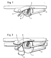
- Figure 1 represents a side view of a fuel tank 1 holding a fuel for the operation of a vehicle propulsion system, such as a hydrogen-powered internal combustion engine or a fuel cell system.
- the fuel tank 1 can be arranged in an underbody area of the vehicle, preferably behind the rear axle 4 in relation to the driver, thereby saving space, and extends between the two rear wheels.
- the wheel suspension 2 is indicated schematically.
- the fuel tank 1 can consist of a single tank or of more individual tanks.
- the fuel tank 1 is mounted on a structure 3, preferably a movable frame 3, which can move the fuel tank out of the crash zone in case of an impact and which can also serve as a protective frame for the fuel tank 1. With help of this protecting frame 3, the fuel tank 1 can be slid under the rear axle in case of a rear crash.
- the movable frame 3 holds the said one fuel tank 1.
- the said frame 3 consists of two side parts each of which is mounted with two arms 8, 9 to the underbody of the vehicle.
- the fuel tank 1 extends between the two side parts more or less parallel to the rear or front axle. Each side part of the frame 3 is mounted with two arms 8, 9 to the underbody of the vehicle.
- the side view of the frame 3 is a box-like shape.
- the arm 8 which is adjacent to the axle 4, has a rectangular part 6, in which the fuel tank 1 is mounted.
- This arm 8 is mounted fixed to the underbody structure, which means that it can rotate or can be tilted around its attachment.
- the other arm 9, which is afar from the axle 4, is slidably mounted to the underbody structure of the vehicle. In case of an impact this arm 9 moves towards the axle 4 causing the arm 8 to rotate subsequently moving the tank 1 down and towards the axle 4.
- FIG. 2 illustrates the sliding of the fuel tank 1 in case of a crash.
- Fig. 2a exhibits the situation before crash, with the tank 1 mounted behind the rear axle 4.
- the movable frame 3 starts to slide and deform towards the rear axle 4 (Fig. 2b) and continues to slide and move the tank 1 away, out of the crash area (Fig. 2c).
- the situation after crash is illustrated in Fig. 2d.
- the fuel tank 1 comes to rest securely unde the rear axle 4 and is safely hold in the frame 3.
- the available deformation distance from the tail end of the vehicle to the tank 1 is increased.
- FIG 3 another feature of the invention is illustrated.
- the tank 1 can be prevented from colliding with the road surface at a high force load by making use of a protective airbag system 5 under the tank 1.
- the aurbag system 5 consists of one or more individual airbags arranged around the tank 1.
- the tank 1 when let free to slide down during crash will be subjected to high loads of several g due to the self-weight of the tank 1 and the frame 3.
- the moving frame 3 can be integrated with airbag systems 5, which can be triggered almost instantaneously at the time of the sliding.
- the tank 1 With help of the protective frame 3 the tank 1 can be slid at least partially under the rear axle 4 and the airbag system 5 are inflated due to a signal from a conventional crash sensor of a conventional vehicle control unit or the like.
- the airbag system 5 help the tank 1 in reaching a safe position close to the road surface, but letting the tank 1 descend under the axle 4 in a safe and controlled manner.
- the airbag system 5 when triggered inflate under tremendeous pressure. This pressure, which is controllable, can possibly clear the road surface around it and make free of small distrubances and obstacles which could damage the tank 1. When the airbag system 5 is inflated, the tank 1 can be made to fall over it, which will ensure the safe descent of the tank 1 to a lower and safer level away from the collision level.
- the placement of the airbag system 5 can be decided on the kinetmatics analysis of the frame structure of the vehicle, in order to get an optimum usage of the airbag system 5. This safety feature can be easily incorporated, by integrating it with already existing safety sensors and instrumentation. This proves to be very economical since this safety feature does not require any additional sensor and measurement system onboard.
- Figure 4 represents the situation with nitrogen gas in the vicinity of the tank 1 after the crash.
- the airbag system 5 uses an inert gas as inflating gas.
- the electric power supply of the vehicle is automatically shut off and also the valves of the hydrogen tank 1 in case of impact.
- Solid propellant gas generators have been used for a long time as fire suppressants in many fire-fighting allications.
- One such gas propellants is sodium azide.
- Sodium azide is used to inflate the airbags in automobiles. This compound, when ignited at 270°C, will decompose rapidly releasing large amounts of nitrogen.
- this nitrogen gas being lighter than oxygen, will displace oxygen molecules from the vicinity of the tank 1 and make the atmosphere inert for a short period of time. This reduces the chances of a combustible mixture formation by hydrogen and oxygen molecules, thereby minimizing the risk of undesired combustion of the hydrogen gas.
- the nitrogen gas can form a barrier between the oxygen containing ambient air and hydrogen which might possibly bleed out of the tank 1 or ruptured tubes or vents (not shown)
Landscapes
- Engineering & Computer Science (AREA)
- Mechanical Engineering (AREA)
- Life Sciences & Earth Sciences (AREA)
- Sustainable Development (AREA)
- Sustainable Energy (AREA)
- Chemical & Material Sciences (AREA)
- Combustion & Propulsion (AREA)
- Transportation (AREA)
- Cooling, Air Intake And Gas Exhaust, And Fuel Tank Arrangements In Propulsion Units (AREA)
Abstract
Description
- The invention relates to a vehicle having at least a fuel tank for holding a fuel for the operation of a vehicle propulsion system according to the preamble of
Claim 1. - US patent 4,570,446 A1 discloses a vehicle having a tank for fuel in the form of hydrogen. In this arrangement, a plurality of cylinders is arranged in a housing and filled with a hydrogen- storing medium. In these cylinders hydrogen can be desorbed under the essfet of high temperatures and fed to an internal combustion engine. The adsorption and desorption of hydrogen occurs at low pressures. It is possible, however, to carry gaseous hydrogen under high pressures in this vehicle tank.
- An object of the invnetion is to specify a vehicle having a fuel tank, which is suitable for the transport and storage of gaseous or liquid hydrogen.
- This object is achieved in a vehicle having at least one fuel tank for holding a fuel for the operation of a vehicle propulsion system, wherein a structure is provided for executing a controlled deflection movement of said one fuel tank, so that in event if an impact a movement can be executed shifting said one fuel tank towards an essentially crash proof zone area of the vehicle and simultaneously releasing an inert gas from an air bag filling the volume around the fuel tank.
- The advantage of the solution according to the invnetion resides in the fact that a very compact apparatus is created and secondly that in the event of a crash the fuel tank is protected from the effect of excessive crash energy as well as from an oxygen containing atmosphere and undesirable ingnition sparks.
- It goes without saying that the aforementioned features and those still to be explained below can be used not only in the particular combination specified, but also in other combinations or individually, without departing from the scope of the present invention.
- Other objects, advantages and novel features of the present invention will become apparent from the following detailed description of the invention when considered with the accompanying drawings, where the figures show
- Figure 1
- an illustration of the fuel tank mounted on a preferred movable frame,
- Figure 2
- an illustration of 4 intermediate stages of the
sliding of the fuel tank with 2a before crash, 2b
intermediate stage 1, 2cintermediate stage 2 and 2c after crash, - Figure 3
- an illustration the tank protected by an air bag and
- Figure 4
- an illustration of the inerting of the atmosphere surrounding the fuel tank.
- The invention is particularly suited to vehicles having a pressurized gas tank, especially to vehicles that are operated on hydrogen.
- Figure 1 represents a side view of a
fuel tank 1 holding a fuel for the operation of a vehicle propulsion system, such as a hydrogen-powered internal combustion engine or a fuel cell system. Thefuel tank 1 can be arranged in an underbody area of the vehicle, preferably behind therear axle 4 in relation to the driver, thereby saving space, and extends between the two rear wheels. Thewheel suspension 2 is indicated schematically. Thefuel tank 1 can consist of a single tank or of more individual tanks. - The
fuel tank 1 is mounted on astructure 3, preferably amovable frame 3, which can move the fuel tank out of the crash zone in case of an impact and which can also serve as a protective frame for thefuel tank 1. With help of this protectingframe 3, thefuel tank 1 can be slid under the rear axle in case of a rear crash. Themovable frame 3 holds the said onefuel tank 1. The saidframe 3 consists of two side parts each of which is mounted with twoarms fuel tank 1 extends between the two side parts more or less parallel to the rear or front axle. Each side part of theframe 3 is mounted with twoarms - The side view of the
frame 3 is a box-like shape. Thearm 8 which is adjacent to theaxle 4, has arectangular part 6, in which thefuel tank 1 is mounted. Thisarm 8 is mounted fixed to the underbody structure, which means that it can rotate or can be tilted around its attachment. Theother arm 9, which is afar from theaxle 4, is slidably mounted to the underbody structure of the vehicle. In case of an impact thisarm 9 moves towards theaxle 4 causing thearm 8 to rotate subsequently moving thetank 1 down and towards theaxle 4. - Figure 2 illustrates the sliding of the
fuel tank 1 in case of a crash. Fig. 2a exhibits the situation before crash, with thetank 1 mounted behind therear axle 4. When a crash occurs, themovable frame 3 starts to slide and deform towards the rear axle 4 (Fig. 2b) and continues to slide and move thetank 1 away, out of the crash area (Fig. 2c). The situation after crash is illustrated in Fig. 2d. Thefuel tank 1 comes to rest securely unde therear axle 4 and is safely hold in theframe 3. When thetank 1 is slid under theaxle 4 the available deformation distance from the tail end of the vehicle to thetank 1 is increased. - In Figure 3 another feature of the invention is illustrated. The
tank 1 can be prevented from colliding with the road surface at a high force load by making use of aprotective airbag system 5 under thetank 1. Theaurbag system 5 consists of one or more individual airbags arranged around thetank 1. - The
tank 1 when let free to slide down during crash will be subjected to high loads of several g due to the self-weight of thetank 1 and theframe 3. In order to prevent thetank 1 from being damaged due to this force load, the movingframe 3 can be integrated withairbag systems 5, which can be triggered almost instantaneously at the time of the sliding. - With help of the
protective frame 3 thetank 1 can be slid at least partially under therear axle 4 and theairbag system 5 are inflated due to a signal from a conventional crash sensor of a conventional vehicle control unit or the like. Theairbag system 5 help thetank 1 in reaching a safe position close to the road surface, but letting thetank 1 descend under theaxle 4 in a safe and controlled manner. - The
airbag system 5, when triggered inflate under tremendeous pressure. This pressure, which is controllable, can possibly clear the road surface around it and make free of small distrubances and obstacles which could damage thetank 1. When theairbag system 5 is inflated, thetank 1 can be made to fall over it, which will ensure the safe descent of thetank 1 to a lower and safer level away from the collision level. The placement of theairbag system 5 can be decided on the kinetmatics analysis of the frame structure of the vehicle, in order to get an optimum usage of theairbag system 5. This safety feature can be easily incorporated, by integrating it with already existing safety sensors and instrumentation. This proves to be very economical since this safety feature does not require any additional sensor and measurement system onboard. - Figure 4 represents the situation with nitrogen gas in the vicinity of the
tank 1 after the crash. An advantage is that theairbag system 5 uses an inert gas as inflating gas. Preferably, the electric power supply of the vehicle is automatically shut off and also the valves of thehydrogen tank 1 in case of impact. - Solid propellant gas generators have been used for a long time as fire suppressants in many fire-fighting allications. One such gas propellants is sodium azide. Sodium azide is used to inflate the airbags in automobiles. This compound, when ignited at 270°C, will decompose rapidly releasing large amounts of nitrogen. When the nitrogen gas is released out from the
airbag system 5, this nitrogen gas, being lighter than oxygen, will displace oxygen molecules from the vicinity of thetank 1 and make the atmosphere inert for a short period of time. This reduces the chances of a combustible mixture formation by hydrogen and oxygen molecules, thereby minimizing the risk of undesired combustion of the hydrogen gas. The nitrogen gas can form a barrier between the oxygen containing ambient air and hydrogen which might possibly bleed out of thetank 1 or ruptured tubes or vents (not shown) - Should a
fuel tank 1 be alternatively or additionally arranged in front of the front axle of the vehicle, these considerations apply analogously in the event of a frontal impact. Thefuel tank 1 would then be shifted towards the front axle, preferably under the front axle, in the event of an impact. - The foregoing dislclosure has been set forth merely to illustrate the invention and is not intended to be limiting. Since modifications of the dislcosed embodiments incorporating the spirit and substance of the invention may occur to persons skilled in the art, the invention should be construed to include everything within the scope of the appended claims and equivalents thereof.
Claims (8)
- Vehicle having at least one fuel tank (1) for holding a fuel for the operation of a vehicle propulsion system,
characterized in that
a structure (3) is provided for executing a controlled deflection movement of said one fuel tank (1) so that in the event of an impact, a movement can be executed shifting said one fuel tank (1) away from the area of impact and an airbag system (5) is provided for simultaneously inflating under or around the said one tank (1) preventing it from colliding with the surface road or obstacles. - Vehicle according to Claim 1,
characterized in that
the said one fuel tank (1) is arranged in an underbody area of the vehicle. - Vehicle according to Claim 1,
characterized in that
the said one fuel tank (1) is arranged in an area in front of a front axle or behind a rear axle (4). - Vehicle according to Claim 3,
characterized in that
the controlled deflection movement of said one fuel tank (1) is shifting said one fuel tank (1) towards the respective adjacent front axle or rear axle (4). - Vehicle according to Claim 1,
characterized in that
the said frame (3) consists of two side parts each of which is mounted with two arms (8, 9) to the underbody of the vehicle where the fuel tank (1) extends between the two parts. - Vehicle according to Claim 5,
characterized in that
the one arm (8) of the said movable frame (3) close to the axle (4) is mounted fixed but tiltable or rotatable and the other arm (9) is slidably mounted to the underbody structure of the vehicle. - Vehicle according to Claim 1,
characterized in that
when the airbag system (5) is inflated the said one fuel tank (1) falls over the airbag system (5) or at least one airbag of said airbag system (5). - Vehicle according to Claim 1,
characterized in that
the said one fuel tank (1) holds compressed hydrogen as a fuel.
Priority Applications (2)
| Application Number | Priority Date | Filing Date | Title |
|---|---|---|---|
| DE2002625679 DE60225679T2 (en) | 2002-07-11 | 2002-07-11 | Vehicle with fuel tank |
| EP20020015408 EP1380460B1 (en) | 2002-07-11 | 2002-07-11 | Vehicle with fuel tank |
Applications Claiming Priority (1)
| Application Number | Priority Date | Filing Date | Title |
|---|---|---|---|
| EP20020015408 EP1380460B1 (en) | 2002-07-11 | 2002-07-11 | Vehicle with fuel tank |
Publications (2)
| Publication Number | Publication Date |
|---|---|
| EP1380460A1 true EP1380460A1 (en) | 2004-01-14 |
| EP1380460B1 EP1380460B1 (en) | 2008-03-19 |
Family
ID=29724430
Family Applications (1)
| Application Number | Title | Priority Date | Filing Date |
|---|---|---|---|
| EP20020015408 Expired - Lifetime EP1380460B1 (en) | 2002-07-11 | 2002-07-11 | Vehicle with fuel tank |
Country Status (2)
| Country | Link |
|---|---|
| EP (1) | EP1380460B1 (en) |
| DE (1) | DE60225679T2 (en) |
Cited By (3)
| Publication number | Priority date | Publication date | Assignee | Title |
|---|---|---|---|---|
| EP4063164A1 (en) * | 2021-03-22 | 2022-09-28 | MARMIX GmbH & Co. KG | Axle, commercial vehicle with axle and use |
| DE102007034299B4 (en) | 2006-07-27 | 2023-07-20 | GM Global Technology Operations LLC (n. d. Ges. d. Staates Delaware) | Tank assembly for use in a vehicle |
| EP4438817A1 (en) * | 2023-03-30 | 2024-10-02 | Liebherr-Werk Bischofshofen GmbH | A working machine |
Families Citing this family (1)
| Publication number | Priority date | Publication date | Assignee | Title |
|---|---|---|---|---|
| US9561765B1 (en) | 2015-08-04 | 2017-02-07 | Ford Global Technologies, Llc | Fuel tank assembly including inflatable member |
Citations (4)
| Publication number | Priority date | Publication date | Assignee | Title |
|---|---|---|---|---|
| US4570446A (en) | 1984-05-22 | 1986-02-18 | Mitsui & Co., Ltd. | Fuel tank for hydrogen vehicle and fuel supplying system |
| DE4009244A1 (en) * | 1990-03-22 | 1991-09-26 | Diehl Gmbh & Co | Safety protection for container on goods vehicle - uses side-mounted air bags operated by tilt sensors |
| JPH061298A (en) * | 1992-06-24 | 1994-01-11 | Mitsubishi Heavy Ind Ltd | Fuel tank |
| DE19806607A1 (en) * | 1997-02-20 | 1998-08-27 | Volkswagen Ag | Deformation-protection device for fuel tank in vehicle |
-
2002
- 2002-07-11 EP EP20020015408 patent/EP1380460B1/en not_active Expired - Lifetime
- 2002-07-11 DE DE2002625679 patent/DE60225679T2/en not_active Expired - Lifetime
Patent Citations (4)
| Publication number | Priority date | Publication date | Assignee | Title |
|---|---|---|---|---|
| US4570446A (en) | 1984-05-22 | 1986-02-18 | Mitsui & Co., Ltd. | Fuel tank for hydrogen vehicle and fuel supplying system |
| DE4009244A1 (en) * | 1990-03-22 | 1991-09-26 | Diehl Gmbh & Co | Safety protection for container on goods vehicle - uses side-mounted air bags operated by tilt sensors |
| JPH061298A (en) * | 1992-06-24 | 1994-01-11 | Mitsubishi Heavy Ind Ltd | Fuel tank |
| DE19806607A1 (en) * | 1997-02-20 | 1998-08-27 | Volkswagen Ag | Deformation-protection device for fuel tank in vehicle |
Non-Patent Citations (1)
| Title |
|---|
| PATENT ABSTRACTS OF JAPAN vol. 018, no. 192 (M - 1587) 4 April 1994 (1994-04-04) * |
Cited By (3)
| Publication number | Priority date | Publication date | Assignee | Title |
|---|---|---|---|---|
| DE102007034299B4 (en) | 2006-07-27 | 2023-07-20 | GM Global Technology Operations LLC (n. d. Ges. d. Staates Delaware) | Tank assembly for use in a vehicle |
| EP4063164A1 (en) * | 2021-03-22 | 2022-09-28 | MARMIX GmbH & Co. KG | Axle, commercial vehicle with axle and use |
| EP4438817A1 (en) * | 2023-03-30 | 2024-10-02 | Liebherr-Werk Bischofshofen GmbH | A working machine |
Also Published As
| Publication number | Publication date |
|---|---|
| DE60225679D1 (en) | 2008-04-30 |
| EP1380460B1 (en) | 2008-03-19 |
| DE60225679T2 (en) | 2009-04-30 |
Similar Documents
| Publication | Publication Date | Title |
|---|---|---|
| KR100582971B1 (en) | Expandable Cushion Mechanism | |
| CN1095765C (en) | Method of filling empty, flexible container, and a container device | |
| US3606377A (en) | Vehicle crash restraint system | |
| EP0686530B1 (en) | Large L/D ratio tubular hybrid gas generator for the inflation of air bags | |
| US6692028B2 (en) | Vehicle with fuel tank | |
| US6505890B2 (en) | Aircraft seat structure | |
| IL120498A (en) | External airbag protection system for helicopter | |
| JP3044475U (en) | Directional compressed gas inflator | |
| US3618974A (en) | Vehicle safety apparatus | |
| EP1380460B1 (en) | Vehicle with fuel tank | |
| US20040124619A1 (en) | Adaptive output airbag inflation device | |
| US7520531B2 (en) | Inflator device pressure relief | |
| US6981718B2 (en) | Projectile firing barrel | |
| CN104118383A (en) | Supplemental restraint system | |
| CN113002408A (en) | Tank assembly for conveying dangerous liquid and logistics vehicle thereof | |
| WO2022146311A1 (en) | Vehicle under-hood and trunk safety cushion | |
| US20240424891A1 (en) | Energy absorbing system for vehicle fuel gas storage systems and related aspects | |
| EP0697970A1 (en) | Means for filling an airbag | |
| EP1363803B1 (en) | Aircraft seat structure | |
| WO1996010496A1 (en) | Means and method for filling an airbag | |
| WO2011024203A2 (en) | Airbag inflator system | |
| CN112937413A (en) | Logistics vehicle for conveying dangerous liquid | |
| JPH0585149A (en) | Vehicle accessory mounting structure | |
| KR19980022521U (en) | Car airbag system | |
| HU213887B (en) | Structure for immediate filling gas containers with flexible walls |
Legal Events
| Date | Code | Title | Description |
|---|---|---|---|
| PUAI | Public reference made under article 153(3) epc to a published international application that has entered the european phase |
Free format text: ORIGINAL CODE: 0009012 |
|
| 17P | Request for examination filed |
Effective date: 20030215 |
|
| AK | Designated contracting states |
Kind code of ref document: A1 Designated state(s): AT BE BG CH CY CZ DE DK EE ES FI FR GB GR IE IT LI LU MC NL PT SE SK TR |
|
| AX | Request for extension of the european patent |
Extension state: AL LT LV MK RO SI |
|
| AKX | Designation fees paid |
Designated state(s): DE FR GB IT |
|
| RAP1 | Party data changed (applicant data changed or rights of an application transferred) |
Owner name: DAIMLERCHRYSLER AG |
|
| GRAP | Despatch of communication of intention to grant a patent |
Free format text: ORIGINAL CODE: EPIDOSNIGR1 |
|
| RAP1 | Party data changed (applicant data changed or rights of an application transferred) |
Owner name: DAIMLER AG |
|
| GRAS | Grant fee paid |
Free format text: ORIGINAL CODE: EPIDOSNIGR3 |
|
| GRAL | Information related to payment of fee for publishing/printing deleted |
Free format text: ORIGINAL CODE: EPIDOSDIGR3 |
|
| GRAS | Grant fee paid |
Free format text: ORIGINAL CODE: EPIDOSNIGR3 |
|
| GRAA | (expected) grant |
Free format text: ORIGINAL CODE: 0009210 |
|
| AK | Designated contracting states |
Kind code of ref document: B1 Designated state(s): DE FR GB IT |
|
| REG | Reference to a national code |
Ref country code: GB Ref legal event code: FG4D |
|
| REF | Corresponds to: |
Ref document number: 60225679 Country of ref document: DE Date of ref document: 20080430 Kind code of ref document: P |
|
| PGFP | Annual fee paid to national office [announced via postgrant information from national office to epo] |
Ref country code: FR Payment date: 20080715 Year of fee payment: 7 |
|
| EN | Fr: translation not filed | ||
| PLBE | No opposition filed within time limit |
Free format text: ORIGINAL CODE: 0009261 |
|
| STAA | Information on the status of an ep patent application or granted ep patent |
Free format text: STATUS: NO OPPOSITION FILED WITHIN TIME LIMIT |
|
| 26N | No opposition filed |
Effective date: 20081222 |
|
| PG25 | Lapsed in a contracting state [announced via postgrant information from national office to epo] |
Ref country code: FR Free format text: LAPSE BECAUSE OF FAILURE TO SUBMIT A TRANSLATION OF THE DESCRIPTION OR TO PAY THE FEE WITHIN THE PRESCRIBED TIME-LIMIT Effective date: 20090109 |
|
| PGFP | Annual fee paid to national office [announced via postgrant information from national office to epo] |
Ref country code: GB Payment date: 20120731 Year of fee payment: 11 |
|
| PGFP | Annual fee paid to national office [announced via postgrant information from national office to epo] |
Ref country code: IT Payment date: 20120725 Year of fee payment: 11 |
|
| GBPC | Gb: european patent ceased through non-payment of renewal fee |
Effective date: 20130711 |
|
| PG25 | Lapsed in a contracting state [announced via postgrant information from national office to epo] |
Ref country code: GB Free format text: LAPSE BECAUSE OF NON-PAYMENT OF DUE FEES Effective date: 20130711 |
|
| PG25 | Lapsed in a contracting state [announced via postgrant information from national office to epo] |
Ref country code: IT Free format text: LAPSE BECAUSE OF NON-PAYMENT OF DUE FEES Effective date: 20130711 |
|
| PGFP | Annual fee paid to national office [announced via postgrant information from national office to epo] |
Ref country code: DE Payment date: 20140930 Year of fee payment: 13 |
|
| REG | Reference to a national code |
Ref country code: DE Ref legal event code: R119 Ref document number: 60225679 Country of ref document: DE |
|
| PG25 | Lapsed in a contracting state [announced via postgrant information from national office to epo] |
Ref country code: DE Free format text: LAPSE BECAUSE OF NON-PAYMENT OF DUE FEES Effective date: 20160202 |