EP1380320A1 - Fall protection follower device along a fixed rope - Google Patents
Fall protection follower device along a fixed rope Download PDFInfo
- Publication number
- EP1380320A1 EP1380320A1 EP03354059A EP03354059A EP1380320A1 EP 1380320 A1 EP1380320 A1 EP 1380320A1 EP 03354059 A EP03354059 A EP 03354059A EP 03354059 A EP03354059 A EP 03354059A EP 1380320 A1 EP1380320 A1 EP 1380320A1
- Authority
- EP
- European Patent Office
- Prior art keywords
- roller
- rope
- fall arrest
- support arm
- arrest device
- Prior art date
- Legal status (The legal status is an assumption and is not a legal conclusion. Google has not performed a legal analysis and makes no representation as to the accuracy of the status listed.)
- Granted
Links
Images


Classifications
-
- A—HUMAN NECESSITIES
- A62—LIFE-SAVING; FIRE-FIGHTING
- A62B—DEVICES, APPARATUS OR METHODS FOR LIFE-SAVING
- A62B1/00—Devices for lowering persons from buildings or the like
- A62B1/06—Devices for lowering persons from buildings or the like by making use of rope-lowering devices
- A62B1/14—Devices for lowering persons from buildings or the like by making use of rope-lowering devices with brakes sliding on the rope
-
- A—HUMAN NECESSITIES
- A62—LIFE-SAVING; FIRE-FIGHTING
- A62B—DEVICES, APPARATUS OR METHODS FOR LIFE-SAVING
- A62B35/00—Safety belts or body harnesses; Similar equipment for limiting displacement of the human body, especially in case of sudden changes of motion
- A62B35/04—Safety belts or body harnesses; Similar equipment for limiting displacement of the human body, especially in case of sudden changes of motion incorporating energy absorbing means
Definitions
- fall arrest devices follow the progression of the person along the rope without generating blocking.
- the person is free to move without any intervention manual release of the fall arrest device.
- the blocking occurs only in case of fall.
- the restraint system of known fall arrest devices generally includes a pivoting lever having at one end an attachment ring for the connection to a shoulder belt, and at the opposite end a locking cam of the rope.
- a pivoting lever having at one end an attachment ring for the connection to a shoulder belt, and at the opposite end a locking cam of the rope.
- Such The arrangement behaves like a cleat which may prevent blocking if the user were to grip the lever in the event of a fall.
- WO 00/24471 relates to a locking device bidirectional for a fall arrest apparatus, comprising a locking member equipped with two cams actuated independently by an organ of common blockage in response to a sudden change in weight.
- the blocking of each of the cams depends on the inclination of the rope relative to the chassis of the device.
- US 4923037 discloses a fall arrest device having a system of restraint consisting of an articulated support arm, which is equipped with a wheel cylindrical mounted free rotation, and a centrifugal mechanical coupling arranged in a ratchet.
- the periphery of the wheel has a series of teeth constituting a pinion causing rotation of the wheel by friction with the cable.
- the radial direction of the teeth does not allow to obtain a functioning optimum fall arrest system.
- to insert the vertical lifeline in the fall arrest device it is necessary to make use of a U-shaped articulated, and to rotate outward, which complicates maneuvers.
- the object of the invention is to provide a fall arrest apparatus for a fixed rope, to obtain maximum safety for the user in the event of a fall, regardless of the inclination of the rope or a handling error of the device.
- the fall arrest device is characterized in that the surface roller device is provided with a plurality of pins arranged for generate a rotation of the roller in the direction of the descent, and a slip on the rope in the direction of the climb, and that the body has a chute rectilinear U-shaped for the passage of the rope, said chute having holes for the passage of fastening means.
- the mechanical coupling is disposed inside the roller, and comprises at least one movable weight by centrifugal effect along a ramp as a function of speed or acceleration of the drive member of the roller.
- the weight is associated with a spring of return biasing the mechanical coupling in the disengaged position, the threshold when the centrifugal force is greater than the force return spring.
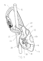
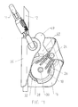
- a fall arrest device 10 is used for the safety of a person moving along a fixed 12 insurance rope.
- a carabiner 14 is hooked to the fall arrest device 10 so as to be connected to the harness, either live, either through an absorption lanyard.
- the fall arrest device 10 follows the progression of the person along the rope 12 without generating blocking. The person is free to move without any intervention Manual release of the fall arrest device 10.
- the fall arrest device 10 is composed of a rigid body 16 and a control system.
- mobile retainer 18 cooperating with the rope 12 to occupy either a position blocking function in the event of a fall, ie an inactive unlocking position in the direction of the climb, or in the opposite direction during a controlled descent.
- the body 16 which is preferably metallic, comprises a straight trough 20 made of U shape for the passage of the rope 12, and a stirrup 22 for mounting a first axis 24 extending transversely to the direction of the chute 20.
- the upper part of the chute 20 is pierced by two holes 23 to allow the passage of the carabiner 14 attachment to the harness.
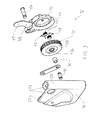
- the retaining member 18 comprises a support arm 26 articulated on the first axis 24, and a wheel-shaped roller 28 mounted for free rotation on a second axis 30 integral with the support arm 26.
- the peripheral surface of the roller 28 is cylindrical, and is provided with a plurality of pins 32 each having an inclination predetermined with respect to the radial direction passing through the axis 30.
- a spring torsion (not shown) is threaded on the first axis 24 and urges the arm support 26 in the direction of the chute 20.
- the roller 28 is provided with an internal drive member 33, pierced by an orifice 34 central cylindrical, which is traversed by a tubular bearing 36 introduced on the second fixed axis 30. Inside the roller 28 is in addition a mechanical coupling 38 formed by a pair of weights 40 cylindrical arranged between opposite ramps 42 of the organ 33 and a circular flange 44 of the support arm 26.
- Each weight 40 is associated with a spring 46 in the shape of a pin intended for urging the mechanical coupling 38 to the disengaged position when the normal use of the fall arrest device 10.
- the 40 flyweights are in a hollow of the drive member 33, in order to interrupt the mechanical coupling 38 between the roller 28 and the arm 26.
- the roller 28 is then rotated by the friction of the rope 12, while the support arm 26 is in the inactive position allowing the device fall arrest 10 to follow the progress of the user on the ascent or descent.
- the restoring force of the springs 46 defines the coupling threshold as a function of the speed or acceleration of the drive member 33 of the rotary roller 28.
- the abrupt rotation of the roller 28 on the axis 30 causes the displacement of the weights 40 by centrifugal effect to the engaged position. This movement is effected against the restoring force of the springs 46, and causes jamming of the weights 40 between the flange 44 and the body 33.
- the mechanical coupling in the engaged position thus makes the roller 28 secured to the support arm 26, so as to form a cleat wedge capable of pivoting about the first axis 24, and blocking the fall by blocking the rope 12.
- the pivoting support arm 26 is equipped with a stop 48 intended to cooperate with the carabiner 14 to limit the pivoting stroke of the arm 26 in the inactive unlock position. The response time of the support arm 26 pivoting is thus reduced to the minimum to obtain the blocking in case of fall.
- the end of the stop 48 is provided with a protuberance 49 intended for intercalate between the two holes 23 of the body 16 to prevent the establishment carabiner 14 before the introduction of the rope 12.
- the abrupt rotation of the roller and the drive member 33 in the clockwise subjects the weights 40 to a centrifugal force, which is higher and opposite to the restoring force of the springs 46.
- the weights 40 move on the ramps 42, which causes jamming weights 40 between the flange 44 and the drive member 33.
- the mechanical coupling is then in the engaged position, making the roller 28 secured to the support arm 26.
- the assembly constitutes a jamming cleat rotatable clockwise about the first axis 24, and blocking the fall by blocking the rope 12. Unblocking the weights 40 intervenes by a manual action of the operator to maintain the roller 28 against the rope 12, and by raising the body 16 by a few centimeters.
- the stop 48 is replaced by a security flap 50, which is arranged to fill the same functions of the abutment 48 of the preceding Figures 1-12, in addition to a positioning function of the rope 12 at the bottom of the chute 20 before the introduction of the carabiner 14 in the holes 23.
- the safety flap 50 is pivotally mounted on an axis 52, and comprises a oblong aperture 54 inside which moves a lever of control 56 secured to the support arm 26.
- the opening 54 has a double angled ramp for moving the flap 50 according to the pivoting movement of the arm 26.
- the flap 50 further comprises a wing 58 intended to press the rope 12 at the bottom of the chute 20.
Abstract
Description
L'invention est relative à un dispositif antichute suiveur utilisé avec une corde fixe de sécurité, et comprenant :
- un corps équipé d'un système de retenue agencé pour occuper soit une position active de blocage en cas de chute, soit une position inactive de déblocage autorisant la progression de l'utilisateur le long de la corde dans le sens de la montée, ou dans le sens opposé lors d'une descente contrôlée, ledit système de retenue comportant un bras support articulé sur un premier axe du corps, un galet en forme de roue cylindrique montée à rotation libre sur un deuxième axe solidaire du bras support, et un accouplement mécanique centrifuge agencé entre un organe d'entraínement du galet et le bras support de manière à occuper une position débrayée ou une position embrayée,
- et des moyens d'attache pour la liaison du corps à un baudrier d'assurance de l'utilisateur.
- a body equipped with a retaining system arranged to occupy either an active blocking position in the event of a fall, or an inactive unlocking position allowing the progression of the user along the rope in the direction of the climb, or in the opposite direction during a controlled descent, said retaining system comprising a support arm articulated on a first axis of the body, a cylindrical wheel-shaped roller mounted for free rotation on a second axis integral with the support arm, and a mechanical coupling centrifugal arranged between a drive member of the roller and the support arm so as to occupy a disengaged position or an engaged position,
- and attachment means for binding the body to a user's insurance belt.
Lors de l'utilisation normale de montée ou de descente, les dispositifs antichute suivent la progression de la personne le long de la corde sans engendrer de blocage. La personne est libre de se déplacer sans aucune intervention manuelle de déblocage du dispositif antichute. Le blocage intervient uniquement en cas de chute.During normal use of ascent or descent, fall arrest devices follow the progression of the person along the rope without generating blocking. The person is free to move without any intervention manual release of the fall arrest device. The blocking occurs only in case of fall.
Le système de retenue des dispositifs antichute connus comporte généralement un levier pivotant ayant à l'une des extrémités un anneau d'attache pour la liaison à un baudrier, et à l'extrémité opposée une came de blocage de la corde. Un tel agencement se comporte comme un taquet coinceur, lequel risque d'empêcher le blocage si l'utilisateur venait à s'agripper au levier en cas de chute.The restraint system of known fall arrest devices generally includes a pivoting lever having at one end an attachment ring for the connection to a shoulder belt, and at the opposite end a locking cam of the rope. Such The arrangement behaves like a cleat which may prevent blocking if the user were to grip the lever in the event of a fall.
Le document WO 00/24471 se rapporte à un dispositif de verrouillage bidirectionnel pour un appareil antichute, comprenant un organe de verrouillage équipé de deux cames actionnées de manière indépendante par un organe de blocage commun en réaction à un brusque changement de poids. Le blocage de chacune des cames dépend de l'inclinaison de la corde par rapport au châssis de l'appareil.WO 00/24471 relates to a locking device bidirectional for a fall arrest apparatus, comprising a locking member equipped with two cams actuated independently by an organ of common blockage in response to a sudden change in weight. The blocking of each of the cams depends on the inclination of the rope relative to the chassis of the device.
Le document US 4923037 décrit un dispositif antichute ayant un système de retenue composé d'un bras support articulé, lequel est équipé d'une roue cylindrique montée à rotation libre, et d'un accouplement mécanique centrifuge agencé en cliquet. La périphérie de la roue comporte une série de dents constituant un pignon provoquant la rotation de la roue par effet de friction avec le câble. La direction radiale des dents ne permet pas d'obtenir un fonctionnement optimum du dispositif antichute. De plus, pour insérer la ligne de vie verticale dans le dispositif antichute, il est nécessaire de faire usage d'une cornière en U articulée, et de la faire pivoter vers l'extérieur, ce qui complique les manoeuvres.US 4923037 discloses a fall arrest device having a system of restraint consisting of an articulated support arm, which is equipped with a wheel cylindrical mounted free rotation, and a centrifugal mechanical coupling arranged in a ratchet. The periphery of the wheel has a series of teeth constituting a pinion causing rotation of the wheel by friction with the cable. The radial direction of the teeth does not allow to obtain a functioning optimum fall arrest system. In addition, to insert the vertical lifeline in the fall arrest device, it is necessary to make use of a U-shaped articulated, and to rotate outward, which complicates maneuvers.
L'objet de l'invention consiste à réaliser un appareil antichute pour corde fixe, permettant d'obtenir une sécurité maximale de l'utilisateur en cas de chute, indépendamment de l'inclinaison de la corde ou d'une erreur de manipulation de l'appareil. The object of the invention is to provide a fall arrest apparatus for a fixed rope, to obtain maximum safety for the user in the event of a fall, regardless of the inclination of the rope or a handling error of the device.
Le dispositif antichute selon l'invention est caractérisé en ce que la surface périphérique du galet est munie d'une pluralité de picots agencés pour engendrer une rotation du galet dans le sens de la descente, et un glissement sur la corde dans le sens de la montée, et que le corps comporte une goulotte rectiligne en forme de U pour le passage de la corde, ladite goulotte ayant des trous pour le passage des moyens d'attache.The fall arrest device according to the invention is characterized in that the surface roller device is provided with a plurality of pins arranged for generate a rotation of the roller in the direction of the descent, and a slip on the rope in the direction of the climb, and that the body has a chute rectilinear U-shaped for the passage of the rope, said chute having holes for the passage of fastening means.
Lors de l'utilisation normale de montée ou de descente, l'accouplement se trouve en position débrayée, et le dispositif antichute suit la progression de la personne le long de la corde sans aucune intervention manuelle de déblocage du système de retenue. Le blocage intervient automatiquement en cas de chute, même si l'utilisateur s'agrippe à l'appareil. Dans ce cas, l'accouplement se trouve en position embrayée entraínant une forte pression du galet contre la corde.During normal use of ascent or descent, mating is in the disengaged position, and the fall arrest device follows the progression of the person along the rope without any manual intervention to unblock the system restraint. Blocking occurs automatically in case of a fall, even if the user clings to the device. In this case, the coupling is in engaged position causing a strong pressure of the roller against the rope.
Selon un mode de réalisation préférentiel, l'accouplement mécanique est disposé à l'intérieur du galet, et comprend au moins une masselotte mobile par effet centrifuge le long d'une rampe en fonction de la vitesse ou de l'accélération de l'organe d'entraínement du galet. La masselotte est associée à un ressort de rappel sollicitant l'accouplement mécanique en position débrayée, le seuil d'accouplement étant atteint lorsque la force centrifuge est supérieure à la force de rappel du ressort.According to a preferred embodiment, the mechanical coupling is disposed inside the roller, and comprises at least one movable weight by centrifugal effect along a ramp as a function of speed or acceleration of the drive member of the roller. The weight is associated with a spring of return biasing the mechanical coupling in the disengaged position, the threshold when the centrifugal force is greater than the force return spring.
Il est bien entendu possible d'utiliser tout autre type de dispositif d'embrayage destiné à bloquer le galet sur le bras support à une vitesse prédéterminée.It is of course possible to use any other type of clutch device for locking the roller on the support arm at a predetermined speed.
D'autres caractéristiques peuvent être utilisées isolément ou en combinaison :
- la masselotte est de forme cylindrique, et coopère en position embrayée avec un rebord cylindrique du bras support ;
- les moyens d'attache sont constitués par un mousqueton traversant des trous alignés du corps de l'appareil antichute ;
- le bras support est doté de moyens de sécurité destinés à limiter la course de pivotement dudit bras dans la position inactive de déblocage, et à empêcher la mise en place du mousqueton avant l'introduction de la corde dans la goulotte ;
- les moyens de sécurité comportent une butée solidaire du bras support, et ayant une extrémité équipée d'une protubérance ;
- les moyens de sécurité comportent un volet monté à pivotement sur un axe, et comprenant une ouverture oblongue à l'intérieur de laquelle se déplace un levier de commande solidaire du bras support, et une aile destinée à plaquer la corde au fond de la goulotte.
- the weight is of cylindrical shape, and cooperates in the engaged position with a cylindrical rim of the support arm;
- the attachment means are constituted by a carabiner through aligned holes of the body of the fall arrest device;
- the support arm is provided with safety means intended to limit the pivoting stroke of said arm in the inactive unlocking position, and to prevent the introduction of the carabiner before the introduction of the rope into the chute;
- the safety means comprise an abutment integral with the support arm, and having an end equipped with a protuberance;
- the security means comprise a flap pivotally mounted on an axis, and comprising an oblong opening inside which moves a control lever secured to the support arm, and a wing intended to press the rope at the bottom of the chute.
D'autres avantages et caractéristiques ressortiront plus clairement de la description qui va suivre d'un mode de réalisation de l'invention donné à titre d'exemple non limitatif, et représenté aux dessins annexés dans lesquels:
- la figure 1 est une vue en perspective de l'appareil antichute selon l'invention, lequel est installé sur une corde d'assurance après mise en place d'un mousqueton d'attache ;
- la figure 2 montre une vue éclatée en perspective de l'appareil antichute de la figure 1, l'accouplement mécanique étant montré en position débrayée à l'intérieur du galet ;
- la figure 3 est une vue de gauche de la figure 2, après démontage des masselottes ;
- la figure 4 représente une vue en élévation de l'appareil après ouverture du système de retenue pour le passage de la corde ;
- la figure 5 est une vue identique de la figure 4, et représente la position d'utilisation normale de montée ou de descente après mise en place du mousqueton ;
- la figure 6 est une vue de dessus de la figure 5 ;
- la figure 7 est une vue en coupe verticale de la figure 5 ;
- les figures 8 et 9 sont des vues en coupe selon les lignes 8-8 et 9-9 de la figure 7 ;
- la figure 10 montre une vue identique de la figure 7, l'appareil étant en position de blocage suite à une chute ;
- la figure 11 montre la position anti-ouverture de sécurité suite à la venue en butée du système de retenue contre le mousqueton ;
- la figure 12 est une vue en coupe de la figure 4, la butée se trouvant dans une position empêchant la mise en place du mousqueton ;
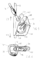
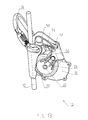
- la figure 13 est une vue en perspective d'une variante de réalisation à volet de sécurité ;
- la figure 14 est une vue identique de la figure 13 lors de l'ouverture du bras support pour la mise en place de la corde ;
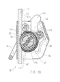
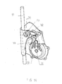
- les figures 15 à 17 sont des vues partiellement arrachées de la figure 13, respectivement après mise en place de la corde, en position de fonctionnement normal, et en position de blocage.
- Figure 1 is a perspective view of the fall arrest device according to the invention, which is installed on a lifeline after installation of a carabiner attachment;
- Figure 2 shows an exploded perspective view of the fall arrest apparatus of Figure 1, the mechanical coupling being shown in the disengaged position within the roller;
- Figure 3 is a left view of Figure 2, after disassembly of the weights;
- Figure 4 shows an elevational view of the apparatus after opening the restraint system for the passage of the rope;
- Figure 5 is an identical view of Figure 4, and shows the normal use position rise or fall after installation of the carabiner;
- Figure 6 is a top view of Figure 5;
- Figure 7 is a vertical sectional view of Figure 5;
- Figures 8 and 9 are sectional views along the lines 8-8 and 9-9 of Figure 7;
- Figure 10 shows an identical view of Figure 7, the apparatus being in the blocking position following a fall;
- Figure 11 shows the anti-safety opening position following the abutment of the retaining system against the carabiner;
- Figure 12 is a sectional view of Figure 4, the stop being in a position preventing the introduction of the carabiner;
- Figure 13 is a perspective view of an alternative embodiment with safety flap;
- Figure 14 is an identical view of Figure 13 when opening the support arm for the establishment of the rope;
- Figures 15 to 17 are partially cutaway views of Figure 13, respectively after implementation of the rope, in the normal operating position, and in the locking position.
Sur les figures 1 à 12, un dispositif antichute 10 est utilisé pour la sécurité d'une
personne se déplaçant le long d'une corde 12 fixe d'assurance. Un mousqueton
14 est accroché au dispositif antichute 10 de manière à être relié au baudrier, soit
en direct, soit par l'intermédiaire d'une longe à absorption.In FIGS. 1 to 12, a
Lors de l'utilisation normale de montée ou de descente, le dispositif antichute 10
suit la progression de la personne le long de la corde 12 sans engendrer de
blocage. La personne est libre de se déplacer sans aucune intervention
manuelle de déblocage du dispositif antichute 10.During normal use of ascent or descent, the
Le dispositif antichute 10 est composé d'un corps 16 rigide et d'un système de
retenue 18 mobile coopérant avec la corde 12 pour occuper soit une position
active de blocage en cas de chute, soit une position inactive de déblocage dans
le sens de la montée, ou dans le sens opposé lors d'une descente contrôlée.The
Le corps 16 de préférence métallique, comporte une goulotte 20 rectiligne en
forme de U pour le passage de la corde 12, et un étrier 22 pour le montage d'un
premier axe 24 s'étendant transversalement par rapport à la direction de la
goulotte 20. La partie supérieure de la goulotte 20 est percée par deux trous 23
pour autoriser le passage du mousqueton 14 d'attache au baudrier.The
L'organe de retenue 18 comprend un bras support 26 articulé sur le premier axe
24, et un galet 28 en forme de roue montée à rotation libre sur un deuxième axe
30 solidaire du bras support 26. La surface périphérique du galet 28 est
cylindrique, et est munie d'une pluralité de picots 32 ayant chacun une inclinaison
prédéterminée par rapport à la direction radiale passant par l'axe 30. Un ressort
de torsion (non représenté) est enfilé sur le premier axe 24 et sollicite le bras
support 26 en direction de la goulotte 20.The retaining
Le galet 28 est doté d'un organe d'entraínement 33 interne, percé par un orifice
34 central cylindrique, lequel est traversé par un coussinet 36 tubulaire introduit
sur le deuxième axe 30 fixe. A l'intérieur du galet 28 se trouve en plus un
accouplement mécanique 38 formé par une paire de masselottes 40
cylindriques agencées entre des rampes 42 opposées de l'organe
d'entraínement 33 et un rebord 44 circulaire du bras support 26.The
A chaque masselotte 40 est associé un ressort 46 en forme d'épingle destiné à
solliciter l'accouplement mécanique 38 vers la position débrayée lors de
l'utilisation normale du dispositif antichute 10. Dans cet état de repos, les
masselottes 40 se trouvent dans un creux de l'organe d'entraínement 33, de
manière à interrompre l'accouplement mécanique 38 entre le galet 28 et le bras
support 26. Le galet 28 est alors entraíné en rotation par la friction de la corde 12,
tandis que le bras support 26 est en position inactive permettant au dispositif
antichute 10 de suivre la progression de l'utilisateur à la montée ou à la descente.Each
La force de rappel des ressorts 46 définit le seuil d'accouplement en fonction de
la vitesse ou de l'accélération de l'organe d'entraínement 33 du galet 28 rotatif.
En cas de chute, la rotation brusque du galet 28 sur l'axe 30 provoque le
déplacement des masselottes 40 par effet centrifuge vers la position embrayée.
Ce déplacement s'effectue à l'encontre de la force de rappel des ressorts 46, et
engendre un coincement des masselottes 40 entre le rebord 44 et l'organe
d'entraínement 33. L'accouplement mécanique en position embrayée rend ainsi
le galet 28 solidaire du bras support 26, de manière à constituer un taquet
coinceur susceptible de pivoter autour du premier axe 24, et de bloquer la chute
par blocage de la corde 12.The restoring force of the
Le bras support 26 pivotant est équipé d'une butée 48 destinée à coopérer
avec le mousqueton 14 pour limiter la course de pivotement du bras 26 dans la
position inactive de déblocage. Le temps de réponse du bras support 26
pivotant est ainsi réduit au minimum pour obtenir le blocage en cas de chute.
L'extrémité de la butée 48 est pourvue d'une protubérance 49 destinée à
s'intercaler entre les deux trous 23 du corps 16 pour empêcher la mise en place
du mousqueton 14 avant l'introduction de la corde 12.The pivoting
Le fonctionnement du dispositif antichute 10 selon les figures 1 à 12 est le
suivant:
En référence à la figure 10 correspondant à une position de blocage sur chute de
l'utilisateur, la rotation brusque du galet et de l'organe d'entraínement 33 dans le
sens horaire soumet les masselottes 40 à une force centrifuge, laquelle est
supérieure et de sens opposé à la force de rappel des ressorts 46. Les
masselottes 40 se déplacent sur les rampes 42, ce qui provoque un coincement
des masselottes 40 entre le rebord 44 et l'organe d'entraínement 33.
L'accouplement mécanique se trouve alors en position embrayée en rendant le
galet 28 solidaire du bras support 26. L'ensemble constitue un taquet coinceur
susceptible de pivoter dans le sens horaire autour du premier axe 24, et de
bloquer la chute par blocage de la corde 12. Le déblocage des masselottes 40
intervient par une action manuelle de l'opérateur consistant à maintenir le galet 28
contre la corde 12, et en faisant remonter le corps 16 de quelques centimètres.Referring to Figure 10 corresponding to a locking position on a fall of
the user, the abrupt rotation of the roller and the
Sur la figure 11, on remarque qu'en position d'utilisation normale du dispositif
antichute 10, la butée 48 est en appui contre le mousqueton 14 pour limiter la
course de pivotement du bras 26 dans la position inactive de déblocage. Le
temps de réponse pour le blocage est ainsi réduit en cas de chute.In FIG. 11, it can be seen that in the position of normal use of the
Selon le développement de l'invention illustré aux figures 13 à 17, la butée 48
est remplacée par un volet de sécurité 50, lequel est agencé pour remplir les
mêmes fonctions de la butée 48 des figures 1-12 précédentes, avec en plus
une fonction de positionnement de la corde 12 au fond de la goulotte 20 avant
l'introduction du mousqueton 14 dans les trous 23.According to the development of the invention illustrated in FIGS. 13 to 17, the
Le volet de sécurité 50 est monté à pivotement sur un axe 52, et comporte une
ouverture 54 oblongue à l'intérieur de laquelle se déplace un levier de
commande 56 solidaire du bras support 26. L'ouverture 54 présente une
double rampe coudée destinée à déplacer le volet 50 en fonction du
mouvement de pivotement du bras 26. Le volet 50 comprend en plus une aile
58 destinée à plaquer la corde 12 au fond de la goulotte 20.The
Le fonctionnement du volet de sécurité 50 selon les figures 14 à 17 est le
suivant :
Claims (8)
Applications Claiming Priority (2)
| Application Number | Priority Date | Filing Date | Title |
|---|---|---|---|
| FR0208865A FR2842113B1 (en) | 2002-07-12 | 2002-07-12 | FOLLOWING FALL ARRANGEMENT FOR FIXED ROPE |
| FR0208865 | 2002-07-12 |
Publications (2)
| Publication Number | Publication Date |
|---|---|
| EP1380320A1 true EP1380320A1 (en) | 2004-01-14 |
| EP1380320B1 EP1380320B1 (en) | 2005-05-18 |
Family
ID=29725322
Family Applications (1)
| Application Number | Title | Priority Date | Filing Date |
|---|---|---|---|
| EP03354059A Expired - Lifetime EP1380320B1 (en) | 2002-07-12 | 2003-06-19 | Fall protection follower device along a fixed rope |
Country Status (7)
| Country | Link |
|---|---|
| US (1) | US6793046B2 (en) |
| EP (1) | EP1380320B1 (en) |
| JP (1) | JP4242222B2 (en) |
| AT (1) | ATE295753T1 (en) |
| DE (1) | DE60300667T2 (en) |
| ES (1) | ES2242934T3 (en) |
| FR (1) | FR2842113B1 (en) |
Cited By (11)
| Publication number | Priority date | Publication date | Assignee | Title |
|---|---|---|---|---|
| WO2011050881A1 (en) * | 2009-10-30 | 2011-05-05 | Skylotec Gmbh | Catching device having a speed-dependent coupling |
| CN103328318A (en) * | 2011-01-19 | 2013-09-25 | 力特亿泽公司 | Self-locking clip systems and methods |
| EP2754465A1 (en) | 2013-01-15 | 2014-07-16 | Zedel | Fall-arresting and rope-blocking safety apparatus |
| CN103920258A (en) * | 2013-01-15 | 2014-07-16 | 齐德公司 | Fall Arrest Safety Apparatus On Rope With Clamping Function |
| CN105073204A (en) * | 2013-02-22 | 2015-11-18 | 凯比特安全设备集团(北欧)有限公司 | Fall arrest device |
| CN107191515A (en) * | 2017-05-19 | 2017-09-22 | 中建八局第二建设有限公司 | A kind of centrifugal hanging hook overspeed control device |
| CN111706061A (en) * | 2020-05-26 | 2020-09-25 | 深圳市特辰科技股份有限公司 | Anti-falling climbing frame for centrifugal rotating wheel |
| FR3095952A1 (en) | 2019-05-14 | 2020-11-20 | Zedel | WIRED ELEMENT STRAND ENERGY ABSORBER DEVICE |
| CN112827088A (en) * | 2020-12-31 | 2021-05-25 | 贵州电网有限责任公司 | Side joint formula climbing device |
| CN115738111A (en) * | 2022-12-09 | 2023-03-07 | 李国栋 | Automatic slowly-descending rock climbing protection device |
| FR3139725A1 (en) * | 2022-09-19 | 2024-03-22 | Zedel | DEVICE FOR DETECTING A THRESHOLD SPEED OF A BLOCKING DEVICE, BLOCKING DEVICE AND METHOD FOR BLOCKING A WIRED ELEMENT |
Families Citing this family (30)
| Publication number | Priority date | Publication date | Assignee | Title |
|---|---|---|---|---|
| US6948586B1 (en) * | 2003-05-19 | 2005-09-27 | Axian Technology, Inc. | Quick release rappel device |
| US6907960B2 (en) * | 2003-09-18 | 2005-06-21 | Gregory Lee Klingler | Safe auto-locking belay override mechanism |
| FR2860982B1 (en) * | 2003-10-20 | 2006-01-20 | Zedel | ANTI-FALLING DEVICE WITH BLOCKING ROLL |
| FR2898813B1 (en) | 2006-03-22 | 2013-07-19 | Olivier Miceli | FALLING ANTI FALLING DEVICE |
| US20100181142A1 (en) * | 2009-01-16 | 2010-07-22 | Gerner Mark H | Method and Apparatus for Climbing |
| CN101884827B (en) * | 2009-05-14 | 2012-05-23 | 刘晓海 | Double-locking high-altitude working anti-dropping safety device |
| US8348016B2 (en) * | 2009-08-26 | 2013-01-08 | Lewis Richard W | Descender with fall arrest and controlled rate of descent |
| KR101025183B1 (en) * | 2010-09-27 | 2011-04-07 | (주) 선원 밸브 | Snap ring |
| IT1403628B1 (en) * | 2011-01-13 | 2013-10-31 | Aludesign Spa | INSURER AND DISCENSOR DEVICE |
| WO2013104139A1 (en) * | 2012-01-13 | 2013-07-18 | He Shaodun | Rope anti-reverse device for suspension descending system |
| FR3000898B1 (en) * | 2013-01-16 | 2015-06-26 | Zedel | SAFETY APPARATUS ON ROPE HAVING A INDICATING INDICATOR INDICATOR STATE INDICATOR FOR CLOSING FLASKS |
| US9623269B2 (en) * | 2013-03-14 | 2017-04-18 | Black Diamond Equipment, Ltd. | Systems for assisted braking belay with a cam-clutch mechanism |
| US9320924B2 (en) | 2013-03-15 | 2016-04-26 | Honeywell International Inc. | Self-locking webbing connectable device attachment plate |
| EP3129317B1 (en) * | 2014-04-07 | 2020-03-18 | Actsafe Systems AB | Portable power driven system comprising a rope grab arrangement |
| FR3023726B1 (en) * | 2014-07-18 | 2016-07-29 | Zedel | BLOCKER FOR ROPE UP |
| US9750959B2 (en) * | 2015-10-21 | 2017-09-05 | Msa Technology, Llc | Cable grab device |
| EP3655613A4 (en) * | 2017-07-17 | 2021-04-07 | SafeWorks, LLC | Climb assist and fall arrest system |
| US20190338593A1 (en) * | 2017-07-17 | 2019-11-07 | Safeworks, Llc | Integrated climb assist and fall arrest systems and methods |
| USD869939S1 (en) * | 2018-07-17 | 2019-12-17 | Zedel | Rope climbing apparatus |
| USD878185S1 (en) * | 2018-07-17 | 2020-03-17 | Zedel | Mechanical prusik |
| CN109939376B (en) * | 2019-03-12 | 2020-10-16 | 无锡市钱桥建筑安装工程有限公司 | Cableway escape device for high-rise building |
| CN114729676A (en) * | 2019-07-16 | 2022-07-08 | 安全工业责任有限公司 | Rope connection |
| DE102020107829A1 (en) | 2020-03-21 | 2021-09-23 | Edelrid Gmbh & Co. Kg | Revolving lifeline device |
| EP3939670A1 (en) | 2020-07-13 | 2022-01-19 | Tractel Greifzug GmbH | Fall arrest device |
| CN111840851A (en) * | 2020-08-18 | 2020-10-30 | 中际联合(北京)科技股份有限公司 | Rope locking device |
| US20220176173A1 (en) * | 2020-12-07 | 2022-06-09 | Werner Co. | Self-retracting lifeline housing |
| US20220403916A1 (en) * | 2021-06-17 | 2022-12-22 | Daniel Scott | Universal tie-down apparatus and method of use |
| US11779780B1 (en) * | 2022-11-30 | 2023-10-10 | William Burke | Controlled ascender/descender device |
| CN113847389B (en) * | 2021-09-29 | 2023-04-18 | 广东电网有限责任公司 | A couple is prevented weighing down by heavy object for shaft tower operation |
| WO2023152462A1 (en) * | 2022-02-09 | 2023-08-17 | International Safety Components Ltd | Fall- arrest devices |
Citations (5)
| Publication number | Priority date | Publication date | Assignee | Title |
|---|---|---|---|---|
| GB1131310A (en) * | 1965-11-25 | 1968-10-23 | Barrow Hepburn & Gale Ltd | Safety device for arresting workers at height, in the event of a fall |
| US4923037A (en) | 1989-06-29 | 1990-05-08 | John Stephenson | Fall arrest device |
| US5323873A (en) * | 1992-03-18 | 1994-06-28 | Societe Anonyme Dite: Komet | Safety device |
| US6056086A (en) * | 1996-07-16 | 2000-05-02 | Tractel, S.A. | Device for automatically stopping the fall of personnel working high above ground |
| WO2000024471A1 (en) | 1998-10-23 | 2000-05-04 | Latchways Plc | Two-way locking device for height safety apparatus |
Family Cites Families (8)
| Publication number | Priority date | Publication date | Assignee | Title |
|---|---|---|---|---|
| US2080700A (en) * | 1935-12-04 | 1937-05-18 | Orie O Dale | Line grip |
| US3811155A (en) * | 1972-06-21 | 1974-05-21 | L Stafford | Rope grab assembly |
| US3852943A (en) * | 1973-08-27 | 1974-12-10 | Meyer Ind Inc | Portable safety clamp |
| US4077094A (en) * | 1976-09-17 | 1978-03-07 | Swager William E | Clamping device for a rope, cable, annular bar, or the like |
| US4542884A (en) * | 1983-06-06 | 1985-09-24 | Dodge Jr Cleveland E | Removable double action rope grip |
| US4941548A (en) * | 1989-11-17 | 1990-07-17 | Blanchard Mark W | Fall arresting device for climbers |
| US5156240A (en) * | 1991-05-31 | 1992-10-20 | Meyer Ostrobrod | Rope grab |
| US5855251A (en) * | 1997-01-22 | 1999-01-05 | Deuer; Joseph F. | Security device for use with a safety line |
-
2002
- 2002-07-12 FR FR0208865A patent/FR2842113B1/en not_active Expired - Fee Related
-
2003
- 2003-06-19 AT AT03354059T patent/ATE295753T1/en active
- 2003-06-19 DE DE60300667T patent/DE60300667T2/en not_active Expired - Lifetime
- 2003-06-19 EP EP03354059A patent/EP1380320B1/en not_active Expired - Lifetime
- 2003-06-19 ES ES03354059T patent/ES2242934T3/en not_active Expired - Lifetime
- 2003-07-08 US US10/614,515 patent/US6793046B2/en not_active Expired - Lifetime
- 2003-07-14 JP JP2003196470A patent/JP4242222B2/en not_active Expired - Fee Related
Patent Citations (5)
| Publication number | Priority date | Publication date | Assignee | Title |
|---|---|---|---|---|
| GB1131310A (en) * | 1965-11-25 | 1968-10-23 | Barrow Hepburn & Gale Ltd | Safety device for arresting workers at height, in the event of a fall |
| US4923037A (en) | 1989-06-29 | 1990-05-08 | John Stephenson | Fall arrest device |
| US5323873A (en) * | 1992-03-18 | 1994-06-28 | Societe Anonyme Dite: Komet | Safety device |
| US6056086A (en) * | 1996-07-16 | 2000-05-02 | Tractel, S.A. | Device for automatically stopping the fall of personnel working high above ground |
| WO2000024471A1 (en) | 1998-10-23 | 2000-05-04 | Latchways Plc | Two-way locking device for height safety apparatus |
Cited By (16)
| Publication number | Priority date | Publication date | Assignee | Title |
|---|---|---|---|---|
| WO2011050881A1 (en) * | 2009-10-30 | 2011-05-05 | Skylotec Gmbh | Catching device having a speed-dependent coupling |
| CN103328318A (en) * | 2011-01-19 | 2013-09-25 | 力特亿泽公司 | Self-locking clip systems and methods |
| US9498660B2 (en) | 2013-01-15 | 2016-11-22 | Zedel | Fall arrest safety apparatus on a rope with clamping function |
| CN103920258B (en) * | 2013-01-15 | 2019-09-10 | 齐德公司 | The falling for clamping function that have on rope prevents safety device |
| EP2754466A1 (en) | 2013-01-15 | 2014-07-16 | Zedel | Fall-arresting safety apparatus on a rope with blocking function |
| FR3000900A1 (en) * | 2013-01-15 | 2014-07-18 | Zedel | SAFETY DEVICE FALLING ON ROPE WITH BLOCKING FUNCTION |
| US9192792B2 (en) | 2013-01-15 | 2015-11-24 | Zedel | Fall arrest safety apparatus with blocking on a rope |
| EP2754465A1 (en) | 2013-01-15 | 2014-07-16 | Zedel | Fall-arresting and rope-blocking safety apparatus |
| CN103920258A (en) * | 2013-01-15 | 2014-07-16 | 齐德公司 | Fall Arrest Safety Apparatus On Rope With Clamping Function |
| CN105073204A (en) * | 2013-02-22 | 2015-11-18 | 凯比特安全设备集团(北欧)有限公司 | Fall arrest device |
| CN107191515A (en) * | 2017-05-19 | 2017-09-22 | 中建八局第二建设有限公司 | A kind of centrifugal hanging hook overspeed control device |
| FR3095952A1 (en) | 2019-05-14 | 2020-11-20 | Zedel | WIRED ELEMENT STRAND ENERGY ABSORBER DEVICE |
| CN111706061A (en) * | 2020-05-26 | 2020-09-25 | 深圳市特辰科技股份有限公司 | Anti-falling climbing frame for centrifugal rotating wheel |
| CN112827088A (en) * | 2020-12-31 | 2021-05-25 | 贵州电网有限责任公司 | Side joint formula climbing device |
| FR3139725A1 (en) * | 2022-09-19 | 2024-03-22 | Zedel | DEVICE FOR DETECTING A THRESHOLD SPEED OF A BLOCKING DEVICE, BLOCKING DEVICE AND METHOD FOR BLOCKING A WIRED ELEMENT |
| CN115738111A (en) * | 2022-12-09 | 2023-03-07 | 李国栋 | Automatic slowly-descending rock climbing protection device |
Also Published As
| Publication number | Publication date |
|---|---|
| JP4242222B2 (en) | 2009-03-25 |
| FR2842113A1 (en) | 2004-01-16 |
| EP1380320B1 (en) | 2005-05-18 |
| JP2004144292A (en) | 2004-05-20 |
| US20040020727A1 (en) | 2004-02-05 |
| DE60300667D1 (en) | 2005-06-23 |
| ES2242934T3 (en) | 2005-11-16 |
| DE60300667T2 (en) | 2006-04-27 |
| US6793046B2 (en) | 2004-09-21 |
| FR2842113B1 (en) | 2004-09-24 |
| ATE295753T1 (en) | 2005-06-15 |
Similar Documents
| Publication | Publication Date | Title |
|---|---|---|
| EP1380320B1 (en) | Fall protection follower device along a fixed rope | |
| EP1525903B1 (en) | Fall arrest device with blocking catch | |
| EP2754466B1 (en) | Fall-arresting safety apparatus on a rope with blocking function | |
| EP2754465B1 (en) | Fall-arresting and rope-blocking safety apparatus | |
| EP3056248B1 (en) | Descender device on rope with gear reduction and panic lock | |
| CA2231722C (en) | Device for automatically stopping the fall of personnel working high above ground | |
| EP2191870B1 (en) | Blocking device with cam for belaying a fixed rope | |
| EP0593369B1 (en) | Security descending device for rope | |
| EP0416079B1 (en) | Self-locking descending device for rope with two locking positions | |
| EP2257343B1 (en) | Apparatus for securing rescue operations by helihoisting | |
| EP0803268B1 (en) | Pulley with pivoting side plate and integral clamp | |
| EP0752255B1 (en) | Mobile fall arrest device for flexible safety rope | |
| EP0398819B1 (en) | Self arresting rope safety device | |
| FR2721522A1 (en) | Self-locking descender with self-locking rope. | |
| CA2180440C (en) | Fall-arresting safety apparatus | |
| EP1834672A1 (en) | Multifunctional belay device for rope | |
| EP2192959B1 (en) | Follow-up fall prevention device | |
| EP3124081B1 (en) | Belay device on rope for use in belay and toprope mode | |
| FR2954912A1 (en) | Anti-fall apparatus for assuring cord during working in heights, has control lever operated in load state of apparatus to move apart blocking device with respect to bottom of chute that progressively releases cam device | |
| WO2003037708A1 (en) | Releasable hook system | |
| FR2898813A1 (en) | Fall arrest device for saving e.g. climber, has body equipped with occupant locking system that includes cavity with flyweight, where flyweight is provided in contact with lifeline during controlled movement of lifeline | |
| FR2877584A3 (en) | Emergency rescue device for tower building, has pin moving itself with respect to movable handle to regulate size of interval that is formed by open passage of movable handle and intended for passage of rope |
Legal Events
| Date | Code | Title | Description |
|---|---|---|---|
| PUAI | Public reference made under article 153(3) epc to a published international application that has entered the european phase |
Free format text: ORIGINAL CODE: 0009012 |
|
| AK | Designated contracting states |
Kind code of ref document: A1 Designated state(s): AT BE BG CH CY CZ DE DK EE ES FI FR GB GR HU IE IT LI LU MC NL PT RO SE SI SK TR |
|
| AX | Request for extension of the european patent |
Extension state: AL LT LV MK |
|
| 17P | Request for examination filed |
Effective date: 20040705 |
|
| AKX | Designation fees paid |
Designated state(s): AT BE BG CH CY CZ DE DK EE ES FI FR GB GR HU IE IT LI LU MC NL PT RO SE SI SK TR |
|
| GRAP | Despatch of communication of intention to grant a patent |
Free format text: ORIGINAL CODE: EPIDOSNIGR1 |
|
| GRAS | Grant fee paid |
Free format text: ORIGINAL CODE: EPIDOSNIGR3 |
|
| GRAA | (expected) grant |
Free format text: ORIGINAL CODE: 0009210 |
|
| AK | Designated contracting states |
Kind code of ref document: B1 Designated state(s): AT BE BG CH CY CZ DE DK EE ES FI FR GB GR HU IE IT LI LU MC NL PT RO SE SI SK TR |
|
| PG25 | Lapsed in a contracting state [announced via postgrant information from national office to epo] |
Ref country code: RO Free format text: LAPSE BECAUSE OF FAILURE TO SUBMIT A TRANSLATION OF THE DESCRIPTION OR TO PAY THE FEE WITHIN THE PRESCRIBED TIME-LIMIT Effective date: 20050518 Ref country code: IE Free format text: LAPSE BECAUSE OF FAILURE TO SUBMIT A TRANSLATION OF THE DESCRIPTION OR TO PAY THE FEE WITHIN THE PRESCRIBED TIME-LIMIT Effective date: 20050518 Ref country code: SK Free format text: LAPSE BECAUSE OF FAILURE TO SUBMIT A TRANSLATION OF THE DESCRIPTION OR TO PAY THE FEE WITHIN THE PRESCRIBED TIME-LIMIT Effective date: 20050518 Ref country code: TR Free format text: LAPSE BECAUSE OF FAILURE TO SUBMIT A TRANSLATION OF THE DESCRIPTION OR TO PAY THE FEE WITHIN THE PRESCRIBED TIME-LIMIT Effective date: 20050518 Ref country code: SI Free format text: LAPSE BECAUSE OF FAILURE TO SUBMIT A TRANSLATION OF THE DESCRIPTION OR TO PAY THE FEE WITHIN THE PRESCRIBED TIME-LIMIT Effective date: 20050518 Ref country code: EE Free format text: LAPSE BECAUSE OF FAILURE TO SUBMIT A TRANSLATION OF THE DESCRIPTION OR TO PAY THE FEE WITHIN THE PRESCRIBED TIME-LIMIT Effective date: 20050518 Ref country code: NL Free format text: LAPSE BECAUSE OF FAILURE TO SUBMIT A TRANSLATION OF THE DESCRIPTION OR TO PAY THE FEE WITHIN THE PRESCRIBED TIME-LIMIT Effective date: 20050518 Ref country code: FI Free format text: LAPSE BECAUSE OF FAILURE TO SUBMIT A TRANSLATION OF THE DESCRIPTION OR TO PAY THE FEE WITHIN THE PRESCRIBED TIME-LIMIT Effective date: 20050518 |
|
| REG | Reference to a national code |
Ref country code: GB Ref legal event code: FG4D Free format text: NOT ENGLISH |
|
| REG | Reference to a national code |
Ref country code: CH Ref legal event code: EP |
|
| REG | Reference to a national code |
Ref country code: IE Ref legal event code: FG4D Free format text: LANGUAGE OF EP DOCUMENT: FRENCH |
|
| PG25 | Lapsed in a contracting state [announced via postgrant information from national office to epo] |
Ref country code: LU Free format text: LAPSE BECAUSE OF NON-PAYMENT OF DUE FEES Effective date: 20050619 Ref country code: CY Free format text: LAPSE BECAUSE OF FAILURE TO SUBMIT A TRANSLATION OF THE DESCRIPTION OR TO PAY THE FEE WITHIN THE PRESCRIBED TIME-LIMIT Effective date: 20050619 Ref country code: CZ Free format text: LAPSE BECAUSE OF NON-PAYMENT OF DUE FEES Effective date: 20050619 |
|
| REF | Corresponds to: |
Ref document number: 60300667 Country of ref document: DE Date of ref document: 20050623 Kind code of ref document: P |
|
| PG25 | Lapsed in a contracting state [announced via postgrant information from national office to epo] |
Ref country code: BE Free format text: LAPSE BECAUSE OF NON-PAYMENT OF DUE FEES Effective date: 20050630 Ref country code: MC Free format text: LAPSE BECAUSE OF NON-PAYMENT OF DUE FEES Effective date: 20050630 |
|
| PG25 | Lapsed in a contracting state [announced via postgrant information from national office to epo] |
Ref country code: GR Free format text: LAPSE BECAUSE OF FAILURE TO SUBMIT A TRANSLATION OF THE DESCRIPTION OR TO PAY THE FEE WITHIN THE PRESCRIBED TIME-LIMIT Effective date: 20050818 Ref country code: SE Free format text: LAPSE BECAUSE OF FAILURE TO SUBMIT A TRANSLATION OF THE DESCRIPTION OR TO PAY THE FEE WITHIN THE PRESCRIBED TIME-LIMIT Effective date: 20050818 Ref country code: BG Free format text: LAPSE BECAUSE OF FAILURE TO SUBMIT A TRANSLATION OF THE DESCRIPTION OR TO PAY THE FEE WITHIN THE PRESCRIBED TIME-LIMIT Effective date: 20050818 Ref country code: DK Free format text: LAPSE BECAUSE OF FAILURE TO SUBMIT A TRANSLATION OF THE DESCRIPTION OR TO PAY THE FEE WITHIN THE PRESCRIBED TIME-LIMIT Effective date: 20050818 |
|
| GBT | Gb: translation of ep patent filed (gb section 77(6)(a)/1977) |
Effective date: 20050920 |
|
| PG25 | Lapsed in a contracting state [announced via postgrant information from national office to epo] |
Ref country code: PT Free format text: LAPSE BECAUSE OF FAILURE TO SUBMIT A TRANSLATION OF THE DESCRIPTION OR TO PAY THE FEE WITHIN THE PRESCRIBED TIME-LIMIT Effective date: 20051024 |
|
| REG | Reference to a national code |
Ref country code: ES Ref legal event code: FG2A Ref document number: 2242934 Country of ref document: ES Kind code of ref document: T3 |
|
| PG25 | Lapsed in a contracting state [announced via postgrant information from national office to epo] |
Ref country code: HU Free format text: LAPSE BECAUSE OF FAILURE TO SUBMIT A TRANSLATION OF THE DESCRIPTION OR TO PAY THE FEE WITHIN THE PRESCRIBED TIME-LIMIT Effective date: 20051119 |
|
| NLV1 | Nl: lapsed or annulled due to failure to fulfill the requirements of art. 29p and 29m of the patents act | ||
| REG | Reference to a national code |
Ref country code: IE Ref legal event code: FD4D |
|
| PLBE | No opposition filed within time limit |
Free format text: ORIGINAL CODE: 0009261 |
|
| STAA | Information on the status of an ep patent application or granted ep patent |
Free format text: STATUS: NO OPPOSITION FILED WITHIN TIME LIMIT |
|
| 26N | No opposition filed |
Effective date: 20060221 |
|
| BERE | Be: lapsed |
Owner name: ZEDEL Effective date: 20050630 |
|
| REG | Reference to a national code |
Ref country code: CH Ref legal event code: PL |
|
| PG25 | Lapsed in a contracting state [announced via postgrant information from national office to epo] |
Ref country code: LI Free format text: LAPSE BECAUSE OF NON-PAYMENT OF DUE FEES Effective date: 20050630 Ref country code: CH Free format text: LAPSE BECAUSE OF NON-PAYMENT OF DUE FEES Effective date: 20050630 |
|
| PG25 | Lapsed in a contracting state [announced via postgrant information from national office to epo] |
Ref country code: LI Free format text: LAPSE BECAUSE OF NON-PAYMENT OF DUE FEES Effective date: 20070630 Ref country code: CH Free format text: LAPSE BECAUSE OF NON-PAYMENT OF DUE FEES Effective date: 20070630 |
|
| PGFP | Annual fee paid to national office [announced via postgrant information from national office to epo] |
Ref country code: ES Payment date: 20110715 Year of fee payment: 9 |
|
| REG | Reference to a national code |
Ref country code: ES Ref legal event code: FD2A Effective date: 20131018 |
|
| PG25 | Lapsed in a contracting state [announced via postgrant information from national office to epo] |
Ref country code: ES Free format text: LAPSE BECAUSE OF NON-PAYMENT OF DUE FEES Effective date: 20120620 |
|
| REG | Reference to a national code |
Ref country code: FR Ref legal event code: PLFP Year of fee payment: 14 |
|
| REG | Reference to a national code |
Ref country code: FR Ref legal event code: PLFP Year of fee payment: 15 |
|
| REG | Reference to a national code |
Ref country code: FR Ref legal event code: PLFP Year of fee payment: 16 |
|
| PGFP | Annual fee paid to national office [announced via postgrant information from national office to epo] |
Ref country code: IT Payment date: 20210511 Year of fee payment: 19 Ref country code: DE Payment date: 20210525 Year of fee payment: 19 |
|
| PGFP | Annual fee paid to national office [announced via postgrant information from national office to epo] |
Ref country code: AT Payment date: 20210525 Year of fee payment: 19 Ref country code: GB Payment date: 20210526 Year of fee payment: 19 |
|
| PGFP | Annual fee paid to national office [announced via postgrant information from national office to epo] |
Ref country code: FR Payment date: 20220408 Year of fee payment: 20 |
|
| REG | Reference to a national code |
Ref country code: DE Ref legal event code: R119 Ref document number: 60300667 Country of ref document: DE |
|
| REG | Reference to a national code |
Ref country code: AT Ref legal event code: MM01 Ref document number: 295753 Country of ref document: AT Kind code of ref document: T Effective date: 20220619 |
|
| GBPC | Gb: european patent ceased through non-payment of renewal fee |
Effective date: 20220619 |
|
| PG25 | Lapsed in a contracting state [announced via postgrant information from national office to epo] |
Ref country code: AT Free format text: LAPSE BECAUSE OF NON-PAYMENT OF DUE FEES Effective date: 20220619 |
|
| PG25 | Lapsed in a contracting state [announced via postgrant information from national office to epo] |
Ref country code: GB Free format text: LAPSE BECAUSE OF NON-PAYMENT OF DUE FEES Effective date: 20220619 Ref country code: DE Free format text: LAPSE BECAUSE OF NON-PAYMENT OF DUE FEES Effective date: 20230103 |
|
| PG25 | Lapsed in a contracting state [announced via postgrant information from national office to epo] |
Ref country code: IT Free format text: LAPSE BECAUSE OF NON-PAYMENT OF DUE FEES Effective date: 20220619 |