EP1379902B1 - Adjustment method, especially a laser adjustment method, and corresponding actuator - Google Patents
Adjustment method, especially a laser adjustment method, and corresponding actuator Download PDFInfo
- Publication number
- EP1379902B1 EP1379902B1 EP02740258A EP02740258A EP1379902B1 EP 1379902 B1 EP1379902 B1 EP 1379902B1 EP 02740258 A EP02740258 A EP 02740258A EP 02740258 A EP02740258 A EP 02740258A EP 1379902 B1 EP1379902 B1 EP 1379902B1
- Authority
- EP
- European Patent Office
- Prior art keywords
- actuator
- temperature
- part region
- partial region
- heated
- Prior art date
- Legal status (The legal status is an assumption and is not a legal conclusion. Google has not performed a legal analysis and makes no representation as to the accuracy of the status listed.)
- Expired - Lifetime
Links
Images

Classifications
-
- G—PHYSICS
- G02—OPTICS
- G02B—OPTICAL ELEMENTS, SYSTEMS OR APPARATUS
- G02B6/00—Light guides; Structural details of arrangements comprising light guides and other optical elements, e.g. couplings
- G02B6/24—Coupling light guides
- G02B6/42—Coupling light guides with opto-electronic elements
- G02B6/4201—Packages, e.g. shape, construction, internal or external details
- G02B6/4219—Mechanical fixtures for holding or positioning the elements relative to each other in the couplings; Alignment methods for the elements, e.g. measuring or observing methods especially used therefor
- G02B6/422—Active alignment, i.e. moving the elements in response to the detected degree of coupling or position of the elements
- G02B6/4226—Positioning means for moving the elements into alignment, e.g. alignment screws, deformation of the mount
-
- G—PHYSICS
- G02—OPTICS
- G02B—OPTICAL ELEMENTS, SYSTEMS OR APPARATUS
- G02B6/00—Light guides; Structural details of arrangements comprising light guides and other optical elements, e.g. couplings
- G02B6/24—Coupling light guides
- G02B6/36—Mechanical coupling means
- G02B6/38—Mechanical coupling means having fibre to fibre mating means
- G02B6/3801—Permanent connections, i.e. wherein fibres are kept aligned by mechanical means
- G02B6/3803—Adjustment or alignment devices for alignment prior to splicing
-
- G—PHYSICS
- G02—OPTICS
- G02B—OPTICAL ELEMENTS, SYSTEMS OR APPARATUS
- G02B6/00—Light guides; Structural details of arrangements comprising light guides and other optical elements, e.g. couplings
- G02B6/24—Coupling light guides
- G02B6/36—Mechanical coupling means
- G02B6/3628—Mechanical coupling means for mounting fibres to supporting carriers
- G02B6/3648—Supporting carriers of a microbench type, i.e. with micromachined additional mechanical structures
- G02B6/366—Supporting carriers of a microbench type, i.e. with micromachined additional mechanical structures the additional structures allowing for adjustment or alignment in all dimensions, i.e. 3D microoptics arrangements, e.g. free space optics on the microbench, microhinges or spring latches, with associated microactuating elements for fine adjustment or alignment
Abstract
Description
Die Erfindung betrifft ein Justierverfahren, insbesondere für das Justieren optischer oder faseroptischer Komponenten mit den Merkmalen des Oberbegriffs des Patentanspruchs 1. Des Weiteren betrifft die Erfindung einen hierfür geeigneten Aktor.The invention relates to an adjustment method, in particular for the adjustment of optical or fiber-optic components with the features of the preamble of
Für das hochgenaue Justieren, beispielsweise für Komponenten der Mikromechanik, wurden in jüngerer Zeit Laser-Justierverfahren und hierfür geeignete Aktoren entwickelt.For highly precise adjustment, for example for components of micromechanics, laser alignment methods and actuators suitable for this purpose have recently been developed.
Das Grundprinzip des Laserjustierens besteht darin, einen vorbestimmten Bereich eines Aktors mittels eines hochenergetischen, vorzugsweise gepulsten Laserstrahls in kurzer Zeit zu erhitzen, wobei die thermische Ausdehnung des betreffenden Bereichs durch entsprechende weitere Bereiche des Aktors blockiert wird. Hierdurch bauen sich in diesem erhitzten Bereich Druckspannungen auf, die bei Erreichen der Fließgrenze zu einer plastischen Verformung dieses Bereichs führen. Bei Abkühlen dieses Bereichs nach dem Abschalten der hochenergetischen Laserstrahlung wird das thermische Schrumpfen dieses Bereichs durch die weiteren Bereiche des Aktors wiederum im Wesentlichen behindert. Dies führt dazu, dass sich in dem zuvor erhitzten Bereich Zugspannungen aufbauen, die zu einer definierten Verformung des Aktors führen, wodurch das Justieren einer mit dem Aktor verbundenen Komponente ermöglicht wird.The basic principle of laser alignment is to heat a predetermined area of an actuator by means of a high-energy, preferably pulsed laser beam in a short time, wherein the thermal expansion of the respective area is blocked by corresponding further areas of the actuator. As a result, compressive stresses build up in this heated region, which lead to plastic deformation of this region when the yield point is reached. Upon cooling of this area after switching off the high-energy laser radiation, the thermal shrinkage of this area is in turn substantially impeded by the other areas of the actuator. As a result, tensile stresses build up in the previously heated region, which lead to a defined deformation of the actuator, which makes it possible to adjust a component connected to the actuator.
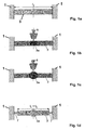
Das Prinzip eines derartigen Justierverfahrens ist in Fig. 1 dargestellt. Fig. 1a zeigt den Ausgangszustand eines zwischen zwei starren Begrenzungen 1 eingespannten Balkens 3 aus einem geeigneten Material. Der Balken 3 weist bei der Ausgangstemperatur, beispielsweise der Raumtemperatur (20° C), die Länge l0 auf. Der mittlere Bereich 3a des Balkens 3 wird mittels eines Laserstrahls 5 in kurzer Zeit erhitzt.The principle of such an adjustment method is shown in FIG. Fig. 1a shows the initial state of a clamped between two
Hierdurch entstehen zunächst im Balken 3 Druckspannungen σ(-), da die thermische Längenausdehnung des Balkens 3 durch die starren Begrenzungen 1 blockiert ist. In dieser Phase wird üblicherweise auch eine negative Dehnung ε definiert, die den im Balken 3 ausgebildeten Druckspannungen entspricht. Diese Phase des Justierverfahrens ist in Fig. 1b dargestellt.As a result, 3 compressive stresses σ (-) arise first in the beam, since the thermal expansion of the
Überschreiten die Druckspannungen σ(-) die temperaturabhängige Fließgrenze σF so kommt es zu einer plastischen Verformung des Balkens 3 im Bereich 3a. Entsprechend werden hierbei die Druckspannungen im Balken 3 reduziert. Diese Situation ist in Fig. 1c dargestellt.If the compressive stresses σ (-) exceed the temperature-dependent yield stress σ F , plastic deformation of the
Nach dem Abschalten des Laserstrahls 5 beginnt der Bereich 3a des Balkens 3 abzukühlen, wodurch ein thermisches Schrumpfen des Balkens 3 verursacht wird. Hierdurch entstehen im Balken 3 Zugspannungen σ(+) , die in der Praxis häufig in der Nähe der temperaturabhängigen Fließgrenze σF(T) liegen. Diese Situation ist in Fig. 1d symbolisch dargestellt, indem in Längsrichtung des Balkens 3 gesehen, dessen Enden über federnde Elemente 7 mit den starren Begrenzungen 1 verbunden ist. Die den Zugspannungen σ(+) entsprechenden Federkräfte bewirken bei einem praktisch realisierten Aktor eine definierte Verformung des Aktors. Hierzu ist in Fig. id nochmals verdeutlicht, dass die Zugspannungen σ(+) durch das Verkürzen des Balkens 3 infolge der während des Erhitzens verursachten plastischen Verformung im Bereich 3a entstehen, wobei die Länge des Balkens l1 nach dem Justiervorgang bei der Ausgangstemperatur kleiner ist als die ursprüngliche Länge l0 bei der Ausgangstemperatur.After switching off the laser beam 5, the
Ein Problem bei den bisher bekannten Justierverfahren besteht darin, dass, wie bereits vorstehend erwähnt, die im Balken 3 eingefrorenen Zugspannungen relativ nahe an der Fließgrenze σF liegen. Gleiches kann auch für die Druckspannungen gelten, die in denjenigen Bereichen auftreten, die die thermische Expansion bzw. das thermische Schrumpfen des Balkens blockieren. Da mikromechanische oder optische Komponenten bzw. Baugruppen in der Praxis immer für einen bestimmten Temperaturbereich, beispielsweise einen Bereich von -40° C bis +80° C, spezifiziert sind, und innerhalb des spezifizierten Bereichs vorbestimmte Anforderungen an die Genauigkeit und Langzeitstabilität erfüllen müssen, kommt es bei bisher bekannten Justierverfahren dann zu einer Dejustage des Aktors, wenn die justierten Komponenten bzw. die Baugruppe auf eine Temperatur in der oberen Region des spezifizierten Bereichs gebracht werden und die ursprüngliche Justage bei einer wesentlich niedrigeren Temperatur, beispielsweise Raumtemperatur durchgeführt wurde. Dieser Effekt wird durch die Temperaturabhängigkeit der Fließgrenze σF verursacht, wobei die meisten Materialien, die zur Herstellung von Aktoren für Laserjustierverfahren geeignet sind, eine mit steigender Temperatur fallende Fließgrenze aufweisen. Wird eine Temperatur erreicht, bei der die Fließgrenze σF den Wert der eingefrorenen Zugspannungen unterschreitet, so kommt es zu einem Fließen des Materials und zu einem Abbau der Zugspannungen auf den Wert der Fließgrenze σF bei der betreffenden Temperatur. Hiermit verbunden ist selbstverständlich eine entsprechende Dejustage des Aktors, die zumindest für hochgenau zu justierende Komponenten, die über einen großen Temperaturbereich spezifiziert werden müssen, nicht akzeptabel ist.A problem in the previously known adjustment method is that, as already mentioned above, the tensile stresses frozen in the
Der Erfindung liegt daher die Aufgabe zugrunde, ein Justierverfahren, insbesondere für das Justieren optischer oder faseroptischer Komponenten, zu schaffen, mit dem eine verbesserte Langzeitstabilität eines justierten Aktors bzw. einer Baugruppe mit einem derartigen Aktor innerhalb eines vorbestimmten Temperaturbereichs gewährleistet werden kann, wobei das Verfahren mit geringen zeitlichem und finanziellem Aufwand durchführbar ist. Des Weiteren liegt der Erfindung die Aufgabe zugrunde, einen speziellen Aktor zur einfachen Durchführung des Verfahrens zu schaffen.The invention is therefore based on the object to provide an adjustment method, in particular for the adjustment of optical or fiber-optic components, with the improved long-term stability of an adjusted actuator or an assembly can be ensured with such an actuator within a predetermined temperature range, the method with little time and financial effort is feasible. Furthermore, the invention has for its object to provide a special actuator for easy implementation of the method.
Die Erfindung löst diese Aufgabe mit den Merkmalen des Patentanspruchs 1.The invention solves this problem with the features of
Die Erfindung geht von der Erkenntnis aus, dass das Justieren eines Aktors in vorteilhafter Weise bei einer hinsichtlich des vorbestimmten Einsatztemperaturbereichs des Aktors kritischen Temperatur Tk durchgeführt werden kann. Unter einer kritischen Temperatur Tk wird in diesem Zusammenhang eine Temperatur verstanden, bei der die Fließgrenze einen solchen Wert aufweist, dass beim Durchfahren des gesamten Einsatztemperaturbereichs nur so geringe Dejustagen des justierten Aktors auftreten können, die innerhalb vorgegebener Toleranzen liegen. Bei üblichen Aktormaterialien, welche innerhalb eines Spezifikationsbereichs eine mit steigender Temperatur fallende Fließgrenze aufweisen, wird man die kritische Temperatur im oberen Bereich des Spezifikationsbereichs oder sogar eine über dessen Obergrenze To liegende Temperatur wählen.The invention is based on the recognition that the adjustment of an actuator can advantageously be carried out at a critical temperature T k with respect to the predetermined operating temperature range of the actuator. Under a critical Temperature T k is understood in this context as a temperature at which the yield point has such a value that when passing through the entire operating temperature range only so small misalignment of the adjusted actuator can occur, which are within predetermined tolerances. In the case of customary actuator materials which have a yield value falling with increasing temperature within a specification range, one will select the critical temperature in the upper range of the specification range or even a temperature above its upper limit T o .
Nach der Erfindung wird als kritische Temperatur Tk im Wesentlichen diejenige Temperatur innerhalb des Einsatztemperaturbereichs gewählt, bei der innerhalb des Einsatztemperaturbereichs die minimale Fließgrenze σF des Materials gegeben ist. In diesem Fall ist gewährleistet, dass innerhalb des Einsatztemperaturbereichs kein Fließen des Materials in denjenigen Bereichen des Aktors auftritt, in denen in Folge des Justagevorgangs Eigenspannungen auftreten.According to the invention, the critical temperature T k chosen is essentially that temperature within the operating temperature range at which the minimum yield point σ F of the material is given within the operating temperature range. In this case, it is ensured that within the operating temperature range no flow of the material occurs in those areas of the actuator in which residual stresses occur as a result of the adjustment process.
Die vorstehend erläuterte Möglichkeit der Auswahl einer noch höheren Temperatur wird in der Praxis dadurch beschränkt, dass in Baugruppen oftmals auch solche Bauelemente enthalten sind, die als maximale Temperatur der oberen Temperatur To des Einsatztemperaturbereichs ausgesetzt werden dürfen.The above-explained possibility of selecting an even higher temperature is limited in practice by the fact that in assemblies often such components are included, which may be exposed as the maximum temperature of the upper temperature T o of the operating temperature range.
Nach einer Ausführungsform des Verfahrens kann eine gesamte, den Aktor umfassende Baugruppe während des Justiervorgangs auf die kritische Temperatur Tk gebracht werden. Werden lediglich Teilbereiche des Aktors während des Justiervorgangs auf die kritische Temperatur Tk gebracht, so müssen zumindest diejenigen Bereiche umfasst sein, die der thermischen Schrumpfung unterliegen, aber auch diejenigen, die diese Schrumpfung behindern.According to one embodiment of the method, an entire assembly comprising the actuator can be brought to the critical temperature T k during the adjustment process. If only partial regions of the actuator are brought to the critical temperature T k during the adjustment process, at least those regions which are subject to thermal shrinkage must be included, but also those which hinder this shrinkage.
Ein spezieller Aktor, mit dem das erfindungsgemäße Verfahren auf besonders einfache Weise realisiert werden kann, ist so ausgebildet, dass zumindest die wesentlichen Bereiche des Aktors aus einem Material bestehen, dessen Fließgrenze σF innerhalb des gesamten Einsatztemperaturbereichs im wesentlichen bei Raumtemperatur einen minimalen Wert annimmt. Mit einem derartigen Aktor kann ein Justiervorgang, wie üblich, bei Raumtemperatur durchgeführt werden.A special actuator, with which the method according to the invention can be realized in a particularly simple manner, is designed such that at least the essential regions of the actuator consist of a material whose yield point σ F assumes a minimum value substantially at room temperature within the entire operating temperature range. With such an actuator, an adjustment process, as usual, be carried out at room temperature.
In einem Vergleichbeispiel kann der Aktor bzw. können die wesentlichen Bereiche des Aktors aus einem Material bestehen, dessen Fließgrenze im gesamten Einsatztemperaturbereich nicht abfällt bzw. im Wesentlichen konstant bleibt. Beispielsweise kann TiV13Cr11A13 als Werkstoff für den Aktor bzw. die wesentlichen Bereiche eines Aktors eingesetzt werden. Die 0,2 % Dehngrenze, Zugfestigkeit und Fließgrenze dieses Werkstoffs fällt bis zu einer Temperatur von 100 °C nicht messbar ab.In a comparison example, the actuator or the essential regions of the actuator may be made of a material whose yield strength does not drop or remain substantially constant over the entire operating temperature range. For example, TiV13Cr11A13 can be used as a material for the actuator or the essential areas of an actuator. The 0.2% yield strength, tensile strength and yield strength of this material does not drop measurably up to a temperature of 100 ° C.
Weitere Ausführungsformen der Erfindung ergeben sich aus den Unteransprüchen.Further embodiments of the invention will become apparent from the dependent claims.
Die Erfindung wird im Folgenden anhand der in der Zeichnung enthaltenen Figuren näher erläutert. Im Einzelnen zeigen
- Fig. 1
- schematische Darstellungen des Laserstrahl-Justierverfahrens;
- Fig. 2
- eine Ausführungsform eines praktischen Aktors mit zwei Doppelbrücken und
- Fig. 3
- ein Diagramm mit der temperaturabhängigen Fließgrenze σF(T) bei einem üblichen Aktormaterial innerhalb eines Einsatztemperaturbereichs [Tu;To].
- Fig. 1
- schematic illustrations of the laser beam adjustment method;
- Fig. 2
- an embodiment of a practical actuator with two double bridges and
- Fig. 3
- a diagram with the temperature-dependent yield point σ F (T) in a conventional actuator material within a service temperature range [T u ; T o ].
Das eingangs prinzipiell erläuterte Laserstrahl-Justierverfahren wird im Folgenden nochmals kurz anhand eines praktischen, in Fig. 2 dargestellten Aktors 10 näher veranschaulicht. Der Aktor 10 besteht aus einem Basisbereich 12, der über zwei Doppelbrücken I, II mit einem Justierbereich 14 verbunden ist. Für das Justieren wird jeweils eine der beiden Brücken der Doppelbrücken I, II, vorzugsweise mittig (bezogen auf die Längsachse einer Brücke), mit einem hochenergetischen Laserstrahl bestrahlt. Wird beispielsweise die in Fig. 2 links dargestellte Brücke der Doppelbrücke I in ihrem mittleren Bereich mittels des Laserstrahls erhitzt, so versucht sich die betreffende Brücke auszudehnen, wobei die thermische Ausdehnung durch die rechte Brücke der Doppelbrücke I im Wesentlichen blockiert wird. Hierdurch wird die linke Doppelbrücke in ihrem mittleren Bereich gestaucht. Während des Abkühlens versucht sich die linke Brücke der Doppelbrücke I zusammen zu ziehen, wodurch in ihr entsprechende Zugspannungen entstehen, da auch diese Bewegung weitgehend durch die rechte Brücke blockiert wird. Wird in einem nächsten Schritt auch der mittlere Bereich der in Fig. 2 rechts dargestellten Brücke der Doppelbrücke I mit dem Laser bestrahlt, so wird dieser Bereich infolge der in der linken Brücke vorhandenen Zugspannungen und der in der rechten Brücke vorhandenen Druckspannung (in Addition zu den Druckspannungen, die durch eine thermische Expansion der rechten Brücke verursacht werden) gestaucht. Während des Abkühlens versucht sich die rechte Brücke der Doppelbrücke I noch weiter zusammen zu ziehen, wobei diese Bewegung wiederum durch die linke Brücke blockiert wird. Demzufolge verbleiben Eigenspannungen, welche in der rechten Brücke als Zugspannungen und der linken Brücke als Druckspannungen ausgebildet sind.The laser beam adjustment method explained in principle at the outset will be briefly illustrated in more detail below with reference to a
Infolge dieses Justiervorgangs wird der Justierbereich 14 gegenüber der in Fig. 2 durchgezogen dargestellten Ausgangsstellung in Folge der Verkürzung der beiden Brücken der Doppelbrücke I leicht verkippt. Diese Situation ist in Fig. 2 gestrichelt dargestellt. Auf diese Weise könnte eine Justierung des Winkels einer auf dem Justierbereich 14 angeordneten Komponente (nicht dargestellt) erfolgen. Wird auch die rechte Doppelbrücke II entsprechend justiert, so kann eine hochgenaue Justierung einer auf dem Justierbereich 14 angeordneten Komponente in der Längsrichtung der Brücken erfolgen.As a result of this adjustment process, the
Werden die Justiervorgänge bei einer kritischen Temperatur Tk durchgeführt - wobei sich zumindest die zu justierende Doppelbrücke bzw. beide zu justierenden Dopelbrücken auf dieser Temperatur befinden müssen - so wird bei geeigneter Wahl der kritischen Temperatur Tk erreicht, dass nur solche Eigenspannungen in Folge des oder der Justiervorgänge eingefroren werden, die auch bei einer längerfristigen Lagerung des Aktors 10 auf einer beliebigen Temperatur innerhalb eines vorbestimmten EinsatzTemperaturbereichs [Tu;To] nur zu solchen Dejustagen führen, die innerhalb akzeptabler Toleranzen liegen.If the adjustment operations are carried out at a critical temperature T k - whereby at least the double bridge to be adjusted or both double bridges to be adjusted must be at this temperature - with a suitable choice of the critical temperature T k it is achieved that only such residual stresses as a result of or of the Adjustments are frozen, which even with a longer term storage of the
Weist beispielsweise das Aktormaterial den in Fig. 3 durchgezogen dargestellten Verlauf der temperaturabhängigen Fließgrenze σF(T) auf, so wird man, wie in Fig. 3 dargestellt, die kritische Temperatur Tk im oberen Bereich des Einsatztemperaturbereichs [Tu;To] wählen. Die kritische Temperatur Tk muss bei dem in Fig. 3 dargestellten , monoton fallenden Verkauf der Fließgrenze σF(T) so hoch gewählt werden, dass auch bei einer längerfristigen Lagerung des Aktors bei der Obergrenze Tu des Einsatztemperaturbereichs nur eine solche Dejustage in Folge eines Abbaus von Eigenspannungen in den wesentlichen Bereichen des Aktors erfolgt, die innerhalb vorgegebener zulässiger Toleranzen liegt.If, for example, the actuator material has the course of the temperature-dependent yield point σ F (T) shown in solid lines in FIG. 3, the critical temperature T k in the upper region of the operating temperature range [T u , T o ], as shown in FIG. choose. The critical temperature T k must be selected to be so high in the case of the monotonously falling sale of the yield strength σ F (T) shown in FIG. 3 that only in the case of long-term storage of the actuator at the upper limit T u of the operating temperature range would such a misalignment result a reduction of residual stresses in the essential areas of the actuator takes place, which is within predetermined permissible tolerances.
Geht man davon aus, dass in den wesentlichen Bereichen des Aktors Eigenspannungen eingefroren werden, die extrem nahe an der Fließgrenze bei der jeweils gewählten kritischen Temperatur bzw. Justage-Temperatur liegen, so kann eine Dejustage bei einer längerfristigen Lagerung des Aktors bei der Temperatur To nur dann vollständig vermieden werden, wenn die kritische Temperatur Tk gleich der oberen Bereichsgrenze To gewählt wird.If it is assumed that internal stresses are frozen in the essential areas of the actuator, which are extremely close to the yield point at the respectively selected critical temperature or adjustment temperature, then a misalignment can occur at a longer-term storage of the actuator at the temperature T o can only be avoided completely if the critical temperature T k is chosen equal to the upper range limit T o .
Wird für den Aktor bzw. dessen wesentlichen Bereiche ein Material gewählt, dessen Fließgrenze σF(T) über den gesamten Einsatztemperaturbereich [Tu;To] im wesentlichen konstant verläuft, so kann die kritische Temperatur Tk beliebig gewählt werden. Bevorzugt wird man hier die Temperatur Tk in Folge des geringsten Aufwands im Bereich der Raumtemperatur wählen.If a material whose flow limit σ F (T) is essentially constant over the entire operating temperature range [T u ; T o ] is selected for the actuator or its essential regions, then the critical temperature T k can be selected as desired. Preferably, the temperature T k will be chosen here as a result of the lowest expenditure in the region of the room temperature.
Abschließend sei erwähnt, dass das Erwärmen der wesentlichen Bereiche des Aktors, des Aktors insgesamt bzw. einer gesamten den Aktor umfassenden Baugruppe beispielsweise durch das Bestrahlen mit einer Infrarot-Strahlungsquelle, durch das Verwenden einer üblichen, beheizten Temperaturkammer oder eines beheizten Halters oder auch mittels eines Laserstrahls erfolgen kann, der entweder, entsprechend aufgeweitet, auf die wesentlichen Bereiche gerichtet ist oder der mit entsprechender Geschwindigkeit die wesentlichen Bereiche "abtastet".Finally, it should be mentioned that the heating of the essential areas of the actuator, the actuator as a whole or an entire assembly comprising the actuator, for example by irradiating with an infrared radiation source, by using a conventional, heated temperature chamber or a heated holder or by means of a laser beam, which is either, appropriately expanded, directed to the essential areas or the corresponding areas with the appropriate speed " scans ".
Claims (3)
- Adjusting process, in particular for adjusting optical or fibre-optic components,a) in which a part region (I) of an actuator (10) is heated locally in a well defined manner so that as a result of the thermal expansion of the heated part region obstructed by at least one further part region (I) of the actuator, compressive stresses are produced in the heated part region and lead to plastic compression of the heated part region when reaching the flow limit σF of the material of the part region andb) in which the heated part region is shortened during cooling and hence after cooling, a defined geometrical change in the actuator occurs, wherein as a result of an obstruction to shortening by the at least one further part region in the previously heated part region, tensile stresses are produced and compressive stresses are frozen in the at least one further region, characterised in thatc) important regions (I) of the actuator (10), in which tensile or compressive stresses are frozen after cooling, are brought to a temperature which is critical with respect to the use temperature range of the actuator during the adjusting process at least until flow processes of the material are completed at the critical temperature andd) wherein essentially that temperature within the use temperature range is selected as the critical temperature, at which the minimum flow limit σF of the material is given within the use temperature range,e) in which an actuator is used, in which the important regions consist of a material, the flow limit σF of which drops monotonously at least within the use temperature range with increasing temperature and in that essentially the temperature corresponding to the upper limit of the use temperature range is selected as the critical temperature.
- Process according to one of claims 1, characterised in that an overall component comprising the actuator is brought to the critical temperature during the adjusting process.
- Process according to one of claims 1 to 2, characterised in that heating is effected by means of a laser (5), preferably an Nd: YAG laser or diode laser.
Applications Claiming Priority (3)
| Application Number | Priority Date | Filing Date | Title |
|---|---|---|---|
| DE10118451 | 2001-04-12 | ||
| DE10118451A DE10118451A1 (en) | 2001-04-12 | 2001-04-12 | Method for precisely aligning optical or fiber-optic components using high energy laser heating of bridge elements between actuator base and alignment regions |
| PCT/DE2002/001379 WO2002084357A1 (en) | 2001-04-12 | 2002-04-12 | Adjustment method, especially a laser adjustment method, and corresponding actuator |
Publications (2)
| Publication Number | Publication Date |
|---|---|
| EP1379902A1 EP1379902A1 (en) | 2004-01-14 |
| EP1379902B1 true EP1379902B1 (en) | 2006-03-22 |
Family
ID=7681479
Family Applications (1)
| Application Number | Title | Priority Date | Filing Date |
|---|---|---|---|
| EP02740258A Expired - Lifetime EP1379902B1 (en) | 2001-04-12 | 2002-04-12 | Adjustment method, especially a laser adjustment method, and corresponding actuator |
Country Status (5)
| Country | Link |
|---|---|
| US (1) | US7862319B2 (en) |
| EP (1) | EP1379902B1 (en) |
| AT (1) | ATE321281T1 (en) |
| DE (2) | DE10118451A1 (en) |
| WO (1) | WO2002084357A1 (en) |
Families Citing this family (1)
| Publication number | Priority date | Publication date | Assignee | Title |
|---|---|---|---|---|
| EP1393418B1 (en) * | 2001-04-12 | 2005-06-22 | Finisar Corporation | Method and device for regulating the centre wavelength of a laser, especially a semiconductor laser |
Family Cites Families (27)
| Publication number | Priority date | Publication date | Assignee | Title |
|---|---|---|---|---|
| DE202143C (en) | ||||
| DE6941543U (en) | 1969-10-25 | 1970-07-09 | Siemens Ag | ELIMINATION ARRANGEMENT FOR ELECTRONIC SYSTEMS |
| DE2918100A1 (en) | 1979-05-04 | 1980-11-13 | Siemens Ag | Automatic contactless adjustment of precision contact springs - uses regulated distortion by heating with controlled energy laser beam |
| JPS5713301A (en) | 1980-06-30 | 1982-01-23 | Pentel Kk | Minutely displaceable table device |
| JPS57198415A (en) | 1981-05-30 | 1982-12-06 | Sumitomo Electric Ind Ltd | Adjusting method for optical axis of laser working equipment |
| JPS5987635A (en) | 1982-11-11 | 1984-05-21 | Sharp Corp | Optical storage element |
| PL155358B1 (en) | 1987-11-26 | 1991-11-29 | Polska Akademia Nauk Instytut Podstawowych Problemow Techniki | Method of bending metal workpieces |
| US5033052A (en) * | 1988-03-22 | 1991-07-16 | Fujitsu Limited | Optical semiconductor device and production method thereof |
| KR920010947B1 (en) * | 1989-05-24 | 1992-12-24 | 가부시끼가이샤 히다찌세이사꾸쇼 | Semiconductor light emitting device its component and lens position adjusting method |
| US5341256A (en) | 1990-11-27 | 1994-08-23 | Matsushita Electric Industrial Co., Ltd. | Rotary head adjuster |
| US5537276A (en) * | 1991-04-09 | 1996-07-16 | Matsushita Electric Industrial Co., Ltd. | Magnetic head installed on a rotary drum and method for adjusting the head height |
| JP2615525B2 (en) * | 1992-04-15 | 1997-05-28 | 松下電器産業株式会社 | How to adjust the height of the magnetic head |
| BE1007436A3 (en) | 1993-08-11 | 1995-06-13 | Philips Electronics Nv | PROCEDURE FOR MOVING AT LEAST TWO PARTS OF AN ACTUATOR AND AN ACTUATOR SUITABLE FOR USE IN SUCH A PROCEDURE. |
| US5870417A (en) * | 1996-12-20 | 1999-02-09 | Sdl, Inc. | Thermal compensators for waveguide DBR laser sources |
| DE19704502C1 (en) | 1997-02-06 | 1998-02-26 | Siemens Ag | Laser module with fine adjustment method e.g. for micrometre range transmission engineering |
| US5914972A (en) * | 1997-03-24 | 1999-06-22 | Sdl, Inc. | Thermal compensators for waveguide DBR laser sources |
| DE19752028C2 (en) | 1997-11-24 | 1999-09-30 | Siemens Ag | Method for adjusting the valve needle stroke in metering valves and metering valve with valve needle stroke adjusted according to this method |
| DE19805849A1 (en) | 1998-02-13 | 1999-09-02 | Daimler Chrysler Ag | Method for building and connecting optical components, in particular optical components in a laser resonator, and laser resonator used in this method |
| US6154952A (en) * | 1998-04-22 | 2000-12-05 | Hutchinson Technology, Inc. | Attachment isolation structures for adjusting head slider static attitude |
| US6092914A (en) * | 1998-06-22 | 2000-07-25 | Electronics Theatre Controls | Zoom lighting fixture having multifunction actuator |
| JP2000357309A (en) | 1999-06-14 | 2000-12-26 | Sony Corp | Device and method for adjusting position of magnetic head |
| US6559464B1 (en) | 1999-11-15 | 2003-05-06 | Axsun Technologies, Inc. | Optical system active alignment process including alignment structure attach, position search, and deformation |
| JP2003517254A (en) * | 1999-12-17 | 2003-05-20 | コーニンクレッカ フィリップス エレクトロニクス エヌ ヴィ | Positioning method using actuator having three bridges |
| DE10037975C1 (en) | 2000-08-03 | 2002-02-21 | Infineon Technologies Ag | Adjustment device and method for its adjustment |
| DE10112274B4 (en) * | 2001-03-14 | 2006-05-24 | Finisar Corp.(N.D.Ges.D.Staates Delaware), Sunnyvale | Optoelectronic transmission module and method for its production |
| EP1393418B1 (en) | 2001-04-12 | 2005-06-22 | Finisar Corporation | Method and device for regulating the centre wavelength of a laser, especially a semiconductor laser |
| DE10128827A1 (en) | 2001-06-15 | 2003-01-09 | Aifotec Ag Fiberoptics | Adjustment method, in particular laser adjustment method and actuator suitable for this |
-
2001
- 2001-04-12 DE DE10118451A patent/DE10118451A1/en not_active Withdrawn
-
2002
- 2002-04-12 US US10/473,940 patent/US7862319B2/en active Active
- 2002-04-12 WO PCT/DE2002/001379 patent/WO2002084357A1/en not_active Application Discontinuation
- 2002-04-12 AT AT02740258T patent/ATE321281T1/en not_active IP Right Cessation
- 2002-04-12 EP EP02740258A patent/EP1379902B1/en not_active Expired - Lifetime
- 2002-04-12 DE DE50206144T patent/DE50206144D1/en not_active Expired - Fee Related
Also Published As
| Publication number | Publication date |
|---|---|
| US7862319B2 (en) | 2011-01-04 |
| ATE321281T1 (en) | 2006-04-15 |
| WO2002084357A1 (en) | 2002-10-24 |
| EP1379902A1 (en) | 2004-01-14 |
| US20080315443A1 (en) | 2008-12-25 |
| DE50206144D1 (en) | 2006-05-11 |
| DE10118451A1 (en) | 2002-10-24 |
Similar Documents
| Publication | Publication Date | Title |
|---|---|---|
| DE102010003750A1 (en) | Method and arrangement for changing the beam profile characteristic of a laser beam by means of a multiple-clad fiber | |
| WO2020016362A1 (en) | Optical assembly for variably generating a multi-focus profile | |
| DE3142630A1 (en) | OPTICAL SYSTEM FOR GENERATING A COLLIMATED BUNCH OF LIGHT | |
| EP0679920A1 (en) | Resilient hinge | |
| EP0527397B1 (en) | Device for making a bifocal contact lens | |
| EP2473313B1 (en) | Method for welding parts with spot contact or short line contact in the joining region and joining device | |
| WO2010145803A1 (en) | Kinematic mount | |
| DE102013223017A1 (en) | Optical module | |
| EP1379902B1 (en) | Adjustment method, especially a laser adjustment method, and corresponding actuator | |
| DE102017206461B4 (en) | Apparatus and method for laser-based separation of a transparent, brittle-breaking workpiece | |
| EP1053576B1 (en) | Method for constructing and connecting optical components, especially optical components in a laser resonator, and a laser resonator | |
| EP1395859B1 (en) | Laser adjustable actuator, optical component and adjustment method | |
| DE102018216964A1 (en) | Actuator device for aligning an element, projection exposure system for semiconductor lithography and method for aligning an element | |
| EP1437173A1 (en) | Static mixer for highly viscous media | |
| DE102013021151B3 (en) | Method and arrangement for passive compensation of thermal lenses in optical systems | |
| DE10303549B3 (en) | Optical device with tubular housing, e.g. for telescopes or microscopes, has controlled deformation devices that cause controlled increases or reductions in wall diameter integrated into wall | |
| WO1999054970A2 (en) | Resonator array for solid-state lasers | |
| DE4017411C2 (en) | ||
| DE4232326A1 (en) | Coupling arrangement for coupling an optical fiber to an optoelectronic module | |
| WO2001053692A2 (en) | Device and method for generating a system pressure in an injection unit | |
| DE20315196U1 (en) | Laser-adjustable holder for optical components in laser device, has tube-shaped adjustment element with multiple double-bridge actuators for changing position of adjustment plane at front of tube | |
| WO2020177986A1 (en) | Method for aligning at least two components, and component assembly | |
| DE102018126791A1 (en) | Light guide arrangement, method for its repair, use of a hollow cylindrical capillary section and attachment element kit | |
| WO2020157279A1 (en) | Optical system and method for beam formation | |
| EP1225127A1 (en) | Support structure having alternative states of high strength or low thermal conductivity, and connecting strut |
Legal Events
| Date | Code | Title | Description |
|---|---|---|---|
| PUAI | Public reference made under article 153(3) epc to a published international application that has entered the european phase |
Free format text: ORIGINAL CODE: 0009012 |
|
| 17P | Request for examination filed |
Effective date: 20031106 |
|
| AK | Designated contracting states |
Kind code of ref document: A1 Designated state(s): AT BE CH CY DE DK ES FI FR GB GR IE IT LI LU MC NL PT SE TR |
|
| AX | Request for extension of the european patent |
Extension state: AL LT LV MK RO SI |
|
| 17Q | First examination report despatched |
Effective date: 20041018 |
|
| GRAP | Despatch of communication of intention to grant a patent |
Free format text: ORIGINAL CODE: EPIDOSNIGR1 |
|
| GRAS | Grant fee paid |
Free format text: ORIGINAL CODE: EPIDOSNIGR3 |
|
| GRAA | (expected) grant |
Free format text: ORIGINAL CODE: 0009210 |
|
| AK | Designated contracting states |
Kind code of ref document: B1 Designated state(s): AT BE CH CY DE DK ES FI FR GB GR IE IT LI LU MC NL PT SE TR |
|
| AX | Request for extension of the european patent |
Extension state: AL LT LV MK RO SI |
|
| PG25 | Lapsed in a contracting state [announced via postgrant information from national office to epo] |
Ref country code: IT Free format text: LAPSE BECAUSE OF FAILURE TO SUBMIT A TRANSLATION OF THE DESCRIPTION OR TO PAY THE FEE WITHIN THE PRESCRIBED TIME-LIMIT;WARNING: LAPSES OF ITALIAN PATENTS WITH EFFECTIVE DATE BEFORE 2007 MAY HAVE OCCURRED AT ANY TIME BEFORE 2007. THE CORRECT EFFECTIVE DATE MAY BE DIFFERENT FROM THE ONE RECORDED. Effective date: 20060322 Ref country code: IE Free format text: LAPSE BECAUSE OF FAILURE TO SUBMIT A TRANSLATION OF THE DESCRIPTION OR TO PAY THE FEE WITHIN THE PRESCRIBED TIME-LIMIT Effective date: 20060322 Ref country code: GB Free format text: LAPSE BECAUSE OF FAILURE TO SUBMIT A TRANSLATION OF THE DESCRIPTION OR TO PAY THE FEE WITHIN THE PRESCRIBED TIME-LIMIT Effective date: 20060322 Ref country code: NL Free format text: LAPSE BECAUSE OF FAILURE TO SUBMIT A TRANSLATION OF THE DESCRIPTION OR TO PAY THE FEE WITHIN THE PRESCRIBED TIME-LIMIT Effective date: 20060322 |
|
| REG | Reference to a national code |
Ref country code: GB Ref legal event code: FG4D Free format text: NOT ENGLISH |
|
| REG | Reference to a national code |
Ref country code: CH Ref legal event code: EP |
|
| PG25 | Lapsed in a contracting state [announced via postgrant information from national office to epo] |
Ref country code: AT Free format text: LAPSE BECAUSE OF NON-PAYMENT OF DUE FEES Effective date: 20060412 |
|
| REG | Reference to a national code |
Ref country code: IE Ref legal event code: FG4D Free format text: LANGUAGE OF EP DOCUMENT: GERMAN |
|
| PG25 | Lapsed in a contracting state [announced via postgrant information from national office to epo] |
Ref country code: LI Free format text: LAPSE BECAUSE OF NON-PAYMENT OF DUE FEES Effective date: 20060430 Ref country code: BE Free format text: LAPSE BECAUSE OF NON-PAYMENT OF DUE FEES Effective date: 20060430 Ref country code: CH Free format text: LAPSE BECAUSE OF NON-PAYMENT OF DUE FEES Effective date: 20060430 Ref country code: MC Free format text: LAPSE BECAUSE OF NON-PAYMENT OF DUE FEES Effective date: 20060430 |
|
| REF | Corresponds to: |
Ref document number: 50206144 Country of ref document: DE Date of ref document: 20060511 Kind code of ref document: P |
|
| PG25 | Lapsed in a contracting state [announced via postgrant information from national office to epo] |
Ref country code: SE Free format text: LAPSE BECAUSE OF FAILURE TO SUBMIT A TRANSLATION OF THE DESCRIPTION OR TO PAY THE FEE WITHIN THE PRESCRIBED TIME-LIMIT Effective date: 20060622 Ref country code: DK Free format text: LAPSE BECAUSE OF FAILURE TO SUBMIT A TRANSLATION OF THE DESCRIPTION OR TO PAY THE FEE WITHIN THE PRESCRIBED TIME-LIMIT Effective date: 20060622 |
|
| PG25 | Lapsed in a contracting state [announced via postgrant information from national office to epo] |
Ref country code: ES Free format text: LAPSE BECAUSE OF FAILURE TO SUBMIT A TRANSLATION OF THE DESCRIPTION OR TO PAY THE FEE WITHIN THE PRESCRIBED TIME-LIMIT Effective date: 20060703 |
|
| PG25 | Lapsed in a contracting state [announced via postgrant information from national office to epo] |
Ref country code: PT Free format text: LAPSE BECAUSE OF FAILURE TO SUBMIT A TRANSLATION OF THE DESCRIPTION OR TO PAY THE FEE WITHIN THE PRESCRIBED TIME-LIMIT Effective date: 20060822 |
|
| LTIE | Lt: invalidation of european patent or patent extension |
Effective date: 20060322 |
|
| NLV1 | Nl: lapsed or annulled due to failure to fulfill the requirements of art. 29p and 29m of the patents act | ||
| GBV | Gb: ep patent (uk) treated as always having been void in accordance with gb section 77(7)/1977 [no translation filed] |
Effective date: 20060322 |
|
| PG25 | Lapsed in a contracting state [announced via postgrant information from national office to epo] |
Ref country code: DE Free format text: LAPSE BECAUSE OF NON-PAYMENT OF DUE FEES Effective date: 20061101 |
|
| REG | Reference to a national code |
Ref country code: IE Ref legal event code: FD4D |
|
| REG | Reference to a national code |
Ref country code: CH Ref legal event code: PL |
|
| PLBE | No opposition filed within time limit |
Free format text: ORIGINAL CODE: 0009261 |
|
| STAA | Information on the status of an ep patent application or granted ep patent |
Free format text: STATUS: NO OPPOSITION FILED WITHIN TIME LIMIT |
|
| 26N | No opposition filed |
Effective date: 20061227 |
|
| EN | Fr: translation not filed | ||
| BERE | Be: lapsed |
Owner name: FINISAR CORP. Effective date: 20060430 |
|
| PG25 | Lapsed in a contracting state [announced via postgrant information from national office to epo] |
Ref country code: GR Free format text: LAPSE BECAUSE OF FAILURE TO SUBMIT A TRANSLATION OF THE DESCRIPTION OR TO PAY THE FEE WITHIN THE PRESCRIBED TIME-LIMIT Effective date: 20060623 Ref country code: FR Free format text: LAPSE BECAUSE OF FAILURE TO SUBMIT A TRANSLATION OF THE DESCRIPTION OR TO PAY THE FEE WITHIN THE PRESCRIBED TIME-LIMIT Effective date: 20070309 |
|
| PG25 | Lapsed in a contracting state [announced via postgrant information from national office to epo] |
Ref country code: FI Free format text: LAPSE BECAUSE OF FAILURE TO SUBMIT A TRANSLATION OF THE DESCRIPTION OR TO PAY THE FEE WITHIN THE PRESCRIBED TIME-LIMIT Effective date: 20060322 |
|
| PG25 | Lapsed in a contracting state [announced via postgrant information from national office to epo] |
Ref country code: LU Free format text: LAPSE BECAUSE OF NON-PAYMENT OF DUE FEES Effective date: 20060412 Ref country code: TR Free format text: LAPSE BECAUSE OF FAILURE TO SUBMIT A TRANSLATION OF THE DESCRIPTION OR TO PAY THE FEE WITHIN THE PRESCRIBED TIME-LIMIT Effective date: 20060322 |
|
| PG25 | Lapsed in a contracting state [announced via postgrant information from national office to epo] |
Ref country code: FR Free format text: LAPSE BECAUSE OF FAILURE TO SUBMIT A TRANSLATION OF THE DESCRIPTION OR TO PAY THE FEE WITHIN THE PRESCRIBED TIME-LIMIT Effective date: 20060430 |
|
| PG25 | Lapsed in a contracting state [announced via postgrant information from national office to epo] |
Ref country code: FR Free format text: LAPSE BECAUSE OF FAILURE TO SUBMIT A TRANSLATION OF THE DESCRIPTION OR TO PAY THE FEE WITHIN THE PRESCRIBED TIME-LIMIT Effective date: 20060322 Ref country code: CY Free format text: LAPSE BECAUSE OF FAILURE TO SUBMIT A TRANSLATION OF THE DESCRIPTION OR TO PAY THE FEE WITHIN THE PRESCRIBED TIME-LIMIT Effective date: 20060322 |