EP1379200B1 - Adjustable mount assembly for an object - Google Patents
Adjustable mount assembly for an object Download PDFInfo
- Publication number
- EP1379200B1 EP1379200B1 EP02705796A EP02705796A EP1379200B1 EP 1379200 B1 EP1379200 B1 EP 1379200B1 EP 02705796 A EP02705796 A EP 02705796A EP 02705796 A EP02705796 A EP 02705796A EP 1379200 B1 EP1379200 B1 EP 1379200B1
- Authority
- EP
- European Patent Office
- Prior art keywords
- pivot
- mounting
- mounting hub
- pivot pin
- hub
- Prior art date
- Legal status (The legal status is an assumption and is not a legal conclusion. Google has not performed a legal analysis and makes no representation as to the accuracy of the status listed.)
- Expired - Lifetime
Links
- 210000004095 humeral head Anatomy 0.000 claims abstract description 5
- 230000013011 mating Effects 0.000 claims description 6
- 238000000034 method Methods 0.000 abstract description 12
- 210000002758 humerus Anatomy 0.000 description 34
- 230000000295 complement effect Effects 0.000 description 8
- 238000013519 translation Methods 0.000 description 8
- 239000004033 plastic Substances 0.000 description 7
- 239000002184 metal Substances 0.000 description 6
- 241001653121 Glenoides Species 0.000 description 5
- 210000000988 bone and bone Anatomy 0.000 description 5
- 238000003754 machining Methods 0.000 description 5
- 238000000465 moulding Methods 0.000 description 5
- 210000002435 tendon Anatomy 0.000 description 5
- 230000006835 compression Effects 0.000 description 4
- 238000007906 compression Methods 0.000 description 4
- 230000006378 damage Effects 0.000 description 4
- 239000003550 marker Substances 0.000 description 4
- 230000009471 action Effects 0.000 description 3
- 238000007796 conventional method Methods 0.000 description 3
- 238000002513 implantation Methods 0.000 description 3
- 230000007246 mechanism Effects 0.000 description 3
- 210000001991 scapula Anatomy 0.000 description 3
- 208000027418 Wounds and injury Diseases 0.000 description 2
- 201000010099 disease Diseases 0.000 description 2
- 208000037265 diseases, disorders, signs and symptoms Diseases 0.000 description 2
- 208000014674 injury Diseases 0.000 description 2
- 238000003780 insertion Methods 0.000 description 2
- 230000037431 insertion Effects 0.000 description 2
- 239000000463 material Substances 0.000 description 2
- 210000000323 shoulder joint Anatomy 0.000 description 2
- 238000001356 surgical procedure Methods 0.000 description 2
- 230000015572 biosynthetic process Effects 0.000 description 1
- 229910010293 ceramic material Inorganic materials 0.000 description 1
- 238000010276 construction Methods 0.000 description 1
- 230000008878 coupling Effects 0.000 description 1
- 238000010168 coupling process Methods 0.000 description 1
- 238000005859 coupling reaction Methods 0.000 description 1
- 230000007423 decrease Effects 0.000 description 1
- 230000006866 deterioration Effects 0.000 description 1
- 238000011156 evaluation Methods 0.000 description 1
- 230000003278 mimic effect Effects 0.000 description 1
- 238000012986 modification Methods 0.000 description 1
- 230000004048 modification Effects 0.000 description 1
- 230000009467 reduction Effects 0.000 description 1
- 230000000284 resting effect Effects 0.000 description 1
- 229910001220 stainless steel Inorganic materials 0.000 description 1
- 239000010935 stainless steel Substances 0.000 description 1
- 238000012800 visualization Methods 0.000 description 1
Images
















Classifications
-
- A—HUMAN NECESSITIES
- A61—MEDICAL OR VETERINARY SCIENCE; HYGIENE
- A61F—FILTERS IMPLANTABLE INTO BLOOD VESSELS; PROSTHESES; DEVICES PROVIDING PATENCY TO, OR PREVENTING COLLAPSING OF, TUBULAR STRUCTURES OF THE BODY, e.g. STENTS; ORTHOPAEDIC, NURSING OR CONTRACEPTIVE DEVICES; FOMENTATION; TREATMENT OR PROTECTION OF EYES OR EARS; BANDAGES, DRESSINGS OR ABSORBENT PADS; FIRST-AID KITS
- A61F2/00—Filters implantable into blood vessels; Prostheses, i.e. artificial substitutes or replacements for parts of the body; Appliances for connecting them with the body; Devices providing patency to, or preventing collapsing of, tubular structures of the body, e.g. stents
- A61F2/02—Prostheses implantable into the body
- A61F2/30—Joints
- A61F2/40—Joints for shoulders
- A61F2/4014—Humeral heads or necks; Connections of endoprosthetic heads or necks to endoprosthetic humeral shafts
-
- A—HUMAN NECESSITIES
- A61—MEDICAL OR VETERINARY SCIENCE; HYGIENE
- A61F—FILTERS IMPLANTABLE INTO BLOOD VESSELS; PROSTHESES; DEVICES PROVIDING PATENCY TO, OR PREVENTING COLLAPSING OF, TUBULAR STRUCTURES OF THE BODY, e.g. STENTS; ORTHOPAEDIC, NURSING OR CONTRACEPTIVE DEVICES; FOMENTATION; TREATMENT OR PROTECTION OF EYES OR EARS; BANDAGES, DRESSINGS OR ABSORBENT PADS; FIRST-AID KITS
- A61F2/00—Filters implantable into blood vessels; Prostheses, i.e. artificial substitutes or replacements for parts of the body; Appliances for connecting them with the body; Devices providing patency to, or preventing collapsing of, tubular structures of the body, e.g. stents
- A61F2/02—Prostheses implantable into the body
- A61F2/30—Joints
- A61F2/46—Special tools for implanting artificial joints
- A61F2/4684—Trial or dummy prostheses
-
- F—MECHANICAL ENGINEERING; LIGHTING; HEATING; WEAPONS; BLASTING
- F16—ENGINEERING ELEMENTS AND UNITS; GENERAL MEASURES FOR PRODUCING AND MAINTAINING EFFECTIVE FUNCTIONING OF MACHINES OR INSTALLATIONS; THERMAL INSULATION IN GENERAL
- F16C—SHAFTS; FLEXIBLE SHAFTS; ELEMENTS OR CRANKSHAFT MECHANISMS; ROTARY BODIES OTHER THAN GEARING ELEMENTS; BEARINGS
- F16C11/00—Pivots; Pivotal connections
- F16C11/04—Pivotal connections
- F16C11/06—Ball-joints; Other joints having more than one degree of angular freedom, i.e. universal joints
- F16C11/0661—Ball-joints; Other joints having more than one degree of angular freedom, i.e. universal joints the two co-operative parts each having both convex and concave interfaces
-
- F—MECHANICAL ENGINEERING; LIGHTING; HEATING; WEAPONS; BLASTING
- F16—ENGINEERING ELEMENTS AND UNITS; GENERAL MEASURES FOR PRODUCING AND MAINTAINING EFFECTIVE FUNCTIONING OF MACHINES OR INSTALLATIONS; THERMAL INSULATION IN GENERAL
- F16C—SHAFTS; FLEXIBLE SHAFTS; ELEMENTS OR CRANKSHAFT MECHANISMS; ROTARY BODIES OTHER THAN GEARING ELEMENTS; BEARINGS
- F16C11/00—Pivots; Pivotal connections
- F16C11/04—Pivotal connections
- F16C11/10—Arrangements for locking
- F16C11/103—Arrangements for locking frictionally clamped
- F16C11/106—Arrangements for locking frictionally clamped for ball joints
-
- F—MECHANICAL ENGINEERING; LIGHTING; HEATING; WEAPONS; BLASTING
- F16—ENGINEERING ELEMENTS AND UNITS; GENERAL MEASURES FOR PRODUCING AND MAINTAINING EFFECTIVE FUNCTIONING OF MACHINES OR INSTALLATIONS; THERMAL INSULATION IN GENERAL
- F16M—FRAMES, CASINGS OR BEDS OF ENGINES, MACHINES OR APPARATUS, NOT SPECIFIC TO ENGINES, MACHINES OR APPARATUS PROVIDED FOR ELSEWHERE; STANDS; SUPPORTS
- F16M11/00—Stands or trestles as supports for apparatus or articles placed thereon ; Stands for scientific apparatus such as gravitational force meters
- F16M11/02—Heads
- F16M11/04—Means for attachment of apparatus; Means allowing adjustment of the apparatus relatively to the stand
- F16M11/06—Means for attachment of apparatus; Means allowing adjustment of the apparatus relatively to the stand allowing pivoting
- F16M11/12—Means for attachment of apparatus; Means allowing adjustment of the apparatus relatively to the stand allowing pivoting in more than one direction
- F16M11/14—Means for attachment of apparatus; Means allowing adjustment of the apparatus relatively to the stand allowing pivoting in more than one direction with ball-joint
-
- A—HUMAN NECESSITIES
- A61—MEDICAL OR VETERINARY SCIENCE; HYGIENE
- A61F—FILTERS IMPLANTABLE INTO BLOOD VESSELS; PROSTHESES; DEVICES PROVIDING PATENCY TO, OR PREVENTING COLLAPSING OF, TUBULAR STRUCTURES OF THE BODY, e.g. STENTS; ORTHOPAEDIC, NURSING OR CONTRACEPTIVE DEVICES; FOMENTATION; TREATMENT OR PROTECTION OF EYES OR EARS; BANDAGES, DRESSINGS OR ABSORBENT PADS; FIRST-AID KITS
- A61F2/00—Filters implantable into blood vessels; Prostheses, i.e. artificial substitutes or replacements for parts of the body; Appliances for connecting them with the body; Devices providing patency to, or preventing collapsing of, tubular structures of the body, e.g. stents
- A61F2/02—Prostheses implantable into the body
- A61F2/30—Joints
- A61F2/40—Joints for shoulders
-
- A—HUMAN NECESSITIES
- A61—MEDICAL OR VETERINARY SCIENCE; HYGIENE
- A61F—FILTERS IMPLANTABLE INTO BLOOD VESSELS; PROSTHESES; DEVICES PROVIDING PATENCY TO, OR PREVENTING COLLAPSING OF, TUBULAR STRUCTURES OF THE BODY, e.g. STENTS; ORTHOPAEDIC, NURSING OR CONTRACEPTIVE DEVICES; FOMENTATION; TREATMENT OR PROTECTION OF EYES OR EARS; BANDAGES, DRESSINGS OR ABSORBENT PADS; FIRST-AID KITS
- A61F2/00—Filters implantable into blood vessels; Prostheses, i.e. artificial substitutes or replacements for parts of the body; Appliances for connecting them with the body; Devices providing patency to, or preventing collapsing of, tubular structures of the body, e.g. stents
- A61F2/02—Prostheses implantable into the body
- A61F2/30—Joints
- A61F2002/30001—Additional features of subject-matter classified in A61F2/28, A61F2/30 and subgroups thereof
- A61F2002/30316—The prosthesis having different structural features at different locations within the same prosthesis; Connections between prosthetic parts; Special structural features of bone or joint prostheses not otherwise provided for
- A61F2002/30329—Connections or couplings between prosthetic parts, e.g. between modular parts; Connecting elements
- A61F2002/30331—Connections or couplings between prosthetic parts, e.g. between modular parts; Connecting elements made by longitudinally pushing a protrusion into a complementarily-shaped recess, e.g. held by friction fit
- A61F2002/30332—Conically- or frustoconically-shaped protrusion and recess
-
- A—HUMAN NECESSITIES
- A61—MEDICAL OR VETERINARY SCIENCE; HYGIENE
- A61F—FILTERS IMPLANTABLE INTO BLOOD VESSELS; PROSTHESES; DEVICES PROVIDING PATENCY TO, OR PREVENTING COLLAPSING OF, TUBULAR STRUCTURES OF THE BODY, e.g. STENTS; ORTHOPAEDIC, NURSING OR CONTRACEPTIVE DEVICES; FOMENTATION; TREATMENT OR PROTECTION OF EYES OR EARS; BANDAGES, DRESSINGS OR ABSORBENT PADS; FIRST-AID KITS
- A61F2/00—Filters implantable into blood vessels; Prostheses, i.e. artificial substitutes or replacements for parts of the body; Appliances for connecting them with the body; Devices providing patency to, or preventing collapsing of, tubular structures of the body, e.g. stents
- A61F2/02—Prostheses implantable into the body
- A61F2/30—Joints
- A61F2002/30001—Additional features of subject-matter classified in A61F2/28, A61F2/30 and subgroups thereof
- A61F2002/30316—The prosthesis having different structural features at different locations within the same prosthesis; Connections between prosthetic parts; Special structural features of bone or joint prostheses not otherwise provided for
- A61F2002/30329—Connections or couplings between prosthetic parts, e.g. between modular parts; Connecting elements
- A61F2002/30331—Connections or couplings between prosthetic parts, e.g. between modular parts; Connecting elements made by longitudinally pushing a protrusion into a complementarily-shaped recess, e.g. held by friction fit
- A61F2002/30378—Spherically-shaped protrusion and recess
-
- A—HUMAN NECESSITIES
- A61—MEDICAL OR VETERINARY SCIENCE; HYGIENE
- A61F—FILTERS IMPLANTABLE INTO BLOOD VESSELS; PROSTHESES; DEVICES PROVIDING PATENCY TO, OR PREVENTING COLLAPSING OF, TUBULAR STRUCTURES OF THE BODY, e.g. STENTS; ORTHOPAEDIC, NURSING OR CONTRACEPTIVE DEVICES; FOMENTATION; TREATMENT OR PROTECTION OF EYES OR EARS; BANDAGES, DRESSINGS OR ABSORBENT PADS; FIRST-AID KITS
- A61F2/00—Filters implantable into blood vessels; Prostheses, i.e. artificial substitutes or replacements for parts of the body; Appliances for connecting them with the body; Devices providing patency to, or preventing collapsing of, tubular structures of the body, e.g. stents
- A61F2/02—Prostheses implantable into the body
- A61F2/30—Joints
- A61F2002/30001—Additional features of subject-matter classified in A61F2/28, A61F2/30 and subgroups thereof
- A61F2002/30316—The prosthesis having different structural features at different locations within the same prosthesis; Connections between prosthetic parts; Special structural features of bone or joint prostheses not otherwise provided for
- A61F2002/30329—Connections or couplings between prosthetic parts, e.g. between modular parts; Connecting elements
- A61F2002/30405—Connections or couplings between prosthetic parts, e.g. between modular parts; Connecting elements made by screwing complementary threads machined on the parts themselves
-
- A—HUMAN NECESSITIES
- A61—MEDICAL OR VETERINARY SCIENCE; HYGIENE
- A61F—FILTERS IMPLANTABLE INTO BLOOD VESSELS; PROSTHESES; DEVICES PROVIDING PATENCY TO, OR PREVENTING COLLAPSING OF, TUBULAR STRUCTURES OF THE BODY, e.g. STENTS; ORTHOPAEDIC, NURSING OR CONTRACEPTIVE DEVICES; FOMENTATION; TREATMENT OR PROTECTION OF EYES OR EARS; BANDAGES, DRESSINGS OR ABSORBENT PADS; FIRST-AID KITS
- A61F2/00—Filters implantable into blood vessels; Prostheses, i.e. artificial substitutes or replacements for parts of the body; Appliances for connecting them with the body; Devices providing patency to, or preventing collapsing of, tubular structures of the body, e.g. stents
- A61F2/02—Prostheses implantable into the body
- A61F2/30—Joints
- A61F2002/30001—Additional features of subject-matter classified in A61F2/28, A61F2/30 and subgroups thereof
- A61F2002/30316—The prosthesis having different structural features at different locations within the same prosthesis; Connections between prosthetic parts; Special structural features of bone or joint prostheses not otherwise provided for
- A61F2002/30329—Connections or couplings between prosthetic parts, e.g. between modular parts; Connecting elements
- A61F2002/30433—Connections or couplings between prosthetic parts, e.g. between modular parts; Connecting elements using additional screws, bolts, dowels, rivets or washers e.g. connecting screws
-
- A—HUMAN NECESSITIES
- A61—MEDICAL OR VETERINARY SCIENCE; HYGIENE
- A61F—FILTERS IMPLANTABLE INTO BLOOD VESSELS; PROSTHESES; DEVICES PROVIDING PATENCY TO, OR PREVENTING COLLAPSING OF, TUBULAR STRUCTURES OF THE BODY, e.g. STENTS; ORTHOPAEDIC, NURSING OR CONTRACEPTIVE DEVICES; FOMENTATION; TREATMENT OR PROTECTION OF EYES OR EARS; BANDAGES, DRESSINGS OR ABSORBENT PADS; FIRST-AID KITS
- A61F2/00—Filters implantable into blood vessels; Prostheses, i.e. artificial substitutes or replacements for parts of the body; Appliances for connecting them with the body; Devices providing patency to, or preventing collapsing of, tubular structures of the body, e.g. stents
- A61F2/02—Prostheses implantable into the body
- A61F2/30—Joints
- A61F2002/30001—Additional features of subject-matter classified in A61F2/28, A61F2/30 and subgroups thereof
- A61F2002/30316—The prosthesis having different structural features at different locations within the same prosthesis; Connections between prosthetic parts; Special structural features of bone or joint prostheses not otherwise provided for
- A61F2002/30329—Connections or couplings between prosthetic parts, e.g. between modular parts; Connecting elements
- A61F2002/30476—Connections or couplings between prosthetic parts, e.g. between modular parts; Connecting elements locked by an additional locking mechanism
- A61F2002/30507—Connections or couplings between prosthetic parts, e.g. between modular parts; Connecting elements locked by an additional locking mechanism using a threaded locking member, e.g. a locking screw or a set screw
-
- A—HUMAN NECESSITIES
- A61—MEDICAL OR VETERINARY SCIENCE; HYGIENE
- A61F—FILTERS IMPLANTABLE INTO BLOOD VESSELS; PROSTHESES; DEVICES PROVIDING PATENCY TO, OR PREVENTING COLLAPSING OF, TUBULAR STRUCTURES OF THE BODY, e.g. STENTS; ORTHOPAEDIC, NURSING OR CONTRACEPTIVE DEVICES; FOMENTATION; TREATMENT OR PROTECTION OF EYES OR EARS; BANDAGES, DRESSINGS OR ABSORBENT PADS; FIRST-AID KITS
- A61F2/00—Filters implantable into blood vessels; Prostheses, i.e. artificial substitutes or replacements for parts of the body; Appliances for connecting them with the body; Devices providing patency to, or preventing collapsing of, tubular structures of the body, e.g. stents
- A61F2/02—Prostheses implantable into the body
- A61F2/30—Joints
- A61F2002/30001—Additional features of subject-matter classified in A61F2/28, A61F2/30 and subgroups thereof
- A61F2002/30316—The prosthesis having different structural features at different locations within the same prosthesis; Connections between prosthetic parts; Special structural features of bone or joint prostheses not otherwise provided for
- A61F2002/30329—Connections or couplings between prosthetic parts, e.g. between modular parts; Connecting elements
- A61F2002/30476—Connections or couplings between prosthetic parts, e.g. between modular parts; Connecting elements locked by an additional locking mechanism
- A61F2002/30514—Connections or couplings between prosthetic parts, e.g. between modular parts; Connecting elements locked by an additional locking mechanism using a locking washer
-
- A—HUMAN NECESSITIES
- A61—MEDICAL OR VETERINARY SCIENCE; HYGIENE
- A61F—FILTERS IMPLANTABLE INTO BLOOD VESSELS; PROSTHESES; DEVICES PROVIDING PATENCY TO, OR PREVENTING COLLAPSING OF, TUBULAR STRUCTURES OF THE BODY, e.g. STENTS; ORTHOPAEDIC, NURSING OR CONTRACEPTIVE DEVICES; FOMENTATION; TREATMENT OR PROTECTION OF EYES OR EARS; BANDAGES, DRESSINGS OR ABSORBENT PADS; FIRST-AID KITS
- A61F2/00—Filters implantable into blood vessels; Prostheses, i.e. artificial substitutes or replacements for parts of the body; Appliances for connecting them with the body; Devices providing patency to, or preventing collapsing of, tubular structures of the body, e.g. stents
- A61F2/02—Prostheses implantable into the body
- A61F2/30—Joints
- A61F2002/30001—Additional features of subject-matter classified in A61F2/28, A61F2/30 and subgroups thereof
- A61F2002/30316—The prosthesis having different structural features at different locations within the same prosthesis; Connections between prosthetic parts; Special structural features of bone or joint prostheses not otherwise provided for
- A61F2002/30535—Special structural features of bone or joint prostheses not otherwise provided for
- A61F2002/30537—Special structural features of bone or joint prostheses not otherwise provided for adjustable
- A61F2002/30538—Special structural features of bone or joint prostheses not otherwise provided for adjustable for adjusting angular orientation
-
- A—HUMAN NECESSITIES
- A61—MEDICAL OR VETERINARY SCIENCE; HYGIENE
- A61F—FILTERS IMPLANTABLE INTO BLOOD VESSELS; PROSTHESES; DEVICES PROVIDING PATENCY TO, OR PREVENTING COLLAPSING OF, TUBULAR STRUCTURES OF THE BODY, e.g. STENTS; ORTHOPAEDIC, NURSING OR CONTRACEPTIVE DEVICES; FOMENTATION; TREATMENT OR PROTECTION OF EYES OR EARS; BANDAGES, DRESSINGS OR ABSORBENT PADS; FIRST-AID KITS
- A61F2/00—Filters implantable into blood vessels; Prostheses, i.e. artificial substitutes or replacements for parts of the body; Appliances for connecting them with the body; Devices providing patency to, or preventing collapsing of, tubular structures of the body, e.g. stents
- A61F2/02—Prostheses implantable into the body
- A61F2/30—Joints
- A61F2002/30001—Additional features of subject-matter classified in A61F2/28, A61F2/30 and subgroups thereof
- A61F2002/30316—The prosthesis having different structural features at different locations within the same prosthesis; Connections between prosthetic parts; Special structural features of bone or joint prostheses not otherwise provided for
- A61F2002/30535—Special structural features of bone or joint prostheses not otherwise provided for
- A61F2002/30537—Special structural features of bone or joint prostheses not otherwise provided for adjustable
- A61F2002/30553—Special structural features of bone or joint prostheses not otherwise provided for adjustable for adjusting a position by translation along an axis
-
- A—HUMAN NECESSITIES
- A61—MEDICAL OR VETERINARY SCIENCE; HYGIENE
- A61F—FILTERS IMPLANTABLE INTO BLOOD VESSELS; PROSTHESES; DEVICES PROVIDING PATENCY TO, OR PREVENTING COLLAPSING OF, TUBULAR STRUCTURES OF THE BODY, e.g. STENTS; ORTHOPAEDIC, NURSING OR CONTRACEPTIVE DEVICES; FOMENTATION; TREATMENT OR PROTECTION OF EYES OR EARS; BANDAGES, DRESSINGS OR ABSORBENT PADS; FIRST-AID KITS
- A61F2/00—Filters implantable into blood vessels; Prostheses, i.e. artificial substitutes or replacements for parts of the body; Appliances for connecting them with the body; Devices providing patency to, or preventing collapsing of, tubular structures of the body, e.g. stents
- A61F2/02—Prostheses implantable into the body
- A61F2/30—Joints
- A61F2002/30001—Additional features of subject-matter classified in A61F2/28, A61F2/30 and subgroups thereof
- A61F2002/30316—The prosthesis having different structural features at different locations within the same prosthesis; Connections between prosthetic parts; Special structural features of bone or joint prostheses not otherwise provided for
- A61F2002/30535—Special structural features of bone or joint prostheses not otherwise provided for
- A61F2002/30604—Special structural features of bone or joint prostheses not otherwise provided for modular
-
- A—HUMAN NECESSITIES
- A61—MEDICAL OR VETERINARY SCIENCE; HYGIENE
- A61F—FILTERS IMPLANTABLE INTO BLOOD VESSELS; PROSTHESES; DEVICES PROVIDING PATENCY TO, OR PREVENTING COLLAPSING OF, TUBULAR STRUCTURES OF THE BODY, e.g. STENTS; ORTHOPAEDIC, NURSING OR CONTRACEPTIVE DEVICES; FOMENTATION; TREATMENT OR PROTECTION OF EYES OR EARS; BANDAGES, DRESSINGS OR ABSORBENT PADS; FIRST-AID KITS
- A61F2/00—Filters implantable into blood vessels; Prostheses, i.e. artificial substitutes or replacements for parts of the body; Appliances for connecting them with the body; Devices providing patency to, or preventing collapsing of, tubular structures of the body, e.g. stents
- A61F2/02—Prostheses implantable into the body
- A61F2/30—Joints
- A61F2002/30001—Additional features of subject-matter classified in A61F2/28, A61F2/30 and subgroups thereof
- A61F2002/30316—The prosthesis having different structural features at different locations within the same prosthesis; Connections between prosthetic parts; Special structural features of bone or joint prostheses not otherwise provided for
- A61F2002/30535—Special structural features of bone or joint prostheses not otherwise provided for
- A61F2002/30617—Visible markings for adjusting, locating or measuring
-
- A—HUMAN NECESSITIES
- A61—MEDICAL OR VETERINARY SCIENCE; HYGIENE
- A61F—FILTERS IMPLANTABLE INTO BLOOD VESSELS; PROSTHESES; DEVICES PROVIDING PATENCY TO, OR PREVENTING COLLAPSING OF, TUBULAR STRUCTURES OF THE BODY, e.g. STENTS; ORTHOPAEDIC, NURSING OR CONTRACEPTIVE DEVICES; FOMENTATION; TREATMENT OR PROTECTION OF EYES OR EARS; BANDAGES, DRESSINGS OR ABSORBENT PADS; FIRST-AID KITS
- A61F2/00—Filters implantable into blood vessels; Prostheses, i.e. artificial substitutes or replacements for parts of the body; Appliances for connecting them with the body; Devices providing patency to, or preventing collapsing of, tubular structures of the body, e.g. stents
- A61F2/02—Prostheses implantable into the body
- A61F2/30—Joints
- A61F2/30767—Special external or bone-contacting surface, e.g. coating for improving bone ingrowth
- A61F2/30771—Special external or bone-contacting surface, e.g. coating for improving bone ingrowth applied in original prostheses, e.g. holes or grooves
- A61F2002/30795—Blind bores, e.g. of circular cross-section
- A61F2002/30797—Blind bores, e.g. of circular cross-section internally-threaded
-
- A—HUMAN NECESSITIES
- A61—MEDICAL OR VETERINARY SCIENCE; HYGIENE
- A61F—FILTERS IMPLANTABLE INTO BLOOD VESSELS; PROSTHESES; DEVICES PROVIDING PATENCY TO, OR PREVENTING COLLAPSING OF, TUBULAR STRUCTURES OF THE BODY, e.g. STENTS; ORTHOPAEDIC, NURSING OR CONTRACEPTIVE DEVICES; FOMENTATION; TREATMENT OR PROTECTION OF EYES OR EARS; BANDAGES, DRESSINGS OR ABSORBENT PADS; FIRST-AID KITS
- A61F2/00—Filters implantable into blood vessels; Prostheses, i.e. artificial substitutes or replacements for parts of the body; Appliances for connecting them with the body; Devices providing patency to, or preventing collapsing of, tubular structures of the body, e.g. stents
- A61F2/02—Prostheses implantable into the body
- A61F2/30—Joints
- A61F2/30767—Special external or bone-contacting surface, e.g. coating for improving bone ingrowth
- A61F2/30771—Special external or bone-contacting surface, e.g. coating for improving bone ingrowth applied in original prostheses, e.g. holes or grooves
- A61F2002/30878—Special external or bone-contacting surface, e.g. coating for improving bone ingrowth applied in original prostheses, e.g. holes or grooves with non-sharp protrusions, for instance contacting the bone for anchoring, e.g. keels, pegs, pins, posts, shanks, stems, struts
- A61F2002/30884—Fins or wings, e.g. longitudinal wings for preventing rotation within the bone cavity
-
- A—HUMAN NECESSITIES
- A61—MEDICAL OR VETERINARY SCIENCE; HYGIENE
- A61F—FILTERS IMPLANTABLE INTO BLOOD VESSELS; PROSTHESES; DEVICES PROVIDING PATENCY TO, OR PREVENTING COLLAPSING OF, TUBULAR STRUCTURES OF THE BODY, e.g. STENTS; ORTHOPAEDIC, NURSING OR CONTRACEPTIVE DEVICES; FOMENTATION; TREATMENT OR PROTECTION OF EYES OR EARS; BANDAGES, DRESSINGS OR ABSORBENT PADS; FIRST-AID KITS
- A61F2/00—Filters implantable into blood vessels; Prostheses, i.e. artificial substitutes or replacements for parts of the body; Appliances for connecting them with the body; Devices providing patency to, or preventing collapsing of, tubular structures of the body, e.g. stents
- A61F2/02—Prostheses implantable into the body
- A61F2/30—Joints
- A61F2/30767—Special external or bone-contacting surface, e.g. coating for improving bone ingrowth
- A61F2/30771—Special external or bone-contacting surface, e.g. coating for improving bone ingrowth applied in original prostheses, e.g. holes or grooves
- A61F2002/30878—Special external or bone-contacting surface, e.g. coating for improving bone ingrowth applied in original prostheses, e.g. holes or grooves with non-sharp protrusions, for instance contacting the bone for anchoring, e.g. keels, pegs, pins, posts, shanks, stems, struts
- A61F2002/30899—Protrusions pierced with apertures
-
- A—HUMAN NECESSITIES
- A61—MEDICAL OR VETERINARY SCIENCE; HYGIENE
- A61F—FILTERS IMPLANTABLE INTO BLOOD VESSELS; PROSTHESES; DEVICES PROVIDING PATENCY TO, OR PREVENTING COLLAPSING OF, TUBULAR STRUCTURES OF THE BODY, e.g. STENTS; ORTHOPAEDIC, NURSING OR CONTRACEPTIVE DEVICES; FOMENTATION; TREATMENT OR PROTECTION OF EYES OR EARS; BANDAGES, DRESSINGS OR ABSORBENT PADS; FIRST-AID KITS
- A61F2/00—Filters implantable into blood vessels; Prostheses, i.e. artificial substitutes or replacements for parts of the body; Appliances for connecting them with the body; Devices providing patency to, or preventing collapsing of, tubular structures of the body, e.g. stents
- A61F2/02—Prostheses implantable into the body
- A61F2/30—Joints
- A61F2/40—Joints for shoulders
- A61F2/4014—Humeral heads or necks; Connections of endoprosthetic heads or necks to endoprosthetic humeral shafts
- A61F2002/4037—Connections of heads to necks
-
- A—HUMAN NECESSITIES
- A61—MEDICAL OR VETERINARY SCIENCE; HYGIENE
- A61F—FILTERS IMPLANTABLE INTO BLOOD VESSELS; PROSTHESES; DEVICES PROVIDING PATENCY TO, OR PREVENTING COLLAPSING OF, TUBULAR STRUCTURES OF THE BODY, e.g. STENTS; ORTHOPAEDIC, NURSING OR CONTRACEPTIVE DEVICES; FOMENTATION; TREATMENT OR PROTECTION OF EYES OR EARS; BANDAGES, DRESSINGS OR ABSORBENT PADS; FIRST-AID KITS
- A61F2/00—Filters implantable into blood vessels; Prostheses, i.e. artificial substitutes or replacements for parts of the body; Appliances for connecting them with the body; Devices providing patency to, or preventing collapsing of, tubular structures of the body, e.g. stents
- A61F2/02—Prostheses implantable into the body
- A61F2/30—Joints
- A61F2/40—Joints for shoulders
- A61F2/4014—Humeral heads or necks; Connections of endoprosthetic heads or necks to endoprosthetic humeral shafts
- A61F2002/4044—Connections of necks to shafts
-
- A—HUMAN NECESSITIES
- A61—MEDICAL OR VETERINARY SCIENCE; HYGIENE
- A61F—FILTERS IMPLANTABLE INTO BLOOD VESSELS; PROSTHESES; DEVICES PROVIDING PATENCY TO, OR PREVENTING COLLAPSING OF, TUBULAR STRUCTURES OF THE BODY, e.g. STENTS; ORTHOPAEDIC, NURSING OR CONTRACEPTIVE DEVICES; FOMENTATION; TREATMENT OR PROTECTION OF EYES OR EARS; BANDAGES, DRESSINGS OR ABSORBENT PADS; FIRST-AID KITS
- A61F2/00—Filters implantable into blood vessels; Prostheses, i.e. artificial substitutes or replacements for parts of the body; Appliances for connecting them with the body; Devices providing patency to, or preventing collapsing of, tubular structures of the body, e.g. stents
- A61F2/02—Prostheses implantable into the body
- A61F2/30—Joints
- A61F2/40—Joints for shoulders
- A61F2/4059—Humeral shafts
- A61F2002/4062—Proximal or metaphyseal parts of shafts
-
- A—HUMAN NECESSITIES
- A61—MEDICAL OR VETERINARY SCIENCE; HYGIENE
- A61F—FILTERS IMPLANTABLE INTO BLOOD VESSELS; PROSTHESES; DEVICES PROVIDING PATENCY TO, OR PREVENTING COLLAPSING OF, TUBULAR STRUCTURES OF THE BODY, e.g. STENTS; ORTHOPAEDIC, NURSING OR CONTRACEPTIVE DEVICES; FOMENTATION; TREATMENT OR PROTECTION OF EYES OR EARS; BANDAGES, DRESSINGS OR ABSORBENT PADS; FIRST-AID KITS
- A61F2/00—Filters implantable into blood vessels; Prostheses, i.e. artificial substitutes or replacements for parts of the body; Appliances for connecting them with the body; Devices providing patency to, or preventing collapsing of, tubular structures of the body, e.g. stents
- A61F2/02—Prostheses implantable into the body
- A61F2/30—Joints
- A61F2/46—Special tools for implanting artificial joints
- A61F2/4637—Special tools for implanting artificial joints for connecting or disconnecting two parts of a prosthesis
- A61F2002/4638—Tools for performing screwing, e.g. nut or screwdrivers, or particular adaptations therefor
-
- A—HUMAN NECESSITIES
- A61—MEDICAL OR VETERINARY SCIENCE; HYGIENE
- A61F—FILTERS IMPLANTABLE INTO BLOOD VESSELS; PROSTHESES; DEVICES PROVIDING PATENCY TO, OR PREVENTING COLLAPSING OF, TUBULAR STRUCTURES OF THE BODY, e.g. STENTS; ORTHOPAEDIC, NURSING OR CONTRACEPTIVE DEVICES; FOMENTATION; TREATMENT OR PROTECTION OF EYES OR EARS; BANDAGES, DRESSINGS OR ABSORBENT PADS; FIRST-AID KITS
- A61F2/00—Filters implantable into blood vessels; Prostheses, i.e. artificial substitutes or replacements for parts of the body; Appliances for connecting them with the body; Devices providing patency to, or preventing collapsing of, tubular structures of the body, e.g. stents
- A61F2/02—Prostheses implantable into the body
- A61F2/30—Joints
- A61F2/46—Special tools for implanting artificial joints
- A61F2002/4681—Special tools for implanting artificial joints by applying mechanical shocks, e.g. by hammering
-
- A—HUMAN NECESSITIES
- A61—MEDICAL OR VETERINARY SCIENCE; HYGIENE
- A61F—FILTERS IMPLANTABLE INTO BLOOD VESSELS; PROSTHESES; DEVICES PROVIDING PATENCY TO, OR PREVENTING COLLAPSING OF, TUBULAR STRUCTURES OF THE BODY, e.g. STENTS; ORTHOPAEDIC, NURSING OR CONTRACEPTIVE DEVICES; FOMENTATION; TREATMENT OR PROTECTION OF EYES OR EARS; BANDAGES, DRESSINGS OR ABSORBENT PADS; FIRST-AID KITS
- A61F2220/00—Fixations or connections for prostheses classified in groups A61F2/00 - A61F2/26 or A61F2/82 or A61F9/00 or A61F11/00 or subgroups thereof
- A61F2220/0025—Connections or couplings between prosthetic parts, e.g. between modular parts; Connecting elements
-
- A—HUMAN NECESSITIES
- A61—MEDICAL OR VETERINARY SCIENCE; HYGIENE
- A61F—FILTERS IMPLANTABLE INTO BLOOD VESSELS; PROSTHESES; DEVICES PROVIDING PATENCY TO, OR PREVENTING COLLAPSING OF, TUBULAR STRUCTURES OF THE BODY, e.g. STENTS; ORTHOPAEDIC, NURSING OR CONTRACEPTIVE DEVICES; FOMENTATION; TREATMENT OR PROTECTION OF EYES OR EARS; BANDAGES, DRESSINGS OR ABSORBENT PADS; FIRST-AID KITS
- A61F2220/00—Fixations or connections for prostheses classified in groups A61F2/00 - A61F2/26 or A61F2/82 or A61F9/00 or A61F11/00 or subgroups thereof
- A61F2220/0025—Connections or couplings between prosthetic parts, e.g. between modular parts; Connecting elements
- A61F2220/0033—Connections or couplings between prosthetic parts, e.g. between modular parts; Connecting elements made by longitudinally pushing a protrusion into a complementary-shaped recess, e.g. held by friction fit
-
- A—HUMAN NECESSITIES
- A61—MEDICAL OR VETERINARY SCIENCE; HYGIENE
- A61F—FILTERS IMPLANTABLE INTO BLOOD VESSELS; PROSTHESES; DEVICES PROVIDING PATENCY TO, OR PREVENTING COLLAPSING OF, TUBULAR STRUCTURES OF THE BODY, e.g. STENTS; ORTHOPAEDIC, NURSING OR CONTRACEPTIVE DEVICES; FOMENTATION; TREATMENT OR PROTECTION OF EYES OR EARS; BANDAGES, DRESSINGS OR ABSORBENT PADS; FIRST-AID KITS
- A61F2220/00—Fixations or connections for prostheses classified in groups A61F2/00 - A61F2/26 or A61F2/82 or A61F9/00 or A61F11/00 or subgroups thereof
- A61F2220/0025—Connections or couplings between prosthetic parts, e.g. between modular parts; Connecting elements
- A61F2220/0041—Connections or couplings between prosthetic parts, e.g. between modular parts; Connecting elements using additional screws, bolts, dowels or rivets, e.g. connecting screws
-
- A—HUMAN NECESSITIES
- A61—MEDICAL OR VETERINARY SCIENCE; HYGIENE
- A61F—FILTERS IMPLANTABLE INTO BLOOD VESSELS; PROSTHESES; DEVICES PROVIDING PATENCY TO, OR PREVENTING COLLAPSING OF, TUBULAR STRUCTURES OF THE BODY, e.g. STENTS; ORTHOPAEDIC, NURSING OR CONTRACEPTIVE DEVICES; FOMENTATION; TREATMENT OR PROTECTION OF EYES OR EARS; BANDAGES, DRESSINGS OR ABSORBENT PADS; FIRST-AID KITS
- A61F2250/00—Special features of prostheses classified in groups A61F2/00 - A61F2/26 or A61F2/82 or A61F9/00 or A61F11/00 or subgroups thereof
- A61F2250/0004—Special features of prostheses classified in groups A61F2/00 - A61F2/26 or A61F2/82 or A61F9/00 or A61F11/00 or subgroups thereof adjustable
- A61F2250/0006—Special features of prostheses classified in groups A61F2/00 - A61F2/26 or A61F2/82 or A61F9/00 or A61F11/00 or subgroups thereof adjustable for adjusting angular orientation
-
- A—HUMAN NECESSITIES
- A61—MEDICAL OR VETERINARY SCIENCE; HYGIENE
- A61F—FILTERS IMPLANTABLE INTO BLOOD VESSELS; PROSTHESES; DEVICES PROVIDING PATENCY TO, OR PREVENTING COLLAPSING OF, TUBULAR STRUCTURES OF THE BODY, e.g. STENTS; ORTHOPAEDIC, NURSING OR CONTRACEPTIVE DEVICES; FOMENTATION; TREATMENT OR PROTECTION OF EYES OR EARS; BANDAGES, DRESSINGS OR ABSORBENT PADS; FIRST-AID KITS
- A61F2250/00—Special features of prostheses classified in groups A61F2/00 - A61F2/26 or A61F2/82 or A61F9/00 or A61F11/00 or subgroups thereof
- A61F2250/0004—Special features of prostheses classified in groups A61F2/00 - A61F2/26 or A61F2/82 or A61F9/00 or A61F11/00 or subgroups thereof adjustable
- A61F2250/0008—Special features of prostheses classified in groups A61F2/00 - A61F2/26 or A61F2/82 or A61F9/00 or A61F11/00 or subgroups thereof adjustable for adjusting a position by translation along an axis or two perpendicular axes
-
- A—HUMAN NECESSITIES
- A61—MEDICAL OR VETERINARY SCIENCE; HYGIENE
- A61F—FILTERS IMPLANTABLE INTO BLOOD VESSELS; PROSTHESES; DEVICES PROVIDING PATENCY TO, OR PREVENTING COLLAPSING OF, TUBULAR STRUCTURES OF THE BODY, e.g. STENTS; ORTHOPAEDIC, NURSING OR CONTRACEPTIVE DEVICES; FOMENTATION; TREATMENT OR PROTECTION OF EYES OR EARS; BANDAGES, DRESSINGS OR ABSORBENT PADS; FIRST-AID KITS
- A61F2250/00—Special features of prostheses classified in groups A61F2/00 - A61F2/26 or A61F2/82 or A61F9/00 or A61F11/00 or subgroups thereof
- A61F2250/0058—Additional features; Implant or prostheses properties not otherwise provided for
- A61F2250/006—Additional features; Implant or prostheses properties not otherwise provided for modular
- A61F2250/0063—Nested prosthetic parts
-
- A—HUMAN NECESSITIES
- A61—MEDICAL OR VETERINARY SCIENCE; HYGIENE
- A61F—FILTERS IMPLANTABLE INTO BLOOD VESSELS; PROSTHESES; DEVICES PROVIDING PATENCY TO, OR PREVENTING COLLAPSING OF, TUBULAR STRUCTURES OF THE BODY, e.g. STENTS; ORTHOPAEDIC, NURSING OR CONTRACEPTIVE DEVICES; FOMENTATION; TREATMENT OR PROTECTION OF EYES OR EARS; BANDAGES, DRESSINGS OR ABSORBENT PADS; FIRST-AID KITS
- A61F2250/00—Special features of prostheses classified in groups A61F2/00 - A61F2/26 or A61F2/82 or A61F9/00 or A61F11/00 or subgroups thereof
- A61F2250/0058—Additional features; Implant or prostheses properties not otherwise provided for
- A61F2250/0096—Markers and sensors for detecting a position or changes of a position of an implant, e.g. RF sensors, ultrasound markers
- A61F2250/0097—Visible markings, e.g. indicia
-
- A—HUMAN NECESSITIES
- A61—MEDICAL OR VETERINARY SCIENCE; HYGIENE
- A61F—FILTERS IMPLANTABLE INTO BLOOD VESSELS; PROSTHESES; DEVICES PROVIDING PATENCY TO, OR PREVENTING COLLAPSING OF, TUBULAR STRUCTURES OF THE BODY, e.g. STENTS; ORTHOPAEDIC, NURSING OR CONTRACEPTIVE DEVICES; FOMENTATION; TREATMENT OR PROTECTION OF EYES OR EARS; BANDAGES, DRESSINGS OR ABSORBENT PADS; FIRST-AID KITS
- A61F2310/00—Prostheses classified in A61F2/28 or A61F2/30 - A61F2/44 being constructed from or coated with a particular material
- A61F2310/00005—The prosthesis being constructed from a particular material
- A61F2310/00011—Metals or alloys
- A61F2310/00017—Iron- or Fe-based alloys, e.g. stainless steel
-
- Y—GENERAL TAGGING OF NEW TECHNOLOGICAL DEVELOPMENTS; GENERAL TAGGING OF CROSS-SECTIONAL TECHNOLOGIES SPANNING OVER SEVERAL SECTIONS OF THE IPC; TECHNICAL SUBJECTS COVERED BY FORMER USPC CROSS-REFERENCE ART COLLECTIONS [XRACs] AND DIGESTS
- Y10—TECHNICAL SUBJECTS COVERED BY FORMER USPC
- Y10T—TECHNICAL SUBJECTS COVERED BY FORMER US CLASSIFICATION
- Y10T403/00—Joints and connections
- Y10T403/32—Articulated members
- Y10T403/32606—Pivoted
-
- Y—GENERAL TAGGING OF NEW TECHNOLOGICAL DEVELOPMENTS; GENERAL TAGGING OF CROSS-SECTIONAL TECHNOLOGIES SPANNING OVER SEVERAL SECTIONS OF THE IPC; TECHNICAL SUBJECTS COVERED BY FORMER USPC CROSS-REFERENCE ART COLLECTIONS [XRACs] AND DIGESTS
- Y10—TECHNICAL SUBJECTS COVERED BY FORMER USPC
- Y10T—TECHNICAL SUBJECTS COVERED BY FORMER US CLASSIFICATION
- Y10T403/00—Joints and connections
- Y10T403/32—Articulated members
- Y10T403/32606—Pivoted
- Y10T403/32622—Rocking or rolling contact
-
- Y—GENERAL TAGGING OF NEW TECHNOLOGICAL DEVELOPMENTS; GENERAL TAGGING OF CROSS-SECTIONAL TECHNOLOGIES SPANNING OVER SEVERAL SECTIONS OF THE IPC; TECHNICAL SUBJECTS COVERED BY FORMER USPC CROSS-REFERENCE ART COLLECTIONS [XRACs] AND DIGESTS
- Y10—TECHNICAL SUBJECTS COVERED BY FORMER USPC
- Y10T—TECHNICAL SUBJECTS COVERED BY FORMER US CLASSIFICATION
- Y10T403/00—Joints and connections
- Y10T403/32—Articulated members
- Y10T403/32606—Pivoted
- Y10T403/32631—Universal ball and socket
- Y10T403/32639—Universal ball and socket including internal tie means
Definitions
- This invention generally relates to an adjustable mount assembly and alignment system for a bone prosthesis.
- a shoulder joint consists of a ball-and-socket type coupling of the humerus to the scapula.
- the humerus forms the ball, and the socket is formed at the glenoid cavity of the scapula.
- Injury or disease to the joint often results in destruction or deterioration of the head of the humerus, leading to pain and a corresponding loss of mobility and function. In such cases, it is often necessary to provide a replacement joint surface, i.e., a prosthesis, for the head of the humerus that mates with the glenoid cavity.
- the proper alignment of the prosthesis is generally useful to effective performance of the replacement procedure.
- the position of the mount is adjusted until the desired position is achieved.
- the mount is fixed in the desired position and the prosthesis is then secured onto the mount.
- the invention provides an adjustable mount assembly according to claim 1.
- the invention makes possible a straightforward, yet robust way of securing, e.g., a humeral head prosthesis in a desired position and maintaining the prosthesis in the desired position during use.
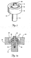
- Fig. 1 shows the individual components of an adjustable locking mounting system 10A.
- Figs. 2 and 3a illustrate the system 10A when assembled.
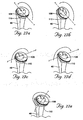
- the system 10A permits adjustment in three directions or three degrees of freedom (rotational around axes x, y, and z, where the z-axis is represented by the axis of the pivot pin 12) (see Figs. 4a-4e ).
- the system 10A comprises the pivot pin 12, at least one slip washer 14, at least one lock washer 16, a mounting hub 18, and a locking screw 20. Each of these components of the system 10A will now be described in detail.
- the pivot pin 12 is a rigid, generally cylindrical or rod-like member.
- the pivot pin 12 is convex, e.g., domed, at one end to couple with the mounting hub 18 (see, e.g., Fig. 3a ).
- the arc of curvature is 0.400" diameter (0.200" radius).
- the convex arrangement permits adjustment of the mounting hub 18 by swinging or tilting across the axis of the pivot pin 12 (i.e., rotation about the x-axis and y-axis) as well as by rotating or twisting about the axis of the pivot pin 12 (i.e., rotation about the z-axis) (see Figs. 4a-4e ).
- the pivot pin 12 has a threaded central bore 26 that serves to receive the locking screw 20.
- the pivot pin 12 serves to receive both the mounting hub 18 and the locking screw 20 (see Fig. 3a ).
- the pivot pin 12 can be made of suitable metal, plastic, or ceramic materials and formed by conventional molding or machining techniques.
- the mounting hub 18 is a rigid member comprising a mounting surface 24, an interior hub 22, and an exterior pivot surface 28.
- the center of the mounting hub 18 serves to receive the locking screw 20.
- the mounting surface 24 is configured to mate with an object or device being mounted on the hub and therefore can take on a variety of shapes.
- the mounting hub 18 serves as a base for mounting of another object or device.
- the mounting surface 24 can be circular or geometric. In the illustrated embodiment, the mounting surface 24 is generally circular.
- the mounting surface 24 can be stepped to further aid in positioning and securing the object or device on the mounting surface 24 (not shown).
- the object or device being mounted would have a complementary stepped surface.
- the stepped surface provides greater control of any adjustment by permitting adjustment to be in uniform increments and reducing the risk of inadvertent movement.
- the mounting surface 24 could alternatively be a threaded surface to facilitate engagement with a mating part.
- the interior hub 22 is open.
- the bottom surface of the interior hub 22 is configured to conform to the shape of the convex end of the pivot pin 12 and sized to receive the slip washer(s) 14 and lock washer(s) 16. That is, the interior hub 22 permits a slip washer 14 and lock washer 16, or multiple slip washers 14 and lock washers 16, to be alternately stacked upon one another (see Fig. 3a ).
- the exterior pivot surface 28 of the mounting hub 18 is configured to nest on and to conform to the convex end of the pivot pin 12, thus permitting a wider range of motion, as previously described.
- the exterior pivot surface 28 is located centrally with respect to the interior hub 22. Further, the interior hub 22 is centrally located with respect to the mounting surface 24, such that the geometric center of the mounting hub 18 coincides with the center of rotation of the mounting hub 18 about the pivot pin 12.
- the mounting hub 18 serves to engage and pivot about the pivot pin 12, thus permitting adjustment of the position of the mounting hub 18 with respect to the pivot pin 12, as will be described later.
- the position of the mounting hub 18 can be locked by use of the locking screw 20, as will also be described in greater detail later.
- the mounting hub 18 can be made of any suitable metal or plastic and formed by conventional machining or molding techniques.
- the system 10A also provides at least one slip washer 14.
- the slip washer 14 is preferably a rigid annular ring or doughnut-like member. As Figs. 1 and 3a best show, the slip washer 14 is configured to conform to the bottom surface of the interior hub 22.
- the center of the slip washer 14 serves to receive the locking screw 20.
- the center of the slip washer 14 is of a diameter only slightly larger than the outside diameter of the locking screw 20.
- the slip washer 14 also serves to provide a frictional surface, which upon tightening of the locking screw 20, serves to further secure the mounting hub 18 in a desired position.
- the slip washer 14 permits the lock washer 16 to slide across the surface of the slip washer 14 (see Figs. 5a and 5b ).
- the slip washer 14 is similar in function yet physically different in top and bottom spherical radii from the lock washer 16.
- R1-R5 spherical radii
- R1-R5 spherical radii
- the radii of the washers 14 and 16 can be varied to accommodate the thickness of the individual washers 14 and 16. Regardless of the thickness or radii of the washers 14 and 16, the washers 14 and 16 are configured to rotate about the same pivot point.
- a second slip washer 14 similar in function but differing in spherical radii from the first slip washer 14 is placed over the lock washer 16.
- the lock washer 16 is able to slide between the slip washers 14.
- the second slip washer 14 provides an additional frictional surface, which upon tightening of the locking screw 20, serves to further secure the desired position.
- the slip washer(s) 14 can be made of any suitable metal or plastic and formed by conventional machining or molding techniques.
- the system 10A further provides a lock washer 16.
- the lock washer 16 is a rigid, annular ring or doughnut-like member similar to the slip washer 14.
- the lock washer 16 is configured to conform to the surface of the slip washer 14. This arrangement permits the lock washer 16 to be stacked on top of the slip washer 14.
- the center of the lock washer 16 serves to receive the locking screw 20.
- the center of the lock washer 16 is also sized larger than the center of the slip washer 14. That is, the center of the lock washer 16 not only serves to receive the locking screw 20, but also permits the lock washer 16 to pivot about the pivot pin 12.
- the lock washer 16 also provides two additional frictional surfaces when sandwiched between two slip washers 14, which upon tightening of the locking screw 20, serve to further secure the desired position.
- the lock washer 16 is of a larger diameter than the slip washer 14. This arrangement allows the lock washer 16 to fit over the slip washer 14.
- the lock washer 16 is sized to approximate or be slightly less than the diameter of the interior hub 22, thereby providing a secure fit of the lock washer 16 within the interior hub 22 and allowing only minimal translation in the x and y axes, yet not restricting z-axis translation of the lock washer 16 within the interior hub 22 and with respect to the axis of the pivot pin 12, as will later be described in detail.
- This arrangement secures/couples the lock washer 16 to the interior hub 22 and permits the lock washer 16 to slide with the mounting hub 18 over the slip washer 14 (see, e.g., Figs. 5a and 5b ).
- the lock washer 16 serves to provide an additional rotational and rocking surface for the mounting hub 18.
- the lock washer 16 can be made of any suitable plastic or metal and formed by conventional molding or machining techniques.
- a second slip washer 14 similar in function but differing in spherical radii from the first slip washer 14 can be provided.
- the lock washer 16 also serves to receive the second slip washer 14. It will be apparent that any number of slip washers 14 and lock washers 16 can be similarly alternately stacked upon each other and thereby accommodate variations in the depth of the interior hub 22.
- the system 10A provides a locking screw 20.
- the locking screw 20 is a screw that is adapted for passage through the mounting hub 18, the slip washer(s) 14, the lock washer(s) 16, and the pivot pin 12 when the system is assembled (see Fig. 3a ).
- In inside the diameter of the slip washer 14 is sized to approximate or be slightly larger than the diameter of the locking screw 20. This arrangement secures/couples the slip washer 14 to the locking screw 20 and the pivot pin 12.
- the locking screw 20 is desirably threaded to fit the threaded bore 26 of the pivot pin 12.
- the locking screw 20 can be made of any suitable plastic or metal and formed by conventional molding or machining techniques.
- the locking screw 20 when not fully tightened, serves to hold the assembly while the desired position is determined. Tightening of the locking screw 20 compresses the washers 14 and 16, hub 18, and pin 12 together, thereby creating multiple frictional forces between the mating surfaces. These frictional forces and the compression of the screw 20 are what limit movement in the locked position.
- plastic slip washers 14 may be alternated with metal lock washers 16.
- the system 10A as previously described enables the mounting hub 18 to be oriented in a variety of directions with respect to the pivot pin 12.
- the types of movement, and thus the types of adjustments permitted, will now be discussed.
- the system 10A permits movement of the mounting hub 18 in at least three rotational directions.
- the mounting hub 18 can be rocked or rotated, i.e., tilted, about the x-axis (i.e., side to side rotation). This motion is permitted by the convex surfaces of the pivot pin 12, mounting hub 18, slip washer(s) 14, and lock washer(s) 16.
- the mounting hub 18 can be rocked or rotated, i.e., tilted, about the y-axis (i.e., front to back rotation). This motion is permitted by the convex surfaces of the pivot pin 12, mounting hub 18, slip washer(s) 14, and lock washer(s) 16.
- the mounting hub 18 can be rotated 360° in either a clockwise or counterclockwise direction about the z-axis (i.e., axis of the pivot pin 12).
- Fig. 6 shows the individual components of an alternative system 10B providing an adjustable locking mount system.
- Figs. 7 and 8 illustrate the system 10B when assembled.
- system 10B comprises a pivot pin 12, at least one slip washer 14, at least one lock washer 16, a mounting hub 18, and a locking screw 20.
- the mounting hub 18 has an exterior pivot surface 28 that is located centrally with respect to the interior hub 22.
- the interior hub 22 is eccentric with respect to the mounting surface 24, such that the geometric center of the mounting hub 18 does not coincide with the center of rotation of the mounting hub 18 about the pivot pin 12.
- the eccentric configuration permits a broader range of adjustment.
- the system 10B as previously described enables the mounting hub 18 to be oriented in a variety of directions with respect to the pivot pin 12.
- the types of movement, and thus the types of adjustments permitted, will now be discussed.
- the system 10B permits movement of the mounting hub 18 in at least five directions.
- the mounting hub 18 can be rocked or rotated about the x-axis, as previously described for system 10A.
- the mounting hub 18 can be rocked or rotated about the y-axis, as also previously described for system 10A.
- the mounting hub 18 can be rotated up to 360° in either direction about the z-axis, as previously described for system 10A.
- the mounting hub 18 when the mounting hub 18 includes an interior hub 22 that is eccentric relative to the mounting surface 24, the distance from the pivot pin 12 to the mounting surface 24 increases to a maximum value, depicted as point A1 and then decreases to a minimum value, depicted as point A2.
- Reorientation of points A1 and A2 with respect to the x-axis provides a fourth degree of freedom.
- reorientation of points A1 and A2 with respect to the y-axis provides a fifth degree of freedom.
- the locking screw 20 is tightened to secure the mounting hub 18 in the desired position, as previously described for System 10A (see Fig. 5c ).
- Figs. 10-23 detail the use of either of the previously described systems 10A or 10B in shoulder replacement surgery. Desirably, system 10B would be employed, thereby providing the greatest range of adjustment. In the embodiment illustrated in Figs. 10-23 , the mount of system 10B is employed.
- the long bone of the upper or proximal arm, as shown in Fig. 16 is known as the humerus 38.
- the proximal end of the humerus 38 comprises a ball-shaped head 40 that normally nests within the glenoid cavity of the shoulder bone, or scapula.
- the head 40 of the humerus 38 can become damaged such that the shape of the head 40 is altered or the head 40 does not fit properly within the glenoid cavity. Such damage typically results in the shoulder joint becoming painful and a corresponding reduction in mobility of the joint.
- the system 10B comprising a pivot pin 12, a mounting hub 18 (with eccentrally located interior hub 22), slip washers 14, a lock washer 16, and a locking screw 20, can be employed within a shoulder replacement assembly 44 suitable for implantation into a humerus 38.
- the system 10B would permit a physician to mount, position, and secure an artificial head 42.
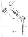
- the replacement assembly comprises a stem 46 including tendon attachment holes 50, an assembled system 10B implanted within the stem 46, a trial ring 48, and an artificial head 42.
- Fig. 11 illustrates the replacement assembly 44 in assembled form.
- the stem 46 is a conventional stem 46 suitable for implantation within a humerus 38.
- the stem 46 desirably includes tendon attachment holes 50 that serve to secure attachment of tendons (not shown) to the stem 46.
- the stem 46 serves to hold the system 10B. That is, the pivot pin 12 is implanted within the stem 46 such that the convex portion protrudes at a pre-selected angle from the stem 46 (e.g., 35°).
- the pivot pin 12 can be implanted within the stem 46 by various techniques.
- the pin 12 is integrally molded with the stem 46.
- the pin 12 can be a separate member configured to mate with an existing stem 46.
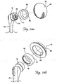
- the pin 12 includes a Morse taper, as seen in Fig. 10 , configured to mate with a complementary tapered surface within the stem 46.
- the pin 12 is configured to mate with the stem 46 by threaded engagement (not shown).
- a trial ring 48 is desirably provided.
- the trial ring 48 is a rigid, generally ring-like member having an inner surface 52 and an outer surface 54.
- the inner surface 52 is desirably eccentric relative to the outer surface 54.
- the trial ring 48 can be made of plastic or any other suitable material.
- the trial ring 48 is adapted to mate with the mounting hub 18, i.e., the trial ring's 48 inner surface 52 geometry approximates the geometry of the mounting surface 24.
- the mounting surface 24 is circular and conically tapered and the trial ring 48 has an inner surface 52 that is complementary circular and tapered.
- the inner surface 52 of the trial ring can be of a geometric or stepped formation adapted to mate with a complementary surface on the mounting surface 24, as previously described (not shown).
- the outer surface 54 of the trial ring 48 desirably has reference markers 56, e.g., A, B, C, and D, spaced circumferentially around the outer surface 54.
- the outer surface 54 is tapered or radiused outward toward the bottom of the trial ring 48 for better visualization of the markers 56.
- the outer surface 54 of the trial ring 48 contains knurls 58.
- the knurls 58 provide for easier grasping of the trial ring 48.
- the outer surface 54 does not contain knurls 58 or the outer surface 54 is otherwise adapted for grasping (not shown).
- the outside diameter 57 of the trial ring 48 corresponds or is equivalent to the outside diameter of the humeral head 42.
- the trial ring 48 is adapted to engage the mounting hub 18 and pivot simultaneously with the mounting hub 18.
- the reference markers 56 can be utilized for evaluation and recording of the desired position, as will be described in greater detail later.
- an artificial head 42 is also provided.
- the artificial head 42 is a rigid, dome-like member having interior 60 and exterior surfaces 62.
- the artificial head 42 can be made of stainless steel or other suitable materials.
- the exterior surface 62 is domed to mimic the ball-like head 40 of the humerus 38.
- the interior surface 60 is recessed and adapted to mate with the mounting surface 24.
- the inner surface 60 is circular.
- the interior surface 60 can be stepped to mate with a complementary mounting surface 24, as previously described (not shown).
- the interior surface 60 desirably has reference markers 56' that are complementary to, i.e., mirror, the reference markers 56 on the trial ring 48. This assures that, when complementary markers 56 and 56' on the trial ring 48 and the artificial head 42 are similarly orientated with respect to the mounting hub 18, the position of the artificial head 42 will be the same as the position of the trial ring 48, as will be explained in greater detail later.
- the recessed inner surface 60 of the artificial head 42 is eccentrally located with respect to the outer surface 62.
- this arrangement When used in combination with the eccentrally located interior hub 22 of system 10B, this arrangement provides a "double-eccentric" system.
- the double-eccentric configuration provides a maximum range of adjustment from O axes offset to up to the maximum axes offset.
- the inner surface 60 of the artificial head 42 is centrally located with respect to the outer surface 62.
- an intermediate collar 63 having an interior surface 59 and an exterior surface 61 can be provided.
- the interior surface 59 of the collar 63 is eccentrally located with respect to the exterior surface 61 and configured to mate with the mounting surface 24.
- the exterior surface 61 is desirably configured to mate with the interior surface 60 of the artificial head 42. This arrangement also results in a double-eccentric configuration.
- the physician makes a cut 65 through the head 40 of the humerus 38 by conventional techniques.
- an interior bore 64 is reamed in the humerus 38 by conventional techniques to prepare the bone for receiving the stem 46.
- the stem 46 incorporating the system 10B, is then inserted within the bore 64, as shown in Fig. 18 . Tendons can then be attached to the stem 46 using the tendon attachment holes 50 (not shown).
- the trial ring 48 is then placed on the mounting hub 18.
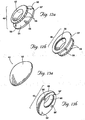
- the eccentric interior hub 22 of the mounting hub 18, together with the eccentric inner surface of the trial ring 48 form a double-eccentric system, as shown in Figs. 19a -19c .
- the trial ring 48 is then rotated simultaneously with the mounting hub 18 until the desired position relative to the cut surface of the humerus 38 is achieved (e.g., center of trial ring 48 is centered with cut surface of humerus 38).
- the trial ring 48 is also adapted to rotate independently of the mounting hub 18.
- the trial ring 48 is tilted (represented by arrows and phantom lines in Fig. 20 ) with the mounting hub 18 until the desired position relative to the cut is achieved (e.g., parallel to cut).
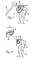
- the mounting hub 18 is then secured in the desired position by tightening (represented by arrow in Fig. 21 ) the locking screw 20, e.g., with an Allen wrench 30.
- the physician can then make a mark 66 on the humerus 38 corresponding to the position of a given reference marker 56 on the trial ring 48 when the mounting hub 18 is properly aligned.
- Fig. 21 illustrates a mark 66 made on the humerus 38 corresponding to the position of reference marker "B" when the trial ring 48 is properly aligned.
- the artificial head 42 is then orientated so that the desired reference marker on the interior surface 60 of the artificial head 42 is aligned with the mark 66 previously made on the humerus 38.
- Fig. 22 illustrates the reference marker "B" on the interior surface 60 of the artificial head 42 being aligned with the mark 66 previously made on the humerus 38.
- the artificial head 42 is then placed (represented by phantom lines in Fig. 22 ) on the mounting hub 18 in this desired orientation.
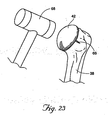
- the physician seats and secures the aligned artificial head 42 in place by hitting the artificial head 42 with a hammer 68 to lock the tapers together before placing the artificial head 42 into position within the glenoid cavity.
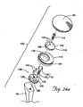
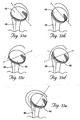
- Figs. 24a-29 detail an alternate embodiment of a shoulder prosthesis mounting system 10C embodying features of the invention.
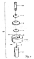
- the system 10C comprises a stem 46, a pivot pin 12, a bottom eccentric insert 108, an eccentric mount 110, a top eccentric insert 112, at least one fastener 114, at least one guidepin 116, and an artificial head 42.
- the stem 46 is a conventional stem suitable for implantation into a humerus and serves to receive the pivot pin 12.
- the pivot pin 12 comprises a ball component 118 and a post component 120.
- the post 120 extends from the ball 118 and is sized to pass through the mount 110 and an eccentric opening 122 on the bottom insert 108 to mate with the stem 46, e.g., by threaded engagement (see e.g., Fig. 24a ) or Morse taper (not shown).
- the post 120 and the ball 118 are not integral.
- the post 120 is integral with the stem 46 and extends from the stem 46.
- the ball 118 is configured to mate with the post 120, e.g., by threaded engagement, and thus is selectively removable from the post 120.
- the stem 46 is configured to carry the post 120 such that the ball 118 protrudes at a pre-selected angle from the stem 46, e.g., 35°. Desirably, a portion of the post 120 remains exterior to the stem 46, enabling the mount 110 to pivot freely on the ball 118 (see Fig. 29 ).
- the eccentric opening 122 is of a larger diameter than the post 120 and sized to permit rotation of the mount 110 about the x , y, and z axes , as will be described in greater detail later.
- the ball 118 is a spherical member sized to rest on the eccentric opening 122 of the bottom insert 108. This arrangement allows the ball 118 to serve as a pivot surface permitting adjustment of the eccentric mount 110.
- the eccentric mount 110 is a ring-like member having an outer surface 124 and an inner surface 126, as seen in Figs. 24a and 24b . As best illustrated in Fig. 24b , the inner surface 126 of the mount 110 is eccentric with respect to the outer surface 124. This arrangement allows the head 42 to be positioned eccentrally with respect to the mount 110. As Figs. 25 and 26 show, the bottom insert 108 has an outer surface 128 adapted to mate with the inner surface 126 of the mount, e.g., by recessed slip fit that is free to rotate.
- At least one guidepin 116 extends from the bottom insert 108.
- three guidepins 116 are employed.
- the guidepins 116 are adapted to pass through complementary guidepin holes 130 on the top insert 112 when the top and bottom inserts 112 and 108 are properly aligned.
- the guidepins 116 serve to help align and secure the top and bottom inserts 112 and 108.
- the top eccentric insert 112 has a top surface 132 and a bottom surface 134.
- the bottom surface 134 has an eccentric recessed area 136 configured to mate with the ball 118.
- the top insert 112 is further adapted to rest on the bottom insert 108.
- the bottom and top inserts 112 and 108 each further comprise at least one fastener opening 138 adapted for passage of a fastener 114, e.g., a screw.
- the fastener 114 when tightened, serves to secure the mount 110 in a desired position by compressing the top and bottom inserts 112 and 108 together around the ball 118 and the mount 110.
- the "stacking" arrangement of the top and bottom inserts 112 and 108 serves to maximize the surface area compressed, thereby aiding in securing the mount 110 in a desired position.
- the eccentric mount 110 along with the eccentric opening 122 of the bottom insert 108 and the eccentric recessed area 136 of the top insert 112 provide a double-eccentric system.
- the artificial head 42 serves as a prosthesis for the head of a humerus, as previously described (see, e.g., Fig. 23 ).
- the recessed interior surface 60 of the head 42 is desirably concentric with respect to the outer surface 62 and is threaded to mate with the outer surface 124 of the mount. Placement of the head 42 onto the mount 110 secures the head to the mount 110 (see Fig. 28 ).
- the system 10C provides at least five degrees of freedom, thereby allowing a wide range of adjustment in multiple dimensions.
- the mount 110 can be rocked or rotated, i.e., tilted, about the x-axis (i.e., side to side rotation).
- the mount 110 can be rocked or rotated, i.e., tilted, about the y-axis (i.e., front to back rotation).
- the mount 110 can be rotated up to 360° in either direction about the z-axis.
- the double eccentric arrangement permits translation of the linear position of points A1 and A2 with respect to the pivot pin 12 when the inserts 108 and 112 and mount 110 are rotated, as previously described for system 10B (see Figs. 7 and 8 ). This action permits translation along the x and y axes.
- the double-eccentric configuration serves to maximize the range of translational adjustment possible under the fourth and fifth types of movement.
- the pivot pin 12 is passed through the bottom insert 108 and the mount 110.
- the pivot pin 12 is then coupled to the stem 46, e.g., by screwing the post 120 into the stem 46.
- the top insert 112 is then aligned with the bottom insert 108 by aligning the fastener openings 138 on the top and bottom inserts 112 and 108, the guidepins 116 with the guidepin holes 130, and the recessed area 136 with the ball 118.
- the position of the mount 110 is then adjusted by rotating or rocking the mount about the x, y, and z axes (see Figs. 27a-27e ).
- the fastener 114 is then tightened to secure the mount 110 in a desired position (not shown).
- the head 42 is mounted onto the mount 110 (see Figs. 28 and 29 ).
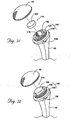
- Figs. 30a-34 detail another embodiment of a shoulder prosthesis mounting system 10D embodying features of the invention.
- the system 10D comprises a stem 46, a pivot pin 12, a mounting ring 140, a bottom disk 142, a top disk 144, an artificial head 42,and a locking tool 146.
- the stem is a conventional stem 46 and serves to receive a pivot pin 12, as previously described for system 10C.
- the pivot pin 12 is similar in configuration to the pivot pin of System 10C.
- the post 120 is adapted to pass through the bottom disk 142 and the mounting ring 140 to mate with the stem 46, e.g., by threaded engagement.
- the ball 118 is sized to rest within the bottom disk 142. This arrangement allows the ball 118 to serve as a pivot surface, thereby permitting adjustment of the mounting ring 140.
- the mounting ring 140 is comprised of an outer ring 148 having a circular marginal surface and an integrally-formed upstanding inner annular ring 150.
- the center of the inner ring defines a chamber 152 and includes an opening 154 permitting passage of the post 120.
- the chamber 152 is configured to receive the bottom disk 142 and the ball 118.
- the outer surface 156 of the inner ring 150 is desirably configured, e.g., threaded, to mate with the interior surface 60 of the head 42.
- the inner ring 150 is concentric with respect to the outer ring 148.
- the invention also contemplates embodiments in which the inner ring 150 is eccentric with respect to the outer ring 148.
- the center opening 154 of the mounting ring 140 is of a larger diameter than the diameter of the post 120 and sized to permit translation of the mounting ring 140 about the x and y axes and rotation about the z-axis, as will be described in greater detail later.
- the mounting ring 140 desirably has a locking aperature 158.
- the aperature 158 is a bore that transverses the circumferential margin of the mounting ring 140 and serves to receive the locking tool 146.
- the locking tool 146 is configured for insertion into the locking aperature 158 and allows rotation of the mounting ring 140 to tighten the head 42 onto the mounting ring 140 (see also Fig. 34 ).
- the bottom disk 142 is a ring-like member having an open center permitting passage of the post 120 and is configured to rest within the chamber 152 and receive the ball 118 (see Figs. 30a-31 ). It is further configured to receive the top disk 144, as illustrated in Fig. 32 .
- the top disk 144 has a top surface 160 and a bottom surface 162.
- the top surface 160 is desirably flat or otherwise configured to permit compression of the top and bottom disks 144 and 142 upon mounting of the head 42 onto the mounting ring 140.
- the bottom surface 162 has a recessed area 164 configured to mate with the ball 118.
- the top disk 144 is further configured to rest on the bottom disk 142 (see also Fig. 32 ).
- This stacking arrangement permits compression of the top and bottom disks 144 and 142 as the head 42 is mounted onto the mounting ring 140 and serves to maximize the surface area compressed, thereby securing the mounting ring 140 in a desired position.
- the artificial head 42 serves as a prosthesis for the head of a humerus, as previously described.
- the recessed interior surface 60 of the head 42 is desirably concentric with respect to the outer surface 62 of the head 42.
- the invention also contemplates, however, embodiments in which the interior surface 60 is eccentric.
- the interior surface 60 of the head 42 is also desirably threaded or otherwise configured to mate with the inner ring 150 of the mounting ring 140.
- system 10D provides at least five degrees of freedom.
- the mounting ring 140 can be rocked or rotated, i.e., tilted, about the x-axis (i.e., side to side rotation).
- the mounting ring 140 can be rocked or rotated, i.e., tilted, about the y-axis (i.e., front to back rotation).
- the mounting ring 140 can be rotated up to 360° in either direction about the z-axis.
- the post 120 is passed through the bottom disk 142 and the mounting ring 140.
- the post 120 is then coupled to the stem 46, e.g., by screwing.
- the top disk 144 is then aligned with the bottom disk 142 by aligning the recessed area 164 with the ball.
- the head 42 is mounted onto the mounting ring 140.
- the position of the head 42 is then adjusted by rotating and rocking the head 42 about the x, y, and z axes (see Figs. 33a-33e ).
- the locking tool 146 is then inserted into the locking aperture 158.
- the mounting ring 140 is then rotated by use of the locking tool 146 to tighten the head 42 onto the mounting ring 140. This action places all the components in compression and fixes the head 42 in place.
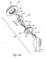
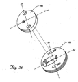
- Figs. 35a-40 detail another embodiment of a shoulder prosthesis mounting system 10E embodying features of the invention.
- the system comprises a stem 46, a pivot pin 12), a bottom plate 166, a top plate 168, at least one fastener 170, and at least one fastening element 172 for securing the fastener 170.
- the stem 46 and pivot pin 12 are configured as previously described for systems 10C and 10D.
- the post 120 is adapted to pass through the bottom plate 166 to mate with the stem 46, e.g., by threaded engagement.
- the ball 118 is sized to rest on the bottom plate 166. This arrangement allows the ball 118 to serve as a pivot surface that permits adjustment of the bottom plate 166.
- the bottom plate 166 is a circular member having a major axis A1 and a minor axis A2.
- An elongated eccentric slot 174 is provided along the major axis A1
- the bottom plate 166 also provides a pair of elongated fixation slots 176 radially spaced from the center and parallel to the major axis A1.
- the fixation slots 176 allow the position of the top plate 168 to be laterally adjusted with respect to the bottom plate 166.
- the fixation slots 176 also serve to receive fasteners 170, e.g., bolts, to secure the position of the top plate 168.
- the eccentric slot 174 receives the ball 118 and allows lateral, i.e., side to side, adjustment (represented by arrows and phantom lines in Fig. 37 ) of the position of the ball 118 within the eccentric slot 174.
- the bottom plate 166 includes a circumferential outer surface 178 configured to mate with the head 42, e.g., by threaded engagement (see e.g., Fig. 35b ).
- the bottom plate 166 serves to receive the top plate 168 in a stacked configuration.
- the top plate 168 is a generally elliptical member having a major axis A3 and a minor axis A4.
- the major axis A3 parallels the minor axis A2 of the bottom plate 166 and the minor axis A4 parallels the major axis A1 of the bottom plate 166 when the top plate 168 is aligned with bottom plate 166.
- the top plate 168 further provides fastener receiving openings 180 sized and configured to receive the fasteners 170.
- the top plate 168 further provides a top surface 182 and a bottom surface 184.
- the top surface 182 is configured to receive a fastening element 172 for the fastener 170, e.g., a nut.
- the bottom surface 184 includes a recessed area 186 configured to mate with the ball 118.
- the recessed area 186 desirably includes an opening 188 adapted for viewing the ball 118, thereby aiding in aligning the top plate 168 with respect to the bottom plate 166.
- the top plate 168 is further configured to rest on the ball 118, leaving a gap between the top plate 168 and bottom plate 166.
- the fasteners 170 when tightened, serve to secure the plates 166 and 168 to the ball 118 in a desired position by compressing the top and bottom plates 166 and 168 together.
- the stacked arrangement of the plates 166 and 168 serves to maximize the surface area compressed, thereby aiding in securing the plates 166 and 168 in the desired position relative to the ball 118.
- the artificial head 42 serves as a prosthesis for the head of a humerus, as previously described.
- the recessed interior surface 60 of the head 42 is desirably concentric with respect to the exterior surface 62 of the head 42, as shown in Fig. 35b . It should be understood, however, that the invention also contemplates embodiments in which the interior surface 60 is eccentric.
- system 10E provides at least five degrees of freedom.
- the bottom plate 166 can be rocked or rotated, i.e., tilted, about the x-axis (i.e., side to side rotation).
- the bottom plate 166 can be rocked or rotated, i.e., tilted, about the y-axis (i.e., front to back rotation).
- the bottom plate 166 can be rotated up to 360° in either direction about the z-axis.
- the slots 176 in the base 166 permit translation of the linear position of the major axis A1 and minor axis A2 with respect to the pivot pin 12 when the bottom plate 166 is slid along the x axis, providing a fourth degree of freedom, or the y axis, providing a fifth degree of freedom.
- the post 120 is passed through the eccentric slot 174 of the bottom plate 166, thereby resting the ball 118 within the slot 174, as seen in Fig. 37 .
- the bottom plate 166 is then slid (illustrated by arrows in Fig. 37 ) along the slot 174 until the desired lateral position is obtained.
- the fasteners 170 are then passed through the fixation slots 176 of the bottom plate 166.
- the top plate 168 is aligned with the bottom plate 166 by aligning the recessed area 186 with the ball 118 and the fastener receiving holes 180 with the fasteners 170.
- the fasteners 170 are then passed through the fixation slots 176 of the bottom plate 166 and the fastener receiving openings 180 on the top plate 168.
- the top plate 168 is thereby positioned to rest on the ball 118 and over bottom plate 166, as Fig. 38 illustrates.
- the position of the plates 166 and 168 is then adjusted by rotating or rocking the bottom plate 166 about the x, y, and z axes (see Figs. 39a-39e ).
- the components of the system 10E can be provided in a fully assembled form in which the user only need tighten the fasteners 170 after adjusting the position of the plates 166 and 168 to secure the plates 166 and 168 in the desired position.
- Fastening elements 172 e.g., nuts
- Fastening elements 172 can be used if desired to tighten and secure the fasteners 170. This action compresses the plates 166 and 168 around the ball 118 to secure the plates 166 and 168 in the desired orientation and location relative to the ball 118.
- the head 42 is mounted onto the bottom plate 166.
Landscapes
- Health & Medical Sciences (AREA)
- Engineering & Computer Science (AREA)
- General Engineering & Computer Science (AREA)
- Transplantation (AREA)
- Mechanical Engineering (AREA)
- Orthopedic Medicine & Surgery (AREA)
- Vascular Medicine (AREA)
- General Health & Medical Sciences (AREA)
- Biomedical Technology (AREA)
- Heart & Thoracic Surgery (AREA)
- Cardiology (AREA)
- Life Sciences & Earth Sciences (AREA)
- Animal Behavior & Ethology (AREA)
- Oral & Maxillofacial Surgery (AREA)
- Public Health (AREA)
- Veterinary Medicine (AREA)
- Physical Education & Sports Medicine (AREA)
- Prostheses (AREA)
- Medicines Containing Plant Substances (AREA)
- Breeding Of Plants And Reproduction By Means Of Culturing (AREA)
- Clamps And Clips (AREA)
Abstract
Description
- This invention generally relates to an adjustable mount assembly and alignment system for a bone prosthesis.
- A shoulder joint consists of a ball-and-socket type coupling of the humerus to the scapula. The humerus forms the ball, and the socket is formed at the glenoid cavity of the scapula. Injury or disease to the joint often results in destruction or deterioration of the head of the humerus, leading to pain and a corresponding loss of mobility and function. In such cases, it is often necessary to provide a replacement joint surface, i.e., a prosthesis, for the head of the humerus that mates with the glenoid cavity.
- The proper alignment of the prosthesis is generally useful to effective performance of the replacement procedure. Typically, the position of the mount is adjusted until the desired position is achieved. The mount is fixed in the desired position and the prosthesis is then secured onto the mount.
- However, conventional mounts provide only a limited range of adjustment, typically allowing only two degrees of freedom, i.e., linearly along an X-axis and Y-axis. The devices that do have more degrees of freedom require multiple trials and a fixture to be used away from the surgical site for proper alignment of the prosthesis to the humerus.
- Further, even upon locking the device in a desired position, conventional mounts may not hold the desired position. This is especially true when force is exerted, e.g., hammering the prosthesis to secure its placement on a mount. "
US-6,197,063 in accordance with the preamble ofpresent claim 1, discloses a modular humeral prosthesis having a stem, a head and a connecting member for connecting the stem to the head". - There remains a need for mounting systems and methods that permit a wide range of adjustment of a humeral head prosthesis while enabling the mount, and attached prosthesis, to remain securely fixed in a desired position.
- The invention provides an adjustable mount assembly according to
claim 1. - The invention makes possible a straightforward, yet robust way of securing, e.g., a humeral head prosthesis in a desired position and maintaining the prosthesis in the desired position during use.
- Other features and advantages of the inventions are set forth in the following specification and attached drawings.
-
-
Fig. 1 is an exploded view of the components of an adjustable locking mount system that embodies features of the invention, in which the mounting hub is centric. -
Fig. 2 is an assembled perspective view of the system shown inFig.1 . -
Fig. 3a is a side sectional view of the assembled components of the system shown in Pig. 2. -
Fig. 3b is a view similar toFig. 3a and illustrating the spherical radii of the stacked washers. -
Figs. 4a-4e illustrate rotational movement of the cooperating components of the assembled system shown inFig. 2 . -
Fig. 5a is a side sectional view of the assembled components of the system shown inFig. 3 and illustrating the system components in a level position. -
Fig. 5b is a sectional view as shown inFig. 5a , illustrating the position of the system components and the movement of the mounting hub and lock washer when the mounting hub is rotated about the x or y axis. -
Fig. 5c is a sectional view as shown inFig. 5b , illustrating the procedure of locking the system in a desired position. -
Fig. 6 is an exploded view of the components of an alternative embodiment of an adjustable locking mount system that embodies features of the invention, in which the mounting hub is eccentric. -
Fig. 7 is an assembled perspective view of the system shown inFig. 6 . -
Figure 8 is side sectional view of the assembled components of the system shown inFig. 7 . -
Figs. 9a-9e illustrate rotational movement of the cooperating components of the assembled system shown inFig. 7 . -
Fig. 10 is an exploded view of an adjustable locking mount system embodying features of the invention incorporated in a shoulder replacement assembly. -
Fig. 11 is a perspective view of the assembled components of the system shown inFig. 10 . -
Fig. 12a is an enlarged perspective view of the top portion of the trial ring shown inFig. 10 . -
Fig. 12b is an enlarged perspective view of the bottom portion of the trial ring shown inFig. 10 . -
Fig. 13a is an enlarged perspective view of the top portion of the artificial head shown inFig. 10 . -
Fig. 13b is an enlarged perspective view of the bottom portion of the artificial head shown inFig. 10 , and further illustrating the interior surface of the artificial head. -
Fig. 14a is an exploded view of the components of an alternate embodiment of a shoulder replacement system embodying features of the invention and viewed from the head to the stem. -
Fig. 14b is a view similar toFig. 14a and viewed from the stem to the head. -
Fig. 15 is a view similar toFigs. 14a and 14b and illustrating a partially assembled view of the system components. -
Fig. 16 is a perspective view of a humerus bone, with a line representing a cut in the ball portion of the humerus made during shoulder replacement surgery. -
Fig. 17 illustrates a humerus as shown inFig. 16 , illustrating the head cut and removed from the humerus and a bore reamed into the bone. -
Fig. 18 is a perspective view illustrating a humerus as shown inFig. 17 , and further illustrating the insertion into the bore of a stem carrying an adjustable mount of the present invention. -
Figs. 19a and 19b are perspective views illustrating a humerus as shown inFig. 18 , and further illustrating a trial ring engaging the mount and being rotated simultaneously with the mount. -
Fig. 19c illustrates the trial being and the mount rotated independently of each other. -
Fig. 20 illustrates a humerus as shown inFigs. 19a and 19b , illustrating the trial ring being simultaneously tilted with the mount. -
Fig. 21 illustrates a humerus as shown inFig. 20 , and further illustrates the procedure of locking the mount in a desired position. -
Fig. 22 shows a humerus as inFig. 21 , with the trial ring removed and illustrating the placement of an artificial head onto the mount. -
Fig. 23 illustrates a humerus as shown inFig. 22 , with the artificial head placed on the mount and further illustrating the use of a hammer to secure the artificial head on the mount. -
Fig. 24a is an exploded view of the components of an alternative embodiment of a shoulder replacement system embodying features of the invention and viewed from the head to the stem. -
Fig. 24b is a view similar toFig. 24a and viewed from the stem to the head. -
Fig. 25 is a view similar toFigs. 24a and24b and illustrating the use and placement of the pivot pin component of the system to secure the bottom insert component onto the stem component. -
Fig. 26 is a view similar toFig. 25 and illustrating the placement of the eccentric mount component onto the bottom insert component. -
Figs. 27a-27e are partially assembled views of the system shown inFigs. 24a and24b and illustrating rotational movement of the partially assembled system. -
Fig. 28 is a partially assembled view of the system shown inFigs. 24a and24b and illustrating the placement of the top insert on the bottom insert. -
Fig. 29 is a perspective view of the components of the system shown in 24a and 24b assembled. -
Fig. 30a is an exploded view of the components of an alternative embodiment of a shoulder replacement system embodying features of the invention and viewed from the head to the stem. -
Fig. 30b is view similar toFig. 30a and viewed from the stem to the head. -
Fig. 31 is a view similar toFigs. 30a and30b illustrating the use of the pivot pin component to secure the mounting ring and the bottom disk to the stem. -
Fig. 32 is a view similar toFig. 31 and illustrating the placement of the top disc on the bottom disk. -
Figs. 33a-33e are views similar toFig. 32 and illustrating the placement of the head component onto the mounting ring component and further illustrating the rotational movement of the assembled system. -
Fig. 34 is a view similar toFigs. 33a-33e and illustrating the locking of the assembled system in a desired position. -
Fig. 35a is an exploded view of an alternative embodiment of a shoulder replacement system embodying features of the invention viewed from the head to the stem. -
Fig. 35b is a view similar toFig. 35a and viewed from the stem to the head. -
Fig. 36 is an exploded view of the bottom and top plate components of the system shown inFigs. 35a and35b and illustrating the major and minor axes of the top and bottom plates. -
Fig. 37 is a partially assembled view of the system shown inFigs. 35a and35b and illustrating the use of the pivot pin to secure the placement of the bottom plate onto to stem. -
Fig. 38 is a view similar toFig. 37 and illustrating the placement of the top plate on the bottom plate. -
Figs. 39a-39e are views similar toFig. 38 and illustrating rotational movement of the partially assembled system. -
Fig. 40 is an assembled view of the system shown inFigs. 35a and35b . - Although the disclosure hereof is detailed and exact to enable those skilled in the art to practice the invention, the physical embodiments herein disclosed merely exemplify the invention that may be embodied in other specific structure. While the preferred embodiment has been described, the details may be changed without departing from the invention, which is defined by the claims.
-
Fig. 1 shows the individual components of an adjustable locking mounting system 10A.Figs. 2 and 3a illustrate the system 10A when assembled. As will be described in detail later, the system 10A permits adjustment in three directions or three degrees of freedom (rotational around axes x, y, and z, where the z-axis is represented by the axis of the pivot pin 12) (seeFigs. 4a-4e ). - The system 10A comprises the
pivot pin 12, at least oneslip washer 14, at least onelock washer 16, a mountinghub 18, and a lockingscrew 20. Each of these components of the system 10A will now be described in detail. - As seen in
Fig. 1 , thepivot pin 12 is a rigid, generally cylindrical or rod-like member. Thepivot pin 12 is convex, e.g., domed, at one end to couple with the mounting hub 18 (see, e.g.,Fig. 3a ). In a representative embodiment, the arc of curvature is 0.400" diameter (0.200" radius). - In particular, the convex arrangement permits adjustment of the mounting
hub 18 by swinging or tilting across the axis of the pivot pin 12 (i.e., rotation about the x-axis and y-axis) as well as by rotating or twisting about the axis of the pivot pin 12 (i.e., rotation about the z-axis) (seeFigs. 4a-4e ). - As best seen in
Figs. 1 and3 , thepivot pin 12 has a threadedcentral bore 26 that serves to receive the lockingscrew 20. Thus, thepivot pin 12 serves to receive both the mountinghub 18 and the locking screw 20 (seeFig. 3a ). - The
pivot pin 12 can be made of suitable metal, plastic, or ceramic materials and formed by conventional molding or machining techniques. - As shown in
Fig. 1 , the mountinghub 18 is a rigid member comprising a mountingsurface 24, aninterior hub 22, and anexterior pivot surface 28. The center of the mountinghub 18 serves to receive the lockingscrew 20. - The mounting
surface 24 is configured to mate with an object or device being mounted on the hub and therefore can take on a variety of shapes. Thus, the mountinghub 18 serves as a base for mounting of another object or device. For example, the mountingsurface 24 can be circular or geometric. In the illustrated embodiment, the mountingsurface 24 is generally circular. - Additionally, the mounting
surface 24 can be stepped to further aid in positioning and securing the object or device on the mounting surface 24 (not shown). In this arrangement, the object or device being mounted would have a complementary stepped surface. The stepped surface provides greater control of any adjustment by permitting adjustment to be in uniform increments and reducing the risk of inadvertent movement. The mountingsurface 24 could alternatively be a threaded surface to facilitate engagement with a mating part. - As best illustrated in
Fig. 1 , theinterior hub 22 is open. The bottom surface of theinterior hub 22 is configured to conform to the shape of the convex end of thepivot pin 12 and sized to receive the slip washer(s) 14 and lock washer(s) 16. That is, theinterior hub 22 permits aslip washer 14 andlock washer 16, ormultiple slip washers 14 and lockwashers 16, to be alternately stacked upon one another (seeFig. 3a ). - As shown in
Figs. 1-3a , theexterior pivot surface 28 of the mountinghub 18 is configured to nest on and to conform to the convex end of thepivot pin 12, thus permitting a wider range of motion, as previously described. - As best seen in
Fig. 3a , theexterior pivot surface 28 is located centrally with respect to theinterior hub 22. Further, theinterior hub 22 is centrally located with respect to the mountingsurface 24, such that the geometric center of the mountinghub 18 coincides with the center of rotation of the mountinghub 18 about thepivot pin 12. - The mounting
hub 18 serves to engage and pivot about thepivot pin 12, thus permitting adjustment of the position of the mountinghub 18 with respect to thepivot pin 12, as will be described later. Upon obtaining the desired position, the position of the mountinghub 18 can be locked by use of the lockingscrew 20, as will also be described in greater detail later. - The mounting
hub 18 can be made of any suitable metal or plastic and formed by conventional machining or molding techniques. - As shown in
Fig. 1 , the system 10A also provides at least oneslip washer 14. Theslip washer 14 is preferably a rigid annular ring or doughnut-like member. AsFigs. 1 and3a best show, theslip washer 14 is configured to conform to the bottom surface of theinterior hub 22. - The center of the
slip washer 14 serves to receive the lockingscrew 20. The center of theslip washer 14 is of a diameter only slightly larger than the outside diameter of the lockingscrew 20. Theslip washer 14 also serves to provide a frictional surface, which upon tightening of the lockingscrew 20, serves to further secure the mountinghub 18 in a desired position. - The
slip washer 14 permits thelock washer 16 to slide across the surface of the slip washer 14 (seeFigs. 5a and 5b ). Theslip washer 14 is similar in function yet physically different in top and bottom spherical radii from thelock washer 16. - As seen in
Fig. 3b ,additional washers Fig. 3b , as they are stacked further from the center of rotation or pivot point on thepivot pin 12. In a representative embodiment, R1 is 0.200, R2 is 0.250, R3 is 0.300, R4 is 0.350, and R5 is 0.400. - The radii of the
washers individual washers washers washers - Desirably, as illustrated in
Figs. 1 and3a , asecond slip washer 14, similar in function but differing in spherical radii from thefirst slip washer 14 is placed over thelock washer 16. As illustrated inFigs. 5a and 5b , thelock washer 16 is able to slide between theslip washers 14. - In this arrangement, the
second slip washer 14 provides an additional frictional surface, which upon tightening of the lockingscrew 20, serves to further secure the desired position. - The slip washer(s) 14 can be made of any suitable metal or plastic and formed by conventional machining or molding techniques.
- As also seen in
Fig. 1 , the system 10A further provides alock washer 16. Thelock washer 16 is a rigid, annular ring or doughnut-like member similar to theslip washer 14. - As
Figs. 1 and3a best illustrate, thelock washer 16 is configured to conform to the surface of theslip washer 14. This arrangement permits thelock washer 16 to be stacked on top of theslip washer 14. - As in the case of the
slip washer 14, the center of thelock washer 16 serves to receive the lockingscrew 20. The center of thelock washer 16 is also sized larger than the center of theslip washer 14. That is, the center of thelock washer 16 not only serves to receive the lockingscrew 20, but also permits thelock washer 16 to pivot about thepivot pin 12. - The
lock washer 16 also provides two additional frictional surfaces when sandwiched between twoslip washers 14, which upon tightening of the lockingscrew 20, serve to further secure the desired position. - As also seen in
Figs. 1 and3a , thelock washer 16 is of a larger diameter than theslip washer 14. This arrangement allows thelock washer 16 to fit over theslip washer 14. In a representative embodiment, thelock washer 16 is sized to approximate or be slightly less than the diameter of theinterior hub 22, thereby providing a secure fit of thelock washer 16 within theinterior hub 22 and allowing only minimal translation in the x and y axes, yet not restricting z-axis translation of thelock washer 16 within theinterior hub 22 and with respect to the axis of thepivot pin 12, as will later be described in detail. - This arrangement secures/couples the
lock washer 16 to theinterior hub 22 and permits thelock washer 16 to slide with the mountinghub 18 over the slip washer 14 (see, e.g.,Figs. 5a and 5b ). Thus, thelock washer 16 serves to provide an additional rotational and rocking surface for the mountinghub 18. - Like the
slip washer 14, thelock washer 16 can be made of any suitable plastic or metal and formed by conventional molding or machining techniques. - Desirably, as previously noted, a
second slip washer 14 similar in function but differing in spherical radii from thefirst slip washer 14 can be provided. In this arrangement, as seen inFigs. 1 and3a , thelock washer 16 also serves to receive thesecond slip washer 14. It will be apparent that any number ofslip washers 14 and lockwashers 16 can be similarly alternately stacked upon each other and thereby accommodate variations in the depth of theinterior hub 22. - As also shown in
Fig. 1 , the system 10A provides a lockingscrew 20. The lockingscrew 20 is a screw that is adapted for passage through the mountinghub 18, the slip washer(s) 14, the lock washer(s) 16, and thepivot pin 12 when the system is assembled (seeFig. 3a ). In inside the diameter of theslip washer 14 is sized to approximate or be slightly larger than the diameter of the lockingscrew 20. This arrangement secures/couples theslip washer 14 to the lockingscrew 20 and thepivot pin 12. - As illustrated in
Fig. 3a , the lockingscrew 20 is desirably threaded to fit the threaded bore 26 of thepivot pin 12. AsFig. 5c illustrates, rotation (represented by arrow inFig. 5c ) of thescrew 20, e.g., by anAllen wrench 30, advances the screw into thepivot pin 12 to fix the mountinghub 18 in a desired position. - The locking
screw 20 can be made of any suitable plastic or metal and formed by conventional molding or machining techniques. - The locking
screw 20, when not fully tightened, serves to hold the assembly while the desired position is determined. Tightening of the lockingscrew 20 compresses thewashers hub 18, and pin 12 together, thereby creating multiple frictional forces between the mating surfaces. These frictional forces and the compression of thescrew 20 are what limit movement in the locked position. - It will be apparent that the components just described can be used in any combination. For example,
plastic slip washers 14 may be alternated withmetal lock washers 16. - The system 10A as previously described enables the mounting
hub 18 to be oriented in a variety of directions with respect to thepivot pin 12. The types of movement, and thus the types of adjustments permitted, will now be discussed. - The system 10A permits movement of the mounting
hub 18 in at least three rotational directions. - First, as represented by arrows in
Figs. 4a-4b , the mountinghub 18 can be rocked or rotated, i.e., tilted, about the x-axis (i.e., side to side rotation). This motion is permitted by the convex surfaces of thepivot pin 12, mountinghub 18, slip washer(s) 14, and lock washer(s) 16. - Second, as represented arrows in
Figs. 4c-4d , the mountinghub 18 can be rocked or rotated, i.e., tilted, about the y-axis (i.e., front to back rotation). This motion is permitted by the convex surfaces of thepivot pin 12, mountinghub 18, slip washer(s) 14, and lock washer(s) 16. - Third, as represented by arrows in
Fig. 4e , the mountinghub 18 can be rotated 360° in either a clockwise or counterclockwise direction about the z-axis (i.e., axis of the pivot pin 12). - It is to be understood that the rotational and rocking movements permit adjustment in virtually an infinite number of rotational directions.
-
Fig. 6 shows the individual components of an alternative system 10B providing an adjustable locking mount system.Figs. 7 and 8 illustrate the system 10B when assembled. - Like system 10A, the system 10B comprises a
pivot pin 12, at least oneslip washer 14, at least onelock washer 16, a mountinghub 18, and a lockingscrew 20. - Also like system 10A, the mounting
hub 18 has anexterior pivot surface 28 that is located centrally with respect to theinterior hub 22. In this embodiment, asFigs. 6-8 best show, theinterior hub 22 is eccentric with respect to the mountingsurface 24, such that the geometric center of the mountinghub 18 does not coincide with the center of rotation of the mountinghub 18 about thepivot pin 12. The eccentric configuration permits a broader range of adjustment. - The system 10B as previously described enables the mounting
hub 18 to be oriented in a variety of directions with respect to thepivot pin 12. The types of movement, and thus the types of adjustments permitted, will now be discussed. - The system 10B permits movement of the mounting
hub 18 in at least five directions. - First, as represented by arrows in
Figs. 9a-9b , the mountinghub 18 can be rocked or rotated about the x-axis, as previously described for system 10A. - Second, as represented by arrows in
Figs. 9c-9d , the mountinghub 18 can be rocked or rotated about the y-axis, as also previously described for system 10A. - Third, as represented by arrows in
Fig. 9e , the mountinghub 18 can be rotated up to 360° in either direction about the z-axis, as previously described for system 10A. - As best illustrated in
Figs. 7 and 8 , when the mountinghub 18 includes aninterior hub 22 that is eccentric relative to the mountingsurface 24, the distance from thepivot pin 12 to the mountingsurface 24 increases to a maximum value, depicted as point A1 and then decreases to a minimum value, depicted as point A2. - Reorientation or translation of the linear position of point A1 and point A2 with respect to the
pivot pin 12 is possible when the mountinghub 18 is rotated about the z-axis. - Reorientation of points A1 and A2 with respect to the x-axis provides a fourth degree of freedom. Similarly, reorientation of points A1 and A2 with respect to the y-axis provides a fifth degree of freedom.
- It is to be understood that the rotational and rocking movements just described permit adjustment in virtually an infinite number of directions.
- After the desired position is obtained, the locking
screw 20 is tightened to secure the mountinghub 18 in the desired position, as previously described for System 10A (seeFig. 5c ). -
Figs. 10-23 detail the use of either of the previously described systems 10A or 10B in shoulder replacement surgery. Desirably, system 10B would be employed, thereby providing the greatest range of adjustment. In the embodiment illustrated inFigs. 10-23 , the mount of system 10B is employed. - The long bone of the upper or proximal arm, as shown in
Fig. 16 , is known as thehumerus 38. The proximal end of thehumerus 38 comprises a ball-shapedhead 40 that normally nests within the glenoid cavity of the shoulder bone, or scapula. - Through disease or injury, the
head 40 of thehumerus 38 can become damaged such that the shape of thehead 40 is altered or thehead 40 does not fit properly within the glenoid cavity. Such damage typically results in the shoulder joint becoming painful and a corresponding reduction in mobility of the joint. - Conventional techniques provide for replacement of the
head 40 of thehumerus 38 with a prosthesis, orartifical head 42. As seen inFig. 10 , the system 10B, comprising apivot pin 12, a mounting hub 18 (with eccentrally located interior hub 22), slipwashers 14, alock washer 16, and a lockingscrew 20, can be employed within ashoulder replacement assembly 44 suitable for implantation into ahumerus 38. The system 10B would permit a physician to mount, position, and secure anartificial head 42. - As shown in
Fig. 10 , the replacement assembly comprises astem 46 including tendon attachment holes 50, an assembled system 10B implanted within thestem 46, atrial ring 48, and anartificial head 42.Fig. 11 illustrates thereplacement assembly 44 in assembled form. - The
stem 46 is aconventional stem 46 suitable for implantation within ahumerus 38. Thestem 46 desirably includes tendon attachment holes 50 that serve to secure attachment of tendons (not shown) to thestem 46. - The
stem 46 serves to hold the system 10B. That is, thepivot pin 12 is implanted within thestem 46 such that the convex portion protrudes at a pre-selected angle from the stem 46 (e.g., 35°). - The
pivot pin 12 can be implanted within thestem 46 by various techniques. In one embodiment, thepin 12 is integrally molded with thestem 46. Alternatively, thepin 12 can be a separate member configured to mate with an existingstem 46. In a representative embodiment, thepin 12 includes a Morse taper, as seen inFig. 10 , configured to mate with a complementary tapered surface within thestem 46. In yet another embodiment, thepin 12 is configured to mate with thestem 46 by threaded engagement (not shown). - As also shown in
Fig. 10 , atrial ring 48 is desirably provided. Thetrial ring 48 is a rigid, generally ring-like member having aninner surface 52 and anouter surface 54. Theinner surface 52 is desirably eccentric relative to theouter surface 54. Thetrial ring 48 can be made of plastic or any other suitable material. - The
trial ring 48 is adapted to mate with the mountinghub 18, i.e., the trial ring's 48inner surface 52 geometry approximates the geometry of the mountingsurface 24. In the embodiment illustrated inFig. 10 , the mountingsurface 24 is circular and conically tapered and thetrial ring 48 has aninner surface 52 that is complementary circular and tapered. - Optionally, the
inner surface 52 of the trial ring can be of a geometric or stepped formation adapted to mate with a complementary surface on the mountingsurface 24, as previously described (not shown). - As shown in
Fig. 12a , theouter surface 54 of thetrial ring 48 desirably hasreference markers 56, e.g., A, B, C, and D, spaced circumferentially around theouter surface 54. - Optionally, as also seen in
Fig. 12a , theouter surface 54 is tapered or radiused outward toward the bottom of thetrial ring 48 for better visualization of themarkers 56. - In the embodiment illustrated in
Figs. 12a and 12b , theouter surface 54 of thetrial ring 48 containsknurls 58. Theknurls 58 provide for easier grasping of thetrial ring 48. Optionally, theouter surface 54 does not containknurls 58 or theouter surface 54 is otherwise adapted for grasping (not shown). Theoutside diameter 57 of thetrial ring 48 corresponds or is equivalent to the outside diameter of thehumeral head 42. - The
trial ring 48 is adapted to engage the mountinghub 18 and pivot simultaneously with the mountinghub 18. In this arrangement, thereference markers 56 can be utilized for evaluation and recording of the desired position, as will be described in greater detail later. - As seen in
Fig. 10 , anartificial head 42 is also provided. Theartificial head 42 is a rigid, dome-likemember having interior 60 and exterior surfaces 62. Theartificial head 42 can be made of stainless steel or other suitable materials. - As best illustrated in
Figs. 11 and13a , theexterior surface 62 is domed to mimic the ball-like head 40 of thehumerus 38. - As seen in
Fig. 13b , theinterior surface 60 is recessed and adapted to mate with the mountingsurface 24. In the embodiment illustrated inFig. 13b , theinner surface 60 is circular. Optionally, theinterior surface 60 can be stepped to mate with a complementary mountingsurface 24, as previously described (not shown). - As
Fig. 13b also shows, theinterior surface 60 desirably has reference markers 56' that are complementary to, i.e., mirror, thereference markers 56 on thetrial ring 48. This assures that, whencomplementary markers 56 and 56' on thetrial ring 48 and theartificial head 42 are similarly orientated with respect to the mountinghub 18, the position of theartificial head 42 will be the same as the position of thetrial ring 48, as will be explained in greater detail later. - Desirably, as in the embodiment illustrated in
Fig. 13b , the recessedinner surface 60 of theartificial head 42 is eccentrally located with respect to theouter surface 62. - When used in combination with the eccentrally located
interior hub 22 of system 10B, this arrangement provides a "double-eccentric" system. The double-eccentric configuration provides a maximum range of adjustment from O axes offset to up to the maximum axes offset. - In an alternate embodiment, shown in
Figs. 14a-14b and 15, theinner surface 60 of theartificial head 42 is centrally located with respect to theouter surface 62. In this arrangement, anintermediate collar 63 having aninterior surface 59 and anexterior surface 61 can be provided. - The
interior surface 59 of thecollar 63 is eccentrally located with respect to theexterior surface 61 and configured to mate with the mountingsurface 24. Theexterior surface 61 is desirably configured to mate with theinterior surface 60 of theartificial head 42. This arrangement also results in a double-eccentric configuration. - In use, as seen in
Fig. 16 , the physician makes acut 65 through thehead 40 of thehumerus 38 by conventional techniques. Next, as shown inFig. 17 , aninterior bore 64 is reamed in thehumerus 38 by conventional techniques to prepare the bone for receiving thestem 46. - The
stem 46, incorporating the system 10B, is then inserted within thebore 64, as shown inFig. 18 . Tendons can then be attached to thestem 46 using the tendon attachment holes 50 (not shown). - The
trial ring 48 is then placed on the mountinghub 18. The eccentricinterior hub 22 of the mountinghub 18, together with the eccentric inner surface of thetrial ring 48 form a double-eccentric system, as shown inFigs. 19a -19c . As represented by arrows inFigs. 19a and 19b , thetrial ring 48 is then rotated simultaneously with the mountinghub 18 until the desired position relative to the cut surface of thehumerus 38 is achieved (e.g., center oftrial ring 48 is centered with cut surface of humerus 38). - As
Fig. 19c shows, thetrial ring 48 is also adapted to rotate independently of the mountinghub 18. - Then, as shown in
Fig. 20 , thetrial ring 48 is tilted (represented by arrows and phantom lines inFig. 20 ) with the mountinghub 18 until the desired position relative to the cut is achieved (e.g., parallel to cut). - As seen in
Fig. 21 , the mountinghub 18 is then secured in the desired position by tightening (represented by arrow inFig. 21 ) the lockingscrew 20, e.g., with anAllen wrench 30. - As also seen in
Fig. 21 , the physician can then make amark 66 on thehumerus 38 corresponding to the position of a givenreference marker 56 on thetrial ring 48 when the mountinghub 18 is properly aligned. - For example,
Fig. 21 illustrates amark 66 made on thehumerus 38 corresponding to the position of reference marker "B" when thetrial ring 48 is properly aligned. - Next, as illustrated in
Fig. 22 , theartificial head 42 is then orientated so that the desired reference marker on theinterior surface 60 of theartificial head 42 is aligned with themark 66 previously made on thehumerus 38. - For example,
Fig. 22 illustrates the reference marker "B" on theinterior surface 60 of theartificial head 42 being aligned with themark 66 previously made on thehumerus 38. - The
artificial head 42 is then placed (represented by phantom lines inFig. 22 ) on the mountinghub 18 in this desired orientation. - Finally, as shown in
Fig. 23 , the physician seats and secures the alignedartificial head 42 in place by hitting theartificial head 42 with ahammer 68 to lock the tapers together before placing theartificial head 42 into position within the glenoid cavity. -
Figs. 24a-29 detail an alternate embodiment of a shoulderprosthesis mounting system 10C embodying features of the invention. With reference toFigs. 24a and24b , thesystem 10C comprises astem 46, apivot pin 12, a bottomeccentric insert 108, aneccentric mount 110, a topeccentric insert 112, at least onefastener 114, at least oneguidepin 116, and anartificial head 42. - The
stem 46 is a conventional stem suitable for implantation into a humerus and serves to receive thepivot pin 12. Thepivot pin 12 comprises aball component 118 and apost component 120. Thepost 120 extends from theball 118 and is sized to pass through themount 110 and aneccentric opening 122 on thebottom insert 108 to mate with thestem 46, e.g., by threaded engagement (see e.g.,Fig. 24a ) or Morse taper (not shown). - In an alternate embodiment, the
post 120 and theball 118 are not integral. Thepost 120 is integral with thestem 46 and extends from thestem 46. Theball 118 is configured to mate with thepost 120, e.g., by threaded engagement, and thus is selectively removable from thepost 120. - In either embodiment, the
stem 46 is configured to carry thepost 120 such that theball 118 protrudes at a pre-selected angle from thestem 46, e.g., 35°. Desirably, a portion of thepost 120 remains exterior to thestem 46, enabling themount 110 to pivot freely on the ball 118 (seeFig. 29 ). - The
eccentric opening 122 is of a larger diameter than thepost 120 and sized to permit rotation of themount 110 about the x , y, and z axes , as will be described in greater detail later. - As seen in
Fig. 25 , theball 118 is a spherical member sized to rest on theeccentric opening 122 of thebottom insert 108. This arrangement allows theball 118 to serve as a pivot surface permitting adjustment of theeccentric mount 110. - The
eccentric mount 110 is a ring-like member having anouter surface 124 and aninner surface 126, as seen inFigs. 24a and24b . As best illustrated inFig. 24b , theinner surface 126 of themount 110 is eccentric with respect to theouter surface 124. This arrangement allows thehead 42 to be positioned eccentrally with respect to themount 110. AsFigs. 25 and26 show, thebottom insert 108 has anouter surface 128 adapted to mate with theinner surface 126 of the mount, e.g., by recessed slip fit that is free to rotate. - With reference again to
Fig. 26 , at least oneguidepin 116 extends from thebottom insert 108. In the illustrated embodiment, threeguidepins 116 are employed. Theguidepins 116 are adapted to pass through complementary guidepin holes 130 on thetop insert 112 when the top andbottom inserts guidepins 116 serve to help align and secure the top andbottom inserts - As best seen in
Fig. 24b , the topeccentric insert 112 has atop surface 132 and abottom surface 134. Thebottom surface 134 has an eccentric recessedarea 136 configured to mate with theball 118. Thetop insert 112 is further adapted to rest on thebottom insert 108. - As best shown in
Fig. 26 , the bottom andtop inserts fastener opening 138 adapted for passage of afastener 114, e.g., a screw. Thefastener 114, when tightened, serves to secure themount 110 in a desired position by compressing the top andbottom inserts ball 118 and themount 110. The "stacking" arrangement of the top andbottom inserts mount 110 in a desired position. - The
eccentric mount 110 along with theeccentric opening 122 of thebottom insert 108 and the eccentric recessedarea 136 of thetop insert 112 provide a double-eccentric system. - The
artificial head 42 serves as a prosthesis for the head of a humerus, as previously described (see, e.g.,Fig. 23 ). AsFig. 24b shows, the recessedinterior surface 60 of thehead 42 is desirably concentric with respect to theouter surface 62 and is threaded to mate with theouter surface 124 of the mount. Placement of thehead 42 onto themount 110 secures the head to the mount 110 (seeFig. 28 ). - The
system 10C provides at least five degrees of freedom, thereby allowing a wide range of adjustment in multiple dimensions. - First, as illustrated by arrows in
Figs. 27a-27b , themount 110 can be rocked or rotated, i.e., tilted, about the x-axis (i.e., side to side rotation). - Second, as illustrated by arrows in
Figs. 27c-27d , themount 110 can be rocked or rotated, i.e., tilted, about the y-axis (i.e., front to back rotation). - Third, as illustrated by arrows in
Fig. 27e , themount 110 can be rotated up to 360° in either direction about the z-axis. - Fourth and fifth, the double eccentric arrangement permits translation of the linear position of points A1 and A2 with respect to the
pivot pin 12 when theinserts Figs. 7 and 8 ). This action permits translation along the x and y axes. - The double-eccentric configuration serves to maximize the range of translational adjustment possible under the fourth and fifth types of movement.
- In use, as shown in
Fig. 25 , thepivot pin 12 is passed through thebottom insert 108 and themount 110. Thepivot pin 12 is then coupled to thestem 46, e.g., by screwing thepost 120 into thestem 46. AsFig. 26 shows, thetop insert 112 is then aligned with thebottom insert 108 by aligning thefastener openings 138 on the top andbottom inserts guidepins 116 with the guidepin holes 130, and the recessedarea 136 with theball 118. - The position of the
mount 110 is then adjusted by rotating or rocking the mount about the x, y, and z axes (seeFigs. 27a-27e ). Thefastener 114 is then tightened to secure themount 110 in a desired position (not shown). Finally, thehead 42 is mounted onto the mount 110 (seeFigs. 28 and29 ). -
Figs. 30a-34 detail another embodiment of a shoulderprosthesis mounting system 10D embodying features of the invention. With reference toFigs. 30a and30b , thesystem 10D comprises astem 46, apivot pin 12, a mountingring 140, abottom disk 142, atop disk 144, anartificial head 42,and alocking tool 146. - The stem is a
conventional stem 46 and serves to receive apivot pin 12, as previously described forsystem 10C. Thepivot pin 12 is similar in configuration to the pivot pin ofSystem 10C. Thepost 120 is adapted to pass through thebottom disk 142 and the mountingring 140 to mate with thestem 46, e.g., by threaded engagement. - As
Fig. 31 shows, theball 118 is sized to rest within thebottom disk 142. This arrangement allows theball 118 to serve as a pivot surface, thereby permitting adjustment of the mountingring 140. - As best seen in
Fig. 30a , the mountingring 140 is comprised of anouter ring 148 having a circular marginal surface and an integrally-formed upstanding innerannular ring 150. The center of the inner ring defines achamber 152 and includes anopening 154 permitting passage of thepost 120. - With reference again to
Fig. 31 , thechamber 152 is configured to receive thebottom disk 142 and theball 118. Theouter surface 156 of theinner ring 150 is desirably configured, e.g., threaded, to mate with theinterior surface 60 of thehead 42. - In the illustrated embodiment, the
inner ring 150 is concentric with respect to theouter ring 148. However, the invention also contemplates embodiments in which theinner ring 150 is eccentric with respect to theouter ring 148. - As best seen in
Fig. 34 , the center opening 154 of the mountingring 140 is of a larger diameter than the diameter of thepost 120 and sized to permit translation of the mountingring 140 about the x and y axes and rotation about the z-axis, as will be described in greater detail later. - As seen in
Fig. 30a , the mountingring 140 desirably has a lockingaperature 158. Theaperature 158 is a bore that transverses the circumferential margin of the mountingring 140 and serves to receive thelocking tool 146. Thelocking tool 146 is configured for insertion into the lockingaperature 158 and allows rotation of the mountingring 140 to tighten thehead 42 onto the mounting ring 140 (see alsoFig. 34 ). - The
bottom disk 142 is a ring-like member having an open center permitting passage of thepost 120 and is configured to rest within thechamber 152 and receive the ball 118 (seeFigs. 30a-31 ). It is further configured to receive thetop disk 144, as illustrated inFig. 32 . - Referring again to
Figs. 30a and30b , thetop disk 144 has atop surface 160 and abottom surface 162. Thetop surface 160 is desirably flat or otherwise configured to permit compression of the top andbottom disks head 42 onto the mountingring 140. Thebottom surface 162 has a recessedarea 164 configured to mate with theball 118. Thetop disk 144 is further configured to rest on the bottom disk 142 (see alsoFig. 32 ). - This stacking arrangement permits compression of the top and
bottom disks head 42 is mounted onto the mountingring 140 and serves to maximize the surface area compressed, thereby securing the mountingring 140 in a desired position. - The
artificial head 42 serves as a prosthesis for the head of a humerus, as previously described. As seen inFig. 30b , the recessedinterior surface 60 of thehead 42 is desirably concentric with respect to theouter surface 62 of thehead 42. The invention also contemplates, however, embodiments in which theinterior surface 60 is eccentric. Theinterior surface 60 of thehead 42 is also desirably threaded or otherwise configured to mate with theinner ring 150 of the mountingring 140. - Similar to
system 10C, thesystem 10D provides at least five degrees of freedom. - First, as illustrated by arrows in
Figs. 33a-33b , the mountingring 140 can be rocked or rotated, i.e., tilted, about the x-axis (i.e., side to side rotation). - Second, as illustrated by arrows in
Figs. 33c-33d , the mountingring 140 can be rocked or rotated, i.e., tilted, about the y-axis (i.e., front to back rotation). - Third, as illustrated by arrows in
Fig. 33e , the mountingring 140 can be rotated up to 360° in either direction about the z-axis. - The difference between the outside diameter of the top and
bottom disks chamber 152 forms a gap, as seen inFig. 32 . This arrangement permits linear translation along the x-axis, providing a fourth degree of freedom, and the y-axis, providing a fifth degree of freedom. - In use, with reference to
Figs. 30a-32 , thepost 120 is passed through thebottom disk 142 and the mountingring 140. Thepost 120 is then coupled to thestem 46, e.g., by screwing. Thetop disk 144 is then aligned with thebottom disk 142 by aligning the recessedarea 164 with the ball. Next, thehead 42 is mounted onto the mountingring 140. - The position of the
head 42 is then adjusted by rotating and rocking thehead 42 about the x, y, and z axes (seeFigs. 33a-33e ). AsFig. 34 illustrates, thelocking tool 146 is then inserted into the lockingaperture 158. As represented by arrows inFig. 34 , the mountingring 140 is then rotated by use of thelocking tool 146 to tighten thehead 42 onto the mountingring 140. This action places all the components in compression and fixes thehead 42 in place. -
Figs. 35a-40 detail another embodiment of a shoulderprosthesis mounting system 10E embodying features of the invention. With reference toFigs. 35a and35b , the system comprises astem 46, a pivot pin 12), abottom plate 166, atop plate 168, at least onefastener 170, and at least onefastening element 172 for securing thefastener 170. - The
stem 46 andpivot pin 12 are configured as previously described forsystems post 120 is adapted to pass through thebottom plate 166 to mate with thestem 46, e.g., by threaded engagement. Theball 118 is sized to rest on thebottom plate 166. This arrangement allows theball 118 to serve as a pivot surface that permits adjustment of thebottom plate 166. - As shown in
Fig. 36 , thebottom plate 166 is a circular member having a major axis A1 and a minor axis A2. An elongatedeccentric slot 174 is provided along the major axis A1 Thebottom plate 166 also provides a pair ofelongated fixation slots 176 radially spaced from the center and parallel to the major axis A1. Thefixation slots 176 allow the position of thetop plate 168 to be laterally adjusted with respect to thebottom plate 166. Thefixation slots 176 also serve to receivefasteners 170, e.g., bolts, to secure the position of thetop plate 168. - As shown in
Fig. 37 , theeccentric slot 174 receives theball 118 and allows lateral, i.e., side to side, adjustment (represented by arrows and phantom lines inFig. 37 ) of the position of theball 118 within theeccentric slot 174. - The
bottom plate 166 includes a circumferentialouter surface 178 configured to mate with thehead 42, e.g., by threaded engagement (see e.g.,Fig. 35b ). Thebottom plate 166 serves to receive thetop plate 168 in a stacked configuration. - Referring again to
Fig. 36 , thetop plate 168 is a generally elliptical member having a major axis A3 and a minor axis A4. The major axis A3 parallels the minor axis A2 of thebottom plate 166 and the minor axis A4 parallels the major axis A1 of thebottom plate 166 when thetop plate 168 is aligned withbottom plate 166. Thetop plate 168 further providesfastener receiving openings 180 sized and configured to receive thefasteners 170. - The
top plate 168 further provides atop surface 182 and abottom surface 184. Thetop surface 182 is configured to receive afastening element 172 for thefastener 170, e.g., a nut. Thebottom surface 184 includes a recessedarea 186 configured to mate with theball 118. The recessedarea 186 desirably includes anopening 188 adapted for viewing theball 118, thereby aiding in aligning thetop plate 168 with respect to thebottom plate 166. Thetop plate 168 is further configured to rest on theball 118, leaving a gap between thetop plate 168 andbottom plate 166. - The
fasteners 170, when tightened, serve to secure theplates ball 118 in a desired position by compressing the top andbottom plates plates plates ball 118. - The
artificial head 42 serves as a prosthesis for the head of a humerus, as previously described. The recessedinterior surface 60 of thehead 42 is desirably concentric with respect to theexterior surface 62 of thehead 42, as shown inFig. 35b . It should be understood, however, that the invention also contemplates embodiments in which theinterior surface 60 is eccentric. - Similar to
systems system 10E provides at least five degrees of freedom. - First, as illustrated by arrows in
Figs. 39a-39b , thebottom plate 166 can be rocked or rotated, i.e., tilted, about the x-axis (i.e., side to side rotation). - Second, as illustrated by arrows in
Figs. 39c-39d , thebottom plate 166 can be rocked or rotated, i.e., tilted, about the y-axis (i.e., front to back rotation). - Third, as illustrated by arrows in
Fig. 39e , thebottom plate 166 can be rotated up to 360° in either direction about the z-axis. - The
slots 176 in the base 166 permit translation of the linear position of the major axis A1 and minor axis A2 with respect to thepivot pin 12 when thebottom plate 166 is slid along the x axis, providing a fourth degree of freedom, or the y axis, providing a fifth degree of freedom. - In assembling the
system 10E, thepost 120 is passed through theeccentric slot 174 of thebottom plate 166, thereby resting theball 118 within theslot 174, as seen inFig. 37 . Thebottom plate 166 is then slid (illustrated by arrows inFig. 37 ) along theslot 174 until the desired lateral position is obtained. Thefasteners 170 are then passed through thefixation slots 176 of thebottom plate 166. - Next, the
top plate 168 is aligned with thebottom plate 166 by aligning the recessedarea 186 with theball 118 and thefastener receiving holes 180 with thefasteners 170. Thefasteners 170 are then passed through thefixation slots 176 of thebottom plate 166 and thefastener receiving openings 180 on thetop plate 168. Thetop plate 168 is thereby positioned to rest on theball 118 and overbottom plate 166, asFig. 38 illustrates. The position of theplates bottom plate 166 about the x, y, and z axes (seeFigs. 39a-39e ). - The components of the
system 10E can be provided in a fully assembled form in which the user only need tighten thefasteners 170 after adjusting the position of theplates plates - Fastening
elements 172, e.g., nuts, can be used if desired to tighten and secure thefasteners 170. This action compresses theplates ball 118 to secure theplates ball 118. - Finally, as seen in
Fig. 40 , thehead 42 is mounted onto thebottom plate 166. - The foregoing is considered as illustrative only of the principles of the invention. Furthermore, since numerous modifications and changes will readily occur to those skilled in the art, it is not desired to limit the invention to the exact construction and operation shown and described.
Claims (11)
- An adjustable mount assembly (10a,10b) for an object comprising:a mounting hub(18) including a mounting surface (24) for the object,a a pivot pin (12) including a first contact surface that is shaped to couple with the mounting hub (18),characterized in that:the mounting hub includes a first concave pivot surface (28) mating with the first contact surface for movement of the mounting hub upon the pivot pin and a second convex pivot surface,and in that the assembly further comprises:a first washer (16), including a third concave pivot surface and a fourth convex pivot surface, the second, third and fourth pivot surfaces being stacked sequentially above the first contact surface, the second and third pivot surfaces facing each other forming a space therebetween, the fourth pivot surface facing away from the third pivot surface;a second washer (14) positioned in the space between the second and third pivot surfaces, the second washer including a second contact surface mating with the second pivot surface and a third contact surface mating with the third pivot surface during movement of the mounting hub upon the pivot pin;a third washer (14) positioned above the fourth pivot surface, the third washer including a fourth contact surface mating with the fourth pivot surface during movement of the mounting hub upon the pivot pin; anda locking screw (20) extending through the mounting hub, the first, second and third washers, and into the pivot pin, and adapted to be rotationally threaded in a threaded bore (26) of the pivot pin in a first direction for compressing the first, second; third, and fourth contact surfaces against the first, second, third, and fourth pivot surfaces, respectively, to create multiple frictional forces between the surfaces that limit movement of the mounting hub upon the pivot pin, and in a second direction that relieves the multiple frictional forces to allow movement of the mounting hub upon the pivot pin.
- An assembly according to claim 1, wherein the third and fourth pivot surfaces comprise, respectively, lower and upper surfaces of the first washer (16) carried by the mounting hub (18).
- An assembly according to any one of claims 1 or 2, wherein the mounting hub is adapted to rotate about an axis on the pivot pin (12).
- An assembly according to any one of claims 1 or 2, wherein the mounting hub (18) is adapted to tilt about an axis on the pivot pin (12).
- An assembly according to any one of claims 1 or 2, wherein the mounting hub (18) is adapted to rotate and tilt about an axis on the pivot pin (12).
- An assembly according to any one of the preceding claims, wherein at least one of the first, second, third, and fourth pivot surfaces is curved along a radius.
- An assembly according to any one of the preceding claims, wherein the first pivot surface includes a center about which the first pivot surface is curved, and
wherein the second, third, and fourth pivot surfaces are curved at successively increasing radii from the center of the first pivot surface. - An assembly according to any one of the preceding claims, wherein the first pivot surface (28) is centric with respect to the mounting surface (24).
- An assembly according to any one of claims 1 to 7, wherein the first pivot surface (28) is eccentric with respect to the mounting surface (24).
- An assembly according to any one of the preceding claims, further comprising a prosthesis sized and configured to be mounted on the mounting surface (24).
- An assembly according to claim 10, wherein the prosthesis is a humeral head prosthesis.
Applications Claiming Priority (5)
| Application Number | Priority Date | Filing Date | Title |
|---|---|---|---|
| US41722 | 1993-04-01 | ||
| US27189501P | 2001-02-27 | 2001-02-27 | |
| US271895P | 2001-02-27 | ||
| US10/041,722 US6736852B2 (en) | 2001-02-27 | 2002-01-08 | Adjustable bone prostheses and related methods |
| PCT/US2002/001145 WO2002067810A2 (en) | 2001-02-27 | 2002-01-16 | Adjustable bone protheses and related methods |
Publications (3)
| Publication Number | Publication Date |
|---|---|
| EP1379200A2 EP1379200A2 (en) | 2004-01-14 |
| EP1379200A4 EP1379200A4 (en) | 2006-08-30 |
| EP1379200B1 true EP1379200B1 (en) | 2011-03-02 |
Family
ID=26718455
Family Applications (1)
| Application Number | Title | Priority Date | Filing Date |
|---|---|---|---|
| EP02705796A Expired - Lifetime EP1379200B1 (en) | 2001-02-27 | 2002-01-16 | Adjustable mount assembly for an object |
Country Status (6)
| Country | Link |
|---|---|
| US (3) | US6736852B2 (en) |
| EP (1) | EP1379200B1 (en) |
| AT (1) | ATE499909T1 (en) |
| AU (1) | AU2002239923A1 (en) |
| DE (1) | DE60239321D1 (en) |
| WO (1) | WO2002067810A2 (en) |
Families Citing this family (117)
| Publication number | Priority date | Publication date | Assignee | Title |
|---|---|---|---|---|
| DE20102819U1 (en) * | 2001-02-17 | 2002-06-27 | K.A. Schmersal Gmbh & Co, 42279 Wuppertal | Safety locking device for a door, flap or the like. |
| US6736852B2 (en) * | 2001-02-27 | 2004-05-18 | Incumed, Inc. | Adjustable bone prostheses and related methods |
| US6942699B2 (en) | 2001-07-11 | 2005-09-13 | Biomet, Inc. | Shoulder prosthesis |
| US8795379B2 (en) | 2001-07-11 | 2014-08-05 | Biomet Manufacturing, Llc | Variable prosthesis |
| US8753402B2 (en) | 2001-07-27 | 2014-06-17 | Biomet Manufacturing, Llc | Modular humeral head resurfacing system |
| US8317871B2 (en) | 2001-07-27 | 2012-11-27 | Biomet Manufacturing Corp. | Modular humeral head resurfacing system |
| US20040162619A1 (en) * | 2001-08-27 | 2004-08-19 | Zimmer Technology, Inc. | Tibial augments for use with knee joint prostheses, method of implanting the tibial augment, and associated tools |
| US20030065397A1 (en) | 2001-08-27 | 2003-04-03 | Hanssen Arlen D. | Prosthetic implant support structure |
| US7892288B2 (en) | 2001-08-27 | 2011-02-22 | Zimmer Technology, Inc. | Femoral augments for use with knee joint prosthesis |
| DE20120703U1 (en) * | 2001-12-21 | 2002-03-07 | KERAMED Medizintechnik GmbH, 07646 Mörsdorf | shoulder prosthesis |
| US7799086B2 (en) * | 2002-04-25 | 2010-09-21 | Zimmer Technology, Inc. | Modular bone implant, tools, and method |
| US8062376B2 (en) * | 2002-07-10 | 2011-11-22 | Biomet Manufacturing Corp. | Shoulder implant assembly |
| US7175663B1 (en) * | 2003-10-08 | 2007-02-13 | Biomet Manufacturing Corp. | Shoulder implant assembly |
| US7452381B2 (en) * | 2003-01-30 | 2008-11-18 | Mayo Foundation For Medical Education And Research | Radial head replacement system |
| US7887544B2 (en) * | 2003-03-10 | 2011-02-15 | Tornier Sas | Ancillary tool for positioning a glenoid implant |
| FR2859099B1 (en) * | 2003-08-25 | 2006-01-06 | Tornier Sa | GLENOIDAL COMPONENT OF SHOULDER PROSTHESIS AND TOTAL SHOULDER PROSTHESIS INCORPORATING SUCH COMPONENT |
| US20050049712A1 (en) * | 2003-08-27 | 2005-03-03 | Ondrla Jeffrey M. | Shoulder Positioning fixture, trials and associated method |
| US20050049710A1 (en) * | 2003-08-28 | 2005-03-03 | O'driscoll Shawn W. | Prosthesis for partial replacement of an articulating surface on bone |
| US8070820B2 (en) | 2003-10-08 | 2011-12-06 | Biomet Manufacturing Corp. | Shoulder implant assembly |
| FR2863865B1 (en) * | 2003-12-19 | 2006-10-06 | Tornier Sa | SHOULDER OR HIP PROSTHESIS AND METHOD OF MOUNTING |
| US8419798B2 (en) * | 2003-12-30 | 2013-04-16 | Depuy Products, Inc. | Joint prosthesis with infinitely positionable head |
| EP1706074B1 (en) * | 2004-01-22 | 2012-12-26 | SQ Products AG | Shoulder joint prosthesis without shaft |
| US7135044B2 (en) * | 2004-03-09 | 2006-11-14 | Howmedics Osteonics Corp. | Modular prosthesis kits |
| ES2622873T3 (en) * | 2004-03-11 | 2017-07-07 | Acumed Llc | Bone replacement systems |
| EP1607069B1 (en) * | 2004-06-15 | 2009-12-23 | Tornier | Inverse-type total shoulder prosthesis |
| FR2871371B1 (en) * | 2004-06-15 | 2007-04-06 | Tornier Sas | GLENOIDAL COMPONENT OF SHOULDER PROSTHESIS, SET OF COMPONENT ELEMENTS OF SUCH COMPONENT AND TOTAL SHOULDER PROSTHESIS INCORPORATING SUCH COMPONENT |
| US8303665B2 (en) | 2004-06-15 | 2012-11-06 | Tornier Sas | Glenoidal component, set of such components and shoulder prosthesis incorporating such a glenoidal component |
| FR2872025B1 (en) | 2004-06-28 | 2006-08-25 | Tornier Sas | PROSTHESIS OF SHOULDER OR HIP |
| US8273093B2 (en) * | 2004-06-29 | 2012-09-25 | Depuy Products, Inc. | Instrumentation for recording and replicating orthopaedic implant orientation |
| US8444698B2 (en) | 2004-12-29 | 2013-05-21 | Depuy Products, Inc. | Joint prosthesis with infinitely positionable head |
| US8460390B2 (en) * | 2004-12-29 | 2013-06-11 | Depuy Products, Inc. | System and method for replicating orthopaedic implant orientation |
| US7998217B1 (en) | 2005-02-02 | 2011-08-16 | Biomet Manufacturing Corp. | Modular offset stem implants |
| US7241069B2 (en) * | 2005-02-07 | 2007-07-10 | Harald Richter | Universal joint arrangement between an apparatus holder and a support arm or a console |
| US7445638B2 (en) * | 2005-03-03 | 2008-11-04 | Biomet France | Humeral implant for shoulder prosthesis |
| US8052758B1 (en) | 2005-03-09 | 2011-11-08 | Biomet Manufacturing Corp. | Method and apparatus for trialing a modular humeral head |
| CA2610672C (en) * | 2005-06-03 | 2013-09-17 | Depuy Ireland Limited | Instrument for use in a joint replacement procedure |
| EP1885296B1 (en) * | 2005-06-03 | 2011-05-18 | LaFosse, Laurent | Instrument for use in a joint replacement procedure |
| US8585706B2 (en) * | 2005-06-03 | 2013-11-19 | Depuy (Ireland) | Instrument for use in a joint replacement procedure |
| US8323347B2 (en) * | 2005-08-25 | 2012-12-04 | Arthrex, Inc. | Shoulder prosthesis |
| US8048167B2 (en) * | 2005-08-30 | 2011-11-01 | Depuy Products, Inc. | Orthopaedic implant kit, orthopaedic surgery kit and associated method |
| WO2007031575A1 (en) * | 2005-09-16 | 2007-03-22 | Zimmer Gmbh | Insert and shell of a joint ball receptacle |
| EP1782765A1 (en) * | 2005-09-23 | 2007-05-09 | Biomet Manufacturing Corp. | Shoulder implant assembly |
| US8679185B2 (en) | 2005-09-30 | 2014-03-25 | DePuy Synthes Products, LLC | Joint prosthesis with positionable head |
| US7708783B2 (en) * | 2005-11-04 | 2010-05-04 | Zimmer Technology, Inc. | Rotating constrained liner |
| EP1787603A1 (en) * | 2005-11-18 | 2007-05-23 | Zimmer GmbH | Basis-platform for an artificial joint |
| WO2007082925A2 (en) * | 2006-01-20 | 2007-07-26 | Zimmer Gmbh | Humeral component |
| WO2007109291A2 (en) | 2006-03-21 | 2007-09-27 | Axiom Orthopaedics, Inc. | Non-spherical articulating surfaces in shoulder and hip prosthesis |
| US20070225821A1 (en) * | 2006-03-21 | 2007-09-27 | Axiom Orthopaedics, Inc. | Femoral and humeral stem geometry and implantation method for orthopedic joint reconstruction |
| EP1996125B1 (en) * | 2006-03-21 | 2013-05-15 | Tornier, Inc. | Glenoid component with improved fixation stability |
| FR2899790B1 (en) * | 2006-04-13 | 2008-06-13 | Tornier Sas | GLENOIDAL COMPONENT FOR TOTAL SHOULDER PROSTHESIS, SET OF SUCH COMPONENTS, AND TOTAL SHOULDER PROSTHESIS COMPRISING SUCH A COMPONENT |
| FR2900045B1 (en) * | 2006-04-21 | 2009-01-16 | Tornier Sas | PROSTHESIS OF SHOULDER OR HIP |
| US20070254012A1 (en) * | 2006-04-28 | 2007-11-01 | Ludwig Florian N | Controlled degradation and drug release in stents |
| US7842093B2 (en) * | 2006-07-18 | 2010-11-30 | Biomet Manufacturing Corp. | Method and apparatus for a knee implant |
| WO2008021972A2 (en) * | 2006-08-10 | 2008-02-21 | Pioneer Surgical Technology, Inc. | Intervertebral disc space sizing tools and methods |
| US20080085151A1 (en) * | 2006-10-04 | 2008-04-10 | Pazdirek Jiri V | Light weight ball joint |
| US7537618B2 (en) * | 2006-11-13 | 2009-05-26 | Howmedica Osteonics Corp. | Modular humeral head |
| US20090287309A1 (en) | 2007-01-30 | 2009-11-19 | Tornier Sas | Intra-articular joint replacement |
| FR2911773B1 (en) * | 2007-01-30 | 2009-03-27 | Tornier Sas | METHOD AND ASSEMBLY OF SURGICAL INSTRUMENTATION FOR POSITIONING A TOTAL REVERSE SHOULDER PROSTHESIS, AND CORRESPONDING PROSTHESIS |
| GB0705911D0 (en) * | 2007-03-28 | 2007-05-09 | Depuy Int Ltd | A head component of an orthopaedic joint prosthesis |
| GB0705905D0 (en) * | 2007-03-28 | 2007-05-09 | Depuy Int Ltd | An Instrument for use in a joint replacement procedure |
| US8257363B2 (en) * | 2007-10-12 | 2012-09-04 | Howmedica Osteonics Corp. | Expandable reverse shoulder trial |
| US7878477B2 (en) * | 2008-01-02 | 2011-02-01 | Lang-Mekra North America, Llc | Multi-axis pivoting detent joint assembly for an exterior vehicle mirror |
| GB0803723D0 (en) * | 2008-02-29 | 2008-04-09 | Depuy Int Ltd | An instrument for use in a joint replacement procedure |
| US7686274B2 (en) * | 2008-04-17 | 2010-03-30 | Lang-Mekra North America Llc | Pivoting detent joint |
| US7875082B2 (en) * | 2008-05-09 | 2011-01-25 | Remi Sciences, Inc. | Ulnar head prosthesis system |
| US8052755B2 (en) * | 2008-05-09 | 2011-11-08 | Remi Sciences, Inc. | Ulnar head prosthesis system |
| US8002838B2 (en) * | 2008-06-11 | 2011-08-23 | Depuy Products, Inc. | Joint prosthesis with positionable head |
| US20110031713A1 (en) * | 2009-08-04 | 2011-02-10 | Ekbundit Michael W | Rod end mounting bushing |
| US9512445B2 (en) * | 2009-08-31 | 2016-12-06 | The Cleveland Clinic Foundation | Humeral joint replacement component |
| GB201006716D0 (en) * | 2010-04-22 | 2010-06-09 | Depuy Ireland | A composite trial prosthesis |
| US9408652B2 (en) | 2010-04-27 | 2016-08-09 | Tornier Sas | Intra-articular joint replacement and method |
| GB201007656D0 (en) | 2010-05-07 | 2010-06-23 | Depuy Ireland Ltd | Rotatable collar for a prosthetesis |
| FR2966343B1 (en) | 2010-10-22 | 2012-12-07 | Tornier Sa | SET OF GLENOIDIAN COMPONENTS OF SHOULDER PROSTHESIS |
| WO2012125795A2 (en) * | 2011-03-16 | 2012-09-20 | Smith & Nephew, Inc. | Compound angle implant |
| US8968412B2 (en) | 2011-06-30 | 2015-03-03 | Depuy (Ireland) | Trialing system for a knee prosthesis and method of use |
| EP2604226A1 (en) | 2011-10-31 | 2013-06-19 | Tornier Orthopedics Ireland Ltd. | Modular reverse shoulder prosthesis |
| US8702804B2 (en) | 2011-12-02 | 2014-04-22 | Biomet Manufacturing, Llc | Variable prosthesis |
| US9421106B2 (en) | 2011-12-07 | 2016-08-23 | Howmedica Osteonics Corp. | Reverse shoulder baseplate with alignment guide for glenosphere |
| US9216086B2 (en) * | 2012-02-01 | 2015-12-22 | Zimmer, Inc. | Adjustable provisional component of a medical device |
| US8945234B2 (en) | 2012-04-26 | 2015-02-03 | Optimus Orthopedic Designs LLC | Prosthesis having a metaphyseal element |
| US8906102B2 (en) | 2012-05-31 | 2014-12-09 | Howmedica Osteonics Corp. | Lateral entry insert for cup trial |
| US8663334B2 (en) | 2012-05-31 | 2014-03-04 | Howmedica Osteonics Corp. | Lateral entry insert for cup trial |
| DE102012211535A1 (en) * | 2012-07-03 | 2014-01-09 | Mahle International Gmbh | Actuator and joint |
| EP2689750B1 (en) * | 2012-07-23 | 2016-08-24 | Tornier Orthopedics Ireland Ltd. | Glenoidal implant for shoulder prosthesis and surgical kit |
| GB2524668A (en) | 2012-09-10 | 2015-09-30 | Acumed Llc | Radial head prosthesis with floating articular member |
| US8771362B2 (en) * | 2012-10-17 | 2014-07-08 | Biomet Manufacturing, Llc | Variable angle humeral components |
| CN104755047B (en) | 2012-10-29 | 2017-05-24 | 东尼尔矫形爱尔兰有限公司 | Systems for Reverse Shoulder Implants |
| US11071635B2 (en) * | 2013-03-08 | 2021-07-27 | Mayo Foundation For Medical Education And Research | Shoulder prosthesis with variable inclination humeral head component |
| US9861491B2 (en) | 2014-04-30 | 2018-01-09 | Depuy Ireland Unlimited Company | Tibial trial system for a knee prosthesis |
| US10575968B2 (en) | 2014-05-16 | 2020-03-03 | Howmedica Osteonics Corp. | Guides for fracture system |
| US9681960B2 (en) | 2014-05-16 | 2017-06-20 | Howmedica Osteonics Corp. | Guides for fracture system |
| FR3029769A1 (en) | 2014-12-10 | 2016-06-17 | Tornier Sa | KIT FOR A PROSTHESIS OF SHOULDER |
| US9566162B2 (en) * | 2015-03-03 | 2017-02-14 | Biomet Manufacturing, Llc | Adjustable humeral tray for shoulder arthroplasty |
| US9597191B2 (en) * | 2015-04-03 | 2017-03-21 | Biomet Manufacturing, Llc | Humeral trial and implant assembly and method of use |
| DE102015108007A1 (en) * | 2015-05-20 | 2016-11-24 | Böllhoff Verbindungstechnik GmbH | Coupling consisting of coupling pin and holder and a method for connecting a first and second component using the coupling |
| US20170049575A1 (en) * | 2015-08-18 | 2017-02-23 | Wright Medical Technology, Inc. | Modular talar fixation method and system |
| US9763792B2 (en) | 2015-10-01 | 2017-09-19 | Acumed Llc | Radial head prosthesis with rotate-to-lock interface |
| US10537445B2 (en) | 2015-10-19 | 2020-01-21 | Depuy Ireland Unlimited Company | Surgical instruments for preparing a patient's tibia to receive an implant |
| US10195056B2 (en) | 2015-10-19 | 2019-02-05 | Depuy Ireland Unlimited Company | Method for preparing a patient's tibia to receive an implant |
| US10390972B2 (en) | 2016-01-15 | 2019-08-27 | Howmedica Osteonics Corp. | Humeral trial adaptor |
| US10363150B1 (en) | 2016-03-29 | 2019-07-30 | American Prosthetic Components, Llc | Prosthetic device with a rotatable pyramid and lateral travel limit |
| WO2017184792A1 (en) | 2016-04-19 | 2017-10-26 | Imascap Sas | Pre-operatively planned humeral implant and planning method |
| EP4032506B1 (en) | 2016-08-24 | 2023-07-26 | Howmedica Osteonics Corp. | Humeral head implant system |
| US9982711B1 (en) * | 2016-11-30 | 2018-05-29 | ECC & Associates, LTD. | Adjustable ball joint |
| EP3558171B1 (en) | 2016-12-21 | 2021-11-03 | Biomet Manufacturing, LLC | Apparatuses for trialing a humeral head |
| CN110191691B (en) | 2017-01-20 | 2022-03-22 | 拜欧米特制造有限责任公司 | Modular expansion component |
| AU2018201313B1 (en) * | 2017-07-12 | 2018-11-01 | Herman Wieland | A swivel joint mechanism for a hand tool |
| EP3678602A4 (en) | 2017-09-08 | 2021-10-06 | Pioneer Surgical Technology, Inc. | INTERVERTEBRAL IMPLANTS, INSTRUMENTS AND PROCESSES |
| USD907771S1 (en) | 2017-10-09 | 2021-01-12 | Pioneer Surgical Technology, Inc. | Intervertebral implant |
| US10968673B2 (en) * | 2018-03-21 | 2021-04-06 | Microsoft Technology Licensing, Llc | Low-pressure friction hinge |
| EP3829494B1 (en) | 2018-07-27 | 2024-08-07 | DePuy Ireland Unlimited Company | Implants |
| CN112804963B (en) | 2018-07-27 | 2024-07-05 | 德普伊爱尔兰无限公司 | Implants, systems, and methods of use thereof |
| AU2020237088B2 (en) * | 2019-03-11 | 2025-09-04 | Shoulder Innovations, Inc. | Total reverse shoulder systems and methods |
| USD938590S1 (en) | 2019-10-01 | 2021-12-14 | Howmedica Osteonics Corp. | Humeral implant |
| AU2021202801A1 (en) | 2020-05-07 | 2021-11-25 | Howmedica Osteonics Corp. | Stemless metaphyseal humeral implant |
| US12004957B2 (en) * | 2020-07-06 | 2024-06-11 | 4S Fx Solutions, LLC | Constrained shoulder and hip arthroplasty |
| EP4255354B1 (en) | 2020-12-03 | 2025-03-26 | Zimmer, Inc. | Apparatuses for trialing a humeral head |
Family Cites Families (42)
| Publication number | Priority date | Publication date | Assignee | Title |
|---|---|---|---|---|
| US362384A (en) | 1887-05-03 | johnson | ||
| US1446164A (en) | 1920-04-01 | 1923-02-20 | D Eyraud Louis | Universal mounting device |
| US1538340A (en) | 1923-08-11 | 1925-05-19 | Hodny William La | Windshield-mirror bracket |
| US3671978A (en) * | 1971-08-09 | 1972-06-27 | Hanger & Co Ltd J E | Angular adjustment devices for use in artificial limb manufacture |
| JPS5523008Y2 (en) | 1975-10-15 | 1980-05-31 | ||
| DE2843633C2 (en) | 1978-10-06 | 1983-04-21 | Daimler-Benz Ag, 7000 Stuttgart | Bracket with guide jaws for a viewing window |
| FR2530945B1 (en) * | 1982-07-30 | 1986-04-18 | Proteor Sa | DEVICE FOR SEARCHING FOR ALIGNMENT, ALIGNMENT AND ORIENTATION OF A PROSTHESIS FOR THIGH OR LEG AMPUTATION |
| US4669766A (en) | 1984-02-10 | 1987-06-02 | Hanchett Entry Systems, Inc. | Door holding magnet |
| US4722502A (en) | 1985-10-02 | 1988-02-02 | American Sterilizer Company | Adjustable support system |
| FR2668654B1 (en) | 1990-10-30 | 1993-04-30 | Alcatel Telspace | FIXING DEVICE IN SPACE. |
| US6083263A (en) | 1991-08-23 | 2000-07-04 | Draenert; Klaus | Adjustable hip-joint endoprosthesis |
| WO1993017640A1 (en) | 1992-03-11 | 1993-09-16 | Phillips L Van | Alignment fixture for prosthetic device |
| DE4238832C1 (en) | 1992-11-17 | 1994-08-11 | Plus Endoprothetik Ag | Shoulder joint endoprosthesis |
| FR2712481B1 (en) | 1993-11-18 | 1996-01-12 | Graf Henry | Improvements to flexible inter-vertebral stabilizers. |
| FR2717756B1 (en) | 1994-03-23 | 1996-05-15 | Journee Paul Sa | Motor vehicle windscreen wiper comprising means for orienting the drive head. |
| US5545230A (en) * | 1994-10-11 | 1996-08-13 | Ohio Willow Wood Company | Prosthesis mounting adapter and method |
| KR970025573A (en) | 1995-11-09 | 1997-06-24 | 황성관 | Artificial hip |
| US5727569A (en) | 1996-02-20 | 1998-03-17 | Cardiothoracic Systems, Inc. | Surgical devices for imposing a negative pressure to fix the position of cardiac tissue during surgery |
| CA2197614C (en) | 1996-02-20 | 2002-07-02 | Charles S. Taylor | Surgical instruments and procedures for stabilizing the beating heart during coronary artery bypass graft surgery |
| WO1998008467A1 (en) | 1996-08-30 | 1998-03-05 | Hunter Innovations, Inc. | Adjustable modular orthopedic implant |
| US5895428A (en) | 1996-11-01 | 1999-04-20 | Berry; Don | Load bearing spinal joint implant |
| GB9707371D0 (en) | 1997-04-11 | 1997-05-28 | Minnesota Mining & Mfg | A modular humeral prosthesis |
| DE29708050U1 (en) | 1997-05-07 | 1997-07-17 | Riess, Andreas, 22850 Norderstedt | Arrangement for the local immobilization of a beating heart |
| WO1999016367A1 (en) | 1997-09-26 | 1999-04-08 | Alliance Medical Technologies, Inc. | Stabilizer |
| US6007486A (en) | 1997-10-07 | 1999-12-28 | Ethicon Endo-Surgery, Inc. | Tissue stabilization device for use during surgery having a segmented shaft |
| FR2771280B1 (en) | 1997-11-26 | 2001-01-26 | Albert P Alby | RESILIENT VERTEBRAL CONNECTION DEVICE |
| EP0923908B1 (en) | 1997-12-17 | 2003-04-23 | Robert Lange | Apparatus for stabilizing certain vertebrae of the spine |
| US5921695A (en) | 1997-12-23 | 1999-07-13 | Ingersoll-Rand Company | Ergonomically adjustable tool handle having a dual direction locking device |
| FR2773469B1 (en) | 1998-01-09 | 2000-03-03 | Alain Leonard | SURGICAL EQUIPMENT FOR THE IMPLANTATION OF A TOTAL SHOULDER PROSTHESIS, AND TOTAL SHOULDER PROSTHESIS |
| US6511512B2 (en) * | 1998-04-10 | 2003-01-28 | Ossur Hf | Active shock module prosthesis |
| US6126689A (en) * | 1998-06-15 | 2000-10-03 | Expanding Concepts, L.L.C. | Collapsible and expandable interbody fusion device |
| US6302887B1 (en) | 1998-07-20 | 2001-10-16 | Joseph John Spranza | Hardware for high strength fastening of bone |
| AU758587B2 (en) | 1998-09-15 | 2003-03-27 | Medtronic, Inc. | Method and apparatus for temporarily immobilizing a local area of tissue |
| WO2000062684A1 (en) * | 1999-04-16 | 2000-10-26 | Nuvasive, Inc. | Systems for securing facet joints together |
| US6171039B1 (en) | 1999-05-11 | 2001-01-09 | Nokia Telecommunications Oy | Locking mechanism for connector |
| US6319252B1 (en) | 1999-07-23 | 2001-11-20 | Mcdevitt Dennis | System and method for attaching soft tissue to bone |
| US6273390B1 (en) | 1999-10-20 | 2001-08-14 | Royal Capital Stamping And Tooling Ltd. | Post holder with upright adjustment |
| US6248132B1 (en) | 1999-10-29 | 2001-06-19 | Charles C. Harris | Hip replacement prosthesis |
| WO2001049193A1 (en) * | 2000-01-03 | 2001-07-12 | Orthoscope Ltd. | Intramedullary support strut |
| ATE387161T1 (en) * | 2001-01-25 | 2008-03-15 | Smith & Nephew Inc | RETAINING DEVICE FOR HOLDING A PROSTHETIC COMPONENT |
| US6736852B2 (en) * | 2001-02-27 | 2004-05-18 | Incumed, Inc. | Adjustable bone prostheses and related methods |
| US6688798B2 (en) * | 2001-02-27 | 2004-02-10 | Incumed, Inc. | Adjustable locking mount and methods of use |
-
2002
- 2002-01-08 US US10/041,722 patent/US6736852B2/en not_active Expired - Fee Related
- 2002-01-16 DE DE60239321T patent/DE60239321D1/en not_active Expired - Lifetime
- 2002-01-16 AU AU2002239923A patent/AU2002239923A1/en not_active Abandoned
- 2002-01-16 WO PCT/US2002/001145 patent/WO2002067810A2/en not_active Ceased
- 2002-01-16 EP EP02705796A patent/EP1379200B1/en not_active Expired - Lifetime
- 2002-01-16 AT AT02705796T patent/ATE499909T1/en not_active IP Right Cessation
-
2004
- 2004-01-29 US US10/767,673 patent/US7166132B2/en not_active Expired - Fee Related
-
2007
- 2007-01-22 US US11/656,285 patent/US20070118230A1/en not_active Abandoned
Also Published As
| Publication number | Publication date |
|---|---|
| WO2002067810A2 (en) | 2002-09-06 |
| EP1379200A4 (en) | 2006-08-30 |
| US6736852B2 (en) | 2004-05-18 |
| US7166132B2 (en) | 2007-01-23 |
| US20020120339A1 (en) | 2002-08-29 |
| AU2002239923A1 (en) | 2002-09-12 |
| EP1379200A2 (en) | 2004-01-14 |
| US20070118230A1 (en) | 2007-05-24 |
| ATE499909T1 (en) | 2011-03-15 |
| DE60239321D1 (en) | 2011-04-14 |
| WO2002067810A3 (en) | 2003-07-17 |
| US20040186579A1 (en) | 2004-09-23 |
Similar Documents
| Publication | Publication Date | Title |
|---|---|---|
| US6736852B2 (en) | Adjustable bone prostheses and related methods | |
| US20220211506A1 (en) | Method of Preparing Joint Prosthesis With Infinitely Positionable Head | |
| JP5420580B2 (en) | Prosthetic assembly with positionable head | |
| US7083651B2 (en) | Spinal implant | |
| US5169399A (en) | Acetabular cup impactor | |
| EP1550420B1 (en) | Joint prosthesis with adjustable head | |
| EP1080702B1 (en) | Humeral prosthesis | |
| US6749637B1 (en) | Endoprosthesis for a shoulder joint | |
| US7115144B2 (en) | Spinal implant |
Legal Events
| Date | Code | Title | Description |
|---|---|---|---|
| PUAI | Public reference made under article 153(3) epc to a published international application that has entered the european phase |
Free format text: ORIGINAL CODE: 0009012 |
|
| 17P | Request for examination filed |
Effective date: 20030918 |
|
| AK | Designated contracting states |
Kind code of ref document: A2 Designated state(s): AT BE CH CY DE DK ES FI FR GB GR IE IT LI LU MC NL PT SE TR |
|
| AX | Request for extension of the european patent |
Extension state: AL LT LV MK RO SI |
|
| A4 | Supplementary search report drawn up and despatched |
Effective date: 20060801 |
|
| 17Q | First examination report despatched |
Effective date: 20080611 |
|
| RTI1 | Title (correction) |
Free format text: ADJUSTABLE MOUNT ASSEMBLY FOR AN OBJECT |
|
| GRAP | Despatch of communication of intention to grant a patent |
Free format text: ORIGINAL CODE: EPIDOSNIGR1 |
|
| GRAS | Grant fee paid |
Free format text: ORIGINAL CODE: EPIDOSNIGR3 |
|
| RAP1 | Party data changed (applicant data changed or rights of an application transferred) |
Owner name: TORNIER, INC. |
|
| GRAA | (expected) grant |
Free format text: ORIGINAL CODE: 0009210 |
|
| AK | Designated contracting states |
Kind code of ref document: B1 Designated state(s): AT BE CH CY DE DK ES FI FR GB GR IE IT LI LU MC NL PT SE TR |
|
| REG | Reference to a national code |
Ref country code: GB Ref legal event code: FG4D |
|
| REG | Reference to a national code |
Ref country code: CH Ref legal event code: EP |
|
| REG | Reference to a national code |
Ref country code: IE Ref legal event code: FG4D |
|
| REF | Corresponds to: |
Ref document number: 60239321 Country of ref document: DE Date of ref document: 20110414 Kind code of ref document: P |
|
| REG | Reference to a national code |
Ref country code: DE Ref legal event code: R096 Ref document number: 60239321 Country of ref document: DE Effective date: 20110414 |
|
| REG | Reference to a national code |
Ref country code: CH Ref legal event code: NV Representative=s name: R. A. EGLI & CO. PATENTANWAELTE |
|
| REG | Reference to a national code |
Ref country code: NL Ref legal event code: VDEP Effective date: 20110302 |
|
| PG25 | Lapsed in a contracting state [announced via postgrant information from national office to epo] |
Ref country code: GR Free format text: LAPSE BECAUSE OF FAILURE TO SUBMIT A TRANSLATION OF THE DESCRIPTION OR TO PAY THE FEE WITHIN THE PRESCRIBED TIME-LIMIT Effective date: 20110603 Ref country code: ES Free format text: LAPSE BECAUSE OF FAILURE TO SUBMIT A TRANSLATION OF THE DESCRIPTION OR TO PAY THE FEE WITHIN THE PRESCRIBED TIME-LIMIT Effective date: 20110613 Ref country code: SE Free format text: LAPSE BECAUSE OF FAILURE TO SUBMIT A TRANSLATION OF THE DESCRIPTION OR TO PAY THE FEE WITHIN THE PRESCRIBED TIME-LIMIT Effective date: 20110302 |
|
| PG25 | Lapsed in a contracting state [announced via postgrant information from national office to epo] |
Ref country code: AT Free format text: LAPSE BECAUSE OF FAILURE TO SUBMIT A TRANSLATION OF THE DESCRIPTION OR TO PAY THE FEE WITHIN THE PRESCRIBED TIME-LIMIT Effective date: 20110302 Ref country code: NL Free format text: LAPSE BECAUSE OF FAILURE TO SUBMIT A TRANSLATION OF THE DESCRIPTION OR TO PAY THE FEE WITHIN THE PRESCRIBED TIME-LIMIT Effective date: 20110302 Ref country code: FI Free format text: LAPSE BECAUSE OF FAILURE TO SUBMIT A TRANSLATION OF THE DESCRIPTION OR TO PAY THE FEE WITHIN THE PRESCRIBED TIME-LIMIT Effective date: 20110302 Ref country code: CY Free format text: LAPSE BECAUSE OF FAILURE TO SUBMIT A TRANSLATION OF THE DESCRIPTION OR TO PAY THE FEE WITHIN THE PRESCRIBED TIME-LIMIT Effective date: 20110302 |
|
| PG25 | Lapsed in a contracting state [announced via postgrant information from national office to epo] |
Ref country code: BE Free format text: LAPSE BECAUSE OF FAILURE TO SUBMIT A TRANSLATION OF THE DESCRIPTION OR TO PAY THE FEE WITHIN THE PRESCRIBED TIME-LIMIT Effective date: 20110302 |
|
| PG25 | Lapsed in a contracting state [announced via postgrant information from national office to epo] |
Ref country code: PT Free format text: LAPSE BECAUSE OF FAILURE TO SUBMIT A TRANSLATION OF THE DESCRIPTION OR TO PAY THE FEE WITHIN THE PRESCRIBED TIME-LIMIT Effective date: 20110704 |
|
| PLBE | No opposition filed within time limit |
Free format text: ORIGINAL CODE: 0009261 |
|
| STAA | Information on the status of an ep patent application or granted ep patent |
Free format text: STATUS: NO OPPOSITION FILED WITHIN TIME LIMIT |
|
| 26N | No opposition filed |
Effective date: 20111205 |
|
| PG25 | Lapsed in a contracting state [announced via postgrant information from national office to epo] |
Ref country code: DK Free format text: LAPSE BECAUSE OF FAILURE TO SUBMIT A TRANSLATION OF THE DESCRIPTION OR TO PAY THE FEE WITHIN THE PRESCRIBED TIME-LIMIT Effective date: 20110302 |
|
| REG | Reference to a national code |
Ref country code: DE Ref legal event code: R097 Ref document number: 60239321 Country of ref document: DE Effective date: 20111205 |
|
| PG25 | Lapsed in a contracting state [announced via postgrant information from national office to epo] |
Ref country code: IT Free format text: LAPSE BECAUSE OF FAILURE TO SUBMIT A TRANSLATION OF THE DESCRIPTION OR TO PAY THE FEE WITHIN THE PRESCRIBED TIME-LIMIT Effective date: 20110302 |
|
| PG25 | Lapsed in a contracting state [announced via postgrant information from national office to epo] |
Ref country code: MC Free format text: LAPSE BECAUSE OF NON-PAYMENT OF DUE FEES Effective date: 20120131 |
|
| PGFP | Annual fee paid to national office [announced via postgrant information from national office to epo] |
Ref country code: GB Payment date: 20121228 Year of fee payment: 12 |
|
| PGFP | Annual fee paid to national office [announced via postgrant information from national office to epo] |
Ref country code: DE Payment date: 20130131 Year of fee payment: 12 Ref country code: FR Payment date: 20130128 Year of fee payment: 12 Ref country code: CH Payment date: 20130129 Year of fee payment: 12 Ref country code: IE Payment date: 20130104 Year of fee payment: 12 |
|
| PG25 | Lapsed in a contracting state [announced via postgrant information from national office to epo] |
Ref country code: TR Free format text: LAPSE BECAUSE OF FAILURE TO SUBMIT A TRANSLATION OF THE DESCRIPTION OR TO PAY THE FEE WITHIN THE PRESCRIBED TIME-LIMIT Effective date: 20110302 |
|
| PG25 | Lapsed in a contracting state [announced via postgrant information from national office to epo] |
Ref country code: LU Free format text: LAPSE BECAUSE OF NON-PAYMENT OF DUE FEES Effective date: 20120116 |
|
| REG | Reference to a national code |
Ref country code: DE Ref legal event code: R119 Ref document number: 60239321 Country of ref document: DE |
|
| REG | Reference to a national code |
Ref country code: CH Ref legal event code: PL |
|
| GBPC | Gb: european patent ceased through non-payment of renewal fee |
Effective date: 20140116 |
|
| PG25 | Lapsed in a contracting state [announced via postgrant information from national office to epo] |
Ref country code: CH Free format text: LAPSE BECAUSE OF NON-PAYMENT OF DUE FEES Effective date: 20140131 Ref country code: DE Free format text: LAPSE BECAUSE OF NON-PAYMENT OF DUE FEES Effective date: 20140801 Ref country code: LI Free format text: LAPSE BECAUSE OF NON-PAYMENT OF DUE FEES Effective date: 20140131 |
|
| REG | Reference to a national code |
Ref country code: FR Ref legal event code: ST Effective date: 20140930 |
|
| REG | Reference to a national code |
Ref country code: IE Ref legal event code: MM4A |
|
| REG | Reference to a national code |
Ref country code: DE Ref legal event code: R119 Ref document number: 60239321 Country of ref document: DE Effective date: 20140801 |
|
| PG25 | Lapsed in a contracting state [announced via postgrant information from national office to epo] |
Ref country code: GB Free format text: LAPSE BECAUSE OF NON-PAYMENT OF DUE FEES Effective date: 20140116 Ref country code: FR Free format text: LAPSE BECAUSE OF NON-PAYMENT OF DUE FEES Effective date: 20140131 |
|
| PG25 | Lapsed in a contracting state [announced via postgrant information from national office to epo] |
Ref country code: IE Free format text: LAPSE BECAUSE OF NON-PAYMENT OF DUE FEES Effective date: 20140116 |