EP1379101B1 - Speaker arrangement for communication terminal - Google Patents
Speaker arrangement for communication terminal Download PDFInfo
- Publication number
- EP1379101B1 EP1379101B1 EP02077565A EP02077565A EP1379101B1 EP 1379101 B1 EP1379101 B1 EP 1379101B1 EP 02077565 A EP02077565 A EP 02077565A EP 02077565 A EP02077565 A EP 02077565A EP 1379101 B1 EP1379101 B1 EP 1379101B1
- Authority
- EP
- European Patent Office
- Prior art keywords
- speaker
- terminal
- communication terminal
- recited
- user interface
- Prior art date
- Legal status (The legal status is an assumption and is not a legal conclusion. Google has not performed a legal analysis and makes no representation as to the accuracy of the status listed.)
- Expired - Lifetime
Links
- 238000004891 communication Methods 0.000 title claims abstract description 52
- 230000005236 sound signal Effects 0.000 claims description 6
- 239000004020 conductor Substances 0.000 claims description 2
- 238000013461 design Methods 0.000 description 12
- LVROLHVSYNLFBE-UHFFFAOYSA-N 2,3,6-trichlorobiphenyl Chemical compound ClC1=CC=C(Cl)C(C=2C=CC=CC=2)=C1Cl LVROLHVSYNLFBE-UHFFFAOYSA-N 0.000 description 8
- 230000008901 benefit Effects 0.000 description 5
- 230000005540 biological transmission Effects 0.000 description 4
- 230000001419 dependent effect Effects 0.000 description 4
- 238000011161 development Methods 0.000 description 4
- 238000009877 rendering Methods 0.000 description 3
- PEZNEXFPRSOYPL-UHFFFAOYSA-N (bis(trifluoroacetoxy)iodo)benzene Chemical compound FC(F)(F)C(=O)OI(OC(=O)C(F)(F)F)C1=CC=CC=C1 PEZNEXFPRSOYPL-UHFFFAOYSA-N 0.000 description 2
- 230000001413 cellular effect Effects 0.000 description 1
- 230000007812 deficiency Effects 0.000 description 1
- 238000005516 engineering process Methods 0.000 description 1
- 230000003993 interaction Effects 0.000 description 1
- 238000009533 lab test Methods 0.000 description 1
- 239000004973 liquid crystal related substance Substances 0.000 description 1
- 238000004519 manufacturing process Methods 0.000 description 1
- 238000000034 method Methods 0.000 description 1
- 238000003825 pressing Methods 0.000 description 1
- 238000012360 testing method Methods 0.000 description 1
Images

Classifications
-
- H—ELECTRICITY
- H04—ELECTRIC COMMUNICATION TECHNIQUE
- H04M—TELEPHONIC COMMUNICATION
- H04M1/00—Substation equipment, e.g. for use by subscribers
- H04M1/02—Constructional features of telephone sets
- H04M1/03—Constructional features of telephone transmitters or receivers, e.g. telephone hand-sets
- H04M1/035—Improving the acoustic characteristics by means of constructional features of the housing, e.g. ribs, walls, resonating chambers or cavities
-
- H—ELECTRICITY
- H04—ELECTRIC COMMUNICATION TECHNIQUE
- H04M—TELEPHONIC COMMUNICATION
- H04M1/00—Substation equipment, e.g. for use by subscribers
- H04M1/02—Constructional features of telephone sets
- H04M1/03—Constructional features of telephone transmitters or receivers, e.g. telephone hand-sets
Definitions
- the present invention relates generally to a communication terminal comprising an antenna for wireless communication purposes, and a speaker for conveying audio information to a user of the communication terminal. More specifically the invention relates to a communication terminal wherein such a speaker is arranged inside the resonance chamber of said antenna.
- the mobile phone industry has had an enormous development both regarding quality of service and transmission capabilities, as well as the technology for producing advanced communications terminals.
- the communication systems have gone from analogue to digital, and at the same time the dimensions of the communication terminals have gone from briefcase size to the pocket size phones of today.
- mobile phones are getting smaller and smaller and the size is generally considered to be an important factor for the end customer.
- the development in electronics has made it possible to miniaturise the components of the terminals, at the same time making the terminals capable of performing more advanced functions and services.
- the future generation of phones will have a large display in order to perform multimedia input and output, and the picture quality will be of high importance. Still, the keypad or keyboard must be large enough to allow people to press one key at the time.
- Figure 1 discloses a typical example of a state of the art mobile phone 1, carried by a housing or chassis 2.
- the size of a keypad 4 and a display 3 basically sets the limit of how small the terminal 1 can be.
- the terminal 1 also includes a microphone 5 and a speaker 6, preferably arranged at opposite ends of the terminal 1.
- Figure 3 discloses a different embodiment of a state of the art communication terminal 1, wherein the display 3 occupies a larger portion of the front side of the terminal.
- Several of the functions of the keypad 4 have been included in a graphical user interface applicable to the display 3, rendering a data input interface having less keys.
- Those keys 4 may also be moved to the side of the communication terminal in order to allow for the display 3 to occupy a larger portion of the front side of terminal 1.
- a specific tool 8 may be provided for inputting data on a touch-sensitive screen of the display 3.
- Figs 1 and 3 show two typical examples of state of the art communication terminals 1, whereas the skilled persons will realise that combinations of the two are also well known as well as other designs.
- the speaker of the terminal may also be used as a ringer instead of a traditional buzzer, for a single tone or polyphonic ring signals, and as a hand free speaker built-in into the phone. Normally, these functions are performed by a second speaker mounted in the back of the phone, but combined speakers for two or all three of these functions exist.
- a terminal output 7 is mounted on the front of the terminal above the display with the speaker 6 immediately behind the output 7, as shown in figs 1 and 3 .
- the antenna of the terminal is generally located at the upper portion of the backside of the terminal, the lower backside being occupied by a battery. Placing the speaker 6 behind the display 3 would therefore increase the thickness of the terminal 1 since it would have to compete with the antenna for the relevant space.
- the performance of the speaker is to a high extent dependent on the back volume, i.e. the acoustic resonance cavity behind the speaker.
- the back volume should be sealed.
- the whole phone is used as back volume, but it is almost possible to seal a phone.
- almost every phone today has the speaker position in the upper parts of the front of the terminal above the display and keyboard. This means that the height of the speaker, display and the keyboard determines the length of the phone. Since the speaker performances is highly dependent on the dimension, reduction of the speaker size results in less good acoustics.
- WO 00/38475 A solution to this problem of miniaturisation of communication terminals is proposed in WO 00/38475 , in which the acoustic resonance chamber of the speaker is completely or partly located in the electromagnetic resonance chamber of the antenna.
- the use of a single resonance chamber instead of two separate ones makes it possible to manufacture smaller communication devices.
- the speaker is placed outside the resonance chamber, the backside of the speaker being connected to the resonance chamber by at least one acoustic channel.
- the arrangement of the speaker beside the resonance chamber has some drawbacks. First of all the acoustic channel has to be properly sealed. Furthermore, the speaker and chamber will both add to the thickness of the terminal, and at the same time the height of the speaker will contribute to the length of the terminal.
- communication terminal comprising a housing carrying therein a radio antenna element, a speaker, and a chamber acting as an electromagnetic resonance cavity for the antenna as well as an acoustic resonance cavity for the speaker.
- the speaker is mounted inside said chamber and is coupled to the outside of the housing through a sound outlet.
- a good resonance chamber is provided for the speaker.
- the thickness contribution of the speaker is eliminated. Tests performed on a prototype apparatus have shown the surprising result that the speaker will not, or to a very little extent, affect the performance of the antenna.
- the communication terminal comprises a user interface on a front side of the housing, wherein said speaker is placed behind said user interface as seen from said front side.
- the user interface may be a display or a key pad.
- said sound outlet is preferably coupled to said speaker by a sound channel which extends from a channel inlet at the speaker.
- said sound channel preferably comprises at least one bent portion, such that the sound channel bends around said user interface and extends at said channel front outlet substantially perpendicular to said front side.
- Said sound channel may further be devised with a channel top outlet extending in a substantially longitudinal direction of the terminal at a top side of said housing.
- a ground plane defines a wall part of the chamber, through which wall part said sound channel outlet extends.
- the speaker is preferably mounted under said ground plane, as seen from said front side.
- the chamber may further be sealed, and have a substantially rectangular box shape.
- the speaker and the user interface are placed next to each other.
- a first part of the ground plane is located adjacent to the front part of the housing over the speaker antenna
- a second part of the ground plane is located under the user interface, wherein said first and second parts are connected by a bent portion of the ground plane.
- said antenna element comprises a substantially flat pattern of conductive material on an inner wall of said chamber.
- the speaker may be devised to convey audio information such as speech to a terminal user.
- the speaker may comprise a buzzer devised to act as a ringer by transmitting a predetermined sound signal to bring a user's attention to the terminal.
- said speaker may be a multi mode actuator devised to act as a ringer and a vibrator by transmitting predetermined sound signals or vibrations to bring a user's attention to the terminal.
- the present description refers to communications terminals as a device in which to implement the speaker configuration according to the present invention.
- the communication terminal includes all mobile equipment devised for radio communication with a radio station, which radio station also may be a mobile terminal or e.g. a stationary base station. Consequently, the term "communication terminal” includes mobile phones, pagers, communicators, electronic organisers, smart phones, PDA:s (Personal Digit Assistants), vehicle-mounted radio communication devices or the like, as well as portable laptop computers devised for wireless communication in for instance WLAN (Wireless Local Area Network).
- WLAN Wireless Local Area Network
- the term "communication terminal” should also be understood as to include any stationary device arranged for radio communication, such as for instance desk top computers, printers, fax machines and so on, devised to operate with radio communication with each other or some other radio station.
- any stationary device arranged for radio communication such as for instance desk top computers, printers, fax machines and so on, devised to operate with radio communication with each other or some other radio station.
- the structure and characteristics of the antenna design according to the invention is mainly described herein, by way of example, in the implementation in a mobile phone, this is not to be interpreted as excluding the implementation of the inventive design in other types of radio terminals, such as those listed above.
- Fig 4 illustrates one embodiment of the present invention as seen from the front side.
- Fig 6 illustrates a portion of fig 4 as seen from section A - - A indicated in fig 4 . It should be noted, though, that the drawing in fig 6 is equally applicable to an embodiment of the present invention as shown in for example fig 2 .
- fig 6 illustrates a portion of a communication terminal 11 as seen from the side, with the front side 20 facing left in the drawing.
- Terminal 11 comprises a Printed Circuit Board (PCB) 24 carried in a chassis or housing 12.
- the PCB 24 supports the electronics 25 of terminal 11.
- a display 13 is located, preferably devised as a LCD module (Liquid Crystal Display). As shown in the example of figs 4 and 5 the display 13 may occupy a major portion of the front side 20, whereas in a more traditional design according to fig 2 , the display is mainly located at upper parts of the terminal.
- LCD module Liquid Crystal Display
- a radio antenna 29 of terminal 11 is arranged.
- PCB 24 includes a ground plane towards the antenna 29, which antenna is devised for reception and transmission of radio signals according to the established art.
- the specific design of the radio antenna 29, which may e.g. be a micro strip antenna or a PIFA antenna (Planar Inverted-F Antenna), is not of importance for the present invention, although the invention relates to antennas which demand a cavity or distance between the antenna element and the ground plane.
- the antenna 29 is some form of low profile flat antenna formed or placed on the inside of an antenna lid 27.
- the feeding connection of antenna 29 to the PCB is not shown, neither is a connection to the ground plane which may be included dependent on the antenna type.
- the antenna 29 is situated at a certain distance from the PCB 24, such that an electromagnetic resonance cavity 21 is located there between, in a manner well known in the art.
- a chamber 21 acting as the electromagnetic resonance cavity is preferably a sealed box defined between the antenna lid 27, the PCB 24, and side walls, and the chamber 21 is sealed by gaskets 26.
- a speaker 16 is located inside chamber 21 and mounted adjacent PCB 24 with gaskets 26, such that the front side of speaker 16, illustrated in the drawing by the curved portion, is sealed from the cavity of chamber 21. This way, chamber 21 will also act as an acoustic resonance cavity for speaker 16.
- the front side of speaker 16 is coupled to the outside of the housing 12 through a sound channel 22 to an output opening 17 in housing 12.
- Sound channel 22 includes a channel inlet 28 forming an opening in the PCB 24 to the front side of speaker 16.
- speaker 16 is located behind the display 13, and the length or height of speaker 16 is not added to the total length of terminal 11. It should be noted though, that in an alternative design of communication terminal 11 (not shown) in which the display is arranged at the bottom of the phone near a microphone 15, and a key pad 14 is arranged at the top of the phone, speaker 16 would be located behind key pad 14 rather than display 13. By placing speaker 16 inside chamber 21, the thickness of 16 does not add to the total thickness of terminal 11, thereby rendering a smaller terminal.
- the height of speaker 16 does not add to the length of terminal 11. Instead, only the height of the outlet 17 of sound channel 22 will add to the length of the phone.
- the terminal 11 of fig 2 is obviously shorter in the longitudinal direction than terminal 1 of fig 1 .
- the inventive design is disclosed in figs 4 and 5 . Comparing the embodiment of terminal 11 in fig 4 with the state of the art terminal 1 of fig 3 , terminal 11 is clearly smaller.
- an auxiliary tool 8 may be used to interact with the phone by pressing touch sensitive areas of display 3, 13 in a manner well known in the art.
- sound channel 22 comprises at least one bent portion 23, such that the sound channel bends round the user interface 13, 14 in front of speaker 16.
- sound channel 22 exits at the front side 20 of terminal 11 substantially perpendicular thereto, as illustrated by the arrow at outlet 17.
- the sound channel 22 further has a sound channel top outlet 19, exiting in a substantially longitudinal direction of terminal 11 at a top side of housing 12, as illustrated by the arrow at outlet 19. This outlet 19 may be used as a hands-free speaker outlet.
- FIG. 7A a state of the art terminal much like the one in Fig. 1 is shown from the front side.
- Fig. 7B the same terminal is schematically illustrated from the side in a sectional view with the front side facing left.
- a ground plane 24 is arranged in the terminal extending longitudinally through a part, or substantially the entire body, of the terminal. Normally, this ground plane is a layer of a printed circuit boards carrying the electronics of the terminal.
- a speaker 6 is placed at the front side of the terminal, over the ground plane as seen from the front side.
- the back of the speaker is coupled to the cavity 21, placed behind the ground plane, through an opening in the ground plane as illustrated in the drawing.
- the back wall of cavity 21, i.e. the wall opposite to the ground plane carries an antenna element, e.g. in the shape of a PIFA.
- a user interface comprises a display 3 and a key pad 4, and a microphone 5 is placed at the bottom of the terminal.
- a battery 9 is further included to supply the terminal electronics with electrical power.
- Figs 8A and 8B an embodiment of the present invention is disclosed, in which the speaker 16 is placed beside the user interface 13, rather than under as in the embodiments of Figs 2 , 4 , 5 and 6 .
- the speaker 16 is placed inside the antenna cavity 21, in order to benefit from the same space for acoustic purposes, as previously described.
- the thickness of the terminal is in this embodiment basically defined by the distance between the antenna and the ground plane, since the thickness contribution from the speaker has been eliminated.
- the antenna cavity 21 has been partly occupied by the speaker, experimental laboratory tests on this design have surprisingly shown that the presence of the speaker will not result in reduced antenna performance if tuned properly.
- Figs 7B and 8B indicate that the entire terminal can be made thinner by implementation of this embodiment. Naturally, this is dependent on the dimensions of the user interface, the battery, other electronics, and so on, and the arrangement of these elements.
- Fig. 8B further shows a feature relating to the ground plane.
- a first, upper, part of the ground plane defines the front face of the terminal, although it is preferably covered by a housing directly adjacent to the ground plane 24. Since the user interface, e.g. the display 13, has a certain thickness, the ground plane has a bent portion between the speaker and the user interface, wherein the ground plane first bends downwards towards the back side of the terminal, and then bends back towards the lower end carrying the microphone 15.
- a second, lower, part of the ground plane is formed which extends in a plane closer to the back of the terminal than the first part.
- the purpose of the antenna cavity is to place the antenna at a certain distance from the ground plane. For this reason it is likewise important in the present embodiment that the bent portion is not to close to the antenna, such that the uppermost edge of the lower part of the ground plane is located too close to the antenna. In other words, a certain minimum distance between the antenna and ground can be defined, and no part of the ground plane may be placed closer to the antenna than that.
- Chamber 21 acting as a cavity for both acoustic resonance and electromagnetic resonance may be a rectangular box, which makes it easy to seal by means of gaskets 26.
- antenna 29 may be a separate conductive element placed on the inside of the antenna lid 27 but may also be a conductive pattern coated on the inside of lid 27.
- the present invention brings about several advantages, thanks to the inventive idea to mount the speaker inside the antenna cavity, where the antenna cavity is a sealed box.
- the front side of speaker 16 is ported to the terminal front 20 by a thin channel 22.
- This solution can also be used when the speaker 16 performs in more than one mode. Consequently, speaker 16 can be used as a ringer in ringer mode, and also as a hands-free speaker in speakerphone mode.
- Porting the speaker to the front of the terminal by use of a sound channel 22 makes it possible to reduce the length of terminal 11 by five to ten millimetres and still keep the thickness at a minimum.
- the weight of the terminal 11 may be reduced due to the smaller terminal dimension.
- the antenna cavity of chamber 21 is used to create a distance between antenna 29 and the ground plane of PCB 24 in order to improve the bandwidth of the antenna, as is well known in the prior arts. Otherwise this cavity is normally not used for anything else. Furthermore, by placing speaker 16 inside cavity 21, the function of chamber 21 as an electromagnetic cavity will not be effected in any negative way, and will therefore not disturb the performance of terminal 11.
Abstract
Description
- The present invention relates generally to a communication terminal comprising an antenna for wireless communication purposes, and a speaker for conveying audio information to a user of the communication terminal. More specifically the invention relates to a communication terminal wherein such a speaker is arranged inside the resonance chamber of said antenna.
- The mobile phone industry has had an enormous development both regarding quality of service and transmission capabilities, as well as the technology for producing advanced communications terminals. In only a couple of decades the communication systems have gone from analogue to digital, and at the same time the dimensions of the communication terminals have gone from briefcase size to the pocket size phones of today. Still today, mobile phones are getting smaller and smaller and the size is generally considered to be an important factor for the end customer. The development in electronics has made it possible to miniaturise the components of the terminals, at the same time making the terminals capable of performing more advanced functions and services. The development of new transmission schemes, the so-called 3rd generation mobile system standing at the door and the 4th generation to be expected maybe ten years later, also provides the possibility to convey more advanced data to the wireless communication terminals, such as real time video.
- In order to benefit from the capabilities of the transmission system, the future generation of phones will have a large display in order to perform multimedia input and output, and the picture quality will be of high importance. Still, the keypad or keyboard must be large enough to allow people to press one key at the time.
-
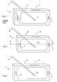
Figure 1 discloses a typical example of a state of the artmobile phone 1, carried by a housing orchassis 2. The size of akeypad 4 and adisplay 3 basically sets the limit of how small theterminal 1 can be. However, to be able to work as a standard phone for voice interaction, theterminal 1 also includes amicrophone 5 and aspeaker 6, preferably arranged at opposite ends of theterminal 1.Figure 3 discloses a different embodiment of a state of theart communication terminal 1, wherein thedisplay 3 occupies a larger portion of the front side of the terminal. Several of the functions of thekeypad 4 have been included in a graphical user interface applicable to thedisplay 3, rendering a data input interface having less keys. Thosekeys 4 may also be moved to the side of the communication terminal in order to allow for thedisplay 3 to occupy a larger portion of the front side ofterminal 1. Aspecific tool 8 may be provided for inputting data on a touch-sensitive screen of thedisplay 3.Figs 1 and3 show two typical examples of state of theart communication terminals 1, whereas the skilled persons will realise that combinations of the two are also well known as well as other designs. - With the development of the communication systems and the capabilities of multimedia functions, the demands on the sound quality from the terminals will also increase. In the next generation of terminals using W-CDMA technique, it will be possible to use a wider audio frequency band. The speaker of the terminal may also be used as a ringer instead of a traditional buzzer, for a single tone or polyphonic ring signals, and as a hand free speaker built-in into the phone. Normally, these functions are performed by a second speaker mounted in the back of the phone, but combined speakers for two or all three of these functions exist.
- In the state of the art communication terminal a
terminal output 7 is mounted on the front of the terminal above the display with thespeaker 6 immediately behind theoutput 7, as shown infigs 1 and3 . This means that even with a smallest available speaker used today, with a diameter of about 13 mm, the terminal would be approximately this much longer in its longitudinal extension than what would have been the case if only thedisplay 3 and/orkeypad 4 had defined the length of theterminal 1. The antenna of the terminal is generally located at the upper portion of the backside of the terminal, the lower backside being occupied by a battery. Placing thespeaker 6 behind thedisplay 3 would therefore increase the thickness of theterminal 1 since it would have to compete with the antenna for the relevant space. - The performance of the speaker is to a high extent dependent on the back volume, i.e. the acoustic resonance cavity behind the speaker. For best performance, the back volume should be sealed. In a normal case the whole phone is used as back volume, but it is almost possible to seal a phone. As mentioned above, almost every phone today has the speaker position in the upper parts of the front of the terminal above the display and keyboard. This means that the height of the speaker, display and the keyboard determines the length of the phone. Since the speaker performances is highly dependent on the dimension, reduction of the speaker size results in less good acoustics. There is also a general desire to have larger displays in the communication terminal, not just wider but also longer, and with the common layout of the keyboard such as disclosed in
figure 1 and which people are used to, the height of the terminal can basically not be reduced more than today without resulting drawbacks to thedisplay 3 orkeypad 4. - A solution to this problem of miniaturisation of communication terminals is proposed in
WO 00/38475 - Other solutions are presented in
EP 1 184 936 AWO 01/01591 - It is consequently an object of the present invention to overcome the deficiencies related to the state of the art communication terminal as recited above. More specifically, it is an object to provide a speaker arrangement for a communication terminal making it possible to decrease the outer terminal dimensions. According to the present invention, this object is fulfilled by communication terminal comprising a housing carrying therein a radio antenna element, a speaker, and a chamber acting as an electromagnetic resonance cavity for the antenna as well as an acoustic resonance cavity for the speaker. According to the invention, the speaker is mounted inside said chamber and is coupled to the outside of the housing through a sound outlet. By using the antenna cavity a good resonance chamber is provided for the speaker. Furthermore, by placing the speaker inside the cavity, the thickness contribution of the speaker is eliminated. Tests performed on a prototype apparatus have shown the surprising result that the speaker will not, or to a very little extent, affect the performance of the antenna.
- In one embodiment, the communication terminal comprises a user interface on a front side of the housing, wherein said speaker is placed behind said user interface as seen from said front side. The user interface may be a display or a key pad. In such an embodiment, said sound outlet is preferably coupled to said speaker by a sound channel which extends from a channel inlet at the speaker. Furthermore, said sound channel preferably comprises at least one bent portion, such that the sound channel bends around said user interface and extends at said channel front outlet substantially perpendicular to said front side. Said sound channel may further be devised with a channel top outlet extending in a substantially longitudinal direction of the terminal at a top side of said housing.
- In one embodiment, a ground plane defines a wall part of the chamber, through which wall part said sound channel outlet extends. The speaker is preferably mounted under said ground plane, as seen from said front side. The chamber may further be sealed, and have a substantially rectangular box shape.
- In one embodiment, the speaker and the user interface are placed next to each other. However, a first part of the ground plane is located adjacent to the front part of the housing over the speaker antenna, and a second part of the ground plane is located under the user interface, wherein said first and second parts are connected by a bent portion of the ground plane. This way the top portion of the terminal, comprising the antenna and the speaker, will basically be confined between the ground plane, i.e. the first part thereof, and the antenna element, rendering a very slim profile. The bent portion allows for the two parts of the ground plane to be arranged at different levels, though potentially parallel to each other. This way the user interface, which has a certain thickness, can be positioned with its front face basically in the same plane as the front side of the top portion.
- Preferably said antenna element comprises a substantially flat pattern of conductive material on an inner wall of said chamber.
- The speaker may be devised to convey audio information such as speech to a terminal user. Furthermore, the speaker may comprise a buzzer devised to act as a ringer by transmitting a predetermined sound signal to bring a user's attention to the terminal. Alternatively, said speaker may be a multi mode actuator devised to act as a ringer and a vibrator by transmitting predetermined sound signals or vibrations to bring a user's attention to the terminal.
- Further features and advantages of the present invention will become more apparent from the following description of preferred embodiments, with reference to the accompanying drawings, on which
-
Fig 1 schematically shows a state of the art communication terminal of a first type; -
Fig 2 schematically illustrates an embodiment of a communication terminal according to the present invention, otherwise designed according to the terminal type offig 1 ; -
Fig 3 schematically illustrates a second type of terminal according to the state of the art; -
Figs 4 and 5 illustrate embodiments of communication terminals according to the present invention otherwise designed according to the terminal type offig 3 ; -
Fig 6 schematically illustrates a sectional side view of a portion of a communication terminal according to an embodiment of the present invention; -
Figs 7A and 7B illustrate a state of the art communication terminal in a front view and a sectional side view; and -
Figs 8A and 8B illustrate a terminal according to an embodiment of the invention in a front view and a sectional side view. - The present description refers to communications terminals as a device in which to implement the speaker configuration according to the present invention. The communication terminal includes all mobile equipment devised for radio communication with a radio station, which radio station also may be a mobile terminal or e.g. a stationary base station. Consequently, the term "communication terminal" includes mobile phones, pagers, communicators, electronic organisers, smart phones, PDA:s (Personal Digit Assistants), vehicle-mounted radio communication devices or the like, as well as portable laptop computers devised for wireless communication in for instance WLAN (Wireless Local Area Network). Furthermore, since the design and present invention is suitable for but not restricted to mobile use, the term "communication terminal" should also be understood as to include any stationary device arranged for radio communication, such as for instance desk top computers, printers, fax machines and so on, devised to operate with radio communication with each other or some other radio station. Hence, although the structure and characteristics of the antenna design according to the invention is mainly described herein, by way of example, in the implementation in a mobile phone, this is not to be interpreted as excluding the implementation of the inventive design in other types of radio terminals, such as those listed above. Furthermore, it should be emphasised that the term "comprising" or "comprises" when used in this description and in the appended claims to indicate included features, elements or steps, is in no way to be interpreted as excluding the presence of other features, elements or steps than those expressed or stated.
-
Fig 4 illustrates one embodiment of the present invention as seen from the front side.Fig 6 illustrates a portion offig 4 as seen from section A - - A indicated infig 4 . It should be noted, though, that the drawing infig 6 is equally applicable to an embodiment of the present invention as shown in for examplefig 2 . - Consequently,
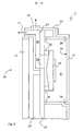
fig 6 illustrates a portion of acommunication terminal 11 as seen from the side, with thefront side 20 facing left in the drawing. It should be noted thatfig 6 is highly schematic, intended to show the principal of an embodiment of the present invention and not necessarily a functioning design.Terminal 11 comprises a Printed Circuit Board (PCB) 24 carried in a chassis orhousing 12. ThePCB 24 supports theelectronics 25 ofterminal 11. At the front side 20 adisplay 13 is located, preferably devised as a LCD module (Liquid Crystal Display). As shown in the example offigs 4 and 5 thedisplay 13 may occupy a major portion of thefront side 20, whereas in a more traditional design according tofig 2 , the display is mainly located at upper parts of the terminal. Behind thedisplay 13 andPCB 24, aradio antenna 29 ofterminal 11 is arranged.PCB 24 includes a ground plane towards theantenna 29, which antenna is devised for reception and transmission of radio signals according to the established art. The specific design of theradio antenna 29, which may e.g. be a micro strip antenna or a PIFA antenna (Planar Inverted-F Antenna), is not of importance for the present invention, although the invention relates to antennas which demand a cavity or distance between the antenna element and the ground plane. In the illustrated embodiment offig 6 , however, theantenna 29 is some form of low profile flat antenna formed or placed on the inside of anantenna lid 27. The feeding connection ofantenna 29 to the PCB is not shown, neither is a connection to the ground plane which may be included dependent on the antenna type. Theantenna 29 is situated at a certain distance from thePCB 24, such that anelectromagnetic resonance cavity 21 is located there between, in a manner well known in the art. Achamber 21 acting as the electromagnetic resonance cavity is preferably a sealed box defined between theantenna lid 27, thePCB 24, and side walls, and thechamber 21 is sealed bygaskets 26. - A
speaker 16 is located insidechamber 21 and mountedadjacent PCB 24 withgaskets 26, such that the front side ofspeaker 16, illustrated in the drawing by the curved portion, is sealed from the cavity ofchamber 21. This way,chamber 21 will also act as an acoustic resonance cavity forspeaker 16. The front side ofspeaker 16 is coupled to the outside of thehousing 12 through asound channel 22 to anoutput opening 17 inhousing 12.Sound channel 22 includes achannel inlet 28 forming an opening in thePCB 24 to the front side ofspeaker 16. - Consequently,
speaker 16 is located behind thedisplay 13, and the length or height ofspeaker 16 is not added to the total length ofterminal 11. It should be noted though, that in an alternative design of communication terminal 11 (not shown) in which the display is arranged at the bottom of the phone near amicrophone 15, and akey pad 14 is arranged at the top of the phone,speaker 16 would be located behindkey pad 14 rather thandisplay 13. By placingspeaker 16 insidechamber 21, the thickness of 16 does not add to the total thickness ofterminal 11, thereby rendering a smaller terminal. - By placing
speaker 16, andcavity 21, behind the user interface, i.e. thedisplay 13 orkeypad 14, the height ofspeaker 16 does not add to the length ofterminal 11. Instead, only the height of theoutlet 17 ofsound channel 22 will add to the length of the phone. This is shown for the first type ofcommunication terminal 11 offig 2 , which should be compared to the state of the art terminal offig 1 . The terminal 11 offig 2 is obviously shorter in the longitudinal direction thanterminal 1 offig 1 . For the second type of terminal the inventive design is disclosed infigs 4 and 5 . Comparing the embodiment ofterminal 11 infig 4 with the state of theart terminal 1 offig 3 ,terminal 11 is clearly smaller. However, instead of making the entire terminal smaller, it is of course possible to use the space otherwise occupied by a speaker to increase the user interface, in the example offig 5 by including alarger display 13. In the embodiments offigs 4 and 5 as well as the state of the art terminals offig 3 , anauxiliary tool 8 may be used to interact with the phone by pressing touch sensitive areas ofdisplay - In order to port the audio signals from
speaker 16 into thefront side 20 ofterminal 11,sound channel 22 comprises at least onebent portion 23, such that the sound channel bends round theuser interface speaker 16. Preferablysound channel 22 exits at thefront side 20 ofterminal 11 substantially perpendicular thereto, as illustrated by the arrow atoutlet 17. In one embodiment thesound channel 22 further has a sound channeltop outlet 19, exiting in a substantially longitudinal direction ofterminal 11 at a top side ofhousing 12, as illustrated by the arrow atoutlet 19. Thisoutlet 19 may be used as a hands-free speaker outlet. - In
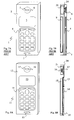
Fig. 7A a state of the art terminal much like the one inFig. 1 is shown from the front side. InFig. 7B the same terminal is schematically illustrated from the side in a sectional view with the front side facing left. In this drawing a number of elements normally included in a radio communication terminal are disclosed. It should be emphasised, though, that the dimensions are merely exemplary to illustrate the contribution and advantage of certain features of this embodiment of the invention. Furthermore, connections between the different elements of the terminal are not shown. Aground plane 24 is arranged in the terminal extending longitudinally through a part, or substantially the entire body, of the terminal. Normally, this ground plane is a layer of a printed circuit boards carrying the electronics of the terminal. Aspeaker 6 is placed at the front side of the terminal, over the ground plane as seen from the front side. The back of the speaker is coupled to thecavity 21, placed behind the ground plane, through an opening in the ground plane as illustrated in the drawing. The back wall ofcavity 21, i.e. the wall opposite to the ground plane, carries an antenna element, e.g. in the shape of a PIFA. A user interface comprises adisplay 3 and akey pad 4, and amicrophone 5 is placed at the bottom of the terminal. Abattery 9 is further included to supply the terminal electronics with electrical power. - In
Figs 8A and 8B an embodiment of the present invention is disclosed, in which thespeaker 16 is placed beside theuser interface 13, rather than under as in the embodiments ofFigs 2 ,4 ,5 and6 . In this embodiment there is no real sound channel, rather only an opening oroutlet 17. Thespeaker 16 is placed inside theantenna cavity 21, in order to benefit from the same space for acoustic purposes, as previously described. At the top portion of the terminal, i.e. the portion comprising the speaker and the antenna, the thickness of the terminal is in this embodiment basically defined by the distance between the antenna and the ground plane, since the thickness contribution from the speaker has been eliminated. Furthermore, even though theantenna cavity 21 has been partly occupied by the speaker, experimental laboratory tests on this design have surprisingly shown that the presence of the speaker will not result in reduced antenna performance if tuned properly. - The drawings of
Figs 7B and 8B indicate that the entire terminal can be made thinner by implementation of this embodiment. Naturally, this is dependent on the dimensions of the user interface, the battery, other electronics, and so on, and the arrangement of these elements. However,Fig. 8B further shows a feature relating to the ground plane. A first, upper, part of the ground plane defines the front face of the terminal, although it is preferably covered by a housing directly adjacent to theground plane 24. Since the user interface, e.g. thedisplay 13, has a certain thickness, the ground plane has a bent portion between the speaker and the user interface, wherein the ground plane first bends downwards towards the back side of the terminal, and then bends back towards the lower end carrying themicrophone 15. This way a second, lower, part of the ground plane is formed which extends in a plane closer to the back of the terminal than the first part. This makes room for thedisplay 13 and thekey pad 14 to be arranged over the ground plane, with their front sides substantially in the same plane as the top portion of the terminal, with thesound outlet 17 from the speaker. As is well known to the skilled person, the purpose of the antenna cavity is to place the antenna at a certain distance from the ground plane. For this reason it is likewise important in the present embodiment that the bent portion is not to close to the antenna, such that the uppermost edge of the lower part of the ground plane is located too close to the antenna. In other words, a certain minimum distance between the antenna and ground can be defined, and no part of the ground plane may be placed closer to the antenna than that. -
Chamber 21 acting as a cavity for both acoustic resonance and electromagnetic resonance may be a rectangular box, which makes it easy to seal by means ofgaskets 26. As mentioned before,antenna 29 may be a separate conductive element placed on the inside of theantenna lid 27 but may also be a conductive pattern coated on the inside oflid 27. - The present invention brings about several advantages, thanks to the inventive idea to mount the speaker inside the antenna cavity, where the antenna cavity is a sealed box. The front side of
speaker 16 is ported to theterminal front 20 by athin channel 22. By mounting thespeaker 16 in a sealedbox 21 it is possible to use asmaller speaker 16 than normal. This solution can also be used when thespeaker 16 performs in more than one mode. Consequently,speaker 16 can be used as a ringer in ringer mode, and also as a hands-free speaker in speakerphone mode. Porting the speaker to the front of the terminal by use of asound channel 22 makes it possible to reduce the length ofterminal 11 by five to ten millimetres and still keep the thickness at a minimum. Also the weight of the terminal 11 may be reduced due to the smaller terminal dimension. The antenna cavity ofchamber 21 is used to create a distance betweenantenna 29 and the ground plane ofPCB 24 in order to improve the bandwidth of the antenna, as is well known in the prior arts. Otherwise this cavity is normally not used for anything else. Furthermore, by placingspeaker 16 insidecavity 21, the function ofchamber 21 as an electromagnetic cavity will not be effected in any negative way, and will therefore not disturb the performance ofterminal 11. - The foregoing has described the principals, preferred embodiments and modes of operation of the present invention. However, the invention should not be construed as being limited to the particular embodiments discussed above. For example, it is well known in the state of the art to design mobile or cellular phones in a
foldable housing 12. Still, the desire to have small terminals is equally applicable to such a design, and so is the proposed solution of the present invention. Thus, the above described embodiments should be regarded as illustrative rather than restrictive, and it should be appreciated that variations may be made in those embodiments by those skilled in the arts without departing from the scope of the present invention as defined in the appended claims.
Claims (12)
- Communication terminal (11) comprising a housing (12), a user interface (13,14) on a front side (20) of the housing, said housing carrying therein a radio antenna element (27), a PCB (24) including a ground plane extending longitudinally through the terminal behind said user interface, a speaker (16), and a chamber (21) acting as an electromagnetic resonance cavity for the antenna and as an acoustic resonance cavity for the speaker, wherein said speaker is mounted inside said chamber, characterised in that said speaker is placed behind said PCB and completely behind said user interface as seen from said front side, wherein sound is coupled from the speaker to a front outlet (17) by means of an opening (28) formed in said PCB at the speaker, a sound channel (22) extending from said opening longitudinally in the terminal between said PCB and said user interface, past said speaker, to a bent portion (23) leading the sound channel around an edge of said user interface at an end portion of the terminal, from which bent portion the sound channel extends to the channel front outlet substantially perpendicular to said front side.
- The communication terminal as recited in claim 1, characterised in that said sound channel further has a channel top outlet (19) extending in a substantially longitudinal direction of the terminal at a top side of said housing.
- The communication terminal as recited in claim 1, characterised in that said user interface is a display (13).
- The communication terminal as recited in claim 1, characterised in that said user interface is a key pad (14).
- The communication terminal as recited in any of the previous claims, characterised in that said ground plane (24) defines a wall part of the chamber, through which wall part said sound channel outlet extends.
- The communication terminal as recited in any of the previous claims, characterised in that said chamber is sealed (26).
- The communication terminal as recited in any of the previous claims, characterised in that said chamber has a substantially rectangular box shape.
- The communication terminal as recited in any of the previous claims,
characterised in that said antenna element comprises a substantially flat pattern of conductive material on a wall (29) of said chamber. - The communication terminal as recited in any of the previous claims, characterised in that said speaker is devised to convey audio information such as speech to a terminal user.
- The communication terminal as recited in any of the previous claims, characterised in that said speaker is devised to act as a ringer by transmitting a predetermined sound signal to bring a user's attention to the terminal.
- The communication terminal as recited in any of the claims 1 - 9, characterised in that said speaker comprises a buzzer devised to act as a ringer by transmitting a predetermined sound signal to bring a user's attention to the terminal.
- The communication terminal as recited in any of the claims 1 - 9, characterised in that said speaker is a multi mode actuator devised to act as a ringer and as a vibrator by transmitting predetermined sound signals or vibrations to bring a user's attention to the terminal.
Priority Applications (10)
| Application Number | Priority Date | Filing Date | Title |
|---|---|---|---|
| EP02077565A EP1379101B1 (en) | 2002-07-01 | 2002-07-01 | Speaker arrangement for communication terminal |
| DE60234327T DE60234327D1 (en) | 2002-07-01 | 2002-07-01 | Speaker arrangement for communication terminal |
| AT02077565T ATE448646T1 (en) | 2002-07-01 | 2002-07-01 | SPEAKER ARRANGEMENT FOR COMMUNICATIONS TERMINAL |
| TW092116865A TWI267315B (en) | 2002-07-01 | 2003-06-20 | Communication terminal |
| CN03815899XA CN1666565B (en) | 2002-07-01 | 2003-06-26 | Speaker arrangement for communication terminal |
| KR1020047020423A KR101013330B1 (en) | 2002-07-01 | 2003-06-26 | Speaker arrangement for communication terminal |
| JP2004516683A JP4430533B2 (en) | 2002-07-01 | 2003-06-26 | Speaker placement for communication terminals |
| AU2003242758A AU2003242758A1 (en) | 2002-07-01 | 2003-06-26 | Speaker arrangement for communication terminal |
| US10/519,822 US7233678B2 (en) | 2002-07-01 | 2003-06-26 | Speaker arrangement for communication terminal |
| PCT/EP2003/006724 WO2004004408A1 (en) | 2002-07-01 | 2003-06-26 | Speaker arrangement for communication terminal |
Applications Claiming Priority (1)
| Application Number | Priority Date | Filing Date | Title |
|---|---|---|---|
| EP02077565A EP1379101B1 (en) | 2002-07-01 | 2002-07-01 | Speaker arrangement for communication terminal |
Publications (2)
| Publication Number | Publication Date |
|---|---|
| EP1379101A1 EP1379101A1 (en) | 2004-01-07 |
| EP1379101B1 true EP1379101B1 (en) | 2009-11-11 |
Family
ID=29719741
Family Applications (1)
| Application Number | Title | Priority Date | Filing Date |
|---|---|---|---|
| EP02077565A Expired - Lifetime EP1379101B1 (en) | 2002-07-01 | 2002-07-01 | Speaker arrangement for communication terminal |
Country Status (3)
| Country | Link |
|---|---|
| EP (1) | EP1379101B1 (en) |
| AT (1) | ATE448646T1 (en) |
| DE (1) | DE60234327D1 (en) |
Cited By (2)
| Publication number | Priority date | Publication date | Assignee | Title |
|---|---|---|---|---|
| WO2023018166A1 (en) * | 2021-08-10 | 2023-02-16 | 삼성전자 주식회사 | Electronic device comprising speaker module |
| WO2023018170A1 (en) * | 2021-08-10 | 2023-02-16 | 삼성전자 주식회사 | Electronic device comprising speaker module and receiver module |
Families Citing this family (10)
| Publication number | Priority date | Publication date | Assignee | Title |
|---|---|---|---|---|
| FR2864415A1 (en) * | 2003-12-23 | 2005-06-24 | Cit Alcatel | Device e.g. radiotelephonic terminal, has rear acoustic cavity lined by lower side of printed circuit and rear side of case, and by upper edge of case and partition, where partition extends between lower and rear sides |
| US7565949B2 (en) * | 2005-09-27 | 2009-07-28 | Casio Computer Co., Ltd. | Flat panel display module having speaker function |
| KR101991504B1 (en) * | 2012-02-24 | 2019-09-30 | 삼성전자주식회사 | Speaker module and portable terminal having duct |
| TW201349829A (en) * | 2012-05-24 | 2013-12-01 | Acer Inc | Receiving device |
| CN103458078A (en) * | 2012-06-05 | 2013-12-18 | 宏碁股份有限公司 | Telephone receiver device |
| US10261167B2 (en) | 2014-09-22 | 2019-04-16 | Symbol Technologies, Llc | Co-located locationing technologies |
| CN107613441A (en) * | 2017-10-31 | 2018-01-19 | 珠海市魅族科技有限公司 | Terminal device |
| CN108321487A (en) * | 2018-01-26 | 2018-07-24 | 宇龙计算机通信科技(深圳)有限公司 | A kind of communication terminal |
| CN109274790A (en) * | 2018-09-27 | 2019-01-25 | 维沃移动通信有限公司 | A kind of mobile terminal |
| KR102651992B1 (en) | 2019-07-02 | 2024-03-27 | 삼성전자주식회사 | Electronic device including acoustic module |
Family Cites Families (5)
| Publication number | Priority date | Publication date | Assignee | Title |
|---|---|---|---|---|
| GB2310559B (en) * | 1996-02-23 | 2000-09-20 | Nokia Mobile Phones Ltd | Audio output apparatus for a mobile communication device |
| SE522176C2 (en) * | 1999-05-18 | 2004-01-20 | Ericsson Telefon Ab L M | Speaker device with resonant chamber |
| JP2001016674A (en) * | 1999-06-28 | 2001-01-19 | Marantz Japan Inc | Device with built-in speaker |
| FI115341B (en) * | 2000-08-29 | 2005-04-15 | Nokia Corp | Mobile station and antenna arrangement for a mobile station |
| DE10052909A1 (en) * | 2000-10-25 | 2002-05-08 | Siemens Ag | communication terminal |
-
2002
- 2002-07-01 DE DE60234327T patent/DE60234327D1/en not_active Expired - Lifetime
- 2002-07-01 AT AT02077565T patent/ATE448646T1/en not_active IP Right Cessation
- 2002-07-01 EP EP02077565A patent/EP1379101B1/en not_active Expired - Lifetime
Cited By (2)
| Publication number | Priority date | Publication date | Assignee | Title |
|---|---|---|---|---|
| WO2023018166A1 (en) * | 2021-08-10 | 2023-02-16 | 삼성전자 주식회사 | Electronic device comprising speaker module |
| WO2023018170A1 (en) * | 2021-08-10 | 2023-02-16 | 삼성전자 주식회사 | Electronic device comprising speaker module and receiver module |
Also Published As
| Publication number | Publication date |
|---|---|
| DE60234327D1 (en) | 2009-12-24 |
| EP1379101A1 (en) | 2004-01-07 |
| ATE448646T1 (en) | 2009-11-15 |
Similar Documents
| Publication | Publication Date | Title |
|---|---|---|
| US7233678B2 (en) | Speaker arrangement for communication terminal | |
| US8005207B2 (en) | Microphone coupler system for a communication device | |
| US7107016B2 (en) | Component for a wireless communication terminal constituting an antenna, loudspeaker and ringer | |
| US7750854B2 (en) | Combined speaker and antenna component | |
| EP1379101B1 (en) | Speaker arrangement for communication terminal | |
| CN109076122B (en) | Sliding closure formula terminal | |
| US7460074B2 (en) | Communication terminals having integrated antenna and speaker assemblies | |
| JP2005286874A (en) | Electronic communication device | |
| EP1445823B1 (en) | Combined speaker and antenna component | |
| EP1489681A1 (en) | Integrated antenna and speaker | |
| KR20080100207A (en) | Portable wireless device | |
| JP4571632B2 (en) | Speaker placement for foldable terminals | |
| EP1780989B1 (en) | Microphone coupler for a communication device | |
| EP1496676B1 (en) | Speaker arrangement for foldable terminals | |
| EP1558008B1 (en) | Portable communication device equipped with two flat panel speakers | |
| JP4926921B2 (en) | Portable wireless device | |
| KR20050019719A (en) | Compact and space-saving audio device |
Legal Events
| Date | Code | Title | Description |
|---|---|---|---|
| PUAI | Public reference made under article 153(3) epc to a published international application that has entered the european phase |
Free format text: ORIGINAL CODE: 0009012 |
|
| AK | Designated contracting states |
Kind code of ref document: A1 Designated state(s): AT BE BG CH CY CZ DE DK EE ES FI FR GB GR IE IT LI LU MC NL PT SE SK TR |
|
| AX | Request for extension of the european patent |
Extension state: AL LT LV MK RO SI |
|
| 17P | Request for examination filed |
Effective date: 20040122 |
|
| AKX | Designation fees paid |
Designated state(s): AT BE BG CH CY CZ DE DK EE ES FI FR GB GR IE IT LI LU MC NL PT SE SK TR |
|
| 17Q | First examination report despatched |
Effective date: 20080414 |
|
| GRAP | Despatch of communication of intention to grant a patent |
Free format text: ORIGINAL CODE: EPIDOSNIGR1 |
|
| GRAS | Grant fee paid |
Free format text: ORIGINAL CODE: EPIDOSNIGR3 |
|
| GRAA | (expected) grant |
Free format text: ORIGINAL CODE: 0009210 |
|
| AK | Designated contracting states |
Kind code of ref document: B1 Designated state(s): AT BE BG CH CY CZ DE DK EE ES FI FR GB GR IE IT LI LU MC NL PT SE SK TR |
|
| REG | Reference to a national code |
Ref country code: GB Ref legal event code: FG4D |
|
| REG | Reference to a national code |
Ref country code: CH Ref legal event code: EP |
|
| REG | Reference to a national code |
Ref country code: IE Ref legal event code: FG4D |
|
| REF | Corresponds to: |
Ref document number: 60234327 Country of ref document: DE Date of ref document: 20091224 Kind code of ref document: P |
|
| NLV1 | Nl: lapsed or annulled due to failure to fulfill the requirements of art. 29p and 29m of the patents act | ||
| PG25 | Lapsed in a contracting state [announced via postgrant information from national office to epo] |
Ref country code: FI Free format text: LAPSE BECAUSE OF FAILURE TO SUBMIT A TRANSLATION OF THE DESCRIPTION OR TO PAY THE FEE WITHIN THE PRESCRIBED TIME-LIMIT Effective date: 20091111 Ref country code: ES Free format text: LAPSE BECAUSE OF FAILURE TO SUBMIT A TRANSLATION OF THE DESCRIPTION OR TO PAY THE FEE WITHIN THE PRESCRIBED TIME-LIMIT Effective date: 20100222 Ref country code: SE Free format text: LAPSE BECAUSE OF FAILURE TO SUBMIT A TRANSLATION OF THE DESCRIPTION OR TO PAY THE FEE WITHIN THE PRESCRIBED TIME-LIMIT Effective date: 20091111 Ref country code: PT Free format text: LAPSE BECAUSE OF FAILURE TO SUBMIT A TRANSLATION OF THE DESCRIPTION OR TO PAY THE FEE WITHIN THE PRESCRIBED TIME-LIMIT Effective date: 20100311 |
|
| PG25 | Lapsed in a contracting state [announced via postgrant information from national office to epo] |
Ref country code: CY Free format text: LAPSE BECAUSE OF FAILURE TO SUBMIT A TRANSLATION OF THE DESCRIPTION OR TO PAY THE FEE WITHIN THE PRESCRIBED TIME-LIMIT Effective date: 20091111 |
|
| PG25 | Lapsed in a contracting state [announced via postgrant information from national office to epo] |
Ref country code: BE Free format text: LAPSE BECAUSE OF FAILURE TO SUBMIT A TRANSLATION OF THE DESCRIPTION OR TO PAY THE FEE WITHIN THE PRESCRIBED TIME-LIMIT Effective date: 20091111 Ref country code: AT Free format text: LAPSE BECAUSE OF FAILURE TO SUBMIT A TRANSLATION OF THE DESCRIPTION OR TO PAY THE FEE WITHIN THE PRESCRIBED TIME-LIMIT Effective date: 20091111 |
|
| PG25 | Lapsed in a contracting state [announced via postgrant information from national office to epo] |
Ref country code: EE Free format text: LAPSE BECAUSE OF FAILURE TO SUBMIT A TRANSLATION OF THE DESCRIPTION OR TO PAY THE FEE WITHIN THE PRESCRIBED TIME-LIMIT Effective date: 20091111 Ref country code: DK Free format text: LAPSE BECAUSE OF FAILURE TO SUBMIT A TRANSLATION OF THE DESCRIPTION OR TO PAY THE FEE WITHIN THE PRESCRIBED TIME-LIMIT Effective date: 20091111 Ref country code: BG Free format text: LAPSE BECAUSE OF FAILURE TO SUBMIT A TRANSLATION OF THE DESCRIPTION OR TO PAY THE FEE WITHIN THE PRESCRIBED TIME-LIMIT Effective date: 20100211 |
|
| PG25 | Lapsed in a contracting state [announced via postgrant information from national office to epo] |
Ref country code: CZ Free format text: LAPSE BECAUSE OF FAILURE TO SUBMIT A TRANSLATION OF THE DESCRIPTION OR TO PAY THE FEE WITHIN THE PRESCRIBED TIME-LIMIT Effective date: 20091111 Ref country code: SK Free format text: LAPSE BECAUSE OF FAILURE TO SUBMIT A TRANSLATION OF THE DESCRIPTION OR TO PAY THE FEE WITHIN THE PRESCRIBED TIME-LIMIT Effective date: 20091111 |
|
| PLBE | No opposition filed within time limit |
Free format text: ORIGINAL CODE: 0009261 |
|
| STAA | Information on the status of an ep patent application or granted ep patent |
Free format text: STATUS: NO OPPOSITION FILED WITHIN TIME LIMIT |
|
| 26N | No opposition filed |
Effective date: 20100812 |
|
| PG25 | Lapsed in a contracting state [announced via postgrant information from national office to epo] |
Ref country code: GR Free format text: LAPSE BECAUSE OF FAILURE TO SUBMIT A TRANSLATION OF THE DESCRIPTION OR TO PAY THE FEE WITHIN THE PRESCRIBED TIME-LIMIT Effective date: 20100212 |
|
| PG25 | Lapsed in a contracting state [announced via postgrant information from national office to epo] |
Ref country code: MC Free format text: LAPSE BECAUSE OF NON-PAYMENT OF DUE FEES Effective date: 20100731 |
|
| REG | Reference to a national code |
Ref country code: CH Ref legal event code: PL |
|
| PG25 | Lapsed in a contracting state [announced via postgrant information from national office to epo] |
Ref country code: IT Free format text: LAPSE BECAUSE OF FAILURE TO SUBMIT A TRANSLATION OF THE DESCRIPTION OR TO PAY THE FEE WITHIN THE PRESCRIBED TIME-LIMIT Effective date: 20091111 |
|
| PG25 | Lapsed in a contracting state [announced via postgrant information from national office to epo] |
Ref country code: CH Free format text: LAPSE BECAUSE OF NON-PAYMENT OF DUE FEES Effective date: 20100731 Ref country code: LI Free format text: LAPSE BECAUSE OF NON-PAYMENT OF DUE FEES Effective date: 20100731 |
|
| PG25 | Lapsed in a contracting state [announced via postgrant information from national office to epo] |
Ref country code: IE Free format text: LAPSE BECAUSE OF NON-PAYMENT OF DUE FEES Effective date: 20100701 |
|
| PG25 | Lapsed in a contracting state [announced via postgrant information from national office to epo] |
Ref country code: LU Free format text: LAPSE BECAUSE OF NON-PAYMENT OF DUE FEES Effective date: 20100701 Ref country code: NL Free format text: LAPSE BECAUSE OF FAILURE TO SUBMIT A TRANSLATION OF THE DESCRIPTION OR TO PAY THE FEE WITHIN THE PRESCRIBED TIME-LIMIT Effective date: 20091111 |
|
| PG25 | Lapsed in a contracting state [announced via postgrant information from national office to epo] |
Ref country code: TR Free format text: LAPSE BECAUSE OF FAILURE TO SUBMIT A TRANSLATION OF THE DESCRIPTION OR TO PAY THE FEE WITHIN THE PRESCRIBED TIME-LIMIT Effective date: 20091111 |
|
| REG | Reference to a national code |
Ref country code: FR Ref legal event code: PLFP Year of fee payment: 15 |
|
| REG | Reference to a national code |
Ref country code: FR Ref legal event code: PLFP Year of fee payment: 16 |
|
| PGFP | Annual fee paid to national office [announced via postgrant information from national office to epo] |
Ref country code: FR Payment date: 20170613 Year of fee payment: 16 Ref country code: GB Payment date: 20170628 Year of fee payment: 16 |
|
| PGFP | Annual fee paid to national office [announced via postgrant information from national office to epo] |
Ref country code: DE Payment date: 20170627 Year of fee payment: 16 |
|
| REG | Reference to a national code |
Ref country code: DE Ref legal event code: R119 Ref document number: 60234327 Country of ref document: DE |
|
| GBPC | Gb: european patent ceased through non-payment of renewal fee |
Effective date: 20180701 |
|
| PG25 | Lapsed in a contracting state [announced via postgrant information from national office to epo] |
Ref country code: DE Free format text: LAPSE BECAUSE OF NON-PAYMENT OF DUE FEES Effective date: 20190201 Ref country code: GB Free format text: LAPSE BECAUSE OF NON-PAYMENT OF DUE FEES Effective date: 20180701 Ref country code: FR Free format text: LAPSE BECAUSE OF NON-PAYMENT OF DUE FEES Effective date: 20180731 |