BACKGROUND OF THE INVENTION
Field of the Invention
The present invention relates to an optical disk
high-speed replaying/recording apparatus which replays an optical
disk at a speed higher than a normal replay speed for reading data
recorded on the optical disk, and records the read data on a
writable/rewritable optical disk. More specifically, the present
invention relates to a high-speed replaying/recording apparatus
which replays an optical disk at a replay speed suitable for the
optical disk.
Description of the Background Art
In recent years, there have been developments of optical
disk high-speed replaying/recording apparatuses capable of
reproducing data recorded on various types of optical disks
typified by CDs and DVDs at a speed higher than the original replay
speed and, also recording the reproduced data on another
writable/rewritable optical disk.
The operation of a typical example of the optical disk
high-speed replaying/recording apparatuses in which a CD is used
as a recording source optical disk and an MD is used as a
writable/rewritable optical disk is briefly described below. The
CD having recorded thereon music or non-music data is rotated at
a speed higher than the normal replay speed. The recorded data
is then read in units smaller than tracks. The read data is then
written in the MD in predetermined recording units (data blocks
smaller than reading units or tracks, or CDs).
Management information regarding this written data is
written in a UTOC (User Table of Content) area of the MD, thereby
achieving completion of recording of the data reproduced from the
CD onto the MD. The management information written in this UTOC
area is hereinafter referred to as UTOC information. The UTOC
information can be written/rewritten by users in the UTOC area
in accordance with the data writing state. On the other hand,
as is well known, TOC (Table of Content) information cannot be
arbitrarily written or rewritten by users in a TOC area provided
on a read-only optical disk, such as a CD.
In the optical disk high-speed replaying/recording
apparatus, data is read from a recording source optical disk (CD)
by rotating the disk at a high speed obtained by increasing a normal
replay speed several-fold. Therefore, in some cases, the recorded
data cannot be correctly read from the CD due to replay inhibiting
factors negligible at normal replay, such as, firstly, surface
flaws or deformation of the CD; secondly, insertion accuracy;
thirdly, circuit noise; and lastly combinations of those.
Consequently, data cannot be correctly recorded in the MD. In
such cases, even though the user desires high-speed
replaying/recording, the replay speed has to be reduced to a speed
at which data can be correctly read from the CD in order to record
the data on the writable/rewritable optical disk.
That is , of the above replay inhibiting factors , physical
defectives of the medium, such as surface flaws or deformation
of the CD, are not influenced by the replay speed itself. However,
as the rotational speed, that is, the replay speed, of the CD is
lower, the degree of inhibition regarding optical reading by an
optical pickup is lower, and therefore data reading is improved
more. Also, positional accuracy, such as accuracy of insertion
of the CD in the CD drive, is not influenced by the replay speed
itself. However, as the rotational speed of the CD is lower, the
degree of changes in positional relation between the optical pickup
and a pit caused by errors in positional accuracy is lower, and
therefore data reading is improved more. Furthermore, electrical
inhibiting factors, such as circuit noise, are basically not
influenced by the rotational speed of the CD, but are influenced
by the replay speed as electrical processing. That is, as the
replay speed is lower, influences of noise are smaller, and
therefore data reproduction is improved more.
In the above various replay inhibiting factors, the
inability to normally reproduce the recorded data from the CD at
high speed replay is a direct reason for the inability to normally
record the data on the MD. Therefore, whatever the true reason
for trouble in data reproduction is, the optical disk high-speed
replaying/recording apparatus is structured so as to take a measure
of reducing the rotational speed, that is, the replay speed, of
the CD for a recovery to normal reproduction of the recorded data,
and then recording the reproduced data on the MD.
The CD, which is an example of the above-described
recording source optical disk, is under CLV (Constant Linear
Velocity) control so that the linear velocity is constant. That
is, when a read position is at the inner rim side, the rotational
speed is higher compared with a case where the read position is
at the outer rim side. Also, depending on the types of the optical
disks other than the CD, various rotation control schemes are used,
such as a CAV (Constant Angular Velocity) scheme, a ZCAV (Zone
Constant Angular Velocity) scheme, and a ZCLV (Zone Constant Linear
Velocity) scheme. Therefore, the replay speed and the rotational
speed of the optical disk do not have a fixed relation. Rather,
depending on the read/replay position of the optical disk, the
optical disk can be rotated at a different speed even with the
same replay speed. However, the above control schemes are similar
to each other in that the optical disk high-speed
replaying/recording apparatus is structured to reduce the replay
speed (rotational speed) when reading cannot be made, thereby
waiting until reading of the recorded data is improved.
As described above, in the optical disk high-speed
replaying/recording apparatus, depending on the read/replay
position, the rotational speed of the optical disk is varied even
with the same replay speed. Therefore, influences of the above
three replay inhibiting factors are varied depending on the
read/replay position. For example, consider a case where there
is a data reproduction factor of a uniform size in the radial
direction of the optical disk. In this case, when high-speed
replaying/recording is performed at a constant replay speed, data
reproduction can be successfully made in the outer rim, but can
be failed in the inner rim, or vice versa. Furthermore, the replay
inhibiting factor can be varied in size, and also can be located
in various places. Therefore, a sudden halt to replay or a sudden
start of replay can occur during high-speed replaying/recording.
In the optical disk high-speed replaying/recording
apparatus, every time the recorded data is read and reproduced
from the CD, the data is actually recorded on the MD in sequence,
and its UTOC information is written in units of tracks or CDs,
thereby completing recording on the MD. Therefore, if
reproduction defects occur in the course of recording data on the
MD, depending on the timing of writing the UTOC information,
defective data may be recorded on the MD at least in units of tracks
or CDs. In that case, inconveniences may occur depending on the
type of the recorded defective data or the location of the defective
data, such as that the data which has been read from the CD and
then recorded on the MD cannot be read in units of tracks or CDs.
In order to prevent such inconveniences, the following
measure is required. That is, when replay abnormality occurs at
a read position, the replay speed is reduced stepwise to an
appropriate replay speed which allows normal replay at that read
position, and then data reproduction is restarted at the reduced
high-speed replay speed. The replay speed at the time of restarting
high-speed replaying/recording is obtained by reducing a
predetermined speed from the original replay speed at the time
of starting high-speed replaying/recording. In this sense, the
replay speed at the time of restarting is hereinafter referred
to as a reduced replay speed.
However, the read data units to be reproduced at the
newly-found appropriate reduced replay speed from the read position
where replay abnormality occurred are different in replaying and
recording conditions from other data units that have been already
read and recorded on the MD. Therefore, consistency in the recoded
data will be disadvantageously lost. In order to prevent such
disadvantages, a read position from which data reproduction is
restarted at the reduced replay speed has to be back by a
predetermined number of read data units from the position where
replay abnormality occurred.
That is, it is practically meaningless to record each
read data unit alone on the MD for reproduction. Instead, by
recording a plurality of read data units on the MD in accordance
to predetermined rules, a meaningful piece of record data unit
is formed on the MD, and is utilized by users. In one example
where the CD contains music tracks, a predetermined number of read
data units are sequentially recorded on the MD in accordance with
predetermined rules, thereby completing a piece of track data
corresponding to one track. In another example where the CD
contains computer data, a predetermined number of read data units
are sequentially recorded on the MD in accordance with
predetermined rules, thereby completing a piece of sector data.
A collection of such pieces of sector data forms a file.
However, the read data units to be reproduced at the
newly-found appropriate reduced replay speed from the read position
where replay abnormality occurred are different in replaying and
recording conditions from other data units that have been already
read and recorded on the MD. Therefore, consistency in the recoded
data will be disadvantageously lost. Consequently, further
recording such read data units of inconsistency to form a piece
of track data on the MD cannot make it possible to reproduce correct
information from the track data.
In order to prevent such inconsistency in the record
data units, reproducing is restarted at the reduced replay speed
by going back to the read start position of the recorded data unit
(track, file) to which the read data unit having reproduction
defects belongs. That is, the read data unit that has been already
reproduced at the original high-speed replay speed has to be
redundantly reproduced under different conditions.
However, as described above, the replay inhibiting
factor can be varied in size, and also can be located in various
places. Therefore, a sudden halt to replay or a sudden start of
replay can occur at high-speed replaying/recording. In other
words , even when high-speed replay is started at a newly-set reduced
replay speed, defects may occur before the completion of
reproduction of the entire record units after merely several read
data units are reproduced from the read position where reproduction
defects occurred.
As such, frequent occurrences of read defects even at
the reduced replay speed would increase useless work loads of
redundantly reproducing the already-reproduced data unit. These
increased work loads significantly impair the high-speed
replaying/recoding function, at which the optical disk high-speed
replaying/recording apparatus is originally aimed. In worst
cases, it takes more time compared with a case of
replaying/recording the CD at its original normal speed.
SUMMARY OF THE INVENTION
Therefore, an object of the present invention is to
provide an optical disk high-speed replaying/recording apparatus
which reads and reproduces data recorded on an optical disk at
a speed higher than the normal replay speed of the optical disk,
and records the reproduced data on a writable/rewritable optical
disk except defective data caused by reproduction defects.
The present invention has the following features to
attain the object mentioned above.
An aspect of the present invention is directed to an
optical disk high-speed replaying/recording apparatus which reads,
from a first optical disk having recorded thereon digital data
in first units to be reproduced at a first replay speed as being
a normal replay speed, the digital data in second units smaller
than the first units at a second replay speed higher than the first
replay speed, writes the read second units of digital data in
a writable second optical disk, and then records the first units
in the second optical disk, the apparatus including:
These and other objects, features, aspects and
advantages of the present invention will become more apparent from
the following detailed description of the present invention when
taken in conjunction with the accompanying drawings.
BRIEF DESCRIPTION OF THE DRAWINGS
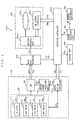
FIG. 1 is a block diagram illustrating the configuration
of an optical disk high-speed replaying/recording apparatus
according to a first embodiment of the present invention;
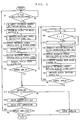
FIG. 2 is a flow chart showing the operation of the optical
disk high-speed replaying/recording apparatus illustrated in
FIG. 1;
FIG. 3 is a block diagram illustrating the configuration
of an optical disk high-speed replaying/recording apparatus
according to a second embodiment of the present invention;
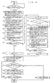
FIG. 4 is a flow chart showing the operation of the optical
disk high-speed replaying/recording apparatus illustrated in
FIG. 3;
FIG. 5 is an illustration for describing an example of
a relation between an unstable high-speed replay area and an
outer-rim stable high-speed replay area in an optical disk of CLV
scheme;
FIG. 6 is an illustration for describing an example of
a relation between an unstable high-speed replay area and an
inner-rim stable high-speed replay area in an optical disk of CAV
scheme;
FIG. 7 is an illustration for describing an example of
a relation among an inner-rim stable high-speed replay area, an
unstable high-speed replay area, and an outer-rimstable high-speed
replay area in an optical disk of ZCLV scheme; and
FIG. 8 is an illustration for describing an example of
a relation among an inner-rim stable high-speed replay area, an
unstable high-speed replay area, and an outer-rimstablehigh-speed
replay area in an optical disk of ZCAV scheme.
DESCRIPTION OF THE PREFERRED EMBODIMENTS
(First embodiment)
With reference to FIGS. 1 and 2, an optical disk
high-speed replaying/recording apparatus according to a first
embodiment of the present invention is described below. As
illustrated in FIG. 1, an optical disk high-speed
replaying/recording apparatus HSC1 broadly includes a combination
drive 130, a read data detector 200, an MD drive 230, an operation
controller 300a, and a display unit 400. Also, the optical disk
high-speed replaying/recording apparatus HSC1 includes a read
signal processing unit for performing various processes on signals
read from the combination drive 130 and the MD drive 230 to generate
audio signals, video, or computer data for output to a loudspeaker,
a monitor, or another recording apparatus. However, such a read
signal processing unit is not a feature of the present invention,
and therefore is not described herein or illustrated in the
drawings.
The display unit 400 is preferably structured by a
light-emitting means, such as a vacuum fluorescent display, for
optically presenting information, such as an operation mode of
the optical disk high-speed replaying/recording apparatus HSC1
to users. The operation controller 300a is connected to the
combination drive 130, the MD drive 230, the above-mentioned read
signal processing unit (not shown), and the display unit 400 so
as to control the entire operation of the optical disk high-speed
replaying/recording apparatus HSC1.
The combination drive 130 includes at least one optical
disk drive 132, a drive system controller 134, a replay speed
switching unit 136, and an optical disk controller (denoted as
"ODC" in FIG. 1) 138. In the optical disk drive 132 , various types
of optical disk media can be inserted. With an optical medium
being inserted, the optical disk drive 132 reads recoded data
therefrom for output to the optical disk controller 138. The
optical disk drive 132 includes a means for detecting the type
of the inserted optical disk. Based on the detection results,
the inserted optical disk is recognized as being for an optical
disk drive corresponding to the detected type of the optical disk.
In this specification, for convenience in description, different
drives are used for different optical disks. That is, the optical
disk drive 132 includes optical disk players typified by a CD
drive 132_1, a DVD drive 132_2, a VCD drive 132_3, and an MP3
drive 132_4.
The CD drive 132_1 reads music data or digital data
typified by computer programs from the inserted CD for output as
CD data Scd. The DVD drive 132_2 reproduces MPEG data Sdv from
a DVD for output. The VCD drive 132_3 reproduces an audio signal
from a video CD for output as a video CD audio signal Svd. The
MP3 drive 132_4 reproduces audio data from an MP3 file recorded
on the optical disk for output as an MP3 audio signal Smp. The
drive system controller 134 is connected to the optical disk
drive 132 for mutually exchanging a combination drive control
signal SCc, controlling the operation of the optical disk drive 132,
and further detecting the type of the optical disk inserted in
the optical disk drive 132.
The MD drive 230 includes an MD system controller 230_1
andawriting/readingunit 230_3. The MD drive 230 further includes
a means for driving an MD and other related components. These
means and components are, however, not a feature of the present
invention, and therefore are not described herein. The MD
drive 230 writes, in the MD, the CD data Scd that has been read
from the CD, reproduced, and then supplied by the combination
drive 130 through the read data detector 200, or reads data written
in the MD. The MD system controller 230_1 controls writing/reading
performed by the writing/reading unit 230_3 on a
writable/rewritable optical disk 230_5. This control is based
on an MD drive state signal SMm and a combination drive state
signal SMc.
The operation controller 300a preferably includes a
light-receiving unit 320 and a remote controller 330. The user
operates the remote controller 330 to give an instruction to the
optical disk high-speed replaying/recording apparatus HSC1. That
is, the remote controller 330 emits a remote control signal SR
in accordance with user's operations. The light-receiving
unit 320 receives the remote control signal SR emitted from the
remote controller 330 to output a user operation signal SU
reflecting the user's operational intention to the operation
controller 300a.
Based on the user instruction signal SU supplied by the
light-receiving unit 320, the operation controller 330a generates
a combination drive control signal SOc for controlling the
operation of the combination drive 130 for output to the drive
system controller 134. Based on the combination drive control
signal SOc, the drive system controller 134 generates acombination
drive control signal SCc for controlling the optical disk drive 132 .
The drive system controller 134, on the other hand, generates a
combination drive state signal SMc including medium identification
information representing the type of the optical disk inserted
in the optical disk drive 132 and information about the state of
operation of the combination drive 130, and then outputs the
generated signal to the operation controller 300a.
Based on the user instruction signal SU, the combination
drive state signal SMc, a reading/reproducing state signal Sjr,
and the MD drive state signal SMm, the operation controller 300a
generates an MD control signal SCm for controlling the operation
of the MD drive 230 for output to the MD drive 230.
In the present embodiment, the optical disk high-speed
replaying/recording apparatus HSC1 preferably uses a CD as a
recording source optical disk and an MD (writable/rewritable
optical disk 230_5) as a recording destination optical disk, as
with Background Art. Therefore, the drive system controller 134
generates a rotational speed instruction signal Srn indicative
of a rotational speed corresponding to the replay speed designated
by the combination drive control signal SCc supplied by the
operation controller 300a, and then outputs the generated
signal Srn to the replay speed switching unit 136. In accordance
with the type of the rotation control scheme (ZCAV, ZCLV, or CAV),
the drive system controller 134 generates a rotational speed
instruction signal Srn for rotation at the replay speed designated
by the user.
Based on the rotational speed instruction signal Srn,
the replay speed switching unit 136 causes the CD drive 132_1 to
perform rotation at a speed corresponding to the replay speed
designated by the user. That is, the rotational speed is changed
depending on a position in the diameter direction so that a linear
velocity, which represents a speed of reading data, at a read
position is equal to the replay speed designated by the user. The
replay speed switching unit 136 generates a reading speed
signal Srs indicative of a speed of reading data from the CD, and
then outputs the generated signal Srs to the optical disk
controller 138.
Based on the reading speed signal Srs, the optical disk
controller 138 retrieves, from the CD data Scd supplied by the
CD drive 132_1, audio data (or computer content data) Sad and a
sub code Ssb for output to the read data detector 200. Note that,
although the data output from the optical disk controller 138 varies
depending on the type of the recording source optical disk, what
is basically output is content data and management data
corresponding to the audio data Sad and the sub code Ssb,
respectively, in the case of a CD. In this sense, the audio data Sad
and the sub code Ssb retrieved from the CD data Scd are hereinafter
referred to as content data Sad and content management data Ssb,
respectively, as required.
Based on the content data Sad and the content management
data Ssb, the read data detector 200 generates a replay state
signal Sjr indicative of whether reading/reproducing of the data
from the CD is normally performed, and then outputs the generated
signal Sjr to the operation controller 300a.
Based on the user instruction signal SU, the operation
controller 300a further replays the CD inserted in the CD
drive 132_1 at an N-fold normal replay speed (N is an arbitrary
positive number) so as to cause the reproduced data to be recorded
on the MD. Also, based on the above-described user instruction
signal SU, the combination drive state signal SMc, and the MD drive
state signal SMm, the operation controller 300a generates an
operation state display signal SOd indicative of the state of
operation of the optical disk high-speed replaying/recording
apparatus HSC1, and then outputs the generated signal SOd to the
display unit 400. Based on the operation state display signal SOd,
the display unit 400 uses an optical display technique to present
to the user the state of operation of the optical disk high-speed
replaying/recording apparatus HSC1.
With reference to the flow chart illustrated in FIG. 2,
only the optical disk high-speed replaying/recording procedure
performed by the optical disk high-speed replaying/recording
apparatus HSC1 is described. When the optical disk high-speed
replaying/recording apparatus HSC1 is powered ON to start the
operation, the operation controller 300a first determines in
step S2 based on the user instruction signal SU whether an
instruction has been given for high-speed replaying/recording of
the optical disk. If it is determined as No, the process of this
step is repeated until it is determined as Yes. The control
procedure then goes to the next step S4.
In step S4, based on the user instruction signal SU,
the operation controller 300a determines a recording source optical
disk and recording destination optical disk. As described above,
whether a recording source optical disk (CD) and an MD (recording
destination optical disk) have been inserted in the combination
drive 130 and the MD drive 230 is automatically detected. Therefore,
if no recording source optical disk (CD) or no recording destination
optical disk (MD) has been inserted, the user cannot select
high-speed recording. For this reason, in this step S4, the
recording source optical disk and the recording destination optical
disk are always determined. In the present example, the inserted
CD and the inserted MD are determined and recognized as the recording
source optical disk and the recording destination optical disk,
respectively. The control procedure then goes to the next step
S6.
In step S6, based on the user instruction signal SU,
the operation controller 300a detects a high-speed replay
multiple N, which defines by how much the normal replay speed of
the recording source optical disk is multiplied. That is, in the
present example, it is determined by how much the normal speed
of the CD is multiplied for recording data on the MD. The high-speed
replay multiple N determined in this step is supplied as a
combination drive control signal SOc to the drive system
controller 134. The control procedure then goes to the next
step S8.
In step S8, based on the high-speed replay multiple N,
the drive system controller 134 determines the number of rotations
of the recording source optical disk to generate a rotational speed
instruction signal Srn for output to the replay speed switching
unit 136. As described above, depending on the type of the optical
disk and the scheme for controlling the rotation of the optical
disk, the number of rotations (angular velocity) defined by the
rotational speed instruction signal Srn is not necessarily constant
with respect to the same replay speed. Therefore, needless to
say, the N-fold replay speed is not necessarily equal to the N-fold
angular velocity. The control procedure then goes to the next
step S10.
In step S10, based on the rotational speed instruction
signal Srn, the replay speed switching unit 136 rotates the
recording source optical disk (CD) inserted in the optical disk
drive 132 (CD drive 132_1) at the N-fold normal replay speed. The
control procedure then goes to the next step S12.
In step S12, the replay speed switching unit 136 detects
a reading speed at the read position of the optical disk (CD) being
rotated at the N-fold normal replay speed to generate a reading
speed signal Srs for output to the optical disk controller 138.
That is, the reading speed signal Srs corresponds to a speed at
which data is read from the optical disk and is then supplied to
the optical disk controller 138. The control procedure then goes
to the next step S14.
In step S14, based on the reading speed signal Srs, the
optical disk controller 138 reproduces, at the N-fold normal replay
speed, the data (CD data Scd) being read by the optical disk drive 132
(CD drive 132_1) from the optical disk (CD) at the N-fold normal
replay speed. The optical disk controller 138 then retrieves
content data (audio data) Sad and management data (sub code) Ssb
from the read data for output to the read data detector 200. The
control procedure then goes to the next step S16.
In step S16, based on the content data (audio data) Sad
and the management data (sub code) Ssb, the read data detector 200
generates a replay state signal Sjr indicative of the state of
replay for output to the operation controller 300a. The control
procedure then goes to the next step S18.
In step S18, the operation controller 300a determines
based on the replay state signal Sjr whether the recorded data
is being normally reproduced from the recording source optical
disk (CD). In this example, it is determined that the data is
being normally reproduced when a predetermined amount of reproduced
data is supplied within a predetermined time period. Otherwise,
it is determined that the data is not being normally reproduced.
If it is determined as Yes, that is, the data is being normally
reproduced, the control procedure goes to step S19.
In step S19, the MD drive 230_1 determines whether the
writable/rewritable optical disk 230_5 has a recording capacity
capable of recording the content data Sad supplied thereto. If
the capacity is sufficient, it is determined as Yes, and then the
control procedure goes to step S20.
In step S20, the writing/reading unit 230_3 writes the
content data Sad supplied via the read data detector 200 to the
MD drive 230_1 in the writable/rewritable optical disk (MD) 230_5
in predetermined recording units. In the present invention, the
recording units can be units of sectors, units of tracks, units
of recording source or destination optical disk. In the present
embodiment, however, units smaller than units of sectors are
preferable. In this manner, the content data Sad sequentially
read from the recording source optical disk (CD) is written in
the writable/rewritable optical disk 230_5 in recording units
smaller than units of sectors. The control procedure then goes
to the next step S22.
In step S22, UTOC information regarding writing in
step S20 of the content data Sad in the writable/rewritable optical
disk 230_5 (MD) is generated by the MD system controller 230_1,
and is then written in an UTOC area of the writable/rewritable
optical disk 230_5 (MD). The control procedure then goes to the
next step S23.
In step S23, the operation controller 300a determines
whether the replay of the recording source optical disk has been
completed. If it is determined as Yes, the high-speed
replaying/recording operation of the optical disk high-speed
replaying/recording apparatus HSC1 ends.
If it is determined as No in the above step S18, that
is, if it is determined that high-speed replay of the recording
source optical disk is not normally performed, the control
procedure goes to step S24.
In step S24, the operation controller 300a subtracts
a deceleration value Vp from the high-speed replay multiple N to
find a sub-high-speed replay multiple K. The deceleration
value Vp is a value appropriately predetermined with a view to
waiting for a recovery of the replay state from the defective state
occurring at the optical disk high-speed replaying/recording
apparatus HSC1 by slightly reducing the replay speed (rotational
speed). Preferably, the deceleration value Vp is not larger than
(the high-speed replay multiple N - 1). That is, if the
deceleration value Vp is N-1, the sub-high-speed replay multiple K
is 1, which is equal to the normal replay speed, thereby aiming
for a recovery of the replay state by replaying the recording source
optical disk (CD) at the normal replay speed. The control procedure
then goes to the next step S26.
In step S26, the operation controller 300a further
determines whether the sub-high-speed replay multiple K is larger
than 1. If it is determined as Yes, that is, if the sub-high-speed
replay multiple K is larger than 1, the sub-high-speed replay
multiple K is supplied to the drive system controller 134 as the
combination drive control signal SOc instead of the high-speed
replay multiple N. The processes in steps S24 and S26 are similar
to the process in the above-described step S6, but are different
therefrom in the following point. That is, in step S6, the
high-speed replay multiple N is determined as the user's
instruction (user instruction signal SU). By contrast, in
step S24, for the purpose of mitigating the defective replay, the
high-speed replay multiple N is reduced by the predetermined
deceleration value Vp to obtain the sub-high-speed replay
multiple K. The control procedure then goes to the next step S28.
If it is determined as No in step S26, that is, if the
sub-high-speed replay multiple K is not larger than 1, the procedure
goes to step S27.
In step S27, the sub-high-speed replay multiple K is
set as 1 in order to prevent deceleration to a speed lower than
the normal replay speed. If a speed lower than the normal replay
speed is desired, however, it can be determined in step S26
whether K > 0, and then K can be set in step S27 as a positive
value. The control procedure then goes to the above-described
step S28.
In step S28, as with the above-described step S8, based
on the high-speed replay multiple N, the drive system controller
determines the number of rotations (rpm) of the recording source
optical disk to generate a rotational speed instruction signal Srn
for output to the replay speed switching unit 136. Here, for
convenience in description, the rotational speed instruction
signal Srn generated in this step is hereinafter referred to as
a reduced rotational speed instruction signal Srk for
identification. The control procedure then goes to the next
step S30.
In step S30, as with the above-described step S10, the
replay speed switching unit 136 causes, based on the reduced
rotational speed instruction signal Srk, the recording source
optical disk (CD) inserted in the optical disk drive 132 (CD
drive 132_1) to rotate at the K-fold normal replay speed. The
control procedure then goes to the next step S32.
In step S32, as with the above-described step S12, the
replay speed switching unit 136 detects a reading speed at the
read position of the optical disk (CD) being rotated at the K-fold
normal replay speed to generate a reduced reading speed signal Sks
for output to the optical disk controller 138. Note that the
reduced speed signal Sks is basically the same as the reading speed
signal Srs, but has a smaller value than the reading speed signal Srs .
The control procedure then goes to the next step S34.
In step S34, as with the above-described step S14, the
optical disk controller 138 causes, based on the reduced reading
speed signal Sks, the optical disk drive 132 (CD drive 132_1) to
reproduce, at the K-fold normal replay speed, data (CD data) Scd
being read from the optical disk (CD) at the K-fold normal replay
speed, and to retrieve content data (audio data) Sad and management
data (sub code) Ssb for output to the read data detector 200. The
control procedure then goes to the next step S36.
In step S36, as with the above-described step S16, the
read data detector 200 generates, based on the content data (audio
data) Sad and the management data (sub code) Ssb, a decelerated
replay state signal Sjk indicative of the replay state at the reduced
speed, and then outputs the generated signal Sjk to the operation
controller 300a. The control procedure then goes to the next
step S38.
In step S38, as with the above-described step S18, the
operation controller 300a determines based on the decelerated
replay state signal Sjk whether the recorded data from the recording
source optical disk (CD) is being normally reproduced. If it is
determined as Yes, that is, if the recorded data is being normally
reproduced, the control procedure goes to the above-described
step S19.
If it is determined in step S38 as No, that is, if the
recorded data is not being normally reproduced, the control
procedure returns to the above-described step S24.
If it is determined in step S19 as No, that is, the
recording destination optical disk (MD) does not have a sufficient
capacity for recording the amount of replaying/recording data of
the recording source optical disk (CD), the control procedure goes
to step S40.
In step S40 , predetermined error handling is performed,
such as a display on the display unit 400 indicating that the
recording capacity of the recording destination optical disk (MD)
is not sufficient. The control procedure then ends.
With the above structure, when the optical disk
high-speed replaying/recording apparatus HSC1 replays the
recording source optical disk at a speed faster than the normal
replay speed for recording the reproduced data in the recording
destination optical disk in the predetermined recording units,
data not normally reproduced is written in the recording
destination disk, but the UTOC information about the data is not
written therein. Instead, the replay speed is reduced by the
predetermined amount for waiting for a recovery of data
reproduction. Then, upon recovery, the UTOC information is
written in the predetermined recording units. For next data
reproduction, the replay speed is back to the original high-speed
replay speed before deceleration. With this, high-speed optical
disk replaying and recording can be achieved at a speed suitable
for the replay quality.
Furthermore, the recording units can be arbitrarily set
as any of the recording source optical disks, tracks, sectors,
and smaller data blocks. Therefore, reduced-speed replay to be
performed due to defective replay can be appropriately applied.
Consequently, high-speed replaying and recording can be performed
while reducing influences of defective replay occurring at the
recording source optical disk or occurring thereat in relation
to the optical disk high-speed replaying/recording apparatus HSC1.
Preferably, the optical disk high-speed
replaying/recording apparatus HSC1 uses a CD as the recording
source optical disk and an MD as the writable/rewritable optical
disk. However, the recording source optical disk can be an optical
disk typified by a CD, a DVD, and a VCD that can be inserted in
the combination drive 130. Furthermore, the writable/rewritable
optical disk can be an optical disk typified by a CD-RW and a DVD-RW
on which management information, such as the UTOC information,
regarding the data to be recorded can be recorded at the user's
side.
As has been described above, the optical disk high-speed
replaying/recording apparatus according to the present embodiment
can replay again by reducing the replay speed when defective replay
occurs. With this, it is possible to prevent the occurrence of
defective data due to high-speed replay. When yet another
defective replay occurs, the replay speed is further reduced for
reproduction, thereby making it possible to effectively prevent
the occurrence of defective data due to high-speed replay.
(Second embodiment)
With reference to FIGS. 3, 4, 5, 6, 7, and 8, an optical
disk high-speed replaying/recording apparatus according to a
second embodiment of the present invention is described below.
As illustrated in FIG. 3, an optical disk high-speed
replaying/recording apparatus HSC2 is similar to the optical disk
high-speed replaying/recording apparatus HSC1 according to the
first embodiment described with reference to FIG. 1, except that
the operation controller 300a is replaced by an operation
controller 300b. As with the operation controller 300a, the
operation controller 300b is connected to a combination drive 130,
an MD drive 230, the above-described reading signal processing
unit (not shown), and a display unit 400 for controlling the entire
operation of the optical high-speed replaying/recording
apparatus HSC2. However, the control operation performed by the
operation controller 300b is slightly different from that performed
by the operation controller 300a described with reference to FIG. 2 .
This difference will be described further below with reference
to FIG. 4.
Prior to descriptions of the specific operation of the
above-structured optical disk high-speed replaying/recording
apparatus HSC2, a scheme used in the present embodiment for
determining a high-speed replay speed suitable for each different
optical disk is described with reference to FIGS. 5 through 8.
Some of replay inhibiting factors, such as surface flaws or
deformation of the optical disk, insertion accuracy, and circuit
noise, do not pose problems at the time of normal speed replay.
Obviously, however, such factors and the degree of replay
inhibition due to combinations of these factors can pose problems
when the recording source optical disk is rotated at a speed higher
than the normal speed, such as several-fold. Moreover, since
optical disks of different types require different rotation control
schemes, the rotational speed may be varied depending on the read
position on the optical disk even with the same replay speed.
Therefore, even though the optical disks of different types having
the same replay inhibiting factor are replayed at the same high
speed, the read position where defective replay occurs may be varied
depending on the types of optical disks (rotational control
schemes).
Of the reproduction inhibiting factors, large physical
defects in a medium, such as surface flaws and deformation of an
optical disk, or large errors in positional accuracy, such as
improper insertion of an optical disk, can cause more influences
than those the rotational speed may cause. In practice, however,
in view of the manufacturing quality of the actual optical disk
and drive apparatus, it can be assumed that the number of
rotations (rpm) of the optical disk causes far larger influences
than those that may caused by media's physical defects or positional
accuracy.
Therefore, in the present embodiment, based on the above
assumption, before starting a high-speed replaying/recording
operation, the highest replay speed that enables stable
reproduction of data from a recording area of the optical disk
at the highest rotational speed (rpm) and its peripheral area is
determined as a maximum replay speed allowable in the optical disk
high-speed replaying/recording apparatus HSC2. At the determined
allowable maximum replay speed, the high-speed
replaying/recording operation is started for the optical disk.
In other words, high-speed replay capabilities are evaluated at
a recording area of the optical disk most susceptible to high-speed
replay and, based on the evaluation results, the allowable maximum
replay speed of that optical disk is then determined. In this
sense, the recording area of the optical disk susceptible to
high-speed replay is referred to as a replay evaluation area.
With reference to FIGS. 5 through 8, evaluation areas
in optical disks of different rotation control schemes are briefly
described below.
FIG. 5 schematically illustrates recording areas of the
optical disk under CLV control. In FIG. 5, one of two double-headed
arrows in the radial direction that is located near the inner rim
of the optical disk represents an unstable high-speed replay
range Le that is rotated at a higher speed (angular velocity)
compared with other recording areas at the time of replay, and
therefore tends to cause defective reproduction. The other arrow
located near the outer rim of the optical disk represents an
outer-rim stable high-speed replay range Lno that tends not to
cause defective reproduction compared with the unstable high-speed
replay range Le. The unstable high-speed replay range Le and the
outer-rim stable high-speed replay range Lno are collectively
referred to as an entire replay range Lr of this optical disk.
This entire replay range Lr corresponds to a recording
area Ar of this optical disk. The unstable high-speed replay
range Le corresponds to an unstable high-speed replay area Are.
The outer-rim stable high-speed replay range Lno corresponds to
an outer-rim stable high-speed replay area Arno. Note that the
unstable high-speed replay area Are is the replay evaluation area
of this optical disk.
The unstable high-speed replay range Le is smaller than
the outer-rim stable high-speed replay range Lno. Furthermore,
as a ratio of the unstable high-speed replay range Le with respect
to the entire replay range Lr is smaller, the allowable maximum
replay speed of the optical disk can be determined more efficiently.
This determination is made also in consideration of influences
of replay inhibiting factors other than the above-described
rotational speed (rpm). In the case of a music CD, which is a
typical example of the optical disk under CLV control, if the total
recording time (Lr, Ar) is 74 minutes, a recording area (Le, Are)
of around 5 minutes is preferably set as the replay evaluation
area.
FIG. 6 schematically illustrates recording areas of the
optical disk under CAV control. In FIG. 6, one of two double-headed
arrows in the radial direction that is located near the outer rim
of the optical disk represents an unstable high-speed replay
range Le that is rotated at a higher speed (angular velocity)
compared with other recording areas at the time of replay, and
therefore tends to cause defective reproduction. The other arrow
located near the inner rim of the optical disk represents an
inner-rim stable high-speed replay range Lni that tends not to
cause defective reproduction compared with the unstable high-speed
replay range Le. Similarly, in this optical disk, the unstable
high-speed replay range Le is smaller than the inner-rim stable
high-speed replay range Lni. Furthermore, as a ratio of the
unstable high-speed replay range Le with respect to the entire
replay range Lr is smaller, the allowable maximum replay speed
of the optical disk can be determined more efficiently. Note that
the inner-rim stable high-speed replay range Lni corresponds to
an inner-rim stable high-speed replay area Arni.
FIG. 7 schematically illustrates recording areas of an
optical disk under ZCLV control. In ZCLV control, CLV control
is performed within a plurality of zones provided at the radial
direction. That is, the rotational speed (rpm) is reduced in part
at the inner-rim side, and reading is performed at the maximum
speed in the remaining portions. Therefore, a portion located
slightly away from the inner rim is an unstable high-speed replay
range Le. Portions sandwiching the range Le are an inner-rim stable
high-speed replay range Lni and an outer rim stable high-speed
replay range Lno, respectively. The unstable high-speed replay
range Le corresponds to an unstable high-speed replay area Are.
The inner-rim stable high-speed replay range Lni corresponds to
an inner-rim stable high-speed replay area Arni. The outer-rim
stable high-speed replay range Lno corresponds to an outer-rim
stable high-speed replay range Arno. Preferably, a relation is
set so that the unstable high-speed replay range Le ≦ the inner-rim
stable high-speed replay range Lni ≦ the outer-rim stable
high-speed replay range Lno. An example of such an optical disk
under ZCLV control is a DVD-RAM disk.
FIG. 8 schematically illustrates recording areas of an
optical disk under ZCAV control. In ZCAV control, CAV control
is performed within a plurality of zones provided at the radial
direction. Also, rotational control is performed so that a
difference between the respective zones is as small as possible.
Consequently, a zone in the outer rim side is rotated at higher
speed (linear velocity) compared with a zone in the inner rim side.
Preferably, a relation is set so that the unstable high-speed replay
range Le ≦ the outer-rim stable high-speed replay range Lno ≦ the
inner-rim stable high-speed replay range Lni. An example of such
an optical disk under ZCAV control is an MO disk.
Note that the operation controller 300b stores in advance
data defining relations among the types of optical disks, control
schemes, the unstable high-speed replay range Le (the unstable
high-speed replay areaAre), the outer-rim stable high-speed replay
range Lno (the outer-rim stable high-speed replay area Arno), and
the inner-rim stable high-speed replay range Lni (the inner-rim
stable high-speed replay area (Arni) described with reference to
FIGS. 5 through 8.
With reference to a flow chart shown in FIG. 4, only
the optical disk high-speed replaying/recording procedure
performed by the optical disk high-speed replaying/recording
apparatus HSC2 is described. When the optical disk high-speed
replaying/recording apparatus HSC2 is powered ON to start the
operation, the operation controller 300b first determines in
step S2 based on a user instruction signal SU whether an instruction
has been given for high-speed replaying/recording (at N-fold speed)
of the optical disk. If it is determined as No, the process of
this step is repeated until it is determined as Yes. The control
procedure then goes to the next step S4.
In step S4, based on the user instruction signal SU,
the operation controller 300b determines a recording source optical
disk and recording destination optical disk. Furthermore,
depending on the determined recording source optical disk, the
unstable high-speed replay area Are is determined. As described
above, whether a recording source optical disk (CD) and an MD
(recording destination optical disk) have been inserted in the
combination drive 130 and the MD drive 230 is automatically detected.
Therefore, if no recording source optical disk (CD) or no recording
destination optical disk (MD) has been inserted, the user cannot
select high-speed recording. For this reason, in this step S4,
the recording source optical disk and the recording destination
optical disk are always determined. In the present example, the
inserted CD and the inserted MD are determined and recognized as
the recording source optical disk and the recording destination
optical disk, respectively. The control procedure then goes to
the next step S6.
In step S6, based on the user instruction signal SU,
the operation controller 300b detects a high-speed replay
multiple N, which defines by how much the normal replay speed of
the recording source optical disk is multiplied. That is, in the
present example, it is determined by how much the normal speed
of the CD is multiplied for recording data on the MD. The high-speed
replay multiple N determined in this step is supplied as a
combination drive control signal SOc to the drive system
controller 134. Note that the high-speed replay multiple N can
be set not only based on the user's instruction, but to a value
corresponding to the maximum replay speed allowable in the optical
disk high-speed replaying/recording apparatus HSC2. The control
procedure then goes to the next step S8.
In step S8, based on the high-speed replay multiple N,
the drive system controller 134 determines the number of rotations
of the recording source optical disk to generate a rotational speed
instruction signal Srn for output to the replay speed switching
unit 136. As described above, depending on the type of the optical
disk and the scheme for controlling the rotation of the optical
disk, the number of rotations (angular velocity) defined by the
rotational speed instruction signal Srn is not necessarily constant
with respect to the same replay speed. Therefore, needless to
say, the N-fold replay speed is not necessarily equal to the N-fold
angular velocity. The control procedure then goes to the next
step S10.
In step S10, based on the rotational speed instruction
signal Srn, the replay speed switching unit 136 rotates the
recording source optical disk (CD) inserted in the optical disk
drive 132 (CD drive 132_1) at the N-fold normal replay speed. The
control procedure then goes to the next step S12.
In step S12, the replay speed switching unit 136 detects
a reading speed at the read position of the optical disk (CD) being
rotated at the N-fold normal replay speed to generate a reading
speed signal Srs for output to the optical disk controller 138.
That is, the reading speed signal Srs corresponds to a speed at
which data is read from the optical disk and is then supplied to
the optical disk controller 138. The control procedure then goes
to the next step S14.
In step S14, based on the reading speed signal Srs, the
optical disk controller 138 reproduces , at the N-fold normal replay
speed, the data (CD data Scd) being read by the optical disk drive 132
(CD drive 132_1) from the unstable high-speed replay area Are of
the optical disk (CD) at the N-fold normal replay speed. The
optical disk controller 138 then retrieves content data (audio
data) Sad and management data (sub code) Ssb from the read data
for output to the read data detector 200. The control procedure
then goes to the next step S16.
In step S16, based on the content data (audio data) Sad
and the management data (sub code) Ssb, the read data detector 200
generates a replay state signal Sjr indicative of the state of
replay for output to the operation controller 300b. The control
procedure then goes to the next step S18.
In step S18, the operation controller 300b determines
based on the replay state signal Sjr whether the recorded data
is being normally reproduced from the unstable high-speed replay
area Are of the recording source optical disk (CD) at the N-fold
speed designated by the user. In this example, it is determined
that the data is being normally reproduced when a predetermined
amount of reproduced data is supplied within a predetermined time
period. Otherwise, it is determined that the data is not being
normally reproduced. If it is determined as Yes, that is, the
data is being normally reproduced. This means that the entire
optical disk can be replayed at N-fold high speed. In this sense,
the replay processes in the above steps S6 through S18 form an
evaluation routine for determining an allowable maximum replay
speed of the optical disk. In this routine, the high speed replay
capability of the recording source optical disk is evaluated at
a recording area most susceptible to the influences of high-speed
replay. Based on the evaluation results, the allowable maximum
replay speed of that optical disk is determined. The control
procedure then goes to step S21.
In step S21, an allowable maximum replay speed multiple
Nmax is set as the high-speed replay speed multiple N. The control
procedure then goes to the next step S42.
If it is determined in step S18 as No, that is, if the
recorded data is not being normally reproduced from the unstable
high-speed replay area Are at the N-fold speed, the allowable
maximum replay speed multiple Nmax is determined as being smaller
than the high-speed replay multiple N. The control procedure then
goes to step S24.
In step S24, the operation controller 300b subtracts
a deceleration value Vp from the high-speed replay multiple N to
find a sub-high-speed replay multiple K. The deceleration
value Vp is a value appropriately predetermined with a view to
waiting for a recovery of the replay state from the defective state
occurring at the optical disk high-speed replaying/recording
apparatus HSC2 by slightly reducing the replay speed (rotational
speed). Preferably, the deceleration value Vp is not larger than
(the high-speed replay multiple N - 1). That is, if the
deceleration value Vp is N-1, the sub-high-speed replay multiple K
is 1, which is equal to the normal replay speed, thereby aiming
for a recovery of the replay state by replaying the recording source
optical disk (CD) at the normal replay speed. The control procedure
then goes to the next step S26.
In step S26, the operation controller 300b further
determines whether the sub-high-speed replay multiple K is larger
than 1. If it is determined as Yes, that is, if the sub-high-speed
replay multiple K is larger than 1, the sub-high-speed replay
multiple K is supplied to the drive system controller 134 as the
combination drive control signal SOc instead of the high-speed
replay multiple N. The processes in steps S24 and S26 are similar
to the process in the above-described step S6, but are different
therefrom in the following point. That is, in step S6, the
high-speed replay multiple N is determined as the user's
instruction (user instruction signal SU). By contrast, in
step S24, for the purpose of mitigating defective replay, the
high-speed replay multiple N is reduced by the predetermined
deceleration value Vp to obtain the sub-high-speed replay
multiple K. The control procedure then goes to the next step S28.
If it is determined as No in step S26, that is, if the
sub-high-speed replay multiple K is not larger than 1, the procedure
then goes to the next step S27.
In step S27, the sub-high-speed replay multiple K is
set as 1 in order to prevent deceleration to a speed lower than
the normal replay speed. If the speed lower than the normal replay
speed is desired, however, it can be determined in step S26
whether K > 0, and then K can be set in step S27 as a positive
value. The control procedure then goes to the above-described
step S28.
In step S28, as with the above-described step S8, based
on the sub-high-speed replay multiple K, the drive system
controller 134 determines the number of rotations (rpm) of the
recording source optical disk to generate a rotational speed
instruction signal Srn for output to the replay speed switching
unit 136. Here, for convenience in description, the rotational
speed instruction signal Srn generated in this step is hereinafter
referred to as a reduced rotational speed instruction signal Srk
for identification. The control procedure then goes to the next
step S30.
In step S30, as with the above-described step S10, the
replay speed switching unit 136 causes, based on the reduced
rotational speed instruction signal Srk, the recording source
optical disk (CD) inserted in the optical disk drive 132 (CD
drive 132_1) to rotate at the K-fold normal replay speed. The
control procedure then goes to the next step S32.
In step S32, as with the above-described step S12, the
replay speed switching unit 136 detects a reading speed at the
unstable high-speed replay area Are of the optical disk (CD) being
rotated at the K-fold normal replay speed to generate a reduced
reading speed signal Sks for output to the optical disk
controller 138. Note that the reduced speed signal Sks is
basically the same as the reading speed signal Srs , but has a smaller
value than the reading speed signal Srs. The control procedure
then goes to the next step S34.
In step S34, as with the above-described step S14, the
optical disk controller 138 causes, based on the reduced reading
speed signal Sks, the optical disk drive 132 (CD drive 132_1) to
reproduce, at the K-fold normal replay speed, data (CD data) Scd
being read from the unstable high-speed replay area Are of the
optical disk (CD) at the K-fold normal replay speed, and to retrieve
content data (audio data) Sad and management data (sub code) Ssb
for output to the read data detector 200. The control procedure
then goes to the next step S36.
In step S36, as with the above-described step S16, the
read data detector 200 generates, based on the content data (audio
data) Sad and the management data (sub code) Ssb, a decelerated
replay state signal Sjk indicative of the replay state at the reduced
speed, and then outputs the generated signal Sjk to the operation
controller 300b. The control procedure then goes to the next
step S38.
In step S38, as with the above-described step S18, the
operation controller 300b determines based on the decelerated
replay state signal Sjk whether the recorded data from the unstable
high-speed replay area Are of the recording source optical
disk (CD) is being normally reproduced. If it is determined as
Yes, that is, if the recorded data is being normally reproduced,
the control procedure goes to step S39, which will be described
further below.
If it is determined in step S38 as No, this means that
the entire recording source optical disk cannot be replayed at
the K-fold speed corresponding to the current sub-high-speed replay
multiple K. The control procedure then returns to the
above-described step S24 to repeat the processes in steps S26
through S36. Then, it is again determined in step S38 whether
this recording source optical disk can be replayed with the current
sub-high-speed replay multiple K.
In this manner, steps S24 through S38 form a routine
for determining an allowable maximum replay speed of the optical
disk, as the processes in the above-described steps S6 through S18 .
In steps S6 through S18, however, the allowable maximum replay
speed multiple Nmax is set so as to have a value designated by
the optical disk high-speed replaying/recording apparatus HSC2
or the user as it is. Therefore, there is a disadvantageous
possibility that the allowable maximum replay speed inherent in
the recording source optical disk has not been detected. This
disadvantage can be effectively eliminated by setting the allowable
maximum replay speed multiple Nmax based on the manufacturing
quality of the optical disk having the high-speed replay
multiple N.
Furthermore, in steps S6 through S18, if the allowable
maximum replay speed inherent in the recording source optical disk
is lower than the N-fold speed, the allowable maximum replay speed
of the optical disk for use in the optical disk high-speed
replaying/recording apparatus HSC2 can be practically calculated.
The allowable maximum replay speed can be more accurately
calculated when the deceleration value Vp is smaller. However,
when the deceleration value Vp is too small, it takes time to
calculate the allowable maximum replay speed, which is not
practical.
In step S40, the sub-high-speed replay multiple K is
set as the allowable maximum replay speed multiple Nmax. The
control procedure then goes to the next step S42.
In step S42 , a high-speed replay process is started with
the allowable maximum replay speed multiple Nmax from the first
read position of the recording source optical disk. The control
procedure then goes to the next step S44.
In step S44, the MD drive 230_1 determines whether the
writable/rewritable optical disk 230_5 has a recording capacity
capable of recording the content data Sad supplied thereto. If
the capacity is sufficient, it is determined as Yes, and then the
control procedure goes to step S46.
In step S46, the writing/reading unit 230_3 writes the
content data Sad supplied via the read data detector 200 to the
MD drive 230_1 in the writable/rewritable optical disk (MD) 230_5
in predetermined recording units. In the present invention, the
recording units can be units of sectors, units of tracks, units
of recording source or destination optical disk. In the present
embodiment, however, units smaller than units of sectors are
preferable. In this manner, the content data Sad sequentially
read from the recording source optical disk (CD) is written in
the writable/rewritable optical disk 230_5 in recording units
smaller than units of sectors.
As described above, in the present embodiment, in the
above allowable maximum replay speed evaluation routine (steps
S6 through S18/steps S24 through S38), the data read and reproduced
from the recording source optical disk is only used for allowable
maximum replay speed evaluation, and is not recorded in the
recording destination optical disk. Alternatively, it is
effective that such data is not only used for allowable maximum
replay speed evaluation, but is also written in a predetermined
location on the recording destination optical disk. This can
eliminate the process at the time of replay for skipping replay
of the unstable high-speed replay area Are, thereby reducing the
total time required for replaying/recording. This is
particularly convenient for such an optical disk under CLV control,
such as a CD, whose unstable high-speed area Are is located at
the inner most rim of the recording area Ar. The control procedure
then goes to the next step S48.
In step S48, UTOC information regarding writing in
step S46 of the content data Sad in the writable/rewritable optical
disk 230_5 (MD) is generated by the MD system controller 230_1,
and is then written in an UTOC area of the writable/rewritable
optical disk 230_5 (MD). The control procedure then goes to the
next step S50.
In step S50, the operation controller 300b determines
whether the replay of the recording source optical disk has been
completed. If it is determined as Yes, the high-speed
replaying/recording operation of the optical disk high-speed
replaying/recording apparatus HSC2 ends.
If it is determined in the above step S50 as No, that
is, if it is determined that high-speed replay of the recording
source optical disk is not normally performed, the control
procedure returns to the above-described step S44 for continuing
reproduction from unrecorded portions of the recording area Ar
at the allowable maximum replay speed (N).
If it is determined in the above step S44 as No, that
is, if the recording capacity of the recording destination
disk (MD) is not sufficient for the amount of data to be reproduced
or recorded, the control procedure goes to step S52.
In step S52, predetermined error handling is performed,
such as a display on the display unit 400 indicating that the
recording capacity of the recording destination optical disk (MD)
is not sufficient. The control procedure then ends.
With the above structure, the high-speed replay
reproducing/recording apparatus HSC of the present invention can
perform replaying at a replay speed suitable for the optical disk
and records data on a writable optical disk without causing data
defects.
Preferably, the optical disk high-speed
replaying/recording apparatus HSC2 uses a CD as the recording
source optical disk and an MD as the writable/rewritable optical
disk. However, the recording source optical disk can be an optical
disk typified by a CD, a DVD, and a VCD that can be inserted in
the combination drive 130. Furthermore, the writable/rewritable
optical disk can be an optical disk typified by a CD-RW and a DVD-RW
on which management information, such as the UTOC information,
regarding the data to be recorded can be recorded at the user's
side.
Furthermore, the unstable high-speed replay area Are
and the recording area Ar basically have the relation described
with reference to FIGS. 5, 6, 7, and 8. However, depending on
the characteristics of the optical disk high-speed
replaying/recording apparatus HSC2, manufacturing quality of the
recording source optical disk, or combination of both, the unstable
high-speed replay area Are can be appropriately determined. That
is, in the optical disk high-speed replaying/recording
apparatus HSC2 in use, it is possible to appropriately select a
portion where reproduction defects tend to occur in high-speed
replay compared with other recording areas as the unstable
high-speed replay area Are.
As described above, in the optical disk high-speed
replaying/recording apparatus HSC2 according to the second
embodiment, reproduction defects do not occur even when the entire
optical disk is replayed at the same replay speed. Also,
advantageously, it is possible to newly set a maximum high-speed
replay speed suitable for even an optical disk that cannot be
replayed at another maximum high-speed replay speed set in advance
by another high-speed replaying/recording apparatus.
While the invention has been described in detail, the
foregoing description is in all aspects illustrative and not
restrictive. It is understood that numerous other modifications
and variations can be devised without departing from the scope
of the invention.