EP1378157A1 - Mäh- und/oder Schneidgerät - Google Patents
Mäh- und/oder Schneidgerät Download PDFInfo
- Publication number
- EP1378157A1 EP1378157A1 EP03013936A EP03013936A EP1378157A1 EP 1378157 A1 EP1378157 A1 EP 1378157A1 EP 03013936 A EP03013936 A EP 03013936A EP 03013936 A EP03013936 A EP 03013936A EP 1378157 A1 EP1378157 A1 EP 1378157A1
- Authority
- EP
- European Patent Office
- Prior art keywords
- mowing
- cutting device
- head
- mowing head
- cutting
- Prior art date
- Legal status (The legal status is an assumption and is not a legal conclusion. Google has not performed a legal analysis and makes no representation as to the accuracy of the status listed.)
- Granted
Links
- 230000015572 biosynthetic process Effects 0.000 claims abstract 2
- 238000012423 maintenance Methods 0.000 claims description 3
- 230000006378 damage Effects 0.000 description 2
- 239000012530 fluid Substances 0.000 description 2
- 238000012549 training Methods 0.000 description 2
- 230000007704 transition Effects 0.000 description 2
- 244000025254 Cannabis sativa Species 0.000 description 1
- 229910000831 Steel Inorganic materials 0.000 description 1
- 208000027418 Wounds and injury Diseases 0.000 description 1
- 230000000712 assembly Effects 0.000 description 1
- 238000000429 assembly Methods 0.000 description 1
- 238000004140 cleaning Methods 0.000 description 1
- 230000000295 complement effect Effects 0.000 description 1
- 230000001419 dependent effect Effects 0.000 description 1
- 230000000694 effects Effects 0.000 description 1
- 230000002349 favourable effect Effects 0.000 description 1
- 230000004886 head movement Effects 0.000 description 1
- 208000014674 injury Diseases 0.000 description 1
- 230000002940 repellent Effects 0.000 description 1
- 239000005871 repellent Substances 0.000 description 1
- 239000002689 soil Substances 0.000 description 1
- 239000010959 steel Substances 0.000 description 1
- 238000010408 sweeping Methods 0.000 description 1
- 238000012876 topography Methods 0.000 description 1
Images






Classifications
-
- A—HUMAN NECESSITIES
- A01—AGRICULTURE; FORESTRY; ANIMAL HUSBANDRY; HUNTING; TRAPPING; FISHING
- A01D—HARVESTING; MOWING
- A01D34/00—Mowers; Mowing apparatus of harvesters
- A01D34/835—Mowers; Mowing apparatus of harvesters specially adapted for particular purposes
- A01D34/86—Mowers; Mowing apparatus of harvesters specially adapted for particular purposes for use on sloping ground, e.g. on embankments or in ditches
- A01D34/866—Mounting means
Definitions
- the invention relates to a mowing and / or cutting device with a pivotally mounted on a boom mowing head after the The preamble of claim 1 and of claim 3.
- a steering linkage provided by a parallel to the boom Hydraulic cylinder is movable.
- the steering linkage is formed by a first link pair, which is in the vicinity of the pivot axis is articulated on opposite sides of the pivot lever, and by a second pair of links, on opposite Sides of the boom is articulated.
- the pivot axes of this Handlebar pairs lie on the boom or on the pivot lever parallel to the pivot axis of the pivot lever of the mowing head the boom. Both handlebar pairs are with their free, from the respective linkage repellent ends to a Connecting axis pivotally connected to each other. At this Connecting axle also engages the piston rod of the Hydraulic cylinder on.
- the total swing angle of the mower head around the boom is thus limited.
- the end of the boom and the Pivot lever for the mower head not parallel to each other be because the handlebar linkage too small intermediate angle blocked by his own extension.
- too a swinging of said parts over an angle of significantly more than 200 ° can not be performed, otherwise the connecting axis of the handlebar linkage no longer from the Hydraulic cylinder can be achieved.
- pivoting angle is desirable if, for example, upper or Backs of hedges beside the road to be cut.
- the invention is based on the problem of the movement of the Mowing head to optimize the boom.
- the invention solves this problem by a mowing and / or Cutting device with the features of claim 1 and with the Characteristics of claim 3, which individually or particularly favorable in Combination can be realized with each other.
- Advantageous embodiments will be dependent on the claims. 2 and 4 to 14.
- an extension width of Mähund / or Cutting device tightly limiting transport position be respected, when in transport position of the mowing head in essentially vertical and therefore its long extension upright points.
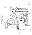
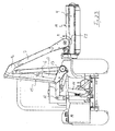
- the Mähund shown in Figure 1 and designated overall by 1 or Cutting device includes a self-propelled vehicle 2, which is not mandatory, a multi-part boom 3 and a Mowing head 4.
- the boom 3 is in the embodiment, three-membered formed and includes a first, short arm 5, one on it hinged middle arm 6 and a hinged outer Arm 7.
- Other constellations and configurations of the Jib 3 are possible.
- an outer arm 7 of Jib 3 pivotally connected to the mowing head 4.
- the Connection comprises a pivot axis 8, in the drawn Embodiment parallel to the direction of travel F of the vehicle. 2 runs.
- the vehicle 2 is designed as a narrow-track tractor to thus a flexible use also in narrow areas too enable. Even larger vehicles are possible.
- the unit of boom 3 and mowing head 4 is in the other than Mowing device 9 referred. As can be seen in Fig. 2, this is total of the vehicle 2 removable and to this in various positions coupled, for example, both at a rear as well as a front three-point hitch attachable. Also, the orientation can vary and thus the Working position of mowing head 4 changed from right to left become. As a counterweight for the mowing head 4, a tank 10, the Part of the mower 9 may be serve.
- the mowing head 4 with cutting and / or Impact may be provided and is interchangeable, so that also a pure hedge trimmer or the like can be mounted. Also, the mowing head can rotate several vertically or horizontally Cutting or impact rollers included. All these trainings are referred to here as mowing head 4. The following is for simplicity also the mowing and / or cutting device 1 referred to as mower 1.
- the first arm 5 is almost over one vertical hydraulic cylinder 11 about the joint 12th pivotable.
- the connecting joint arrangement 13 between the first and second arms 5, 6 is via a second To move hydraulic cylinder 14, the arm 6 is a parallel rod 15 assigned, these and the arm 6 from the Connecting joint assembly 13 to the hinge assembly 16, the the middle arm 6 and the parallel rod 15 with the outer Arm 7 connects, extend.
- a Joint parallelogram formed by a third Hydraulic cylinder 17 can be moved.
- the design of the Jib 3 is in terms of the number of its members and their Design variable.
- the mower head 4 is articulated on the outer arm 7 and around the Axis 8 rotatable.
- the linkage is so direct that a Pivot lever extending radially from the pivot axis 8 for Mowing head 4 would be dispensable. Rather extends from the upper edge region 18 of the horizontal position Mowing head 4 in the direction of travel a the pivot axis. 8 encompassing pipe section 19.
- the rotation plane 20 of the mowing head 4 is thus of the pivoting plane 21 of the outer arm 7 in Travel direction F spaced.
- the rotation plane 20 is in the embodiment in Direction of travel F before the movement plane 21 of the arm 7.
- a Collision between the parts mentioned is thus also in a Rotation of the mowing head 4 of 360 ° or more relative to the arm 7 excluded.
- the arm 7 comprises two superimposed drive members 22, 23, with respect to a Mirror plane 24 are symmetrical. In the mirror plane is also the pivot axis 8 for the movement of the mowing head 4 to the arm 7. Due to the mirror symmetry with respect to the plane 24 are both Swivel directions of the mowing head 4 equivalent and with the same Speed.
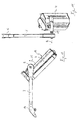
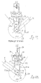
- FIG. 16 shows a vertical position of the mowing head 4 the in operation upper edge 18 facing outward, the Cutting and / or impact means therefore protected inside point.
- a transport position as in Figure 21 is shown. It is a very small width of Mowing device 9 is formed. Also about a narrow gauge tractor can therefore be formed in accordance with the invention, without the track of which would be surmounted laterally by the mowing device 9.
- the right-angled, inwardly pointing position of the mowing head 4 opposite the arm 7 can form an extreme position, from the from the cutting head 4 only in the direction of arrow 25 away can be pivoted. However, this is not mandatory. in the Embodiment is in the position of Figure 16, the upper Drive member 22 is almost fully extended.
- the drive members 22, 23 are here as a hydraulic cylinder formed, wherein the piston rods 22a, 23a with a pull rope 26 are connected.
- the traction cable 26 may in particular be a steel cable be. This rotates around a body of revolution 27, which the Swivel axle 8 firmly engages, with two full turns (see Fig. 20).
- For deflecting the pull cable 26 are additionally two Tensioning rollers 28, 29 are provided.
- About the pull cable 26 is therefore a Rotational movement of the mowing head 4 about the pivot axis 8 effected.
- a Pressed driver which in a complementary recess 27 a in a cable guide within the rotary body 27th positively engages.
- the transition from FIG. 16 to FIG. 17 also corresponds approximately the swiveling up of the mowing head during the transition from the Transport position according to Figure 21 in the horizontal position FIG. 23.
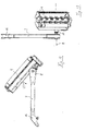
- the angle between mowing head 4 and arm 7 is 360 °, so they are parallel. Compared to the position of FIG 16 Thus, the mowing head 4 was pivoted by a total of 270 °. A upward or vertical position of the cutting head 4 to the outside pointing orientation of the cutting and / or impact means facilitates their maintenance and cleaning. The piston rod 22a is then almost completely retracted. Also an even bigger one Rotation angle depends on cylinder stroke and diameter of the Rotational body 27 possible, however, for most purposes not mandatory. Due to the rodless and the Preceding motion planes 20 and 21 is theoretical even a turn beyond the full circle possible.
- FIGS. 10, 12 and 14 likewise show an area of the Swinging up the mowing head 4 with respect to the outer arm 7 of the Jib 3 shown in Figure 14 with the parallel position of Mowing head 4 and arm 7 ends.
- the hydraulic elements used here for controlling the Cylinders 22, 23 are space-saving in the arm 7 of the boom. 3 arranged.
- FIG. 24 shows how a feed line B enters the Cylinder 22 is pressurized to thereby the Extend piston rod 22a and at the same time the piston rod 23a retract. This can be a force against the arrow 25 so that the cutting head 4 in the extreme shown in Figure 16 shifted position is shifted.
- FIG. 25 the conditions are exactly the opposite: it becomes the Supply line A in the piston 23 pressure medium.
- the Piston rod 23a extends; at the same time the piston rod 22a moves on, and pressure fluid flows via line B back into the tank. It is characterized by the pull cable 26 and the rotary body 27th thus applied a torque with respect to the axis 8, the one Pivoting of the mowing head 4 into the position according to FIG. 25, the figure 18 corresponds, causes.
- FIG. 27 shows a tensioning function for the traction cable 26:
- pressurizing the line B is at open check valve 31 and further open Safety valve 33 a uniform admission of both Piston of the cylinder 22, 23 made such that the Piston rods 22a, 23a are acted upon in the Einsinnsinn and thus evenly tighten the pull cable 26 without torque to exercise on the mowing head 4.
- This feature can be before everyone Operation of a Mähkopfverschwenkung be performed. In particular, she may be at the beginning of a work cycle if that Mower 1 is turned on, performed.
- the Bias of the cylinders 22, 23 is the body of revolution in each Angular position free of play with respect to the rotation about the axis 8.
- FIG Mowing head 4 pivoted from above onto an obstacle, open the Valves 31 and 34, so that here both piston crown sides connected to each other.
- All valves 30 to 35 can be in a unit in the arm. 7 be arranged in the vicinity of the cylinder 22, 23.
- the mowing device 9 thus as a compact and modular unit be formed.
Landscapes
- Life Sciences & Earth Sciences (AREA)
- Environmental Sciences (AREA)
- Harvester Elements (AREA)
Abstract
Description
- Fig. 1
- eine schematische Heckansicht eines erfindungsgemäßen Mäh- und/oder Schneidgeräts, das hier ein Fahrzeug umfaßt, an dessen Heck die Mähvorrichtung angeordnet ist, in einer nahe beim Fahrzeug liegenden horizontalen Arbeitsstellung des Mähkopfes,
- Fig. 2
- die Mähvorrichtung in Stellung nach Fig. 1 in vom Fahrzeug gelöster Abbildung,
- Fig. 3
- eine ähnliche Ansicht wie Fig. 1 mit einer ausgreifenden Schrägstellung des Mähkopfes an einer abwärts geneigten Böschung,
- Fig. 4
- die Mähvorrichtung in Stellung nach Fig. 3 in vom Fahrzeug gelöster Abbildung,
- Fig. 5
- eine schematische Heckansicht des Mäh- und/oder Schneidgeräts in einer vom Fahrzeug ausgreifenden und aufwärts verlagerten Horizontalstellung des Mähkopfes, etwa um eine Hecke oberseitig zu schneiden,
- Fig. 6
- eine ähnliche Ansicht wie Fig. 5 mit einem allerdings vertikal stehenden Mähkopf, etwa um ein Lichtprofil in Baumkronen oder Hecken zu schneiden,
- Fig. 7
- das Mäh- und/oder Schneidgerät in Stellung nach Fig. 6 in Ansicht von oben,
- Fig. 8
- das Mäh- und/oder Schneidgerät in Transportstellung mit nahe beim Fahrzeug vertikal stehendem Mähkopf in Ansicht von oben,
- Fig. 9
- die Mähvorrichtung in Stellung nach Fig. 8 in Abbildung ohne das Fahrzeug,
- Fig. 10
- den äußeren Auslegerarm mit daran angelenktem Mähkopf in einer schräg einwärts weisenden Stellung des Mähkopfes in Ansicht von hinten,
- Fig. 11
- den äußeren Auslegerarm mit daran angelenktem Mähkopf in Stellung nach Fig. 10 in Ansicht von oben,
- Fig. 12
- den äußeren Auslegerarm mit daran angelenktem Mähkopf in einer schräg auswärts und aufwärts weisenden Stellung des Mähkopfes in Ansicht von hinten,
- Fig. 13
- den äußeren Auslegerarm mit daran angelenktem Mähkopf in Stellung nach Fig. 12 in Ansicht von oben,
- Fig. 14
- den äußeren Auslegerarm mit daran angelenktem Mähkopf in einer horizontalen, die Schneidmittel aufwärts positionierenden Stellung des Mähkopfes in Ansicht von hinten,
- Fig. 15
- den äußeren Auslegerarm mit daran angelenktem Mähkopf in Stellung nach Fig. 14 in Ansicht von oben,
- Fig. 16
- eine schematische Ansicht der im äußeren Auslegerarm angeordneten Teile mit daran gehaltenem Mähkopf in Vertikalstellung des Mähkopfes,
- Fig. 17
- eine ähnliche Darstellung wie Fig. 16 in teilweise verschwenkter Stellung des Mähkopfes,
- Fig. 18
- eine ähnliche Darstellung wie Fig. 16 mit demgegenüber um weitere 270° verschwenkter Stellung des Mähkopfes,
- Fig. 19
- das Detail XIX in Fig. 18,
- Fig. 20
- das Detail nach Fig. 19 in Ansicht von oben,
- Fig. 21
- das Mäh- und/oder Schneidgerät in perspektivischer Ansicht von schräg hinten in Transportstellung des Mähkopfes,
- Fig. 22
- das Mäh- und/oder Schneidgerät in Ansicht von hinten während des Aufschwenkens des Auslegers bei vertikaler Halterung des Mähkopfes,
- Fig. 23
- das Mäh- und/oder Schneidgerät in Ansicht von hinten bei weiter fortschreitender Öffnung des Auslegers und Horizontalverschwenkung des Mähkopfes,
- Fig. 24
- eine schematische Ansicht der Hydraulik für die im Ausleger befindlichen Zylinder in weit eingeschwenkter Stellung des Mähkopfes,
- Fig. 25
- eine ähnliche Ansicht wie Fig. 24 mit gegenüber der dort gezeigten Stellung um 270° auswärts verschwenkter Stellung des Mähkopfes,
- Fig. 26
- eine ähnliche Ansicht wie Fig. 25 mit schwimmend gehaltenem Mähkopf,
- Fig. 27
- eine ähnliche Ansicht wie Fig. 26 mit einer Druckmittelbeaufschlagung beider Kolben zum Spannen des Zugseils,
- Fig. 28
- eine ähnliche Ansicht wie Fig. 27 mit aktiver Überlastsicherung zur Druckmittelabfuhr bei Verschwenken des Mähkopfes unter ein Hindernis,
- Fig. 29
- eine ähnliche Ansicht wie Fig. 28 mit einer in gegensinniger Richtung aktiven Überlastsicherung.
Claims (16)
- Mäh- und/oder Schneidgerät (1) mit einem sich von einem Fahrzeug (2) in Betriebsstellung auswärts erstreckenden, beweglichen Ausleger (3), an dem ein Mähkopf (4) schwenkbeweglich halterbar ist,
dadurch gekennzeichnet, daß die Schwenkhalterung des Mähkopfs (4) an dem Ausleger (3) gestängefrei ausgebildet ist. - Mäh- und/oder Schneidgerät nach Anspruch 1,
dadurch gekennzeichnet, daß der Mähkopf (4) ohne Ausbildung eines Schwenkhebels an dem Schwenkgelenk (8) gehalten ist. - Mäh- und/oder Schneidgerät (1) mit einem sich von einem Fahrzeug (2) in Betriebsstellung auswärts erstreckenden, beweglichen Ausleger (3), an dem ein Mähkopf (4) schwenkbeweglich halterbar ist, insbesondere nach einem der Ansprüche 1 oder 2,
dadurch gekennzeichnet, daß zumindest über einen Teilbereich des von dem Mähkopf (4) gegenüber einem äußeren Arm (7) des Auslegers (3) beschriebenen Kreisbogens zueinander gegensinnige Schwenkbewegungen des Mähkopfes (4) in mechanisch gleichwertiger Weise bewirkbar sind. - Mäh- und/oder Schneidgerät nach Anspruch 3,
dadurch gekennzeichnet, daß der dem Mähkopf zugewandte Arm (7) des Auslegers (3) um eine die Schwenkachse (8) des Mähkopfes (4) gegenüber dem Ausleger (3) umfassende Ebene (24) spiegelsymmetrisch ausgebildet ist. - Mäh- und/oder Schneidgerät nach einem der Ansprüche 1 bis 4,
dadurch gekennzeichnet, daß der Mähkopf (4) vor oder hinter der Erstreckungsebene (21) des Auslegers (3) liegt und um diesen schwenkbar ist. - Mäh- und/oder Schneidgerät nach Anspruch 5,
dadurch gekennzeichnet, daß der Mähkopf (4) in einer Transportstellung in einer im wesentlichen vertikalen Stellung halterbar ist. - Mäh- und/oder Schneidgerät nach einem der Ansprüche 5 oder 6,
dadurch gekennzeichnet, daß der Mähkopf (4) in einer im wesentlichen vertikalen Stellung mit nach außen gewandten Schneid- oder Schlagmitteln einer Wartung zugänglich ist. - Mäh- und/oder Schneidgerät nach einem der Ansprüche 1 bis 7,
dadurch gekennzeichnet, daß zur Bewirkung der Schwenkbewegung zwei gleichartige, im jeweiligen Schwenksinn eine Zugkraftbeaufschlagung bewirkende Antriebsorgane (22;23) vorgesehen sind. - Mäh- und/oder Schneidgerät nach einem der Ansprüche 1 bis 8,
dadurch gekennzeichnet, daß die Schwenkachse (8) für den Mähkopf (4) von einem mit diesem beweglichen Rotationskörper (27) umgeben ist. - Mäh- und/oder Schneidgerät nach Anspruch 9,
dadurch gekennzeichnet, daß der Rotationskörper (27) über seinen Umfang eine Lauffläche für ein Zugglied (26), insbesondere eine Kette oder ein Zugseil, umfaßt. - Mäh- und/oder Schneidgerät nach einem der Ansprüche 8 bis 10,
dadurch gekennzeichnet, daß im wesentlichen parallel zu dem dem Mähkopf (4) zugewandten Ende (7) des Auslegers (3) und parallel zueinander zwei Hydraulikzylinder (22;23) angeordnet sind, deren Kolbenstangen (22a;23a) jeweils mit einem flexiblen Zugglied (26) verbunden sind. - Mäh- und/oder Schneidgerät nach Anspruch 11,
dadurch gekennzeichnet, daß das Zugglied (26) als Drahtseil ausgebildet ist. - Mäh- und/oder Schneidgerät nach Anspruch 12,
dadurch gekennzeichnet, daß das Zugglied (26) den Rotationskörper (27) zumindest einmal vollständig umlaufend umgibt. - Mäh- und/oder Schneidgerät nach einem der Ansprüche 8 bis 13,
dadurch gekennzeichnet, daß für eine schwimmende Halterung des Mähkopfes (4) die beiden Antriebsorgane (22;23) miteinander kraftfrei verschaltbar sind. - Mäh- und/oder Schneidgerät nach einem der Ansprüche 1 bis 14,
dadurch gekennzeichnet, daß die Schwenkgeschwindigkeit des Mähkopfes (4) gegenüber dem äußeren Arm (7) des Auslegers (3) über den gesamten Schwenkwinkel konstant ist. - Mäh- und/oder Schneidgerät nach einem der Ansprüche 10 bis 15,
dadurch gekennzeichnet, daß das Zugseil durch Vorspannung der Zylinder (22;23) ständig gespannt und der Rotationskörper (27) somit spielfrei gehalten ist.
Applications Claiming Priority (2)
| Application Number | Priority Date | Filing Date | Title |
|---|---|---|---|
| DE10227261 | 2002-06-19 | ||
| DE10227261.1A DE10227261B4 (de) | 2002-06-19 | 2002-06-19 | Mäh- und/oder Schneidgerät |
Publications (2)
| Publication Number | Publication Date |
|---|---|
| EP1378157A1 true EP1378157A1 (de) | 2004-01-07 |
| EP1378157B1 EP1378157B1 (de) | 2009-08-12 |
Family
ID=29719226
Family Applications (1)
| Application Number | Title | Priority Date | Filing Date |
|---|---|---|---|
| EP03013936A Expired - Lifetime EP1378157B1 (de) | 2002-06-19 | 2003-06-20 | Mäh- und/oder Schneidgerät |
Country Status (4)
| Country | Link |
|---|---|
| EP (1) | EP1378157B1 (de) |
| AT (1) | ATE439032T1 (de) |
| DE (2) | DE10227261B4 (de) |
| DK (1) | DK1378157T3 (de) |
Cited By (6)
| Publication number | Priority date | Publication date | Assignee | Title |
|---|---|---|---|---|
| EP1759571A1 (de) * | 2005-04-22 | 2007-03-07 | Gerhard Dücker GmbH & Co. KG Landmaschinenfabrik | Mäh- und/oder Schneidgerät |
| FR2898242A1 (fr) * | 2006-03-07 | 2007-09-14 | Kuhn Audureau Sa Sa | Debroussailleuse munie d'un bras porte-outil avec un grand angle de rotation |
| NL2007296A (nl) * | 2010-08-25 | 2012-02-28 | Alois Pa Ttinger Maschinenfabrik Gmbh | Landbouwmachine. |
| EP2581687A1 (de) * | 2011-10-11 | 2013-04-17 | Robonaut GmbH | Vorrichtung und Fahrzeug zur Bearbeitung ebener Oberflächen |
| FR3033680A1 (fr) * | 2015-03-17 | 2016-09-23 | Rousseau | Faucheuse debroussailleuse avec au moins un bras articule et un outil de coupe relie a l'extremite libre du bras par un verin rotatif |
| GB2544462A (en) * | 2015-11-04 | 2017-05-24 | Kverneland Group Kerteminde As | Carrier arm assembly |
Families Citing this family (2)
| Publication number | Priority date | Publication date | Assignee | Title |
|---|---|---|---|---|
| DE102019133069B4 (de) * | 2019-12-04 | 2025-02-20 | MULAG FAHRZEUGWERK Heinz Wössner GmbH & Co. KG | Ausleger-Arbeitsgerät, selbstfahrende Arbeitsmaschine mit einem solchen Ausleger-Arbeitsgerät sowie ein Verfahren zum Detektieren der auf den Ausleger einwirkenden Belastungen |
| IT202100016472A1 (it) * | 2021-06-23 | 2022-12-23 | Gl 1 S R L | Braccio meccanico articolato |
Citations (6)
| Publication number | Priority date | Publication date | Assignee | Title |
|---|---|---|---|---|
| FR1422254A (fr) * | 1964-11-06 | 1965-12-24 | Perfectionnements aux broyeurs de végétaux à rotor | |
| US3949539A (en) * | 1971-12-22 | 1976-04-13 | Cartner Jack O | Hydraulic mower attachment |
| GB1467896A (en) | 1974-04-04 | 1977-03-23 | British Lely | Hedge cutting machines |
| GB2129265A (en) * | 1982-11-02 | 1984-05-16 | Turner Int | Mowers |
| GB2202122A (en) * | 1987-03-21 | 1988-09-21 | Mcconnel F W Ltd | Vegetation cutting apparatus |
| US6192665B1 (en) | 1999-03-19 | 2001-02-27 | Sylfor Inc. | Self-powered brush cutter |
Family Cites Families (1)
| Publication number | Priority date | Publication date | Assignee | Title |
|---|---|---|---|---|
| DD23873A (de) * |
-
2002
- 2002-06-19 DE DE10227261.1A patent/DE10227261B4/de not_active Expired - Lifetime
-
2003
- 2003-06-20 AT AT03013936T patent/ATE439032T1/de active
- 2003-06-20 DK DK03013936T patent/DK1378157T3/da active
- 2003-06-20 DE DE50311794T patent/DE50311794D1/de not_active Expired - Lifetime
- 2003-06-20 EP EP03013936A patent/EP1378157B1/de not_active Expired - Lifetime
Patent Citations (6)
| Publication number | Priority date | Publication date | Assignee | Title |
|---|---|---|---|---|
| FR1422254A (fr) * | 1964-11-06 | 1965-12-24 | Perfectionnements aux broyeurs de végétaux à rotor | |
| US3949539A (en) * | 1971-12-22 | 1976-04-13 | Cartner Jack O | Hydraulic mower attachment |
| GB1467896A (en) | 1974-04-04 | 1977-03-23 | British Lely | Hedge cutting machines |
| GB2129265A (en) * | 1982-11-02 | 1984-05-16 | Turner Int | Mowers |
| GB2202122A (en) * | 1987-03-21 | 1988-09-21 | Mcconnel F W Ltd | Vegetation cutting apparatus |
| US6192665B1 (en) | 1999-03-19 | 2001-02-27 | Sylfor Inc. | Self-powered brush cutter |
Cited By (8)
| Publication number | Priority date | Publication date | Assignee | Title |
|---|---|---|---|---|
| EP1759571A1 (de) * | 2005-04-22 | 2007-03-07 | Gerhard Dücker GmbH & Co. KG Landmaschinenfabrik | Mäh- und/oder Schneidgerät |
| FR2898242A1 (fr) * | 2006-03-07 | 2007-09-14 | Kuhn Audureau Sa Sa | Debroussailleuse munie d'un bras porte-outil avec un grand angle de rotation |
| NL2007296A (nl) * | 2010-08-25 | 2012-02-28 | Alois Pa Ttinger Maschinenfabrik Gmbh | Landbouwmachine. |
| FR2964007A1 (fr) * | 2010-08-25 | 2012-03-02 | Poettinger Alois Maschf | Machine agricole, en particulier dispositif de fauchage |
| EP2581687A1 (de) * | 2011-10-11 | 2013-04-17 | Robonaut GmbH | Vorrichtung und Fahrzeug zur Bearbeitung ebener Oberflächen |
| FR3033680A1 (fr) * | 2015-03-17 | 2016-09-23 | Rousseau | Faucheuse debroussailleuse avec au moins un bras articule et un outil de coupe relie a l'extremite libre du bras par un verin rotatif |
| GB2544462A (en) * | 2015-11-04 | 2017-05-24 | Kverneland Group Kerteminde As | Carrier arm assembly |
| AU2016349237B2 (en) * | 2015-11-04 | 2021-03-04 | Kverneland Group Kerteminde As | Carrier arm assembly |
Also Published As
| Publication number | Publication date |
|---|---|
| DE10227261A1 (de) | 2004-01-29 |
| DE10227261B4 (de) | 2016-02-18 |
| EP1378157B1 (de) | 2009-08-12 |
| DK1378157T3 (da) | 2009-11-16 |
| ATE439032T1 (de) | 2009-08-15 |
| DE50311794D1 (de) | 2009-09-24 |
Similar Documents
| Publication | Publication Date | Title |
|---|---|---|
| EP0569836A1 (de) | Fahrzeug mit mindestens einem schwenkbar angeschlossenen Arbeitswerkzeug | |
| EP0872170A2 (de) | Heuwerbungsmaschine | |
| EP0807377A2 (de) | Vorrichtung zum Anschliessen eines aus der Arbeitsstellung in eine Transportstellung höhenverstellbares Gerätes an ein Fahrzeug | |
| DE69300977T2 (de) | Heumaschine mit dynamischer Entlastungsvorrichtung | |
| WO2001054483A1 (de) | Rahmen eines landwirtschaftlichen arbeitsgeräts | |
| EP2532221A1 (de) | Mähdeck | |
| DE1938698A1 (de) | Aufhaengung fuer eine Maeheinheit in einer Landmaschine | |
| DE10321683B4 (de) | Pfosten-Freimäher und Verfahren zum Einsatz des Freimähers | |
| EP1095555B1 (de) | Heuwerbungsmaschine | |
| EP1378157B1 (de) | Mäh- und/oder Schneidgerät | |
| DE10128547B4 (de) | Arbeitsgerät zum Anbau an ein Fahrzeug | |
| EP0807376B1 (de) | Anfahrschutz für ein an ein Fahrzeug anschliessbares Mähwerk | |
| EP1847168A1 (de) | Mähgerät zum Freischneiden von Zaunpfählen | |
| DE10149364A1 (de) | Mähmaschine | |
| EP0914761A1 (de) | Aufhängung für beidseitig an einem Trägerfahrzeug angebrachte Arbeitsaggregate | |
| EP3804493B1 (de) | Mähwerk mit einer schutzvorrichtung und arbeitszug mit dem mähwerk | |
| DE4108449C2 (de) | ||
| DE2160773A1 (de) | Mähwerk | |
| EP1652419B1 (de) | Mähvorrichtung, und damit ausgestattetes Mähfahrzeug | |
| DE69315741T2 (de) | Landwirtschaftliche Maschine, insbesondere Mähmaschine, mit einer verbesserten Vorrichtung zur Übertragung des Antriebs | |
| DE69307613T2 (de) | Mit einem Schlepper zu verbindender Mäher mit einer verbesserten Abstellvorrichtung | |
| DE2151156A1 (de) | Maehmaschine mit stengelquetschvorrichtung | |
| DE102004025478B4 (de) | Landwirtschaftliche Maschine | |
| DE3031566A1 (de) | Pflegeeinrichtung fuer bankette, strassenraender, boeschungen, graeben etc. | |
| AT501972B1 (de) | Mähmaschine |
Legal Events
| Date | Code | Title | Description |
|---|---|---|---|
| PUAI | Public reference made under article 153(3) epc to a published international application that has entered the european phase |
Free format text: ORIGINAL CODE: 0009012 |
|
| AK | Designated contracting states |
Kind code of ref document: A1 Designated state(s): AT BE BG CH CY CZ DE DK EE ES FI FR GB GR HU IE IT LI LU MC NL PT RO SE SI SK TR |
|
| AX | Request for extension of the european patent |
Extension state: AL LT LV MK |
|
| 17P | Request for examination filed |
Effective date: 20040618 |
|
| AKX | Designation fees paid |
Designated state(s): AT CH DE DK FR LI NL |
|
| GRAP | Despatch of communication of intention to grant a patent |
Free format text: ORIGINAL CODE: EPIDOSNIGR1 |
|
| GRAS | Grant fee paid |
Free format text: ORIGINAL CODE: EPIDOSNIGR3 |
|
| GRAA | (expected) grant |
Free format text: ORIGINAL CODE: 0009210 |
|
| AK | Designated contracting states |
Kind code of ref document: B1 Designated state(s): AT CH DE DK FR LI NL |
|
| REG | Reference to a national code |
Ref country code: CH Ref legal event code: EP |
|
| REF | Corresponds to: |
Ref document number: 50311794 Country of ref document: DE Date of ref document: 20090924 Kind code of ref document: P |
|
| REG | Reference to a national code |
Ref country code: DK Ref legal event code: T3 |
|
| PLBE | No opposition filed within time limit |
Free format text: ORIGINAL CODE: 0009261 |
|
| STAA | Information on the status of an ep patent application or granted ep patent |
Free format text: STATUS: NO OPPOSITION FILED WITHIN TIME LIMIT |
|
| 26N | No opposition filed |
Effective date: 20100517 |
|
| REG | Reference to a national code |
Ref country code: CH Ref legal event code: PL |
|
| REG | Reference to a national code |
Ref country code: FR Ref legal event code: ST Effective date: 20110228 |
|
| PG25 | Lapsed in a contracting state [announced via postgrant information from national office to epo] |
Ref country code: CH Free format text: LAPSE BECAUSE OF NON-PAYMENT OF DUE FEES Effective date: 20100630 Ref country code: LI Free format text: LAPSE BECAUSE OF NON-PAYMENT OF DUE FEES Effective date: 20100630 |
|
| PG25 | Lapsed in a contracting state [announced via postgrant information from national office to epo] |
Ref country code: FR Free format text: LAPSE BECAUSE OF NON-PAYMENT OF DUE FEES Effective date: 20100630 |
|
| PGFP | Annual fee paid to national office [announced via postgrant information from national office to epo] |
Ref country code: NL Payment date: 20220630 Year of fee payment: 20 Ref country code: DK Payment date: 20220630 Year of fee payment: 20 Ref country code: DE Payment date: 20220630 Year of fee payment: 20 |
|
| PGFP | Annual fee paid to national office [announced via postgrant information from national office to epo] |
Ref country code: AT Payment date: 20220630 Year of fee payment: 20 |
|
| REG | Reference to a national code |
Ref country code: DE Ref legal event code: R071 Ref document number: 50311794 Country of ref document: DE |
|
| REG | Reference to a national code |
Ref country code: NL Ref legal event code: MK Effective date: 20230619 |
|
| REG | Reference to a national code |
Ref country code: DK Ref legal event code: EUP Expiry date: 20230620 |
|
| REG | Reference to a national code |
Ref country code: AT Ref legal event code: MK07 Ref document number: 439032 Country of ref document: AT Kind code of ref document: T Effective date: 20230620 |