EP1377465B1 - Pneumatic tire with reinforced bead part - Google Patents
Pneumatic tire with reinforced bead part Download PDFInfo
- Publication number
- EP1377465B1 EP1377465B1 EP01974905A EP01974905A EP1377465B1 EP 1377465 B1 EP1377465 B1 EP 1377465B1 EP 01974905 A EP01974905 A EP 01974905A EP 01974905 A EP01974905 A EP 01974905A EP 1377465 B1 EP1377465 B1 EP 1377465B1
- Authority
- EP
- European Patent Office
- Prior art keywords
- bead
- bead part
- tire
- pneumatic tire
- reinforced
- Prior art date
- Legal status (The legal status is an assumption and is not a legal conclusion. Google has not performed a legal analysis and makes no representation as to the accuracy of the status listed.)
- Expired - Lifetime
Links
- 239000011324 bead Substances 0.000 title claims description 61
- 238000000034 method Methods 0.000 description 2
- 229910000831 Steel Inorganic materials 0.000 description 1
- 238000010276 construction Methods 0.000 description 1
- 238000004519 manufacturing process Methods 0.000 description 1
- 238000000465 moulding Methods 0.000 description 1
- 239000010959 steel Substances 0.000 description 1
- 238000004804 winding Methods 0.000 description 1
Images

Classifications
-
- B—PERFORMING OPERATIONS; TRANSPORTING
- B60—VEHICLES IN GENERAL
- B60C—VEHICLE TYRES; TYRE INFLATION; TYRE CHANGING; CONNECTING VALVES TO INFLATABLE ELASTIC BODIES IN GENERAL; DEVICES OR ARRANGEMENTS RELATED TO TYRES
- B60C9/00—Reinforcements or ply arrangement of pneumatic tyres
- B60C9/02—Carcasses
-
- B—PERFORMING OPERATIONS; TRANSPORTING
- B60—VEHICLES IN GENERAL
- B60C—VEHICLE TYRES; TYRE INFLATION; TYRE CHANGING; CONNECTING VALVES TO INFLATABLE ELASTIC BODIES IN GENERAL; DEVICES OR ARRANGEMENTS RELATED TO TYRES
- B60C15/00—Tyre beads, e.g. ply turn-up or overlap
- B60C15/04—Bead cores
- B60C15/05—Bead cores multiple, i.e. with two or more cores in each bead
-
- B—PERFORMING OPERATIONS; TRANSPORTING
- B60—VEHICLES IN GENERAL
- B60C—VEHICLE TYRES; TYRE INFLATION; TYRE CHANGING; CONNECTING VALVES TO INFLATABLE ELASTIC BODIES IN GENERAL; DEVICES OR ARRANGEMENTS RELATED TO TYRES
- B60C15/00—Tyre beads, e.g. ply turn-up or overlap
- B60C15/0009—Tyre beads, e.g. ply turn-up or overlap features of the carcass terminal portion
- B60C15/0081—Tyre beads, e.g. ply turn-up or overlap features of the carcass terminal portion the carcass plies folded around or between more than one bead core
-
- B—PERFORMING OPERATIONS; TRANSPORTING
- B60—VEHICLES IN GENERAL
- B60C—VEHICLE TYRES; TYRE INFLATION; TYRE CHANGING; CONNECTING VALVES TO INFLATABLE ELASTIC BODIES IN GENERAL; DEVICES OR ARRANGEMENTS RELATED TO TYRES
- B60C15/00—Tyre beads, e.g. ply turn-up or overlap
- B60C15/02—Seating or securing beads on rims
- B60C15/024—Bead contour, e.g. lips, grooves, or ribs
- B60C15/0247—Bead contour, e.g. lips, grooves, or ribs with reverse bead seat inclination, i.e. the axially inner diameter of the bead seat is bigger than the axially outer diameter thereof
-
- Y—GENERAL TAGGING OF NEW TECHNOLOGICAL DEVELOPMENTS; GENERAL TAGGING OF CROSS-SECTIONAL TECHNOLOGIES SPANNING OVER SEVERAL SECTIONS OF THE IPC; TECHNICAL SUBJECTS COVERED BY FORMER USPC CROSS-REFERENCE ART COLLECTIONS [XRACs] AND DIGESTS
- Y10—TECHNICAL SUBJECTS COVERED BY FORMER USPC
- Y10T—TECHNICAL SUBJECTS COVERED BY FORMER US CLASSIFICATION
- Y10T152/00—Resilient tires and wheels
- Y10T152/10—Tires, resilient
- Y10T152/10495—Pneumatic tire or inner tube
- Y10T152/10819—Characterized by the structure of the bead portion of the tire
Definitions
- the present invention relates to a pneumatic tire with reinforced bead part installed on a rim without flange and, more particularly, to a pneumatic tire wherein bead part is reinforced by using a lump, which is not used in the prior art, placed between beads so that the bead part is not easily released from the rim of the tire while driving under low air pressure of tire.
- the conventional tire having reinforced bead part has the problem that the tire is easily released from the rim when tire is deflated while driving, when the tire is installed on a rim without flange.
- a tire corresponding to the preamble of claim 1 is known from US-A- 5 513 686.
- the object of the present invention is to solve the problem of bead part of the conventional pneumatic tire.
- a rubber lump is installed between beads to prevent the tire from releasing from the rim when the tire is deflated so that car accidents can be prevented.
- a rubber lump is installed between two beads which are arranged doubly, or two fold lumps are placed enclosing a single bead, the lump having the role that the bead part is not easily released from the bead seat of the rim when the tire is deflated.
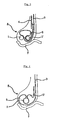
- Fig. 2 is a cross-sectional view of the bead portion of the tire according to the first embodiment of the present invention, wherein two beads 1, 1' are placed facing each other with predetermined interval in the bead part 8 which is arranged on a bead seat, a rubber lump 5 is installed on said two beads passing through the beads, and a carcass ply 3 winds around said rubber lump 5.
- a carcass ply 3 is installed winding on the molding drum and a rubber lump 5 winds at an arbitrary point between both ends and center portion of the carcass ply 3, and the carcass ply 3 is turned up.
- the first bead 1 is placed at the front of the rubber lump 5 and the second bead 1' is placed at the rear of the rubber lump 5.
- Fig. 3 is a cross-sectional view of the bead part of the tire according to the second embodiment of the present invention, wherein a steel insert 4 is inserted on the rubber lump 5 parallel to the carcass ply 3, so that the release of bead part from bead seat becomes more difficult.
- Fig. 4 is a cross-sectional view of the bead portion of the tire according to the third embodiment of the present invention, wherein two fold rubber lumps 5, 5' are installed enclosing the single bead 1.
- the basic principle is the same as that of the first embodiment, the two fold rubber lump 5, 5' preventing the movement of bead 1 when the tire is deflated.
- the bead part is not easily released from the rim when the tire is deflated or under-inflated while driving, and the function of the tire is not affected. Therefore, the car accidents caused by released bead part can be prevented.
Landscapes
- Engineering & Computer Science (AREA)
- Mechanical Engineering (AREA)
- Tires In General (AREA)
Description
- The present invention relates to a pneumatic tire with reinforced bead part installed on a rim without flange and, more particularly, to a pneumatic tire wherein bead part is reinforced by using a lump, which is not used in the prior art, placed between beads so that the bead part is not easily released from the rim of the tire while driving under low air pressure of tire.
- In conventional pneumatic tires, as shown in the Fig. 1,
strong apex 2 is inserted in abead part 8 where bead is placed, orinsert 4 is installed, or the position of the end ofcarcass ply 3 is changed to reinforce the bead part. By using this method, cornering performance and durability of bead part are enhanced but the comfort of driving a car is reduced. Thenumber 6 in Fig. 1 represents a flange. - In addition, the conventional tire having reinforced bead part has the problem that the tire is easily released from the rim when tire is deflated while driving, when the tire is installed on a rim without flange.
- A tire corresponding to the preamble of
claim 1 is known from US-A- 5 513 686. - The object of the present invention is to solve the problem of bead part of the conventional pneumatic tire. For this object, a rubber lump is installed between beads to prevent the tire from releasing from the rim when the tire is deflated so that car accidents can be prevented.
-
- Fig. 1 is a sectional view of the bead part of a conventional tire,
- Fig. 2 is a sectional view of the bead part of a tire according to first embodiment of the present invention,
- Fig. 3 is a sectional view of the bead part of a tire according to the second embodiment of the present invention, and
- Fig. 4 is a sectional view of the bead part of a tire according to the third embodiment of the present invention.
-
1, 1': bead, 2: apex 3: carcass ply 4: insert 5, 5': rubber lump 6: flange 7: bead seat 8: bead portion - To achieve the object as stated above, a rubber lump is installed between two beads which are arranged doubly, or two fold lumps are placed enclosing a single bead, the lump having the role that the bead part is not easily released from the bead seat of the rim when the tire is deflated.
- The construction of the pneumatic tire having reinforced bead part of the present invention will be described in detail with reference to the accompanying drawings.
- Fig. 2 is a cross-sectional view of the bead portion of the tire according to the first embodiment of the present invention, wherein two
beads 1, 1' are placed facing each other with predetermined interval in thebead part 8 which is arranged on a bead seat, arubber lump 5 is installed on said two beads passing through the beads, and acarcass ply 3 winds around saidrubber lump 5. - Now the process of manufacturing the bead part to which a
rubber lump 5 is applied will be described. - A
carcass ply 3 is installed winding on the molding drum and arubber lump 5 winds at an arbitrary point between both ends and center portion of thecarcass ply 3, and thecarcass ply 3 is turned up. Among two beads, thefirst bead 1 is placed at the front of therubber lump 5 and the second bead 1' is placed at the rear of therubber lump 5. - Accordingly, when the tire is deflated or under-inflated while driving, the
carcass ply 3 is pulled toward the side of the tire, and due to this force therubber lump 5 between twobeads 1, 1' can prevent thebead part 8 from releasing from thebead seat 7. In this way the problem of prior art tire that the bead part is easily released from the rim due to the movement of bead part from bead seat of the rim to wall area when the tire is deflated can be solved. - Fig. 3 is a cross-sectional view of the bead part of the tire according to the second embodiment of the present invention, wherein a
steel insert 4 is inserted on therubber lump 5 parallel to thecarcass ply 3, so that the release of bead part from bead seat becomes more difficult. - Fig. 4 is a cross-sectional view of the bead portion of the tire according to the third embodiment of the present invention, wherein two
fold rubber lumps 5, 5' are installed enclosing thesingle bead 1. The basic principle is the same as that of the first embodiment, the twofold rubber lump 5, 5' preventing the movement ofbead 1 when the tire is deflated. - By using the pneumatic tire with reinforced bead part of the present invention in a tire without flange, the bead part is not easily released from the rim when the tire is deflated or under-inflated while driving, and the function of the tire is not affected. Therefore, the car accidents caused by released bead part can be prevented.
Claims (3)
- A pneumatic tire with reinforced bead part (8), wherein two bead cores (1, 1') are placed facing each other with predetermined interval in the bead part (8) which is arranged on a bead seat, a rubber lump (5) is installed on said two beads passing through the bead cores, and a carcass ply (3) winds around said rubber lump (5).
- A pneumatic tire with reinforced bead part, wherein a bead core (1) is placed in the bead part (8) which is arranged on a bead seat, two fold rubber lumps (5, 5') are installed on both sides of said bead core, and a carcass ply (3) winds around said rubber lump (5, 5').
- The pneumatic tire with reinforced bead part of claim 1 or claim 2, wherein an insert (4) is inserted on the rubber lump (5) parallel to the carcass ply (3).
Applications Claiming Priority (3)
| Application Number | Priority Date | Filing Date | Title |
|---|---|---|---|
| KR10-2001-0014257A KR100392424B1 (en) | 2001-03-20 | 2001-03-20 | Pneumatic Tire with Reinforced Bead Part |
| KR2001014257 | 2001-03-20 | ||
| PCT/KR2001/001540 WO2002074559A1 (en) | 2001-03-20 | 2001-09-13 | Pneumatic tire with reinforced bead part |
Publications (3)
| Publication Number | Publication Date |
|---|---|
| EP1377465A1 EP1377465A1 (en) | 2004-01-07 |
| EP1377465A4 EP1377465A4 (en) | 2005-12-21 |
| EP1377465B1 true EP1377465B1 (en) | 2007-02-21 |
Family
ID=19707129
Family Applications (1)
| Application Number | Title | Priority Date | Filing Date |
|---|---|---|---|
| EP01974905A Expired - Lifetime EP1377465B1 (en) | 2001-03-20 | 2001-09-13 | Pneumatic tire with reinforced bead part |
Country Status (6)
| Country | Link |
|---|---|
| US (1) | US20040134584A1 (en) |
| EP (1) | EP1377465B1 (en) |
| JP (1) | JP2004522644A (en) |
| KR (1) | KR100392424B1 (en) |
| DE (1) | DE60126835T2 (en) |
| WO (1) | WO2002074559A1 (en) |
Family Cites Families (11)
| Publication number | Priority date | Publication date | Assignee | Title |
|---|---|---|---|---|
| EP0077161A3 (en) * | 1981-10-09 | 1984-03-21 | Dunlop Limited | A tyre |
| KR940003077Y1 (en) * | 1989-01-31 | 1994-05-12 | 주식회사 금성사 | Over voltage protective apparatus |
| KR960008031Y1 (en) * | 1992-07-22 | 1996-09-23 | 윤양중 | Improved bead structure for pneumatic radial tyre |
| JP2697547B2 (en) * | 1993-03-11 | 1998-01-14 | 日本電気株式会社 | Semiconductor integrated circuit device |
| FR2707561A1 (en) * | 1993-07-12 | 1995-01-20 | Michelin & Cie | Tire structure for heavy goods vehicles. |
| FR2716645B1 (en) * | 1994-02-28 | 1996-04-19 | Michelin & Cie | Tire with beads of improved structure and assembly of such a tire with a suitable rim. |
| JP2966756B2 (en) * | 1995-03-30 | 1999-10-25 | 住友ゴム工業株式会社 | Heavy duty tire for 15mm taper rim |
| JPH10338001A (en) * | 1997-06-09 | 1998-12-22 | Yokohama Rubber Co Ltd:The | Pneumatic tire |
| FR2773518A1 (en) * | 1998-01-12 | 1999-07-16 | Michelin & Cie | TIRE SADDLE WITH CIRCUMFERENTIAL REINFORCEMENT ELEMENTS |
| JP4244246B2 (en) * | 1998-10-15 | 2009-03-25 | 株式会社ブリヂストン | Pneumatic tire |
| JP2000301917A (en) * | 1999-04-19 | 2000-10-31 | Bridgestone Corp | Pneumatic radial tire for heavy load |
-
2001
- 2001-03-20 KR KR10-2001-0014257A patent/KR100392424B1/en not_active Expired - Fee Related
- 2001-09-13 EP EP01974905A patent/EP1377465B1/en not_active Expired - Lifetime
- 2001-09-13 WO PCT/KR2001/001540 patent/WO2002074559A1/en not_active Ceased
- 2001-09-13 US US10/472,604 patent/US20040134584A1/en not_active Abandoned
- 2001-09-13 DE DE60126835T patent/DE60126835T2/en not_active Expired - Lifetime
- 2001-09-13 JP JP2002573247A patent/JP2004522644A/en not_active Ceased
Also Published As
| Publication number | Publication date |
|---|---|
| DE60126835T2 (en) | 2007-12-06 |
| US20040134584A1 (en) | 2004-07-15 |
| EP1377465A1 (en) | 2004-01-07 |
| EP1377465A4 (en) | 2005-12-21 |
| WO2002074559A1 (en) | 2002-09-26 |
| KR100392424B1 (en) | 2003-07-23 |
| KR20020074316A (en) | 2002-09-30 |
| JP2004522644A (en) | 2004-07-29 |
| DE60126835D1 (en) | 2007-04-05 |
Similar Documents
| Publication | Publication Date | Title |
|---|---|---|
| JP2606146Y2 (en) | Pneumatic tire | |
| EP1011993A1 (en) | Run-flat tire with an improved bead to rim interface | |
| WO2009051260A1 (en) | Pneumatic tire | |
| JPH1024714A5 (en) | ||
| US20020153080A1 (en) | Pneumatic radial tires | |
| DE60124654D1 (en) | Triangular bead core construction for run-flat tires | |
| JP2005132361A (en) | Self supporting pneumatic tire | |
| AU2001285778A1 (en) | Aircraft tyre with improved tyre bead | |
| JPH08337104A (en) | Pneumatic tire | |
| EP1174287A3 (en) | Pneumatic radial tires | |
| US6516845B2 (en) | Support device within a tire cavity to provide runflat capability | |
| DE60029922D1 (en) | VEHICLE TIRES | |
| GB1577380A (en) | Wheel with tyre bead retainer | |
| JP3910679B2 (en) | Low pressure all-terrain vehicle pneumatic tire and rim assembly | |
| US20040134584A1 (en) | Pneumatic tire with reinforced bead part | |
| EP1377464B1 (en) | Pneumatic tire with reinforced bead part | |
| ATE318206T1 (en) | TIRE WITH SIDEWALL REINFORCEMENT LAYERS FOR TWO-WHEEL VEHICLES. | |
| AU2007203377B2 (en) | Pneumatic tire with reinforced bead part | |
| EP1108567A1 (en) | Pneumatic tire | |
| KR200245689Y1 (en) | Aircraft tires with reinforced side parts | |
| KR100405124B1 (en) | Pneumatic Tire with Reinforced Bead Part | |
| AU2001284533A1 (en) | Pneumatic tire with reinforced bead part | |
| KR100315651B1 (en) | Run-flat tire | |
| JP2001277823A (en) | Pneumatic tire with tube | |
| EP1013477A3 (en) | Pneumatic tyre |
Legal Events
| Date | Code | Title | Description |
|---|---|---|---|
| PUAI | Public reference made under article 153(3) epc to a published international application that has entered the european phase |
Free format text: ORIGINAL CODE: 0009012 |
|
| 17P | Request for examination filed |
Effective date: 20031007 |
|
| AK | Designated contracting states |
Kind code of ref document: A1 Designated state(s): AT BE CH CY DE DK ES FI FR GB GR IE IT LI LU MC NL PT SE TR |
|
| AX | Request for extension of the european patent |
Extension state: AL LT LV MK RO SI |
|
| RAP1 | Party data changed (applicant data changed or rights of an application transferred) |
Owner name: KUMHO TIRE CO., INC. |
|
| RIN1 | Information on inventor provided before grant (corrected) |
Inventor name: LEE, MYUNG-JIN Inventor name: PARK, BOK-SOO Inventor name: CHUNG, DOH-ZONG |
|
| A4 | Supplementary search report drawn up and despatched |
Effective date: 20051108 |
|
| RIC1 | Information provided on ipc code assigned before grant |
Ipc: 7B 60C 15/05 B Ipc: 7B 60C 9/02 A Ipc: 7B 60C 15/00 B |
|
| GRAP | Despatch of communication of intention to grant a patent |
Free format text: ORIGINAL CODE: EPIDOSNIGR1 |
|
| RBV | Designated contracting states (corrected) |
Designated state(s): DE FR GB IT |
|
| GRAS | Grant fee paid |
Free format text: ORIGINAL CODE: EPIDOSNIGR3 |
|
| GRAA | (expected) grant |
Free format text: ORIGINAL CODE: 0009210 |
|
| AK | Designated contracting states |
Kind code of ref document: B1 Designated state(s): DE FR GB IT |
|
| REG | Reference to a national code |
Ref country code: GB Ref legal event code: FG4D |
|
| REF | Corresponds to: |
Ref document number: 60126835 Country of ref document: DE Date of ref document: 20070405 Kind code of ref document: P |
|
| ET | Fr: translation filed | ||
| PLBE | No opposition filed within time limit |
Free format text: ORIGINAL CODE: 0009261 |
|
| STAA | Information on the status of an ep patent application or granted ep patent |
Free format text: STATUS: NO OPPOSITION FILED WITHIN TIME LIMIT |
|
| 26N | No opposition filed |
Effective date: 20071122 |
|
| PGFP | Annual fee paid to national office [announced via postgrant information from national office to epo] |
Ref country code: DE Payment date: 20091016 Year of fee payment: 9 |
|
| PGFP | Annual fee paid to national office [announced via postgrant information from national office to epo] |
Ref country code: FR Payment date: 20091016 Year of fee payment: 9 Ref country code: GB Payment date: 20091022 Year of fee payment: 9 Ref country code: IT Payment date: 20090929 Year of fee payment: 9 |
|
| GBPC | Gb: european patent ceased through non-payment of renewal fee |
Effective date: 20100913 |
|
| PG25 | Lapsed in a contracting state [announced via postgrant information from national office to epo] |
Ref country code: IT Free format text: LAPSE BECAUSE OF NON-PAYMENT OF DUE FEES Effective date: 20100913 |
|
| REG | Reference to a national code |
Ref country code: FR Ref legal event code: ST Effective date: 20110531 |
|
| REG | Reference to a national code |
Ref country code: DE Ref legal event code: R119 Ref document number: 60126835 Country of ref document: DE Effective date: 20110401 |
|
| PG25 | Lapsed in a contracting state [announced via postgrant information from national office to epo] |
Ref country code: DE Free format text: LAPSE BECAUSE OF NON-PAYMENT OF DUE FEES Effective date: 20110401 Ref country code: FR Free format text: LAPSE BECAUSE OF NON-PAYMENT OF DUE FEES Effective date: 20100930 |
|
| PG25 | Lapsed in a contracting state [announced via postgrant information from national office to epo] |
Ref country code: GB Free format text: LAPSE BECAUSE OF NON-PAYMENT OF DUE FEES Effective date: 20100913 |