EP1376826A2 - Motor rotor and manufacturing method thereof - Google Patents
Motor rotor and manufacturing method thereof Download PDFInfo
- Publication number
- EP1376826A2 EP1376826A2 EP03253646A EP03253646A EP1376826A2 EP 1376826 A2 EP1376826 A2 EP 1376826A2 EP 03253646 A EP03253646 A EP 03253646A EP 03253646 A EP03253646 A EP 03253646A EP 1376826 A2 EP1376826 A2 EP 1376826A2
- Authority
- EP
- European Patent Office
- Prior art keywords
- permanent magnet
- synthetic resin
- resin tube
- contraction
- percentage
- Prior art date
- Legal status (The legal status is an assumption and is not a legal conclusion. Google has not performed a legal analysis and makes no representation as to the accuracy of the status listed.)
- Withdrawn
Links
- 238000004519 manufacturing process Methods 0.000 title claims description 16
- 229920003002 synthetic resin Polymers 0.000 claims abstract description 45
- 239000000057 synthetic resin Substances 0.000 claims abstract description 45
- 238000010438 heat treatment Methods 0.000 claims abstract description 13
- 230000008602 contraction Effects 0.000 claims description 19
- 238000000034 method Methods 0.000 claims description 5
- 239000011248 coating agent Substances 0.000 claims description 4
- 238000000576 coating method Methods 0.000 claims description 4
- 239000012634 fragment Substances 0.000 description 4
- 239000000853 adhesive Substances 0.000 description 3
- 230000001070 adhesive effect Effects 0.000 description 3
- 238000005336 cracking Methods 0.000 description 3
- 230000006866 deterioration Effects 0.000 description 3
- 238000001746 injection moulding Methods 0.000 description 3
- 238000012986 modification Methods 0.000 description 3
- 230000004048 modification Effects 0.000 description 3
- 230000003247 decreasing effect Effects 0.000 description 2
- 239000000463 material Substances 0.000 description 2
- 229910000859 α-Fe Inorganic materials 0.000 description 2
- 229910000828 alnico Inorganic materials 0.000 description 1
- 238000004132 cross linking Methods 0.000 description 1
- 230000007547 defect Effects 0.000 description 1
- 230000003292 diminished effect Effects 0.000 description 1
- 238000010894 electron beam technology Methods 0.000 description 1
- 230000006698 induction Effects 0.000 description 1
- 238000009434 installation Methods 0.000 description 1
- 229920000098 polyolefin Polymers 0.000 description 1
- 229920005989 resin Polymers 0.000 description 1
- 239000011347 resin Substances 0.000 description 1
Images

Classifications
-
- H—ELECTRICITY
- H02—GENERATION; CONVERSION OR DISTRIBUTION OF ELECTRIC POWER
- H02K—DYNAMO-ELECTRIC MACHINES
- H02K1/00—Details of the magnetic circuit
- H02K1/06—Details of the magnetic circuit characterised by the shape, form or construction
- H02K1/22—Rotating parts of the magnetic circuit
- H02K1/27—Rotor cores with permanent magnets
-
- H—ELECTRICITY
- H02—GENERATION; CONVERSION OR DISTRIBUTION OF ELECTRIC POWER
- H02K—DYNAMO-ELECTRIC MACHINES
- H02K1/00—Details of the magnetic circuit
- H02K1/06—Details of the magnetic circuit characterised by the shape, form or construction
- H02K1/22—Rotating parts of the magnetic circuit
- H02K1/27—Rotor cores with permanent magnets
- H02K1/2706—Inner rotors
- H02K1/272—Inner rotors the magnetisation axis of the magnets being perpendicular to the rotor axis
- H02K1/274—Inner rotors the magnetisation axis of the magnets being perpendicular to the rotor axis the rotor consisting of two or more circumferentially positioned magnets
- H02K1/2753—Inner rotors the magnetisation axis of the magnets being perpendicular to the rotor axis the rotor consisting of two or more circumferentially positioned magnets the rotor consisting of magnets or groups of magnets arranged with alternating polarity
- H02K1/278—Surface mounted magnets; Inset magnets
-
- H—ELECTRICITY
- H02—GENERATION; CONVERSION OR DISTRIBUTION OF ELECTRIC POWER
- H02K—DYNAMO-ELECTRIC MACHINES
- H02K1/00—Details of the magnetic circuit
- H02K1/06—Details of the magnetic circuit characterised by the shape, form or construction
- H02K1/22—Rotating parts of the magnetic circuit
- H02K1/28—Means for mounting or fastening rotating magnetic parts on to, or to, the rotor structures
-
- H—ELECTRICITY
- H02—GENERATION; CONVERSION OR DISTRIBUTION OF ELECTRIC POWER
- H02K—DYNAMO-ELECTRIC MACHINES
- H02K15/00—Processes or apparatus specially adapted for manufacturing, assembling, maintaining or repairing of dynamo-electric machines
- H02K15/02—Processes or apparatus specially adapted for manufacturing, assembling, maintaining or repairing of dynamo-electric machines of stator or rotor bodies
- H02K15/03—Processes or apparatus specially adapted for manufacturing, assembling, maintaining or repairing of dynamo-electric machines of stator or rotor bodies having permanent magnets
Definitions
- the present invention relates to a motor rotor having permanent magnet mounted thereon and a method for manufacturing the same.
- Permanent magnets such as sintered ferrite magnets, ferrite bonded magnets, sintered Sm-Co magnets, Sm-Co bonded magnets, sintered Nd-Fe magnets, Nd-Fe bonded magnets and alnico magnets are used as permanent magnets for motors.
- permanent magnets such as sintered ferrite magnets, ferrite bonded magnets, sintered Sm-Co magnets, Sm-Co bonded magnets, sintered Nd-Fe magnets, Nd-Fe bonded magnets and alnico magnets are used as permanent magnets for motors.
- cracking, breaking or chipping can occur more easily. If a crack, break or chip occurs in the permanent magnet, a fragment falls into the motor, there potentially is a problem such as the fragment becoming stuck between the stator and the rotor causing locking of the shaft.
- a high reliability and resistance to cracking are required. Therefore, such damages to permanent magnets become problematic.
- motors used in vehicles contained a rotor such as the one shown in Figures 4 and 5.
- a permanent magnet 3 is fixed on shaft 1 via a bush 2.
- a synthetic resin layer 4 is formed in one piece at the periphery of permanent magnet 3.
- some motors contain a rotor in which the periphery of the permanent magnet is protected by covering it with a thin-walled metallic cover.
- An object of the present is to provide a motor rotor and a manufacturing method for protecting the permanent magnet.
- Another object is to prevent the deterioration of the permanent magnet resulting from the temperature during manufacturing.
- a further object is to lower the manufacturing costs.
- the synthetic resin tube shrinks to coat and protect the permanent magnet.
- the synthetic resin tube contracts from being heated.
- the percentage of contraction in the lateral direction is greater than the percentage of contraction in the axial direction.
- Placement of the synthetic resin tube around the permanent magnet can be performed easily.
- the method for manufacturing the motor rotor comprises covering the motor rotor with permanent magnet mounted with a heat-shrinkable synthetic resin tube.
- the synthetic resin tube is heat shrunk to coat the periphery of the permanent magnet.
- the permanent magnet can be coated easily with a synthetic resin by simply covering the permanent magnet with a synthetic resin and heating.
- the motor rotor further includes the synthetic resin tube having a percentage of contraction in the lateral direction greater than the percentage of contraction in the axial direction.
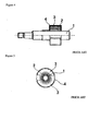
- Figure 1 shows a side view of a motor rotor according to the present invention
- Figure 2 shows a front view of the motor rotor of Figure 1;
- Figure 3 shows the synthetic resin tube before shrinkage
- Figure 4 shows the prior art motor rotor
- Figure 5 shows a front view of the prior art shown in Figure 4.
- the motor rotor of the present embodiment comprises a cylindrical bush 2 adhered to shaft 1.
- a pair of permanent magnets 3 having a cylindrical shape and the same curvature as the periphery of bush 2 are adhered and fixed.
- a bush 5 having an outer diameter that is narrower than bush 2 is fitted adjacent to bush 2.
- Shaft 1 comprises a chamfered portion 6 having an overall D-shaped cross-section at one end, at the extremity of which a screw portion 7 is formed.
- Permanent magnet 3 is a sintered Sm-Co magnet with its, size in the axial direction, being the same as that of bush 2. An appropriate adhesive is used to adhere permanent magnet 3 firmly to bush 2.
- Synthetic resin tube 8 stretches in the axial and lateral directions, from the center of bush 5 spanning permanent magnets 3 and bush 2, and covers them.
- Synthetic resin tube 8 is made of a thin-walled synthetic resin having thermal contraction properties and shrinks by heating.
- it can be manufactured by sending an electron beam to a synthetic resin of polyolefin to facilitate cross-linking giving it a shape memory property.
- the synthetic resin tube 8 has a short shrinkage time, and a small percentage of contraction in the axial direction (about 15%) with respect to the percentage of contraction in the lateral direction (about 50%).
- the synthetic resin used is incombustible, thin-walled, and has an appropriate flexibility.
- the materials use conditions and standards that can be selected accordingly.
- the assembly comprising bushes 2 and 5 as well as permanent magnet 3 is covered with a synthetic resin tube 8 (with a diameter before shrinkage larger than the permanent magnet).
- Resin tube 8 is cut to a specific length, and all components are positioned and aligned using an appropriate jig or the like.
- the assembly is heated to a given shrinking temperature in a high temperature atmosphere using a high temperature bath, a heating furnace, an oven, etc., to shrink synthetic resin tube 8 into close contact to cover the permanent magnet 3 and bushes 2 and 5.
- the heating conditions such as the heating temperature and time can be selected according to the type of synthetic resin tube 8, the size of the rotor, the materials, etc. Thus, the motor rotor can be manufactured easily.
- the synthetic resin tube 8 forms a thin-walled layer when it thermally contracts, the influence on the gap between the motor rotor and stator is small.
- the dimensional accuracy of the other parts (such as bush 2, permanent magnet 3 and stator) need not be considered.
- the present invention can be applied to all types of motors that contain permanent magnets, regardless of the type of motor such as direct current motors, alternate current motors, induction motors, etc. Furthermore, although it is particularly suited for those using cast magnets and sintered magnets, it can be applied equally to those with bonded magnets, plastic formed magnets and other types of permanent magnets.
- the permanent magnet is coated with a heat-shrinkable synthetic resin tube, the permanent magnet is protected. Also, manufacturing is easy and the manufacturing costs are decreased. In addition, the deterioration of the permanent magnet resulting from the manufacturing temperature is prevented.
- Positioning of the synthetic resin tube with respect to the permanent magnet can be performed easily.
- the permanent magnet mounted on the rotor By covering the permanent magnet mounted on the rotor with a synthetic resin tube and heating, the permanent magnet can be coated with a synthetic resin tube easily. Therefore, the rotor can be manufactured easily and the manufacturing cost can be decreased.
Landscapes
- Engineering & Computer Science (AREA)
- Power Engineering (AREA)
- Manufacturing & Machinery (AREA)
- Permanent Field Magnets Of Synchronous Machinery (AREA)
- Manufacture Of Motors, Generators (AREA)
Abstract
Description
- The present invention relates to a motor rotor having permanent magnet mounted thereon and a method for manufacturing the same.
- Among direct current motors and alternate current motors, there are motors with permanent magnets mounted on the rotor. Permanent magnets such as sintered ferrite magnets, ferrite bonded magnets, sintered Sm-Co magnets, Sm-Co bonded magnets, sintered Nd-Fe magnets, Nd-Fe bonded magnets and alnico magnets are used as permanent magnets for motors. However, depending on their nature, cracking, breaking or chipping can occur more easily. If a crack, break or chip occurs in the permanent magnet, a fragment falls into the motor, there potentially is a problem such as the fragment becoming stuck between the stator and the rotor causing locking of the shaft. In particular, for motors in vehicles, in an environment of high vibration, high temperatures, etc., a high reliability and resistance to cracking are required. Therefore, such damages to permanent magnets become problematic.
- In the past, motors used in vehicles contained a rotor such as the one shown in Figures 4 and 5. In the rotor shown in Figures 4 and 5, a permanent magnet 3 is fixed on shaft 1 via a
bush 2. Further, a synthetic resin layer 4 is formed in one piece at the periphery of permanent magnet 3. Thus, by coating the periphery of the permanent magnet 3 with a synthetic resin layer 4, permanent magnet 3 can be protected Therefore, even if a crack occurred, the fragment does not fall into the motor. This ensures that defects such as jamming of shaft 1 due to damage of permanent magnet 3 is prevented. - In addition, some motors contain a rotor in which the periphery of the permanent magnet is protected by covering it with a thin-walled metallic cover.
- However, the following problems exist with the above-mentioned rotors. To mold the synthetic resin layer 4, production facilities such as molds and injection molding machines are required, which increase costs. In addition, it is difficult to guarantee the necessary dimensional precision relative to the gap with the motor stator. When injection molding the synthetic resin layer, the rotor reaches a high temperature, and it is necessary to consider the deterioration of the magnetic characteristics of the permanent magnet and of the adhesive. When the permanent magnet is covered with a metallic cover, it is difficult to maintain the dimensional precision, and high manufacturing costs are incurred.
- An object of the present is to provide a motor rotor and a manufacturing method for protecting the permanent magnet.
- Another object is to prevent the deterioration of the permanent magnet resulting from the temperature during manufacturing.
- A further object is to lower the manufacturing costs.
- These and other objects and advantages are achieved by the present invention by coating the periphery of the permanent magnet with a heat-shrinkable synthetic resin tube.
- When the permanent is covered with a synthetic resin tube before shrinking and heating, the synthetic resin tube shrinks to coat and protect the permanent magnet.
- The synthetic resin tube contracts from being heated. The percentage of contraction in the lateral direction is greater than the percentage of contraction in the axial direction.
- Placement of the synthetic resin tube around the permanent magnet can be performed easily.
- The method for manufacturing the motor rotor comprises covering the motor rotor with permanent magnet mounted with a heat-shrinkable synthetic resin tube. The synthetic resin tube is heat shrunk to coat the periphery of the permanent magnet.
- The permanent magnet can be coated easily with a synthetic resin by simply covering the permanent magnet with a synthetic resin and heating.
- In addition, the motor rotor further includes the synthetic resin tube having a percentage of contraction in the lateral direction greater than the percentage of contraction in the axial direction.
- Therefore, placement of the synthetic resin tube relative to the permanent magnet can be performed easily.
- The above advantages and features are of representative embodiments only. It should be understood that they are not to be considered limitations on the invention as defined by the claims. Additional features and advantages of the invention will become apparent in the following description, from the drawings, and from the claims.
- The invention is illustrated by way of example and not limitation and the figures of the accompanying drawings in which like references denote like or corresponding parts, and in which:
- Figure 1 shows a side view of a motor rotor according to the present invention;
- Figure 2 shows a front view of the motor rotor of Figure 1;
- Figure 3 shows the synthetic resin tube before shrinkage;
- Figure 4 shows the prior art motor rotor; and
- Figure 5 shows a front view of the prior art shown in Figure 4.
- As shown in Figures 1 and 2, the motor rotor of the present embodiment comprises a
cylindrical bush 2 adhered to shaft 1. At the periphery ofbush 2, a pair of permanent magnets 3 having a cylindrical shape and the same curvature as the periphery ofbush 2 are adhered and fixed. In addition, abush 5 having an outer diameter that is narrower thanbush 2 is fitted adjacent tobush 2. - Shaft 1 comprises a chamfered portion 6 having an overall D-shaped cross-section at one end, at the extremity of which a
screw portion 7 is formed. Permanent magnet 3 is a sintered Sm-Co magnet with its, size in the axial direction, being the same as that ofbush 2. An appropriate adhesive is used to adhere permanent magnet 3 firmly to bush 2. - The periphery of the pair of permanent magnets is coated with a heat-shrinkable
synthetic resin tube 8.Synthetic resin tube 8 stretches in the axial and lateral directions, from the center ofbush 5 spanning permanent magnets 3 andbush 2, and covers them. -
Synthetic resin tube 8 is made of a thin-walled synthetic resin having thermal contraction properties and shrinks by heating. For example, it can be manufactured by sending an electron beam to a synthetic resin of polyolefin to facilitate cross-linking giving it a shape memory property. - In the present embodiment, the
synthetic resin tube 8 has a short shrinkage time, and a small percentage of contraction in the axial direction (about 15%) with respect to the percentage of contraction in the lateral direction (about 50%). The synthetic resin used is incombustible, thin-walled, and has an appropriate flexibility. In addition, the materials use conditions and standards that can be selected accordingly. - The method for manufacturing a motor rotor according to the present embodiment is shown in Figure 3.
- The
assembly comprising bushes Resin tube 8 is cut to a specific length, and all components are positioned and aligned using an appropriate jig or the like. The assembly is heated to a given shrinking temperature in a high temperature atmosphere using a high temperature bath, a heating furnace, an oven, etc., to shrinksynthetic resin tube 8 into close contact to cover the permanent magnet 3 andbushes synthetic resin tube 8, the size of the rotor, the materials, etc. Thus, the motor rotor can be manufactured easily. - In addition, if there is a protrusion, an edge, or the like on the permanent magnet which contacts the
synthetic resin tube 8, cracking may occur in thesynthetic resin tube 8. Therefore, if needed, a chamfer or a fillet may be created. - Since permanent magnet 3 is protected by
synthetic resin tube 8, even if a crack, break or chip occurs to permanent magnet 3, the fragment does not fall into the motor. Therefore, the reliability and durability of the motor is increased. Sincesynthetic resin tube 8 contracts in the lateral direction more than it contracts in the axial direction due to heating, the positioning of the synthetic resin tube relative to the permanent magnet can be performed easily. - Since the
synthetic resin tube 8 forms a thin-walled layer when it thermally contracts, the influence on the gap between the motor rotor and stator is small. The dimensional accuracy of the other parts (such asbush 2, permanent magnet 3 and stator) need not be considered. - Since there is no influence on the magnetic properties of permanent magnet 3 and the adhesive between permanent magnet 3 and
bush 2 from the heating process, there is no need to consider those in particular. In addition, the manufacturing process employs a simple heating device so that installations of molds and injection molding machines of the past are unnecessary. Therefore, the cost can be considerably diminished. - In addition, the present invention can be applied to all types of motors that contain permanent magnets, regardless of the type of motor such as direct current motors, alternate current motors, induction motors, etc. Furthermore, although it is particularly suited for those using cast magnets and sintered magnets, it can be applied equally to those with bonded magnets, plastic formed magnets and other types of permanent magnets.
- As described above, since the permanent magnet is coated with a heat-shrinkable synthetic resin tube, the permanent magnet is protected. Also, manufacturing is easy and the manufacturing costs are decreased. In addition, the deterioration of the permanent magnet resulting from the manufacturing temperature is prevented.
- Positioning of the synthetic resin tube with respect to the permanent magnet can be performed easily.
- By covering the permanent magnet mounted on the rotor with a synthetic resin tube and heating, the permanent magnet can be coated with a synthetic resin tube easily. Therefore, the rotor can be manufactured easily and the manufacturing cost can be decreased.
- For the convenience of the reader, the above description has focused on a representative sample of all possible embodiments, a sample that teaches the principles of the invention and conveys the best mode contemplated for carrying it out. The description has not attempted to exhaustively enumerate all possible variations. Other undescribed variations or modifications may be possible. For example, where multiple alternative embodiments are described, in many cases it will be possible to combine elements of different embodiments, or to combine elements of the embodiments described here with other modifications or variations that are not expressly described. Many of those undescribed variations, modifications and variations are within the literal scope of the following claims, and others are equivalent.
Claims (6)
- A motor rotor comprising:a permanent magnet secured to said motor rotor; anda heat-shrinkable synthetic resin tube coating applied to said permanent magnet.
- The motor rotor according to claim 1, wherein said synthetic resin tube has a percentage of contraction in a lateral direction and a percentage of contraction in an axial direction, said percentage of contraction in the lateral direction being greater than said percentage of contraction in the axial direction.
- A method for manufacturing a motor rotor having a permanent magnet mounted thereon, comprising the steps of:covering the permanent magnet with a heat-shrinkable synthetic resin tube; andheating said synthetic resin tube to coat a periphery of the permanent magnet.
- The method for manufacturing a motor rotor according to Claim 3, wherein said synthetic resin tube has a percentage of contraction in a lateral direction and a percentage of contraction in the axial direction from heating, said percentage of contraction in the lateral direction being greater than said percentage of contraction in the axial direction.
- A motor comprising:A motor rotor, said motor rotor having a permanent magnet mounted thereon and a heat-shrinkable synthetic resin tube coating applied to said permanent magnet.
- The motor according to Claim 5, wherein said synthetic resin tube has a percentage of contraction in a lateral direction and a percentage of contraction in an axial direction, said percentage of contraction in the lateral direction being greater than said percentage of contraction in the axial direction.
Applications Claiming Priority (2)
| Application Number | Priority Date | Filing Date | Title |
|---|---|---|---|
| JP2002175781A JP2004023901A (en) | 2002-06-17 | 2002-06-17 | Motor rotor and method of manufacturing the same |
| JP2002175781 | 2002-06-17 |
Publications (2)
| Publication Number | Publication Date |
|---|---|
| EP1376826A2 true EP1376826A2 (en) | 2004-01-02 |
| EP1376826A3 EP1376826A3 (en) | 2005-01-19 |
Family
ID=29717446
Family Applications (1)
| Application Number | Title | Priority Date | Filing Date |
|---|---|---|---|
| EP03253646A Withdrawn EP1376826A3 (en) | 2002-06-17 | 2003-06-10 | Motor rotor and manufacturing method thereof |
Country Status (5)
| Country | Link |
|---|---|
| US (1) | US20040051415A1 (en) |
| EP (1) | EP1376826A3 (en) |
| JP (1) | JP2004023901A (en) |
| KR (1) | KR20040002581A (en) |
| CN (1) | CN1476149A (en) |
Cited By (1)
| Publication number | Priority date | Publication date | Assignee | Title |
|---|---|---|---|---|
| EP2977588A4 (en) * | 2014-03-04 | 2016-07-20 | Mitsubishi Heavy Ind Ltd | Supercharger manufacturing method and supercharger |
Families Citing this family (10)
| Publication number | Priority date | Publication date | Assignee | Title |
|---|---|---|---|---|
| DE102004017507A1 (en) * | 2004-04-08 | 2005-10-27 | Minebea Co., Ltd. | Rotor arrangement for an electric machine |
| DE102004017716A1 (en) * | 2004-04-10 | 2005-10-20 | Bosch Gmbh Robert | Rotor of an electric machine |
| EP2091131B1 (en) * | 2006-10-17 | 2017-08-09 | Sanyo Denki Co., Ltd. | Permanentmagnetrotor for motor and its manufacturing method |
| JP4671997B2 (en) * | 2007-10-23 | 2011-04-20 | 三菱電機株式会社 | Rotor for rotating electrical machine and method for manufacturing the same |
| CN102468718B (en) * | 2010-11-05 | 2014-05-28 | 腾禾精密电机(昆山)有限公司 | Process for fixing resin impregnated adhesive tapes for rotor |
| US9263926B2 (en) | 2012-09-10 | 2016-02-16 | Remy Technologies, L.L.C. | Permanent magnet electric machine having magnets provided with a thermal enhancement bonding coating |
| KR101987168B1 (en) * | 2012-12-17 | 2019-09-27 | 엘지이노텍 주식회사 | Screw motor and manufacturing method of the same of |
| KR101461596B1 (en) | 2012-12-17 | 2014-11-20 | 엘지이노텍 주식회사 | Rotor of motor |
| US9859761B2 (en) * | 2013-02-12 | 2018-01-02 | Asmo Co., Ltd. | Rotor and motor |
| JP6494913B2 (en) * | 2014-01-17 | 2019-04-03 | グンゼ株式会社 | Covering member for rotor of magnet type motor |
Citations (2)
| Publication number | Priority date | Publication date | Assignee | Title |
|---|---|---|---|---|
| ITMI960047U1 (en) | 1996-01-23 | 1997-07-23 | Polifibra S P A | PERMANENT MAGNET ROTOR EQUIPPED WITH A DEVICE TO KEEP THE SAME POSITIONED |
| JP2002078258A (en) | 2000-08-31 | 2002-03-15 | Mitsubishi Electric Corp | Motor rotor |
Family Cites Families (10)
| Publication number | Priority date | Publication date | Assignee | Title |
|---|---|---|---|---|
| IT971728B (en) * | 1971-12-11 | 1974-05-10 | Dainippon Printing Co Ltd | COMPOSITE LAMELLAR STRUCTURE AND METHOD OF MANUFACTURING IT |
| JPS5439801A (en) * | 1977-09-05 | 1979-03-27 | Matsushita Electric Ind Co Ltd | Armature of double insulation construction and manufacture thereof |
| DE8427706U1 (en) * | 1984-09-20 | 1986-01-23 | Robert Bosch Gmbh, 7000 Stuttgart | Rotor for a permanent magnet excited electrical machine |
| US4678954A (en) * | 1986-03-05 | 1987-07-07 | Kabushiki Kaisha Toshiba | Rotor with permanent magnets having thermal expansion gaps |
| CA1323906C (en) * | 1988-09-27 | 1993-11-02 | Ferdinand F. Hochstrasser | Water fitting, particularly for sanitary domestic installations |
| JP3592089B2 (en) * | 1998-07-03 | 2004-11-24 | 株式会社荏原製作所 | Rotating electric machine |
| DE19838659A1 (en) * | 1998-07-10 | 2000-01-13 | Mannesmann Vdo Ag | Electric motor for driving a motor vehicle's steering aid, esp. of a motor car, has magnetic shells held partic. reliably on rotor |
| WO2000014859A1 (en) * | 1998-09-02 | 2000-03-16 | Empresa Brasileira De Compressores S.A. - Embraco | An electric motor rotor and a process for producing an electric motor rotor |
| AU5302500A (en) * | 1999-05-28 | 2000-12-18 | Mccord Winn Textron | Shrink-fit tubing for magnetic segments |
| JP2001136692A (en) * | 1999-11-04 | 2001-05-18 | Nippon Densan Corp | Inner rotor motor and method of manufacturing rotor thereof |
-
2002
- 2002-06-17 JP JP2002175781A patent/JP2004023901A/en active Pending
-
2003
- 2003-06-10 EP EP03253646A patent/EP1376826A3/en not_active Withdrawn
- 2003-06-16 KR KR1020030038754A patent/KR20040002581A/en not_active Withdrawn
- 2003-06-17 CN CNA03148669XA patent/CN1476149A/en active Pending
- 2003-06-17 US US10/464,145 patent/US20040051415A1/en not_active Abandoned
Patent Citations (2)
| Publication number | Priority date | Publication date | Assignee | Title |
|---|---|---|---|---|
| ITMI960047U1 (en) | 1996-01-23 | 1997-07-23 | Polifibra S P A | PERMANENT MAGNET ROTOR EQUIPPED WITH A DEVICE TO KEEP THE SAME POSITIONED |
| JP2002078258A (en) | 2000-08-31 | 2002-03-15 | Mitsubishi Electric Corp | Motor rotor |
Cited By (2)
| Publication number | Priority date | Publication date | Assignee | Title |
|---|---|---|---|---|
| EP2977588A4 (en) * | 2014-03-04 | 2016-07-20 | Mitsubishi Heavy Ind Ltd | Supercharger manufacturing method and supercharger |
| US10180143B2 (en) | 2014-03-04 | 2019-01-15 | Mitsubishi Heavy Industries, Ltd. | Method of manufacturing turbocharger and turbocharger |
Also Published As
| Publication number | Publication date |
|---|---|
| JP2004023901A (en) | 2004-01-22 |
| CN1476149A (en) | 2004-02-18 |
| EP1376826A3 (en) | 2005-01-19 |
| US20040051415A1 (en) | 2004-03-18 |
| KR20040002581A (en) | 2004-01-07 |
Similar Documents
| Publication | Publication Date | Title |
|---|---|---|
| US20040051415A1 (en) | Motor rotor and method of manufacturing thereof | |
| US8174173B2 (en) | Rotating electric machine | |
| US5500994A (en) | Method of manufacturing a rotor | |
| US7545067B2 (en) | Permanent magnet rotor for a brushless electrical machine | |
| US5907206A (en) | Rotor for electric motors | |
| JP3701183B2 (en) | Motor rotor | |
| US8040015B2 (en) | Rotor for an electric motor | |
| EP2700145B1 (en) | Environmentally protected housingless generator/motor | |
| JP3625650B2 (en) | Motor stator | |
| EP2619777B1 (en) | A reinforced magnet | |
| CN110326193B (en) | machine with holding arm | |
| US20090246043A1 (en) | Fan motor | |
| JP3592089B2 (en) | Rotating electric machine | |
| JP2006304409A (en) | Permanent magnet type rotating machine | |
| JP2009159752A (en) | Linear motor and manufacturing method | |
| RU2382456C2 (en) | Flat collector and method for manufacturing of flat collector | |
| US7081695B2 (en) | Adjustable fit wedges | |
| JP7726994B2 (en) | Stator components of electrical machines | |
| JP6220544B2 (en) | motor | |
| US20030011360A1 (en) | Magnetoresistive angle sensor | |
| CN115336145B (en) | Rotating electric machines | |
| JPH03253249A (en) | Rotor for motor using permanent magnet | |
| KR102627297B1 (en) | Motor | |
| CN108667172A (en) | The rotor and brushless motor of brushless motor and the method for manufacturing rotor | |
| EP2747248B1 (en) | Magnetic rotor unit |
Legal Events
| Date | Code | Title | Description |
|---|---|---|---|
| PUAI | Public reference made under article 153(3) epc to a published international application that has entered the european phase |
Free format text: ORIGINAL CODE: 0009012 |
|
| AK | Designated contracting states |
Kind code of ref document: A2 Designated state(s): AT BE BG CH CY CZ DE DK EE ES FI FR GB GR HU IE IT LI LU MC NL PT RO SE SI SK TR |
|
| AX | Request for extension of the european patent |
Extension state: AL LT LV MK |
|
| TPAC | Observations filed by third parties |
Free format text: ORIGINAL CODE: EPIDOSNTIPA |
|
| TPAB | Information related to observations by third parties deleted |
Free format text: ORIGINAL CODE: EPIDOSDTIPA |
|
| TPAC | Observations filed by third parties |
Free format text: ORIGINAL CODE: EPIDOSNTIPA |
|
| PUAL | Search report despatched |
Free format text: ORIGINAL CODE: 0009013 |
|
| RIC1 | Information provided on ipc code assigned before grant |
Ipc: 7H 02K 1/27 B Ipc: 7H 02K 15/03 A |
|
| AK | Designated contracting states |
Kind code of ref document: A3 Designated state(s): AT BE BG CH CY CZ DE DK EE ES FI FR GB GR HU IE IT LI LU MC NL PT RO SE SI SK TR |
|
| AX | Request for extension of the european patent |
Extension state: AL LT LV MK |
|
| AKX | Designation fees paid | ||
| REG | Reference to a national code |
Ref country code: DE Ref legal event code: 8566 |
|
| STAA | Information on the status of an ep patent application or granted ep patent |
Free format text: STATUS: THE APPLICATION IS DEEMED TO BE WITHDRAWN |
|
| 18D | Application deemed to be withdrawn |
Effective date: 20050720 |