EP1376766A1 - Système de fixation d'une cosse de raccordement électrique - Google Patents
Système de fixation d'une cosse de raccordement électrique Download PDFInfo
- Publication number
- EP1376766A1 EP1376766A1 EP03291510A EP03291510A EP1376766A1 EP 1376766 A1 EP1376766 A1 EP 1376766A1 EP 03291510 A EP03291510 A EP 03291510A EP 03291510 A EP03291510 A EP 03291510A EP 1376766 A1 EP1376766 A1 EP 1376766A1
- Authority
- EP
- European Patent Office
- Prior art keywords
- screw
- ring
- flange
- sleeve
- washer
- Prior art date
- Legal status (The legal status is an assumption and is not a legal conclusion. Google has not performed a legal analysis and makes no representation as to the accuracy of the status listed.)
- Granted
Links
Images

Classifications
-
- H—ELECTRICITY
- H01—ELECTRIC ELEMENTS
- H01R—ELECTRICALLY-CONDUCTIVE CONNECTIONS; STRUCTURAL ASSOCIATIONS OF A PLURALITY OF MUTUALLY-INSULATED ELECTRICAL CONNECTING ELEMENTS; COUPLING DEVICES; CURRENT COLLECTORS
- H01R11/00—Individual connecting elements providing two or more spaced connecting locations for conductive members which are, or may be, thereby interconnected, e.g. end pieces for wires or cables supported by the wire or cable and having means for facilitating electrical connection to some other wire, terminal, or conductive member, blocks of binding posts
- H01R11/11—End pieces or tapping pieces for wires, supported by the wire and for facilitating electrical connection to some other wire, terminal or conductive member
- H01R11/12—End pieces terminating in an eye, hook, or fork
- H01R11/14—End pieces terminating in an eye, hook, or fork the hook being adapted for hanging on overhead or other suspended lines, e.g. hot line clamp
- H01R11/15—Hook in the form of a screw clamp
-
- H—ELECTRICITY
- H01—ELECTRIC ELEMENTS
- H01R—ELECTRICALLY-CONDUCTIVE CONNECTIONS; STRUCTURAL ASSOCIATIONS OF A PLURALITY OF MUTUALLY-INSULATED ELECTRICAL CONNECTING ELEMENTS; COUPLING DEVICES; CURRENT COLLECTORS
- H01R4/00—Electrically-conductive connections between two or more conductive members in direct contact, i.e. touching one another; Means for effecting or maintaining such contact; Electrically-conductive connections having two or more spaced connecting locations for conductors and using contact members penetrating insulation
- H01R4/28—Clamped connections, spring connections
- H01R4/50—Clamped connections, spring connections utilising a cam, wedge, cone or ball also combined with a screw
- H01R4/5016—Clamped connections, spring connections utilising a cam, wedge, cone or ball also combined with a screw using a cone
- H01R4/5025—Clamped connections, spring connections utilising a cam, wedge, cone or ball also combined with a screw using a cone combined with a threaded ferrule operating in a direction parallel to the conductor
Definitions
- the invention relates to a fastening system for a connecting lug on an element and in particular on the soul of a railway track for for example, to dispose a sensor or to provide a mass contact.
- an ankle provided with an frustoconical head and an extension, said head being intended to be slipped into the ring while the extension is threaded to allow attachment of the lug to the by means of a nut.
- the assembly thus constituted by the ring and the peg is put in place in the hole of the element to be equipped, such as the soul of a rail, for example as described in the European patent cited above, by means of a tool that exerts a pulling force on the ankle so that its frustoconical head comes into force in said ring, which undergoes then an expansion, which can not be achieved with a device of the type of that described in DE-201 02 063-U.
- the system according to the invention of the aforementioned type that is to say having a ring formed of a pierced flange and a tubular portion of outer cylindrical shape whose internal bore is at least partly frustoconical by flaring away from the side opposite to said flange and which is intended to be introduced in a cylindrical hole in the element to be equipped, is cons remarkable in that it furthermore comprises, on the one hand, a sleeve of frustoconical outer shape which is tapped internally and which is intended to be threaded by its narrowed part in the ring, the opposite side to its flange, and, secondly, a screw whose thread outer of the rod is conjugated with the internal thread of the sleeve in order to cooperate between them by screwing to fix the terminal between the head of the screw and the collar of the Ring.
- the tapping of the bushing is interrupted before the limit of its widest end.
- This non-mandatory embodiment has the advantage, in particular the case of use in an aperture crossing a wall like the soul of a rail, to avoid a screwing on the wrong side, that is to say by introducing the rod of the screw of the opposite side to the collar.
- the flange is pierced by an orifice of a inner diameter slightly greater than the outer diameter of the screw shank for its introduction but slightly lower than the smallest outside diameter of the socket.
- the screw is provided under its head with a retaining groove for at least one washer and preferably in this case, said groove is provided for receive and hold a clamping washer and antifriction washer.
- the system according to the invention shown in the drawings comprises a ring 1 provided with a tubular portion 1a and a flange 1b.
- the tubular portion 1a has a cylindrical outer shape and a bore interior at least partly frustoconical.
- the tubular portion 1a of the ring 1 is intended to be housed in a hole cylindrical 2 of an element 3 to be fitted until the collar 1b of said ring come to apply on said element.
- Element 3 is as already said for example constituted by the soul of a rail of track.
- the hole 2 is formed by a bore which passes right through the element 3.
- the system further comprises a socket 4 which has an outer shape frustoconical of same conicity as that of the internal bore of the tubular part 1a
- the bushing 4 is additionally provided with a cylindrical internal thread 4a which is, in this embodiment, interrupted before the limit of its end the wider.
- the socket 4 is intended to come to housed in the frustoconical internal bore of the tubular portion 1a of the ring, said sleeve 4 being threaded into the ring by its narrowed portion.
- the flange 1b is also pierced at its center by a hole 1c but as can be seen, this orifice 1c has a diameter a little smaller than the small diameter of the socket 4.
- the assembly constituted by the ring 1 and the sleeve 4 can be pre-assembled, this assembly being then introduced into the hole 2 of the element 3 until the collar 1b comes to apply on element 3.
- the hole 2 could be blind, that is to say not crossing.
- the ring 1 and bushing 4 assembly is first screwed onto the threaded rod of the tool before being placed in hole 2 of element 3.
- the system comprises in in addition to a screw 6 provided with a head 6a, for example with flanges, and a threaded rod 6b of which the thread is conjugated with the thread of the socket 4.
- the diameter of the orifice 1c of the flange 1b of the ring 1 is of course provided to allow a sufficient passage to the threaded rod 6b.
- the threaded rod 6b has possibly a drop 6c net brake which allows at the time of installation a braking of the screw to prevent unintentional loosening.
- the screw 6 thus makes it possible to screw its stem 6b in the sleeve 4 to grip the lug 5 between, directly or not, its head 6a and the collar 1b.
- the tapping 4d of the sleeve 4 is limited in length as specified above, the operator can not mistakenly screw the screw 6 on the wrong side.
- the screw 6 is provided with a washer 7 conical and elastic of tightening and antifriction washer 8 for the reasons and benefits mentioned in EP-0 878 034 in the name of the same applicant.
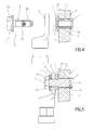
- At least the washer 8 is clipped into a groove 6d (FIG. 5) formed under the head 6a of the screw 6.
- hole 2 might not be through.
- the pod 5 is here independent, it could be in one piece with the ring 4 and its collar.
- the invention is obviously not limited to the setting up of a terminal electrical connection on a rail, the element 3 can be any other element requiring such an electrical connection lug.
Landscapes
- Dowels (AREA)
- Multi-Conductor Connections (AREA)
- Connections Arranged To Contact A Plurality Of Conductors (AREA)
- Connection Of Plates (AREA)
- Clamps And Clips (AREA)
- Connections By Means Of Piercing Elements, Nuts, Or Screws (AREA)
- Processing Of Terminals (AREA)
- Cable Accessories (AREA)
- Coupling Device And Connection With Printed Circuit (AREA)
- Emergency Protection Circuit Devices (AREA)
Abstract
Description
- la figure 1 est une vue en coupe d'une partie du système selon l'invention au cours de la mise en place de la bague et de la douille dans un élément à équiper,
- la figure 2 correspond à la figure 1 après mise en place de la bague et de la douille,
- la figure 3 est une vue en bout du côté de la collerette du système des figures 1 et 2,
- la figure 4 montre l'ensemble de la figure 2 avec en éclaté la vis de fixation et la cosse à fixer.
- la figure 5 est une coupe selon V-V de la figure 3, représentant toutefois le système après fixation de la cosse par la vis sur l'élément.
Claims (5)
- Système de fixation d'une cosse (5) de raccordement électrique sur un élément (3), comportant une bague (1) formée d'une collerette (1b) percée et d'une partie tubulaire (1a) de forme extérieure cylindrique dont l'alésage intérieur est au moins en partie tronconique en s'évasant du côté opposé à ladite collerette et qui est prévue pour être introduite dans un trou (2) cylindrique ménagé dans l'élément (3) à équiper, caractérisé en ce qu'il comporte en outre, d'une part, une douille (4) de forme extérieure tronconique qui est taraudée intérieurement et qui est destinée à être enfilée par sa partie rétrécie dans la bague (1), du côté opposé à sa collerette (1b), et, d'autre part, une vis (6) dont le filetage extérieur de la tige (6b) est conjuguée du filetage intérieur de la douille (4) afin de coopérer entre eux par vissage pour fixer la cosse (5) entre la tête (6a) de la vis (6) et la collerette (1b) de la bague (1).
- Système selon la revendication 1, caractérisé en ce que le taraudage (4a) de la douille (4) est interrompu avant la limite de son extrémité la plus large.
- Système selon l'une des revendications 1 et 2, caractérisé en ce que la collerette (1b) est percée par un orifice (1c) d'un diamètre intérieur légèrement supérieur au diamètre extérieur de la tige (6b) de la vis (6) pour son introduction, mais légèrement inférieur au plus petit diamètre extérieur de la douille (4).
- Système selon l'une des revendications 1 à 3, caractérisé en ce que la vis (6) est pourvue sous sa tête d'une gorge (6d) de retenue pour au moins une rondelle (7,8).
- Système selon la revendication 4, caractérisé en ce que la gorge (6d) de la tige (6b) de la vis (6) est prévue pour recevoir et retenir une rondelle de serrage (7) et une rondelle antifriction (8).
Applications Claiming Priority (2)
| Application Number | Priority Date | Filing Date | Title |
|---|---|---|---|
| FR0207980A FR2841690B1 (fr) | 2002-06-27 | 2002-06-27 | Systeme de fixation d'une cosse de raccordement electrique sur un element |
| FR0207980 | 2002-06-27 |
Publications (2)
| Publication Number | Publication Date |
|---|---|
| EP1376766A1 true EP1376766A1 (fr) | 2004-01-02 |
| EP1376766B1 EP1376766B1 (fr) | 2009-06-03 |
Family
ID=29717113
Family Applications (1)
| Application Number | Title | Priority Date | Filing Date |
|---|---|---|---|
| EP03291510A Expired - Lifetime EP1376766B1 (fr) | 2002-06-27 | 2003-06-20 | Système de fixation d'une cosse de raccordement électrique |
Country Status (5)
| Country | Link |
|---|---|
| EP (1) | EP1376766B1 (fr) |
| AT (1) | ATE433211T1 (fr) |
| DE (1) | DE60327825D1 (fr) |
| ES (1) | ES2324339T3 (fr) |
| FR (1) | FR2841690B1 (fr) |
Cited By (13)
| Publication number | Priority date | Publication date | Assignee | Title |
|---|---|---|---|---|
| WO2007057323A1 (fr) * | 2005-11-15 | 2007-05-24 | Newfrey Llc | Coupleur électriquement conducteur |
| WO2014072228A1 (fr) | 2012-11-12 | 2014-05-15 | Dubuis Et Cie | Dispositif de fixation d'une cosse de raccordement electrique sur un support |
| EP2786843A2 (fr) | 2013-04-02 | 2014-10-08 | Dubuis et Cie S.A.S. | Outil de sertissage alimenté par batterie |
| EP3128617A1 (fr) | 2015-08-04 | 2017-02-08 | Dubuis et Cie | Dispositif pour fixer une borne de connexion électrique à un support |
| EP3179561A1 (fr) | 2015-12-09 | 2017-06-14 | Dubuis et Cie | Dispositif pour fixer une borne de connexion électrique à un support |
| EP3211720A1 (fr) | 2016-02-29 | 2017-08-30 | Dubuis et Cie | Joint de liaison de mise à la terre |
| WO2018206103A1 (fr) | 2017-05-10 | 2018-11-15 | Dubuis Et Cie | Dispositif de fixation d'une borne de connexion électrique à un substrat |
| WO2020015867A1 (fr) * | 2018-07-18 | 2020-01-23 | Fairchild Fasteners Europe - Camloc Gmbh | Insert servant à relier un raccordement électrique à une paroi, outil de démontage et outil d'orientation pour un insert ainsi que procédé de réparation d'un insert |
| WO2020025177A1 (fr) * | 2018-08-03 | 2020-02-06 | Fairchild Fasteners Europe - Camloc Gmbh | Insert pour relier une connexion électrique à un mur et capuchon de protection pour un insert |
| CN114439831A (zh) * | 2020-11-05 | 2022-05-06 | 南京骏威创新精工机械有限公司 | 接地螺母 |
| EP4008482A1 (fr) | 2020-12-07 | 2022-06-08 | Dubuis et Cie | Outil d'assemblage pour assembler un élément déformable sur une pièce à usiner |
| EP4164064A1 (fr) * | 2021-10-08 | 2023-04-12 | TE Connectivity Germany GmbH | Agencement de connexion pour la fixation d'un élément de contact électrique à un conducteur électrique |
| EP4274028A1 (fr) * | 2022-05-06 | 2023-11-08 | Rosenberger Hochfrequenztechnik GmbH & Co. KG | Dispositif de connexion électrique, système de connexion et procédé de réalisation d'une connexion électrique entre deux conducteurs électriques |
Families Citing this family (1)
| Publication number | Priority date | Publication date | Assignee | Title |
|---|---|---|---|---|
| DE102016112782B4 (de) | 2016-07-12 | 2018-05-30 | Fairchild Fasteners Europe - Camloc Gmbh | Einsatz zur Verbindung eines elektrischen Anschlusses mit einer Wand |
Citations (1)
| Publication number | Priority date | Publication date | Assignee | Title |
|---|---|---|---|---|
| DE20102063U1 (de) * | 2000-02-11 | 2001-06-21 | Friedhoff, Sven, 57080 Siegen | Vorrichtung zum Befestigen eines Kabels an einer Bahnschiene |
Family Cites Families (2)
| Publication number | Priority date | Publication date | Assignee | Title |
|---|---|---|---|---|
| FR2692632B1 (fr) * | 1992-06-19 | 1995-12-01 | Dubuis | Insert destine a etre rapporte et fixe dans un element. |
| FR2753752B1 (fr) * | 1996-09-26 | 1998-10-16 | Systeme de fixation d'une cosse de raccordement electrique |
-
2002
- 2002-06-27 FR FR0207980A patent/FR2841690B1/fr not_active Expired - Fee Related
-
2003
- 2003-06-20 EP EP03291510A patent/EP1376766B1/fr not_active Expired - Lifetime
- 2003-06-20 AT AT03291510T patent/ATE433211T1/de not_active IP Right Cessation
- 2003-06-20 ES ES03291510T patent/ES2324339T3/es not_active Expired - Lifetime
- 2003-06-20 DE DE60327825T patent/DE60327825D1/de not_active Expired - Lifetime
Patent Citations (1)
| Publication number | Priority date | Publication date | Assignee | Title |
|---|---|---|---|---|
| DE20102063U1 (de) * | 2000-02-11 | 2001-06-21 | Friedhoff, Sven, 57080 Siegen | Vorrichtung zum Befestigen eines Kabels an einer Bahnschiene |
Cited By (21)
| Publication number | Priority date | Publication date | Assignee | Title |
|---|---|---|---|---|
| WO2007057323A1 (fr) * | 2005-11-15 | 2007-05-24 | Newfrey Llc | Coupleur électriquement conducteur |
| WO2014072228A1 (fr) | 2012-11-12 | 2014-05-15 | Dubuis Et Cie | Dispositif de fixation d'une cosse de raccordement electrique sur un support |
| CN104781988A (zh) * | 2012-11-12 | 2015-07-15 | 杜彼有限公司 | 用于将电气接线端子固定在支承件上的装置 |
| CN104781988B (zh) * | 2012-11-12 | 2018-04-03 | 杜彼有限公司 | 用于将电气接线端子固定在支承件上的装置 |
| EP2786843A2 (fr) | 2013-04-02 | 2014-10-08 | Dubuis et Cie S.A.S. | Outil de sertissage alimenté par batterie |
| EP3128617A1 (fr) | 2015-08-04 | 2017-02-08 | Dubuis et Cie | Dispositif pour fixer une borne de connexion électrique à un support |
| EP3179561A1 (fr) | 2015-12-09 | 2017-06-14 | Dubuis et Cie | Dispositif pour fixer une borne de connexion électrique à un support |
| EP3211720A1 (fr) | 2016-02-29 | 2017-08-30 | Dubuis et Cie | Joint de liaison de mise à la terre |
| WO2017148686A1 (fr) | 2016-02-29 | 2017-09-08 | Dubuis Et Cie | Joint de liaison de mise à la terre |
| WO2018206103A1 (fr) | 2017-05-10 | 2018-11-15 | Dubuis Et Cie | Dispositif de fixation d'une borne de connexion électrique à un substrat |
| WO2020015867A1 (fr) * | 2018-07-18 | 2020-01-23 | Fairchild Fasteners Europe - Camloc Gmbh | Insert servant à relier un raccordement électrique à une paroi, outil de démontage et outil d'orientation pour un insert ainsi que procédé de réparation d'un insert |
| WO2020025177A1 (fr) * | 2018-08-03 | 2020-02-06 | Fairchild Fasteners Europe - Camloc Gmbh | Insert pour relier une connexion électrique à un mur et capuchon de protection pour un insert |
| AU2019314862B2 (en) * | 2018-08-03 | 2022-03-03 | Fairchild Fasteners Europe - Camloc Gmbh | Insert for connecting an electric connection to a wall, and protective cap for an insert |
| US11336063B2 (en) | 2018-08-03 | 2022-05-17 | Fairchild Fasteners Europe—Camloc GmbH | Insert for connecting an electric connection to a wall, and protective cap for an insert |
| CN114439831A (zh) * | 2020-11-05 | 2022-05-06 | 南京骏威创新精工机械有限公司 | 接地螺母 |
| EP4008482A1 (fr) | 2020-12-07 | 2022-06-08 | Dubuis et Cie | Outil d'assemblage pour assembler un élément déformable sur une pièce à usiner |
| EP4164064A1 (fr) * | 2021-10-08 | 2023-04-12 | TE Connectivity Germany GmbH | Agencement de connexion pour la fixation d'un élément de contact électrique à un conducteur électrique |
| CN115966933A (zh) * | 2021-10-08 | 2023-04-14 | 泰连德国有限公司 | 用于将电接触元件紧固到电导体的连接装置 |
| KR20230051103A (ko) * | 2021-10-08 | 2023-04-17 | 티이 커넥티버티 저머니 게엠베하 | 전기 접촉 요소를 전기 전도체에 체결하기 위한 연결 배열체 |
| US12597719B2 (en) | 2021-10-08 | 2026-04-07 | Te Connectivity Germany Gmbh | Connection arrangement for fastening an electrical contact element to an electrical conductor |
| EP4274028A1 (fr) * | 2022-05-06 | 2023-11-08 | Rosenberger Hochfrequenztechnik GmbH & Co. KG | Dispositif de connexion électrique, système de connexion et procédé de réalisation d'une connexion électrique entre deux conducteurs électriques |
Also Published As
| Publication number | Publication date |
|---|---|
| ES2324339T3 (es) | 2009-08-05 |
| ATE433211T1 (de) | 2009-06-15 |
| DE60327825D1 (de) | 2009-07-16 |
| FR2841690B1 (fr) | 2004-11-12 |
| EP1376766B1 (fr) | 2009-06-03 |
| FR2841690A1 (fr) | 2004-01-02 |
Similar Documents
| Publication | Publication Date | Title |
|---|---|---|
| EP1376766B1 (fr) | Système de fixation d'une cosse de raccordement électrique | |
| EP0392927B1 (fr) | Implant vertébral pour dispositif d'ostéosynthèse | |
| FR2761256A1 (fr) | Instrumentation d'osteosynthese rachidienne a connecteur de liaison entre une tige vertebrale et des organes d'ancrage osseux | |
| EP0575259B1 (fr) | Insert destiné à être rapporté dans un élément pour la fixation d'une cosse de raccordement électrique | |
| FR3154465A1 (fr) | Dispositif de fixation démontable de type aveugle, assemblage comportant au moins un tel dispositif de fixation et procédé de démontage d’un tel dispositif de fixation | |
| EP0688063B1 (fr) | Appareil électrique muni d'une borne à vis | |
| EP1929581B1 (fr) | Insert destine a etre rapporte dans un element, pour la fixation et la mise en contact electrique d'une cosse de raccordement electrique | |
| FR2716243A1 (fr) | Insert destiné à être rapport et fixé au travers d'un élément. | |
| FR2653839A1 (fr) | Insert filete. | |
| FR2763654A1 (fr) | Insert pour la fixation d'une cosse de raccordement electrique sur une paroi mince, et ses procedes de montage et de demontage | |
| FR2945590A1 (fr) | Dispositif pour fixer une premiere piece sur une deuxieme piece qui est elle-meme fixee sur une troisieme piece, assemblage de trois pieces en particulier d'un vehicule automobile. | |
| EP2355248A1 (fr) | Serre-fil | |
| EP1141563B1 (fr) | Procede et dispositif pour le blocage anti-rotation d'un ecrou sur une tige filetee | |
| EP2694826A1 (fr) | Dispositif pour assujettir une vis d'assemblage a un element devant etre fixe sur un autre element | |
| FR2770039A1 (fr) | Borne de raccordement electrique et element terminal de tube luminescent la comportant | |
| FR2799312A1 (fr) | Borne de connexion electrique | |
| FR3068591B3 (fr) | Structure de verrouillage rapide d'une vitrine a un profile pour salle de douche | |
| FR2879836A1 (fr) | Dispositif et procede de mise a la masse d'un fil electrique sur une structure metallique, notamment un carter en aluminium pour vehicule automobile | |
| FR2896834A1 (fr) | Dispositif de liaison amovible comportant une agrafe de verrouillage | |
| EP1254391A1 (fr) | Manchon de fixation pour cables optiques | |
| EP1612890B1 (fr) | Pièce de connexion pour un cable électrique, en particulier à moyenne tension | |
| FR2768781A1 (fr) | Ensemble de vis et de mandrin relies l'un a l'autre par un pont secable | |
| FR2685404A1 (fr) | Rivet crante pour assemblage de plaques. | |
| FR3130331A1 (fr) | Boulon polyvalent permettant la mise en place d’un écrou à visser ou d’une bague à sertir depuis une seule extrémité en appliquant une précontrainte | |
| FR2751019A1 (fr) | Dispositif de fixation d'un arret de porte provisoire sur une charniere de vehicule |
Legal Events
| Date | Code | Title | Description |
|---|---|---|---|
| PUAI | Public reference made under article 153(3) epc to a published international application that has entered the european phase |
Free format text: ORIGINAL CODE: 0009012 |
|
| 17P | Request for examination filed |
Effective date: 20031004 |
|
| AK | Designated contracting states |
Kind code of ref document: A1 Designated state(s): AT BE BG CH CY CZ DE DK EE ES FI FR GB GR HU IE IT LI LU MC NL PT RO SE SI SK TR |
|
| AX | Request for extension of the european patent |
Extension state: AL LT LV MK |
|
| AKX | Designation fees paid |
Designated state(s): AT BE BG CH CY CZ DE DK EE ES FI FR GB GR HU IE IT LI LU MC NL PT RO SE SI SK TR |
|
| GRAP | Despatch of communication of intention to grant a patent |
Free format text: ORIGINAL CODE: EPIDOSNIGR1 |
|
| RIN1 | Information on inventor provided before grant (corrected) |
Inventor name: GASSELIN, BENOIT |
|
| GRAS | Grant fee paid |
Free format text: ORIGINAL CODE: EPIDOSNIGR3 |
|
| GRAA | (expected) grant |
Free format text: ORIGINAL CODE: 0009210 |
|
| AK | Designated contracting states |
Kind code of ref document: B1 Designated state(s): AT BE BG CH CY CZ DE DK EE ES FI FR GB GR HU IE IT LI LU MC NL PT RO SE SI SK TR |
|
| REG | Reference to a national code |
Ref country code: GB Ref legal event code: FG4D Free format text: NOT ENGLISH |
|
| REG | Reference to a national code |
Ref country code: CH Ref legal event code: EP |
|
| REG | Reference to a national code |
Ref country code: IE Ref legal event code: FG4D Free format text: LANGUAGE OF EP DOCUMENT: FRENCH |
|
| REF | Corresponds to: |
Ref document number: 60327825 Country of ref document: DE Date of ref document: 20090716 Kind code of ref document: P |
|
| REG | Reference to a national code |
Ref country code: ES Ref legal event code: FG2A Ref document number: 2324339 Country of ref document: ES Kind code of ref document: T3 |
|
| PG25 | Lapsed in a contracting state [announced via postgrant information from national office to epo] |
Ref country code: FI Free format text: LAPSE BECAUSE OF FAILURE TO SUBMIT A TRANSLATION OF THE DESCRIPTION OR TO PAY THE FEE WITHIN THE PRESCRIBED TIME-LIMIT Effective date: 20090603 Ref country code: AT Free format text: LAPSE BECAUSE OF FAILURE TO SUBMIT A TRANSLATION OF THE DESCRIPTION OR TO PAY THE FEE WITHIN THE PRESCRIBED TIME-LIMIT Effective date: 20090603 |
|
| NLV1 | Nl: lapsed or annulled due to failure to fulfill the requirements of art. 29p and 29m of the patents act | ||
| PG25 | Lapsed in a contracting state [announced via postgrant information from national office to epo] |
Ref country code: SI Free format text: LAPSE BECAUSE OF FAILURE TO SUBMIT A TRANSLATION OF THE DESCRIPTION OR TO PAY THE FEE WITHIN THE PRESCRIBED TIME-LIMIT Effective date: 20090603 Ref country code: NL Free format text: LAPSE BECAUSE OF FAILURE TO SUBMIT A TRANSLATION OF THE DESCRIPTION OR TO PAY THE FEE WITHIN THE PRESCRIBED TIME-LIMIT Effective date: 20090603 Ref country code: SE Free format text: LAPSE BECAUSE OF FAILURE TO SUBMIT A TRANSLATION OF THE DESCRIPTION OR TO PAY THE FEE WITHIN THE PRESCRIBED TIME-LIMIT Effective date: 20090903 |
|
| BERE | Be: lapsed |
Owner name: M. DUBUIS ET CIE Effective date: 20090630 |
|
| REG | Reference to a national code |
Ref country code: IE Ref legal event code: FD4D |
|
| PG25 | Lapsed in a contracting state [announced via postgrant information from national office to epo] |
Ref country code: CZ Free format text: LAPSE BECAUSE OF FAILURE TO SUBMIT A TRANSLATION OF THE DESCRIPTION OR TO PAY THE FEE WITHIN THE PRESCRIBED TIME-LIMIT Effective date: 20090603 Ref country code: IE Free format text: LAPSE BECAUSE OF FAILURE TO SUBMIT A TRANSLATION OF THE DESCRIPTION OR TO PAY THE FEE WITHIN THE PRESCRIBED TIME-LIMIT Effective date: 20090603 Ref country code: MC Free format text: LAPSE BECAUSE OF NON-PAYMENT OF DUE FEES Effective date: 20090630 Ref country code: EE Free format text: LAPSE BECAUSE OF FAILURE TO SUBMIT A TRANSLATION OF THE DESCRIPTION OR TO PAY THE FEE WITHIN THE PRESCRIBED TIME-LIMIT Effective date: 20090603 Ref country code: RO Free format text: LAPSE BECAUSE OF FAILURE TO SUBMIT A TRANSLATION OF THE DESCRIPTION OR TO PAY THE FEE WITHIN THE PRESCRIBED TIME-LIMIT Effective date: 20090603 |
|
| REG | Reference to a national code |
Ref country code: CH Ref legal event code: PL |
|
| PG25 | Lapsed in a contracting state [announced via postgrant information from national office to epo] |
Ref country code: SK Free format text: LAPSE BECAUSE OF FAILURE TO SUBMIT A TRANSLATION OF THE DESCRIPTION OR TO PAY THE FEE WITHIN THE PRESCRIBED TIME-LIMIT Effective date: 20090603 |
|
| PG25 | Lapsed in a contracting state [announced via postgrant information from national office to epo] |
Ref country code: BG Free format text: LAPSE BECAUSE OF FAILURE TO SUBMIT A TRANSLATION OF THE DESCRIPTION OR TO PAY THE FEE WITHIN THE PRESCRIBED TIME-LIMIT Effective date: 20090903 Ref country code: PT Free format text: LAPSE BECAUSE OF FAILURE TO SUBMIT A TRANSLATION OF THE DESCRIPTION OR TO PAY THE FEE WITHIN THE PRESCRIBED TIME-LIMIT Effective date: 20091003 |
|
| PLBE | No opposition filed within time limit |
Free format text: ORIGINAL CODE: 0009261 |
|
| STAA | Information on the status of an ep patent application or granted ep patent |
Free format text: STATUS: NO OPPOSITION FILED WITHIN TIME LIMIT |
|
| PG25 | Lapsed in a contracting state [announced via postgrant information from national office to epo] |
Ref country code: DK Free format text: LAPSE BECAUSE OF FAILURE TO SUBMIT A TRANSLATION OF THE DESCRIPTION OR TO PAY THE FEE WITHIN THE PRESCRIBED TIME-LIMIT Effective date: 20090603 Ref country code: LI Free format text: LAPSE BECAUSE OF NON-PAYMENT OF DUE FEES Effective date: 20090630 Ref country code: CH Free format text: LAPSE BECAUSE OF NON-PAYMENT OF DUE FEES Effective date: 20090630 |
|
| 26N | No opposition filed |
Effective date: 20100304 |
|
| PG25 | Lapsed in a contracting state [announced via postgrant information from national office to epo] |
Ref country code: BE Free format text: LAPSE BECAUSE OF NON-PAYMENT OF DUE FEES Effective date: 20090630 |
|
| PG25 | Lapsed in a contracting state [announced via postgrant information from national office to epo] |
Ref country code: GR Free format text: LAPSE BECAUSE OF FAILURE TO SUBMIT A TRANSLATION OF THE DESCRIPTION OR TO PAY THE FEE WITHIN THE PRESCRIBED TIME-LIMIT Effective date: 20090904 |
|
| PG25 | Lapsed in a contracting state [announced via postgrant information from national office to epo] |
Ref country code: LU Free format text: LAPSE BECAUSE OF NON-PAYMENT OF DUE FEES Effective date: 20090620 |
|
| PG25 | Lapsed in a contracting state [announced via postgrant information from national office to epo] |
Ref country code: HU Free format text: LAPSE BECAUSE OF FAILURE TO SUBMIT A TRANSLATION OF THE DESCRIPTION OR TO PAY THE FEE WITHIN THE PRESCRIBED TIME-LIMIT Effective date: 20091204 |
|
| PG25 | Lapsed in a contracting state [announced via postgrant information from national office to epo] |
Ref country code: TR Free format text: LAPSE BECAUSE OF FAILURE TO SUBMIT A TRANSLATION OF THE DESCRIPTION OR TO PAY THE FEE WITHIN THE PRESCRIBED TIME-LIMIT Effective date: 20090603 |
|
| PG25 | Lapsed in a contracting state [announced via postgrant information from national office to epo] |
Ref country code: CY Free format text: LAPSE BECAUSE OF FAILURE TO SUBMIT A TRANSLATION OF THE DESCRIPTION OR TO PAY THE FEE WITHIN THE PRESCRIBED TIME-LIMIT Effective date: 20090603 |
|
| REG | Reference to a national code |
Ref country code: FR Ref legal event code: PLFP Year of fee payment: 13 |
|
| REG | Reference to a national code |
Ref country code: FR Ref legal event code: PLFP Year of fee payment: 14 |
|
| PGFP | Annual fee paid to national office [announced via postgrant information from national office to epo] |
Ref country code: DE Payment date: 20160614 Year of fee payment: 14 Ref country code: ES Payment date: 20160511 Year of fee payment: 14 Ref country code: GB Payment date: 20160615 Year of fee payment: 14 |
|
| PGFP | Annual fee paid to national office [announced via postgrant information from national office to epo] |
Ref country code: IT Payment date: 20160621 Year of fee payment: 14 |
|
| REG | Reference to a national code |
Ref country code: FR Ref legal event code: PLFP Year of fee payment: 15 |
|
| PGFP | Annual fee paid to national office [announced via postgrant information from national office to epo] |
Ref country code: FR Payment date: 20170511 Year of fee payment: 15 |
|
| REG | Reference to a national code |
Ref country code: DE Ref legal event code: R119 Ref document number: 60327825 Country of ref document: DE |
|
| GBPC | Gb: european patent ceased through non-payment of renewal fee |
Effective date: 20170620 |
|
| PG25 | Lapsed in a contracting state [announced via postgrant information from national office to epo] |
Ref country code: GB Free format text: LAPSE BECAUSE OF NON-PAYMENT OF DUE FEES Effective date: 20170620 Ref country code: DE Free format text: LAPSE BECAUSE OF NON-PAYMENT OF DUE FEES Effective date: 20180103 |
|
| PG25 | Lapsed in a contracting state [announced via postgrant information from national office to epo] |
Ref country code: IT Free format text: LAPSE BECAUSE OF NON-PAYMENT OF DUE FEES Effective date: 20170620 |
|
| REG | Reference to a national code |
Ref country code: ES Ref legal event code: FD2A Effective date: 20181107 |
|
| PG25 | Lapsed in a contracting state [announced via postgrant information from national office to epo] |
Ref country code: ES Free format text: LAPSE BECAUSE OF NON-PAYMENT OF DUE FEES Effective date: 20170621 |
|
| PG25 | Lapsed in a contracting state [announced via postgrant information from national office to epo] |
Ref country code: FR Free format text: LAPSE BECAUSE OF NON-PAYMENT OF DUE FEES Effective date: 20180630 |