EP1376733A2 - Cooling device for battery power source - Google Patents
Cooling device for battery power source Download PDFInfo
- Publication number
- EP1376733A2 EP1376733A2 EP20030016665 EP03016665A EP1376733A2 EP 1376733 A2 EP1376733 A2 EP 1376733A2 EP 20030016665 EP20030016665 EP 20030016665 EP 03016665 A EP03016665 A EP 03016665A EP 1376733 A2 EP1376733 A2 EP 1376733A2
- Authority
- EP
- European Patent Office
- Prior art keywords
- air
- power source
- holder casing
- battery power
- battery modules
- Prior art date
- Legal status (The legal status is an assumption and is not a legal conclusion. Google has not performed a legal analysis and makes no representation as to the accuracy of the status listed.)
- Withdrawn
Links
Images


Classifications
-
- H—ELECTRICITY
- H01—ELECTRIC ELEMENTS
- H01M—PROCESSES OR MEANS, e.g. BATTERIES, FOR THE DIRECT CONVERSION OF CHEMICAL ENERGY INTO ELECTRICAL ENERGY
- H01M50/00—Constructional details or processes of manufacture of the non-active parts of electrochemical cells other than fuel cells, e.g. hybrid cells
- H01M50/20—Mountings; Secondary casings or frames; Racks, modules or packs; Suspension devices; Shock absorbers; Transport or carrying devices; Holders
- H01M50/218—Mountings; Secondary casings or frames; Racks, modules or packs; Suspension devices; Shock absorbers; Transport or carrying devices; Holders characterised by the material
- H01M50/22—Mountings; Secondary casings or frames; Racks, modules or packs; Suspension devices; Shock absorbers; Transport or carrying devices; Holders characterised by the material of the casings or racks
- H01M50/227—Organic material
-
- H—ELECTRICITY
- H01—ELECTRIC ELEMENTS
- H01M—PROCESSES OR MEANS, e.g. BATTERIES, FOR THE DIRECT CONVERSION OF CHEMICAL ENERGY INTO ELECTRICAL ENERGY
- H01M10/00—Secondary cells; Manufacture thereof
- H01M10/60—Heating or cooling; Temperature control
- H01M10/65—Means for temperature control structurally associated with the cells
- H01M10/656—Means for temperature control structurally associated with the cells characterised by the type of heat-exchange fluid
- H01M10/6561—Gases
- H01M10/6563—Gases with forced flow, e.g. by blowers
-
- H—ELECTRICITY
- H01—ELECTRIC ELEMENTS
- H01M—PROCESSES OR MEANS, e.g. BATTERIES, FOR THE DIRECT CONVERSION OF CHEMICAL ENERGY INTO ELECTRICAL ENERGY
- H01M10/00—Secondary cells; Manufacture thereof
- H01M10/60—Heating or cooling; Temperature control
- H01M10/61—Types of temperature control
- H01M10/613—Cooling or keeping cold
-
- H—ELECTRICITY
- H01—ELECTRIC ELEMENTS
- H01M—PROCESSES OR MEANS, e.g. BATTERIES, FOR THE DIRECT CONVERSION OF CHEMICAL ENERGY INTO ELECTRICAL ENERGY
- H01M10/00—Secondary cells; Manufacture thereof
- H01M10/60—Heating or cooling; Temperature control
- H01M10/65—Means for temperature control structurally associated with the cells
- H01M10/651—Means for temperature control structurally associated with the cells characterised by parameters specified by a numeric value or mathematical formula, e.g. ratios, sizes or concentrations
- H01M10/652—Means for temperature control structurally associated with the cells characterised by parameters specified by a numeric value or mathematical formula, e.g. ratios, sizes or concentrations characterised by gradients
-
- H—ELECTRICITY
- H01—ELECTRIC ELEMENTS
- H01M—PROCESSES OR MEANS, e.g. BATTERIES, FOR THE DIRECT CONVERSION OF CHEMICAL ENERGY INTO ELECTRICAL ENERGY
- H01M10/00—Secondary cells; Manufacture thereof
- H01M10/60—Heating or cooling; Temperature control
- H01M10/65—Means for temperature control structurally associated with the cells
- H01M10/655—Solid structures for heat exchange or heat conduction
- H01M10/6556—Solid parts with flow channel passages or pipes for heat exchange
- H01M10/6557—Solid parts with flow channel passages or pipes for heat exchange arranged between the cells
-
- H—ELECTRICITY
- H01—ELECTRIC ELEMENTS
- H01M—PROCESSES OR MEANS, e.g. BATTERIES, FOR THE DIRECT CONVERSION OF CHEMICAL ENERGY INTO ELECTRICAL ENERGY
- H01M10/00—Secondary cells; Manufacture thereof
- H01M10/60—Heating or cooling; Temperature control
- H01M10/65—Means for temperature control structurally associated with the cells
- H01M10/656—Means for temperature control structurally associated with the cells characterised by the type of heat-exchange fluid
- H01M10/6561—Gases
- H01M10/6566—Means within the gas flow to guide the flow around one or more cells, e.g. manifolds, baffles or other barriers
-
- H—ELECTRICITY
- H01—ELECTRIC ELEMENTS
- H01M—PROCESSES OR MEANS, e.g. BATTERIES, FOR THE DIRECT CONVERSION OF CHEMICAL ENERGY INTO ELECTRICAL ENERGY
- H01M50/00—Constructional details or processes of manufacture of the non-active parts of electrochemical cells other than fuel cells, e.g. hybrid cells
- H01M50/20—Mountings; Secondary casings or frames; Racks, modules or packs; Suspension devices; Shock absorbers; Transport or carrying devices; Holders
- H01M50/204—Racks, modules or packs for multiple batteries or multiple cells
- H01M50/207—Racks, modules or packs for multiple batteries or multiple cells characterised by their shape
- H01M50/213—Racks, modules or packs for multiple batteries or multiple cells characterised by their shape adapted for cells having curved cross-section, e.g. round or elliptic
-
- H—ELECTRICITY
- H01—ELECTRIC ELEMENTS
- H01M—PROCESSES OR MEANS, e.g. BATTERIES, FOR THE DIRECT CONVERSION OF CHEMICAL ENERGY INTO ELECTRICAL ENERGY
- H01M50/00—Constructional details or processes of manufacture of the non-active parts of electrochemical cells other than fuel cells, e.g. hybrid cells
- H01M50/50—Current conducting connections for cells or batteries
- H01M50/502—Interconnectors for connecting terminals of adjacent batteries; Interconnectors for connecting cells outside a battery casing
- H01M50/505—Interconnectors for connecting terminals of adjacent batteries; Interconnectors for connecting cells outside a battery casing comprising a single busbar
-
- H—ELECTRICITY
- H01—ELECTRIC ELEMENTS
- H01M—PROCESSES OR MEANS, e.g. BATTERIES, FOR THE DIRECT CONVERSION OF CHEMICAL ENERGY INTO ELECTRICAL ENERGY
- H01M50/00—Constructional details or processes of manufacture of the non-active parts of electrochemical cells other than fuel cells, e.g. hybrid cells
- H01M50/50—Current conducting connections for cells or batteries
- H01M50/502—Interconnectors for connecting terminals of adjacent batteries; Interconnectors for connecting cells outside a battery casing
- H01M50/509—Interconnectors for connecting terminals of adjacent batteries; Interconnectors for connecting cells outside a battery casing characterised by the type of connection, e.g. mixed connections
- H01M50/51—Connection only in series
-
- H—ELECTRICITY
- H01—ELECTRIC ELEMENTS
- H01M—PROCESSES OR MEANS, e.g. BATTERIES, FOR THE DIRECT CONVERSION OF CHEMICAL ENERGY INTO ELECTRICAL ENERGY
- H01M50/00—Constructional details or processes of manufacture of the non-active parts of electrochemical cells other than fuel cells, e.g. hybrid cells
- H01M50/50—Current conducting connections for cells or batteries
- H01M50/502—Interconnectors for connecting terminals of adjacent batteries; Interconnectors for connecting cells outside a battery casing
- H01M50/514—Methods for interconnecting adjacent batteries or cells
- H01M50/516—Methods for interconnecting adjacent batteries or cells by welding, soldering or brazing
-
- H—ELECTRICITY
- H01—ELECTRIC ELEMENTS
- H01M—PROCESSES OR MEANS, e.g. BATTERIES, FOR THE DIRECT CONVERSION OF CHEMICAL ENERGY INTO ELECTRICAL ENERGY
- H01M50/00—Constructional details or processes of manufacture of the non-active parts of electrochemical cells other than fuel cells, e.g. hybrid cells
- H01M50/50—Current conducting connections for cells or batteries
- H01M50/569—Constructional details of current conducting connections for detecting conditions inside cells or batteries, e.g. details of voltage sensing terminals
-
- H—ELECTRICITY
- H01—ELECTRIC ELEMENTS
- H01M—PROCESSES OR MEANS, e.g. BATTERIES, FOR THE DIRECT CONVERSION OF CHEMICAL ENERGY INTO ELECTRICAL ENERGY
- H01M10/00—Secondary cells; Manufacture thereof
- H01M10/60—Heating or cooling; Temperature control
- H01M10/62—Heating or cooling; Temperature control specially adapted for specific applications
- H01M10/625—Vehicles
-
- H—ELECTRICITY
- H01—ELECTRIC ELEMENTS
- H01M—PROCESSES OR MEANS, e.g. BATTERIES, FOR THE DIRECT CONVERSION OF CHEMICAL ENERGY INTO ELECTRICAL ENERGY
- H01M10/00—Secondary cells; Manufacture thereof
- H01M10/60—Heating or cooling; Temperature control
- H01M10/64—Heating or cooling; Temperature control characterised by the shape of the cells
- H01M10/643—Cylindrical cells
-
- Y—GENERAL TAGGING OF NEW TECHNOLOGICAL DEVELOPMENTS; GENERAL TAGGING OF CROSS-SECTIONAL TECHNOLOGIES SPANNING OVER SEVERAL SECTIONS OF THE IPC; TECHNICAL SUBJECTS COVERED BY FORMER USPC CROSS-REFERENCE ART COLLECTIONS [XRACs] AND DIGESTS
- Y02—TECHNOLOGIES OR APPLICATIONS FOR MITIGATION OR ADAPTATION AGAINST CLIMATE CHANGE
- Y02E—REDUCTION OF GREENHOUSE GAS [GHG] EMISSIONS, RELATED TO ENERGY GENERATION, TRANSMISSION OR DISTRIBUTION
- Y02E60/00—Enabling technologies; Technologies with a potential or indirect contribution to GHG emissions mitigation
- Y02E60/10—Energy storage using batteries
Abstract
Description
- The present invention relates to a battery power source device, used as a motor drive source or the like for an electrically powered automobile, comprising a cooling device that cools this battery power source device by air cooling.
- In a known type of battery power source of this kind, a large number of battery modules constituted by connecting electrically and mechanically in series a row consisting of a plurality of single cells are arranged in parallel and held in a holder casing. High voltage power is extracted by connecting these battery modules electrically in series.
- The present inventors developed a battery power source device wherein a large number of battery modules are arranged in parallel in a holder casing comprising a main casing body and two end plates, series electrical connection between the battery modules being achieved by holding ends of the battery modules in holding apertures provided in the end plates and locking the ends of the battery modules to a metal bus bar arranged on the outside face of the end plates.
- However, with this prior example, there was the serious problem of how to restrain the rise in temperature produced by evolution of heat from the battery modules tightly packed in the holder casing.
- Also, an arrangement is known in which high voltage power is supplied in an electrically powered automobile by mounting therein battery power source assemblies comprising a pair of battery power source devices electrically connected in series. However, in this case, efficient cooling of the battery power source devices presented a serious problem.
- In order to suppress rising temperature brought about by evolution of heat from the batteries in the above battery power source device, the inventors modified the design of the holder casing and developed a cooling device having an air flow guide such as to make a suitable amount of cooling air flow along the battery modules.
- However, with this prior example, not only was it difficult to suitably distribute the flow of air in regard to the battery modules but also it was difficult to effect uniform cooling between the single cells connected in series to constitute the individual battery modules. specifically, the air flowing along the battery modules rises in temperature due to the heat received from the single cells whilst it is flowing from the upstream side to the downstream side, causing its cooling effect to gradually diminish. Thus it was extremely difficult to compensate for this by individually controlling the air flow rate and air flow speed for each individual battery module in order to achieve uniform cooling of the individual unit cells from the upstream side to the downstream side.
- A main object of the present invention is therefore to solve the problems of the prior examples and to provide a cooling device of a comparatively simple structure whereby cooling of a battery power source assembly comprising a pair of battery power source devices can be achieved in an efficient manner.
- In order to solve the above problems, according to the present invention, a battery power source comprising a cooling device and a large number of battery modules constituted by a plurality of single cells connected in a row electrically and mechanically in series, arranged parallel to each other and held in a holder casing, wherein air is forcibly made to flow in one direction within this holder casing thereby cooling the large number of battery modules in the holder casing the direction of flow of the air is a direction at right angles to the longitudinal direction of the battery modules, and wherein means for flow alignment are arranged within the holder casing such that the flow speed of the air flowing through the holder casing is faster on the downstream side than on the upstream side.
- Preferably, at a location on the downstream side in the holder casing, the flow path area is progressively diminished such that the flow speed of air flowing through the holder casing gradually becomes larger in the direction of flow of the air.
- By adopting such a construction, the flow speed of the air flowing from the upstream side to the downstream side can be gradually increased, so that the cooling effect is raised practically in proportion to the square root of the flow speed, so it is possible to compensate for the diminution of cooling effect brought about by the rise in temperature of the air occurring whilst it flows from the upstream side to the downstream side, so that all the battery modules are subjected to practically uniform cooling.
- According to the invention a construction may be adopted wherein, a battery power source comprising a cooling device and a large number of battery modules constituted by a plurality of single cells connected in a row electrically and mechanically in series, arranged parallel to each other and held in a holder casing, wherein air is forcibly made to flow in one direction within this holder casing thereby cooling the large number of battery modules in the holder casing the direction of flow of the air is a direction at right angles to the longitudinal direction of the battery modules, and wherein means for flow alignment are arranged within the holder casing such that the flow speed of the air flowing through the holder casing is faster on the downstream side than on the upstream side, and wherein means for screening are arranged only at a location on the upstream side within the holder casing such that the area of the battery modules that is exposed to the air flowing through the holder casing becomes larger going in the direction in which air is flowing.
- By means of a such a construction, overcooling of battery modules on the upstream side is prevented and the air flow can be efficiently utilised for cooling of the battery modules of the entire battery power source device and also more air can be brought into contact with the battery modules on the downstream side than with those on the upstream side so the lowering of cooling effect due to rise in temperature of the air occurring between the upstream side and the downstream side can be compensated for, making it possible to achieve practically uniform cooling of all the battery modules.
- Thus by combining means for flow alignment and means for screening as described above, uniform cooling of the battery modules of the entire battery power source device can easily be achieved.
- In order to solve the above problems the present invention provides a battery power source comprising a cooling device and a pair of left and right battery power source devices constituted by holding a large number of battery modules consisting of a plurality of single cells connected in a row electrically and mechanically in series arranged horizontally and parallel to each other in a holder casing, respective air supply chambers being formed below these holder casings wherein air is fed to a lower aperture of the holder casing of the respective battery power source devices through left and right air supply chambers from a pressure-feed fan so that the battery module is cooled by the air current that is discharged from an upper aperture after rising through the holder casings wherein the pressure-feed fan has two blowing ports that supply air in the direction parallel to the end plates into the respective battery power source devices, these blowing ports opening an positions close to a respective one end plate of the battery power source devices, the bottom faces of the air supply chambers being formed with a slope whereby the cross-sectional area of the flow path gradually diminishes from the one end plate side towards the other end plate side, and wherein the flow path gradually diminishes from the one end plate side towards the other end plate side, and wherein means for flow alignment are arranged within the ladder casing whereby the flow rate of the air flowing within the ladder casing is faster at the upper than at the lower side.
- With the above invention, delivery of air into the left and right battery power source device can be achieved with a single pressure-feed type fan and, due to the provision of the slope, variation of the amount of air that is taken into the holder casing from the air supply chamber depending on the position in the direction from one end plate towards the other end plate in each battery power source device can be prevented.
- According to the invention a battery power source comprising a cooling device and a pair of left and right battery power source devices constituted by holding a large number of battery modules consisting of a plurality of single cells connected in a row electrically and mechanically in series arranged horizontally and parallel to each other in a holder casing, respective air supply chambers being formed below said holder casing wherein air is fed to a lower aperture of the holder casing of the respective battery power source devices through left and right air supply chambers from a pressure-feed fan that the battery module is cooled by the air current that is discharged from an upper aperture after rising through said holder casings wherein the pressure-feed fan has two blowing ports that supply air in the direction parallel to the end plates into said respective battery power source devices, these blowing ports opening in positions close to a respective one end plate of the battery power source devices, the bottom faces of the air supply chambers being formed with a slope whereby the cross-sectional area of the flow path gradually diminishes from the one end plate side towards the other end plate side, and wherein means for screening are arranged in the holder casing whereby the area of the battery modules that is exposed to the air flowing through said holder casing is greater in the upper part than in the lower part.
- Preferably means for screening are arranged only in a location of the bottom part in the holder casing, the means for screening being constructed such that the area of the battery modules that is exposed to the air flowing through the holder casing gradually gets larger in the direction of flow of the air.
- By means of the above construction, due to the action of the means for flow alignment and means for screening, cooling of the large number of battery modules within the battery power source devices can be performed uniformly and without bias in the vertical direction. As a result, uniform cooling of all the battery modules in the two battery power source devices can be achieved.
- These and other objects, features and advantages of the present invention will be apparent from the following description of the preferred embodiments of the invention in conjunction with the accompanying drawings, in which:
- Fig. 1 is a diagrammatic side view showing the relationship between an automobile and a battery pack unit;
- Fig. 2 is a perspective view showing an outline of a battery pack unit;
- Fig. 3 is a perspective view showing a battery power source assembly;
- Fig. 4 is a front view showing a battery module, Fig. 4B is a left side view thereof, and Fig. 4C is a right side view thereof;
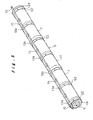
- Fig. 5 is a perspective view of a battery module in which an outer tube is shown by an imaginary line;
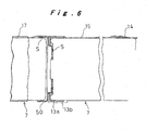
- Fig. 6 is a cross-sectional view with part broken away showing major parts of a battery module;
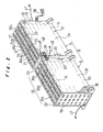
- Fig. 7 is an exploded perspective view of a battery power source device;
- Fig. 8 is a cross-sectional view showing a battery power source device;
- Fig. 9 is a cross-sectional view to a larger scale showing major parts of a battery power source device;
- Fig. 10 is a front view of a first end plate seen from the side of the inner surface;
- Fig. 11A is a cross-sectional view to a larger scale along the line A-A of Fig. 10 and Fig. 11B is a front view thereof;
- Fig. 12 is a cross-sectional view to a larger scale along the line B-B of Fig. 10;
- Fig. 13 is a front view of a second end plate seen from the side of the outer surface;
- Fig. 14 is a cross-sectional view to a larger scale along the line C-C of Fig. 13;
- Fig. 15 is a diagram showing how a battery module is connected;
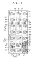
- Fig. 16 is a diagram showing how a PTC sensor is connected;
- Fig. 17 is a cross-sectional view of a battery pack unit; and
- Fig. 18 is an exploded perspective view of a battery pack unit.
-
- Fig. 1 shows a hybrid type automobile whose locomotive drive source is constituted by combining an internal combustion engine and a battery driven motor. In this hybrid type automobile, the internal combustion engine is operated under optimum conditions and when output is insufficient for the running conditions, this output deficiency is made up by the output of the battery driven motor; and by performing regenerative power absorption during deceleration the distance of travel per unit of fuel is enormously increased in comparison with an automobile in which an ordinary internal combustion engine is used on its own.
- As the electric power source of the battery driven motor, nickel-hydrogen secondary cells are employed, these being accommodated in a battery pack unit 1 shown in Fig. 1 and Fig. 2. This battery pack unit 1 is arranged in the space between the
rear seat 2 and theboot 3 behind it. - Battery pack unit 1 comprises an
outside casing 4 consisting of a resin moulding, afan 5 arranged therein, and a pair of left and right batterypower source devices outer casing 4. In each batterypower source device 6, there are provided 126 electrically series-connected single cells (also called battery cells) constituted by nickel-hydrogen secondary cell units; this enables power supply of voltage about 125 V. Left and right batterypower source devices power source assembly 8, which is capable of supplying power of voltage about 250 V. - Specifically power of voltage about 250 V is supplied to the battery driven motor.
- Fig. 3 shows a battery
power source assembly 8 constituted of a left and right pair of batterypower source devices - Each battery
power source device 6 is constructed by holding within aholder casing 10 a total of 21battery modules 9 arranged in parallel in three rows transversely and seven rows vertically, each module being constituted by connecting electrically and mechanically in series a row of sixsingle cells 7. - As shown in Fig. 4, Fig. 5 and Fig. 6, in a
battery module 9, series connection is effected betweensingle cells 7 using spot welds S, by means ofmetal connecting rings 50. Also,square nuts 11 provided with seats ha are connected tosingle cells 7 at the plus electrode end using spot welding by means of connectingrings 50, at the plus electrode end ofbattery module 9. Furthermore,hexagonal nuts 12 are connected tosingle cells 7 at the minus electrode end using spot welding by means of connectingrings 50 at the minus electrode end ofbattery module 9. The dimension between the opposite sides ofsquare nut 11 and the dimension between the opposite sides ofhexagonal nut 12 are made the same so that there is no possibility of thesenuts square holding recess 30a or ahexagonal holding recess 30b, to be described. Insulatingrings insulating rings insulating rings - A PTC (Positive Temperature Coefficient)
sensor 14 is connected to the side circumferential face of eachsingle cell 7. This PTC sensor is a temperature sensor in which abnormality is detected by an abrupt increase of electrical resistance which occurs when the temperature of asingle cell 7 rises due to some internal abnormality. For example a sensor may be employed whose electrical resistance rises abruptly when a temperature of 80°C is reached. A PTC sensor may also be called a "poly sensor". Sensors other than PTC sensors may of course be used forsuch temperature sensor 14. SixPTC sensors 14 are connected in series by connectingwire 15, and aterminal element 16 consisting of bendable metal plate is mounted at both ends of these. The twoterminal elements battery module 9. - The outer peripheral surface of
battery module 9 is covered by means of anouter tube 17 made of resin such as polyvinyl chloride having electrical insulation and heat shrinkage properties.PTC sensor 14 and its connectingwire 15 are protected bysingle cell 7 andouter tube 17.Square nut 11 constituting the plus electrode,hexagonal nut 12 constituting the minus electrode and the twoterminal elements outer tube 17. - As shown in Fig. 3, Fig. 7 and Fig. 8, holder casing is chiefly constituted by
main casing body 18,first end plate 19,second end plate 20, three coolingfin plates anti-vibration rubber sheets -
Main casing body 18 consists of a unitary resin moulding formed in the shape of a cuboidal box whose upper and lower faces are open. Thespace 26 formed within the twoend walls side walls spaces partitions end walls fin plates 21 are inserted from above so as to be positioned in the middle respectively of firstpartitioned space 26a on the side nearest thesecond end plate 20, secondpartitioned space 26b in the middle, and thirdpartitioned space 26c on the side nearestfirst end plate 19, being arranged parallel to the twoend walls main casing body 18. - A total of 21
insertion apertures end walls partitions cooling fin plates insertion apertures battery modules 9. -
First end plate 19 is screw-fixed to endwall 23 at one end ofmain casing body 18, by utilising screw holes 70 at its four corners. 27 is a frame part formed at the periphery ofend wall 23 ofmain casing body 18 as to receivefirst end plate 19 fitting within it.Second end plate 20 is releasably held onend wall 23 at the other end ofmain casing body 18. Specifically, second end plate is held fitted in a movable condition on aframe 27 formed at the other end ofmain casing body 18. - As shown in Fig. 7 ~ Fig. 12,
first end plate 19 is constituted by a resin plate and has abus bar 28 embedded and fixed in this resin plate by insertion moulding. On theinside face 29 of the resin plate there are provided square-shaped holding recesses 30a for holding, fitted therein, thesquare nut 11 constituting the plus electrode terminal of abattery module 9 and hexagonal-shaped holding recesses 30b for holding, fitted therein, thehexagonal nut 12 constituting the minus electrode terminal of abattery module 9. These holdingrecesses insertion apertures recess holding recess 30a while the other is a minus-side hexagonal-shapedholding recess 30b. Holdingrecesses nuts battery module 9 fit thereinto, sosquare nut 11 can only be held insquare holding recess 30a and the possibility of its being accidentally held inhexagonal holding recess 30b can be forestalled. - A total of 21
locking recesses outside face 31 offirst end plate 19 in positions corresponding to holdingrecesses recesses recesses 32a are of exactly the same shape as square holdingrecesses 30a described above and hexagonal locking recesses 32b are of exactly the same shape as hexagonal holding recesses 30b described above. As shown in Fig. 10, ahexagonal locking recess 32b is provided behind square holdingrecess 30a and asquare locking recess 32a is provided behindhexagonal holding recess 30b, respectively. The purpose of this construction is to make it possible to use in common respective identicalfirst end plates power source devices power source assembly 8 as shown in Fig. 3. When a left-side batterypower source device 6 is employed,first end plate 19 is assembled intomain casing body 18 in a condition as described above but, when a right-side batterypower source device 6 is employed,first end plate 19 is assembled intomain casing body 18 with recesses corresponding to lockingrecesses recesses - Metal bus bars 28 that effect electrical connection between the terminals of
battery modules 9 are embedded and fixed by insertion moulding such as to be positioned in the middle in the thickness direction of the resin plate offirst end plate 19. Bus bars 28 are exposed to the outside at portions surrounded by holdingrecesses recesses - Through-
holes 33 are provided in the middle of such exposed portions. -
Nuts battery module 9, in a condition in which they are held fitted into holdingrecesses hole 33 from the side of lockingrecesses bolts 34,nuts bus bar 28. Sincesquare nut 11 that constitutes the plus electrode ofbattery module 9 is held fitted into the plus-side square holdingrecess 30a without any possibility of confusion, the plus electrode ofbattery module 9 is reliably connected to the plus portion ofbus bar 28. Likewise,hexagonal nut 12 constituting the minus electrode ofbattery module 9 is held fitted in, without any possibility of confusion1 in the minus-sidehexagonal holding recess 30b, so the minus electrode ofbattery module 9 is reliably connected to the minus portion of abus bar 28. Also, sincenuts recesses bolt 34 can proceed smoothly. - As shown in Fig. 8, Fig. 13 and Fig. 14, like
first end plate 19,second end plate 20 is constituted of a resin plate and abus bar 28 is embedded and fixed in the resin plate by insertion moulding. Itsinside face 29 is provided with holdingrecesses outside face 31 is provided with lockingrecesses first end plate 19,nuts battery modules 9 are electrically and mechanically locked tobus bar 28 by means ofbolts 34. Hexagonal holding recesses 30b ofsecond end plate 20 are of course arranged in locations facing square holding recesses 30a offirst end plate 19, while square holding recesses 30a ofsecond end plate 20 are arranged in locations facing hexagonal holding recesses 30b offirst end plate 19. - The 21
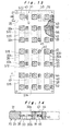
battery modules 9 which are arranged in parallel in batterypower source devices 6 are electrically connected in series by means ofbus bars 28 offirst end plate 19 andbus bars 28 ofsecond end plate 20. The bus bars 28 embedded and fixed infirst end plate 19 are eleven in number, and are indicated in Fig. 10 by S1, S3, SS, S7, S9, S11, S13, S1S, S17, S19, and S21. The 15bus bars 28 that are embedded in fixed insecond end plate 20 are eleven in number are indicated in Fig. 13 by S2, S4, S6, S8, Sb, S12, S14, S16, S18, S20, and S22. The connection relationship of these withbattery modules 9 is shown in Fig. 15. - Strictly speaking, the bus bars indicated by 31 and 32 should be called a minus terminal bar in the case of the former or a plus terminal bar in the case of the latter, rather than bus bars. Although this is not included in the concept of a bus bar according to the present invention, for convenience in description of this embodiment, they are called bus bars and will be described below. The bus bars indicated by S2 S21 have a contact with the plus electrode and a contact with the minus electrode of the
battery modules 9 that are electrically adjacent in series; thus theseadjacent battery modules 9 are electrically connected in series. For example as shown in Fig. 15, the bus bar indicated by S2 is provided with aplus electrode contact 2a and a minus electrode contact 2b, while the bus bar indicated by S21 is equipped with aplus electrode contact 21a andminus electrode contact 21b. The contact indicated by 1ab in Fig. 15 is the minus terminal for the entire batterypower source assembly 8. To this is connected connecting end ring 35a (see Fig. 7) ofmotive power cable 35 connected to the battery driven motor. Also, the contact indicated by 22ab in Fig. 15 is the plus terminal of one of the batterypower source devices 6. To this is connected the connecting end of a connection cable 36 (see Fig. 3) connected to the minus terminal of the other batterypower source device 6. The voltage between the two contacts 1ab and 22ab is about 125V. Connecting cable 36 has flexibility so that electrical connection between the two batterypower source devices second end plate 20 due to thermal expansion/contraction ofbattery modules 9. - As shown in Fig. 7, Fig. 10, Fig. 12 and Fig. 15, in
first end plate 19, leads 37 for measurement of the voltage between the terminals of the units of the twobattery modules bus bars 28 indicated by S1 S3, S5, S7, S9, S11, S13, S15, S17, S19, and S21 such that the voltage V1-3 between bus bars S1 and S3 for example or the voltage V19-21 between bus bars S19 and S21 can be measured. Voltage V1-3 indicates the voltage between the twobattery modules single cells 7 while the voltages V3-5, V5-7, ..., V19-21 shown in Fig. 15 likewise indicate the voltage between the twobattery modules single cells 7 belonging to the corresponding twobattery modules - Leads 37 are arranged as shown in Fig. 10 within the resin plate of
first end plate 19 and are collected into a single location on one side offirst end plate 19, where they are brought together and extracted to the outside, As shown in Fig. 7, leads 37 are fixed to aresin sheet 38 in the form of a tape and lead to a voltage measurement unit. As shown in Fig. 10 and Fig. 11, excess current in leads 37 is prevented by mountingfuses 39 at the junction ofleads 37 and bus bars 28. These fuses 39 are mounted by after-fixing to extensions (fuse mounting elements) 40 for lead connection provided unitarily with bus bars 28. A construction is adopted whereby the front and rear faces of the middle ofextension 40 are exposed to the outside byapertures extension 40 in after-processing,fuse 39 is mounted so as to electrically connect both sides of the disconnected portion (the disconnected portion is shown by an imaginary line in Fig. 11B).Resin moulding 39a is then applied toapertures - The wiring of
leads 37 is only provided infirst end plate 19, while no wiring at all is provided insecond end plate 20. - As shown in Fig. 7, Fig. 10 and Fig. 12, a holding
element 43 for connectingterminal element 16 of connectingwire 15 whereby six of theaforesaid PTC sensors 14 are connected in series is fixed to the resin plate by insertion moulding infirst end plate 19. - Holding
element 43 is provided with ascrew hole 45 5 exposed at a through-hole aperture 44 provided infirst end plate 19. Then, after insertingterminal element 16 into through-hole aperture 44, it is bent and, next, using ascrew 46, as shown in Fig. 12,terminal element 16 is electrically and mechanically connected to holdingelement 43. - Holding
element 43 is provided at both ends with twoscrew holes terminal elements wires 15. However, a holdingelement 15 indicated by P in Fig. 10 and Fig. 16 has only asingle screw hole 45 and acts solely as the minus terminal. - A holding
element 43 as described above is also fixed insecond end plate 20 in the resin plate by insert forming as shown in Fig. 13. The holdingelement 43 of thissecond end plate 20 is also provided with twoscrew holes single screw hole 45 and serves solely as a plus terminal. - Fig. 16 shows a condition in which
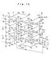
PTC sensors 14 connected to all 126single cells 7 that are provided in batterypower source device 6 are connected electrically in series by means of holdingelements 43 offirst end plate 19 andsecond end plate 20. Since this is the same as the case wherebattery modules 9 shown in Fig. 15 are connected electrically in series usingbus bars 28, a detailed description is omitted. - Respective external lead-out
wires element 43 constituting the minus terminal and indicated by P and to holdingelement 43 constituting the plus terminal and indicated by Q and are connected to aresistance measurement device 49. As a result of the enormous increase in resistance ofPTC sensor 14 connected to asingle cell 7 when there is an abnormal rise in temperature in one of the aforementioned 126single cells 7, this abnormality can be detected byresistance measurement device 49. Consequently, by means of a straightforward construction in which the number of external lead-outwires single cells 7 ofbattery power source 6. A like arrangement is provided in the other batterypower source device 6 constituting batterypower source assembly 8. - As shown in Fig. 3, Fig. 7, Fig. 8 and Fig. 9, both ends of 21
battery modules 9 are fixed and supported in thefirst end plate 19 andsecond end plate 20 in theholder casing 10 of batterypower source device 6. Also,battery modules 9 are supported ininsertion holes 25a of thepartitions anti-vibration rubber sheet 22 in such a way that they project from its front surface.Anti-vibration rubber sheet 22, which is provided with 21 anti-vibration rings 51 is mounted along one face ofpartition 25 by pressing in all the anti-vibration rings 51 intoinsertion holes 25a ofpartition 25. - As already described,
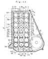
holder casing 10 is partitioned into three spaces by means of twopartitions second end plate 20 to thefirst end plate 19, these are firstpartitioned space 26a, secondpartitioned space 26b, and thirdpartitioned space 26c. In the middle of each partitionedspace adjustment fin plate 21 is inserted from above and fixed tomain casing body 18. Fig. 8 and Fig. 17 show the relationship of cooling adjustment fins 52 (includingfirst stage fin 52a,second stage fin 52b, third stage fin 52c,fourth stage fin 52d,fifth stage fin 52e,sixth stage fin 52f,seventh stage fin 52g, andeighth stage fin 52h) that are formed on coolingadjustment fin plate 21 andbattery modules 9 that are freely inserted ininsertion holes 21a of coolingadjustment fin plate 21. As is well known, means are required in batterypower source device 6 for cooling the batteries in order to prevent abnormal rise in temperature produced by evolution of heat by the batteries. In this embodiment, the lower aperture ofholder casing 10 constitutes anair introduction section 53 while its upper aperture constitutes anair extraction section 54. Cooling of thebattery modules 9, which are arranged horizontally in seven vertical rows and three transverse rows is performed by means of an air current flowing from the bottom (upstream side) to the top (downstream side). - The cooling structure of
battery modules 9 will be described taking as an example second partitionedspace 26b which is located in the middle. As shown in Fig. 7 and Fig. 8, coolingadjustment fins 52 project in both directions from themain plate body 21 of coolingadjustment fin plate 21 and extend to a positionadjacent partitions first stage fin 52a is provided that is arcuate in cross-section about the bottom side of threerespective insertion holes 21a I (the seven insertion holes from the first stage to the seventh stage are respectively indicated by I-VII in Fig. 17) of the lowest stage (also called the first stage), as shown in Fig. 17, as to severely reduce the ratio of the amount of air directly incident on to first-stage battery module 9. - A second-
stage fin 52b, third stage fin 52c, andfourth stage fin 52d of flat H-shape with an interruption section in cross-section are provided in vertically intermediate positions between corresponding insertion holes in, respectively, first stage three insertion holes I and the second stage three insertion holes II thereabove, second stage three insertion holes II and the third stage three insertion holes III thereabove, and third stage three insertion holes III and the fourth stage three insertion holes IV thereabove.Second stage fin 52b is formed with interrupting sections t, t on both sides of the portion of H-shaped cross-section; third stage fin 52c is formed with an interrupting portion t1 in the middle of the portion of H-shaped cross-section; andfourth stage fin 52d is formed with an interrupting portion t2 of greater width in the middle of the portion of H-shaped cross-section. In this way, the ratio of air directly striking secondstage battery module 9 is increased from that in the case of firststage battery module 9; the ratio of air directly striking thirdstage battery module 9 is increased from that of secondstage battery module 9; and the ratio of air directly strikingfourth battery module 9 is increased from that of thirdstage battery module 9. - Between the three insertion holes IV of the fourth 10 stage and the three insertion holes V of the fifth stage on top of these, there are provided
fifth stage fins 52e consisting of four fins arranged next to each other transversely and consisting of two fins of vertically elongate elliptical cross-sectional shape (those shown in Fig. 17 are hollow in cross-section in order to reduce weight, but fins which are not hollow could be employed) and two fins of vertically elongate semi-elliptical cross-section (which could be hollow or not). The two fins of vertically elongate elliptical cross-section that are positioned in the middle are arranged at the centre-points of the four insertion holes IV, IV, V, V in the vertical and horizontal directions of their respective peripheries, while the two fins of vertically elongate semi-elliptical cross-section that are positioned at both ends are located on the outside vertically in the middle of corresponding vertical insertion apertures IV and V, so as to make contact with the side edge of main plate andbody section 21b. Between the three insertion holes V of the fifth stage and the three insertion holes VI of the sixth stage on top of these and between the three insertion holes VI of the sixth stage and the three insertion holes VII of the seventh stage on top of these, there are provided sixstage fins 52f and sevenstage fins 52g consisting of four fins in the same relative positions and of practically the same shape asfins 52e of the fifth stage. Further, in positions above the three insertion holes VII of the uppermost stage (which may also be called the seventh stage), there are providedeighth stage fins 52 is consisting of four fins in the same positional relationship asseventh stage fins 52g, being fins of a shape wherein the upper half of the fins ofseventh stage fins 52g is omitted. The cross-sectional area of the fins ofsixth stage fins 52f is larger than the cross-sectional area of the fins offifth stage fins 52e and the cross-sectional areas of the fins ofseventh stage fins 52g is larger than the cross-sectional area of the fins ofsixth stage fins 52f. By thus making the cross-sectional areas of coolingadjustment fins battery module 9 andcooling adjustment fins 52 is throttled as one goes further in the upwards direction, so that the flow rate of air flowing through the peripheral region ofbattery module 9 of the fifth stage is larger than the flow rate of air flowing through the peripheral region ofbattery module 9 of the fourth stage, the flow rate of air flowing through the peripheral region of sixthstage battery module 9 is increased from the flow rate of air flowing through the peripheral region of thebattery module 9 of the fifth stage, and the flow rate of air flowing through the peripheral region of the seventh stage battery module is greater than the flow rate of air flowing through the peripheral region ofbattery module 9 of the sixth stage. This utilises the fact that, when the flow rate of an air current increases, its cooling effect increases in proportion to the square root. - The air cooling structure of
battery modules 9 was described above taking as example the case of secondpartitioned space 26b; however, the air cooling structure in the other, namely, the firstpartitioned space 26a and thirdpartitioned space 26c is constructed in the same way, In each case, of the large number ofbattery modules 9 arranged in multiple stages in parallel in a direction at right angles to the air current flowing upwards from below, regarding thebattery modules 9 belonging to the lower-stage side groups (in the case shown in Fig. 17,,those arranged in stages 1 to 4) the bottom sides ofbattery modules 9 are covered by screeningfins 52a-52d that adjust the quantity of air that is directly incident onbattery modules 9 and the quantity of air strikingbattery modules 9 is arranged to progressively increase as one goes from the lowest stage (stage 1) to the upper stages (second stage, third stage, fourth stage) . In this way, over-cooling ofbattery modules 9 in the lowest stage is prevented and the amount of air strikingbattery modules 9 is increased going towards the upper stages so as to compensate for the lowering in cooling effect of the air produced by the gradual rise in temperature due to the heat evolved by the batteries. Cooling ofbattery modules 9 of each stage (stage 1 stage 4) can be thus arranged to be performed practically evenly. - As shown in Fig. 17, most of the air that cools the
battery modules 9 belonging to the lower group rises throughpassages right battery modules 9 and thepassages battery modules 9 andside wall 24. Some of it is extracted tobattery modules 9 and is then again merged withpassages stage battery modules 9. Next, the air current is employed to coolbattery modules 9 belonging to the upper-stage group (in the case shown in Fig. 17, those modules which are arranged in the fifth to seventh stages); however, since it has already cooled thebattery modules 9 of the four stages belonging to the lower group, the air temperature is fairly high, so the cooling effect is lowered. In order to compensate for this, for cooling of thebattery modules 9 belonging to the upper-stage group, the air current is throttled, so as to raise the flow speed of the air current aroundbattery modules 9. Abovepassages type fins 52e - 52h in order to raise the flow speed of the air current by narrowing the gaps betweenbattery modules 9, being arranged diagonally belowbattery modules 9 of the fifth, sixth and seventh stages and diagonally abovebattery modules 9 of the seventh stage. Also, these gaps are made progressively narrower going towards the upper stages (fifth stage, sixth stage and seventh stage) to raise the flow rate of the air current aroundbattery modules 9 as to compensate for the loss of cooling effect of the air as it is gradually heated up as it rises: thus practically uniform cooling of thebattery modules 9 in each stage (fifth stage seventh stage) can be achieved. - In this way, a construction is obtained in which all the
battery modules 9 are cooled practically uniformly from the lowest stage to the highest stage. It should be noted that although, in this embodiment, a construction was adopted in which practically uniform cooling of all thebattery modules 9 was achieved by usingscreening fins 52a ~ 52d for the lower fourstage battery modules 9 and flow-path throttling fins 52e ~ 52h for the upper threestage battery modules 9, adjustment of the air flow etc. would of course be possible by for example using screening fins for the lower threestage battery modules 9, providing no fins corresponding to thebattery modules 9 in the fourth, intermediate stage, and employing flow path throttling fins forbattery modules 9 in the upper three stages. - Since the batteries used in this embodiment are nickel-hydrogen secondary cells, it is necessary to devise safety measures in respect of hydrogen leakage in the event of abnormality from the battery cans. The air is fed into battery
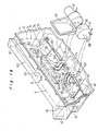
power source device 6 by pressure feed by afan 5 equipped with a sirocco fan. However, it is in particular vital to give consideration to ensuring that hydrogen cannot be fed into the vicinity offan 5 and the interior ofmotor 57 that drives this and/or their vicinity. Accordingly, in this embodiment, as shown in Fig. 8, Fig. 17 and Fig. 18,fan 5 andmotor 57 are arranged to the side and underneathholder casing 10 andfan aperture 58 is arranged belowholder casing 10, so that air that is pressure-fed fromfan 5 passes throughair supply chamber 59 formed belowouter casing 4, and reachesair introduction section 53 at the bottom end ofholder casing 10 10, and then coolsbattery modules 9 by flowing through holder casing 10 from the bottom to the top, then issues fromair extraction section 54 ofholder casing 10, after which it passes throughair discharge chamber 60 formed aboveouter casing 4 and is discharged to the outside ofouter casing 4 from adischarge port 61 formed in the upper side end ofouter casing 4. By the adoption of this construction, even if hydrogen should escape frombattery modules 9 withinholder casing 10, delivery of hydrogen tofan 5 can be prevented. - Fig. 18 shows a construction in which cooling air is pressure-fed to left and right battery
power source devices single fan 5.Fan 5 is equipped with a pair of left and right sirocco fans andfan apertures air extraction port 62 and feeds air uniformly from the pair offan apertures air supply chambers -
Air supply chambers 59 are constituted by a space S enclosed by abottom sheet part 4a ofouter casing 4, the front wall 4b that stands erect in a front position in Fig. 18 ofbottom sheet 4a, and the bottom face ofholder casing 10. At aninlet 63 facingfan aperture 58, there are provided a plurality of curved flow alignment guides 64a, 64b, 64c erected onbottom sheet 4a for guiding air fromfan aperture 58 inwards and sideways.Inlet 63 is arranged in the middle in the width direction ofouter casing 4, being arranged so as to be positioned below firstpartitioned space 26a ofholder casing 10.Bottom sheet 4a is formed so that, withinair supply chamber 59, it has aslope 65 going gradually upwards towards the outside i.e. towards secondpartitioned space 26b and thirdpartitioned space 26c, and has aslope 66 going gradually upwards towards the inside. An air current direction guide 67 of small height that leads the air upwards is provided at a position onslope 65 below the boundary of secondpartitioned space 26b and thirdpartitioned space 26c (see Fig. 8). - The air that is extracted from
inlet 63 is fed through two air passages formed in each space between the three flow alignment guides 64a, 64b and 64c into the inside and into second and thirdpartitioned spaces partitioned space 26a. In order to prevent that this air current goes straight through the air passage and there is insufficiency of the amount of air fed into firstpartitioned space 26a, there is provided an air current direction guide 68 that directs the air upwards in the vicinity of the inlet to the air passage nearestsecond end plate 20. Of the air that issues from the two air passages, some is fed into secondpartitioned space 26b while the remainder is fed to underneath the thirdpartitioned space 26c. Air current direction guide 67 is provided in order to ensure that there is no insufficiency in the amount of air that is fed into secondpartitioned space 26b at this point. The air that is led to below thirdpartitioned space 26c is then led into thirdpartitioned space 26c. - Thus, by providing flow alignment guides 64a, 64b, 64c and air current direction guides 67, 68, and slopes 65, 66, the amount of air that is introduced into partitioned
spaces single cells 7 arranged within the secondpartitioned space 26b are in the centre position ofbattery module 9, it is necessary to apply more cooling to them by means of the air current than in comparison with thesingle cells 7 arranged in first and thirdpartitioned spaces single cells 7 arranged in first and thirdpartitioned spaces - It is therefore desirable to design air current direction guide 67 such as to make the amount of air is directed into second
partitioned space 26b rather larger than the amount of air that is directed into the otherpartitioned spaces - As shown in Fig. 18 and Fig. 8,
outer casing 4 is provided with a holdercasing mounting seat 71 on itsbottom sheet 4a and the left andright holder casings foot portion 72 thereof by means of bolts and nuts 73. Also, aflange 74 is provided mounted on the main automobile body at the periphery ofouter casing 4. - In the above embodiment, as shown in Fig. 15, all the
battery modules 9 in batterypower source device 6 are constantly connected electrically in series. However, for purposes of safety during repair work etc. it is convenient to provide asafety plug 75 in order to cut off temporarily this series connection. For this purpose, as shown by the imaginary line in Fig. 15, a bypass may be provided whereby the locations indicated by 17a and 17b and anopenable safety plug 75 are connected by leads 76, 77 by for example severing S17 bus bars 28 at a location indicted by N in subsequent processing, after exposing these at an aperture provided infirst end plate 19. - With the present invention, the support strength and rigidity of the battery modules can be enormously improved and a battery power source device and end plates for use therein can be provided whereby the battery modules can be assembled in the holder casing in a simple manner and without any possibility of their being wrongly inserted.
- Also with the present invention, the problem of occurrence of twisting between the single cells constituting the battery modules on locking the battery modules to the bus bars can be solved and the benefit can be obtained that voltage detection of the battery modules and/or detection of abnormal rise in temperature of the single cells can be achieved efficiently by means of a straightforward construction. Furthermore, with the present invention, uniform cooling can be performed of the battery modules which are arranged parallel to each other in large numbers in the holder casing, and cooling that is uniform as between the single cells constituting the battery modules can also be achieved.
- In particular, with the present invention, the problem that the cooling effect of the cooling air is lowered because of its increased temperature on the downstream side compared with the upstream side is solved, thereby making it possible to effect uniform cooling of the battery modules whether they are on the upstream side or downstream side. Furthermore, efficient utilisation of the air current can be achieved by preventing over-cooling of the battery modules on the upstream side.
- Furthermore, with the present invention, cooling of a battery power source employing nickel-hydrogen secondary cells can be performed whilst maintaining safety in regard to hydrogen.
- Moreover, cooling of a battery power source assembly comprising a pair of battery power source devices can be performed in a uniform manner for all the battery modules by using only a single pressure-feed fan.
Claims (8)
- A battery power source comprising a cooling device and a large number of battery modules (9), constituted by a plurality of single cells (7) connected in a row electrically and mechanically in series, arranged parallel to each other and held in a holder casing (10) wherein air is forcibly made to flow in one direction within said holder casing (10) thereby cooling the large number of battery modules (9) in said holder casing (10), the direction of flow of the air is in a direction at right angles to the longitudinal direction of said battery modules (9), and wherein means for flow alignment are arranged within said holder casing (10) such that the flow speed of the air flowing through said holder casing (10) is faster on the downstream side than on the upstream side.
- A battery power source according to claim 1, in which, at a location on the downstream said in said holder casing (10), the flow path area is progressively diminished such that the flow speed of air flowing through said holder casing (10) gradually becomes larger in the direction of flow of the air.
- A battery power source comprising a cooling device and a large number of battery modules (9), constituted by a plurality of single cells (7) connected in a row electrically and mechanically in series, arranged parallel to each other and held in a holder casing (10) and air is forcibly made to flow in one direction within said holder casing (10) thereby cooling the large number of battery modules (9) in said holder casing (10), the direction of flow of the air is in a direction at right angles to the longitudinal direction of said battery modules (9), and wherein means for screening are arranged in said holder casing (10) such that the area of said battery modules (9) that is exposed to the air flowing through said holder casing (10) becomes greater from the upstream to the downstream side.
- A battery power source according to claim 3, in which means for screening are arranged only at a location on the upstream side within said holder casing (10) , the means for screening being constituted such that the area of said battery modules (9) that is exposed to air flowing through said holder casing (10) gradually becomes larger going in the direction in which the air is flowing.
- A battery power source comprising a cooling device and a pair of left and right battery power source devices (6) constituted by holding a large number of battery modules (9) consisting of a plurality of single cells (7) connected in a row electrically and mechanically in series arranged horizontally and parallel to each other in a holder casing (10), respective air supply chambers (59) being formed below said holder casings (10) wherein air is fed to a lower aperture of the holder casing (10) of the respective battery power source devices (6) through left and right air supply chambers (59) from a pressure-feed fan (5) so that the battery module (9) is cooled by the air current that is discharged from an upper aperture after rising through said holder casings (10) wherein the pressure-feed fan (5) has two blowing ports (58) that supply air in the direction parallel to the end plates (19, 20) into said respective battery power source devices (6), these blowing ports (58) opening in positions close to a respective one end plate (19, 20) of the battery power source devices (6), the bottom faces of the air supply chambers (59) being formed with a slope (65) whereby the cross-sectional area of the flow path gradually diminishes from the one end plate side towards the other end plate side, and wherein means for flow alignment are arranged within said holder casing (10) whereby the flow rate of the air flowing within said holder casing (10) is faster at the upper than at the lower side.
- A battery power source according to claim 5, wherein the flow path area is gradually diminished at a location in the upper part in said holder casing (10) such that the flow speed of air flowing in said holding casing (10) gradually gets larger in the direction in which the air is flowing.
- A battery power source comprising a cooling device and a pair of left and right battery power source devices (6) constituted by holding a large number of battery modules (9) consisting of a plurality of single cells (7) connected in a row electrically and mechanically in series arranged horizontally and parallel to each other in a holder casing (10), respective air supply chambers (59) being formed below said holder casing (10) wherein air is fed to a lower aperture of the holder casing (10) of the respective battery power source devices (6) through left and right air supply chambers (59) from a pressure-feed fan (5) so that the battery module (9) is cooled by the air current that is discharged from an upper aperture after rising through said holder casings (10) wherein the pressure-feed fan (5) has two blowing ports (58) that supply air in the direction parallel to the end plates (19, 20) into said respective battery power source devices (6), these blowing ports (58) opening in positions close to a respective one end plate (19, 20) of the battery power source devices (6) , the bottom faces of the air supply chambers (59) being formed with a slope (65) whereby the cross-sectional area of the flow path gradually diminishes from the one end plate side towards the other end plate side, and wherein means for screening are arranged in the holder casing (10) whereby the area of the battery modules (9) that is exposed to the air flowing through said holder casing (10) is greater in the upper part than in the lower part.
- A cooling device for a battery power source according to claim 7 wherein means for screening are arranged only in a location of the bottom part in said holder casing (10), the means for screening being constructed such that the area of the battery modules (9) that is exposed to the air flowing through said holder casing (10) gradually gets larger in the direction of flow of the air.
Applications Claiming Priority (5)
| Application Number | Priority Date | Filing Date | Title |
|---|---|---|---|
| JP06995697A JP3774977B2 (en) | 1997-03-24 | 1997-03-24 | Battery power unit and end plate used for it |
| JP6995797 | 1997-03-24 | ||
| JP6995697 | 1997-03-24 | ||
| JP06995797A JP3829396B2 (en) | 1997-03-24 | 1997-03-24 | Battery power cooling system |
| EP19980302116 EP0892450B1 (en) | 1997-03-24 | 1998-03-20 | Battery power source unit |
Related Parent Applications (1)
| Application Number | Title | Priority Date | Filing Date |
|---|---|---|---|
| EP19980302116 Division EP0892450B1 (en) | 1997-03-24 | 1998-03-20 | Battery power source unit |
Publications (2)
| Publication Number | Publication Date |
|---|---|
| EP1376733A2 true EP1376733A2 (en) | 2004-01-02 |
| EP1376733A3 EP1376733A3 (en) | 2004-11-17 |
Family
ID=27239509
Family Applications (1)
| Application Number | Title | Priority Date | Filing Date |
|---|---|---|---|
| EP20030016665 Withdrawn EP1376733A3 (en) | 1997-03-24 | 1998-03-20 | Cooling device for battery power source |
Country Status (1)
| Country | Link |
|---|---|
| EP (1) | EP1376733A3 (en) |
Cited By (5)
| Publication number | Priority date | Publication date | Assignee | Title |
|---|---|---|---|---|
| EP1753070A1 (en) * | 2005-07-29 | 2007-02-14 | Samsung SDI Co., Ltd. | Battery module |
| US7642002B2 (en) | 2004-10-01 | 2010-01-05 | Valeo Systemes Thermiques | Device for cooling batteries of an electronically and/or hybrid powered vehicle |
| EP2913867A1 (en) * | 2014-02-28 | 2015-09-02 | Robert Bosch Gmbh | Battery and vehicle, in particular electric bicycle |
| EP3361556A1 (en) * | 2017-02-08 | 2018-08-15 | Denso Corporation | Power source apparatus and work machine having the same |
| US20220021080A1 (en) * | 2020-07-16 | 2022-01-20 | Rolls-Royce Plc | Battery assembly |
Citations (1)
| Publication number | Priority date | Publication date | Assignee | Title |
|---|---|---|---|---|
| US5585204A (en) | 1993-12-27 | 1996-12-17 | Honda Giken Kogyo Kabushiki Kaisha | Temperature control structure for batteries and battery box for housing such batteries |
Family Cites Families (4)
| Publication number | Priority date | Publication date | Assignee | Title |
|---|---|---|---|---|
| DE2835501A1 (en) * | 1978-08-12 | 1980-02-21 | Deutsche Automobilgesellsch | BATTERY |
| US5015545A (en) * | 1990-01-03 | 1991-05-14 | General Motors Corporation | Method and apparatus for cooling an array of rechargeable batteries |
| US5204609A (en) * | 1991-12-16 | 1993-04-20 | Alisauski Daryl J | Battery cooling apparatus |
| DE4326943A1 (en) * | 1993-08-11 | 1995-02-16 | Varta Batterie | Battery having a plurality of alkaline round cells |
-
1998
- 1998-03-20 EP EP20030016665 patent/EP1376733A3/en not_active Withdrawn
Patent Citations (1)
| Publication number | Priority date | Publication date | Assignee | Title |
|---|---|---|---|---|
| US5585204A (en) | 1993-12-27 | 1996-12-17 | Honda Giken Kogyo Kabushiki Kaisha | Temperature control structure for batteries and battery box for housing such batteries |
Cited By (8)
| Publication number | Priority date | Publication date | Assignee | Title |
|---|---|---|---|---|
| US7642002B2 (en) | 2004-10-01 | 2010-01-05 | Valeo Systemes Thermiques | Device for cooling batteries of an electronically and/or hybrid powered vehicle |
| US7892671B2 (en) | 2004-10-01 | 2011-02-22 | Valeo Climatisation | Device for cooling batteries of an electronically and/or hybrid powered vehicle |
| EP1753070A1 (en) * | 2005-07-29 | 2007-02-14 | Samsung SDI Co., Ltd. | Battery module |
| US8617735B2 (en) | 2005-07-29 | 2013-12-31 | Samsung Sdi Co., Ltd. | Battery module having improved cooling efficiency |
| EP2913867A1 (en) * | 2014-02-28 | 2015-09-02 | Robert Bosch Gmbh | Battery and vehicle, in particular electric bicycle |
| EP3361556A1 (en) * | 2017-02-08 | 2018-08-15 | Denso Corporation | Power source apparatus and work machine having the same |
| US10347956B2 (en) | 2017-02-08 | 2019-07-09 | Denso Corporation | Power source apparatus and work machine having the same |
| US20220021080A1 (en) * | 2020-07-16 | 2022-01-20 | Rolls-Royce Plc | Battery assembly |
Also Published As
| Publication number | Publication date |
|---|---|
| EP1376733A3 (en) | 2004-11-17 |
Similar Documents
| Publication | Publication Date | Title |
|---|---|---|
| EP1030389B1 (en) | Battery housing with integrated cables for voltage measuring | |
| JPH10270095A (en) | Battery power source cooling device | |
| KR102029407B1 (en) | Battery system | |
| KR100530260B1 (en) | Battery power supply | |
| JP3961061B2 (en) | Battery abnormal temperature rise detection device | |
| US6479185B1 (en) | Extended life battery pack with active cooling | |
| EP1976050B1 (en) | Battery module | |
| US10944139B2 (en) | Air cooling battery module having guide vane | |
| KR100872147B1 (en) | Mounting structure of electrical equipment | |
| EP1376733A2 (en) | Cooling device for battery power source | |
| JP5380217B2 (en) | Fuel cell vehicle |
Legal Events
| Date | Code | Title | Description |
|---|---|---|---|
| PUAI | Public reference made under article 153(3) epc to a published international application that has entered the european phase |
Free format text: ORIGINAL CODE: 0009012 |
|
| 17P | Request for examination filed |
Effective date: 20030820 |
|
| AC | Divisional application: reference to earlier application |
Ref document number: 0892450 Country of ref document: EP Kind code of ref document: P |
|
| AK | Designated contracting states |
Kind code of ref document: A2 Designated state(s): DE FR GB |
|
| PUAL | Search report despatched |
Free format text: ORIGINAL CODE: 0009013 |
|
| AK | Designated contracting states |
Kind code of ref document: A3 Designated state(s): DE FR GB |
|
| AKX | Designation fees paid |
Designated state(s): DE FR GB |
|
| RAP1 | Party data changed (applicant data changed or rights of an application transferred) |
Owner name: TOYOTA JIDOSHA KABUSHIKI KAISHA Owner name: PANASONIC CORPORATION |
|
| 17Q | First examination report despatched |
Effective date: 20110714 |
|
| RAP1 | Party data changed (applicant data changed or rights of an application transferred) |
Owner name: PANASONIC CORPORATION Owner name: TOYOTA JIDOSHA KABUSHIKI KAISHA |
|
| RIC1 | Information provided on ipc code assigned before grant |
Ipc: H01M 2/20 19740701ALI20180328BHEP Ipc: H01M 10/6556 20140101ALI20180328BHEP Ipc: H01M 10/652 20140101ALI20180328BHEP Ipc: H01M 10/6566 20140101ALI20180328BHEP Ipc: H01M 10/6557 20140101ALI20180328BHEP Ipc: H01M 10/6563 20140101ALI20180328BHEP Ipc: H01M 10/643 20140101ALN20180328BHEP Ipc: H01M 2/10 19740701AFI20180328BHEP Ipc: H01M 10/625 20140101ALN20180328BHEP Ipc: H01M 10/613 20140101ALI20180328BHEP |
|
| GRAP | Despatch of communication of intention to grant a patent |
Free format text: ORIGINAL CODE: EPIDOSNIGR1 |
|
| STAA | Information on the status of an ep patent application or granted ep patent |
Free format text: STATUS: GRANT OF PATENT IS INTENDED |
|
| RIC1 | Information provided on ipc code assigned before grant |
Ipc: H01M 10/6556 20140101ALI20180426BHEP Ipc: H01M 10/613 20140101ALI20180426BHEP Ipc: H01M 2/20 19740701ALI20180426BHEP Ipc: H01M 2/10 19740701AFI20180426BHEP Ipc: H01M 10/652 20140101ALI20180426BHEP Ipc: H01M 10/6557 20140101ALI20180426BHEP Ipc: H01M 10/643 20140101ALN20180426BHEP Ipc: H01M 10/6566 20140101ALI20180426BHEP Ipc: H01M 10/625 20140101ALN20180426BHEP Ipc: H01M 10/6563 20140101ALI20180426BHEP |
|
| INTG | Intention to grant announced |
Effective date: 20180509 |
|
| RIN1 | Information on inventor provided before grant (corrected) |
Inventor name: KOUZO, KATSUMI Inventor name: KANAMARU, KUNIO Inventor name: MARUKAWA, SHUUHEI Inventor name: WATANABE, KOH Inventor name: INUI, KIWAMU Inventor name: ETOH, TOYOHIKO Inventor name: KOBAYASHI, TAKAKI Inventor name: FUKAO, YASUYOSHI Inventor name: KAKINO, MANABU |
|
| RIC1 | Information provided on ipc code assigned before grant |
Ipc: H01M 10/6563 20140101ALI20180426BHEP Ipc: H01M 10/6556 20140101ALI20180426BHEP Ipc: H01M 10/6566 20140101ALI20180426BHEP Ipc: H01M 10/6557 20140101ALI20180426BHEP Ipc: H01M 10/613 20140101ALI20180426BHEP Ipc: H01M 2/10 20060101AFI20180426BHEP Ipc: H01M 10/652 20140101ALI20180426BHEP Ipc: H01M 2/20 20060101ALI20180426BHEP Ipc: H01M 10/625 20140101ALN20180426BHEP Ipc: H01M 10/643 20140101ALN20180426BHEP |
|
| STAA | Information on the status of an ep patent application or granted ep patent |
Free format text: STATUS: THE APPLICATION IS DEEMED TO BE WITHDRAWN |
|
| 18D | Application deemed to be withdrawn |
Effective date: 20180920 |