EP1376095A1 - Hazardous material detection system - Google Patents
Hazardous material detection system Download PDFInfo
- Publication number
- EP1376095A1 EP1376095A1 EP03014072A EP03014072A EP1376095A1 EP 1376095 A1 EP1376095 A1 EP 1376095A1 EP 03014072 A EP03014072 A EP 03014072A EP 03014072 A EP03014072 A EP 03014072A EP 1376095 A1 EP1376095 A1 EP 1376095A1
- Authority
- EP
- European Patent Office
- Prior art keywords
- gaseous sample
- hazardous material
- ionization
- detection
- gaseous
- Prior art date
- Legal status (The legal status is an assumption and is not a legal conclusion. Google has not performed a legal analysis and makes no representation as to the accuracy of the status listed.)
- Withdrawn
Links
Images


Classifications
-
- H—ELECTRICITY
- H01—ELECTRIC ELEMENTS
- H01J—ELECTRIC DISCHARGE TUBES OR DISCHARGE LAMPS
- H01J49/00—Particle spectrometers or separator tubes
- H01J49/02—Details
- H01J49/04—Arrangements for introducing or extracting samples to be analysed, e.g. vacuum locks; Arrangements for external adjustment of electron- or ion-optical components
-
- G—PHYSICS
- G01—MEASURING; TESTING
- G01N—INVESTIGATING OR ANALYSING MATERIALS BY DETERMINING THEIR CHEMICAL OR PHYSICAL PROPERTIES
- G01N27/00—Investigating or analysing materials by the use of electric, electrochemical, or magnetic means
- G01N27/62—Investigating or analysing materials by the use of electric, electrochemical, or magnetic means by investigating the ionisation of gases, e.g. aerosols; by investigating electric discharges, e.g. emission of cathode
- G01N27/68—Investigating or analysing materials by the use of electric, electrochemical, or magnetic means by investigating the ionisation of gases, e.g. aerosols; by investigating electric discharges, e.g. emission of cathode using electric discharge to ionise a gas
-
- G—PHYSICS
- G01—MEASURING; TESTING
- G01N—INVESTIGATING OR ANALYSING MATERIALS BY DETERMINING THEIR CHEMICAL OR PHYSICAL PROPERTIES
- G01N1/00—Sampling; Preparing specimens for investigation
- G01N1/02—Devices for withdrawing samples
- G01N2001/022—Devices for withdrawing samples sampling for security purposes, e.g. contraband, warfare agents
- G01N2001/024—Devices for withdrawing samples sampling for security purposes, e.g. contraband, warfare agents passengers or luggage
Definitions
- the invention relates to a hazardous material detection system and, more particularly, to a hazardous material detection system well suited for use in detection of nitro compounds etc. that have a nitro group having a low saturated vapor pressure.
- an atmospheric pressure ionization mass spectrometer is employed which is provided with an ion source operable at the atmospheric pressure, to analyze mass of a gaseous sample (gas to be inspected) containing a substance stuck to an incomer to be detected.
- the atmospheric pressure ionization mass spectrometer introduces the gaseous sample to a corona discharge section fitted with a corona discharge needle electrode and an extraction electrode, applies a high voltage between the needle electrode and the extraction electrode to give rise to corona discharge in order to ionize the gaseous sample, introduces the ionized gaseous sample to an analysis section to analyze its mass, and outputs an analysis result to a data processor.
- the data processor is arranged to decide whether the gaseous sample contains the hazardous material based on the analysis result from the atmospheric pressure ionization mass spectrometer and output a result of the decision.
- the gaseous sample introduced to the corona discharge section may contain non-polar to highly polar substances contained in the atmosphere as well as a dust (SiO 2 ) and an organic substance. Furthermore, introduced the gaseous sample contains a variety of miscellaneous substances including those having a low evaporation temperature through a high evaporation temperature.
- an inside of the ion source is contaminated and foreign matter such as silicon (Si) and carbon (C) sticks to the needle electrode and the extraction electrode.
- a liquid chromatograph mass spectrometer is provided with a pore electrode cleaner, to spray a washing solvent such as methanol, acetone, or water every constant time, thereby washing the pore electrode.
- the method employed in the conventional technology of using such a washing solvent as acetone, methanol, or water to wash the needle electrode and the extraction electrode cannot sufficiently remove Si and C stuck to these needle electrode and extraction electrode.
- the conventional technology can be applied to the liquid chromatograph mass spectrometer but not to an atmospheric pressure ionization mass spectrometer, which analyzes mass of the gaseous sample.
- washing solvent as methanol, acetone, or water
- the inside of the ion source section which is heated to 200°C, is cooled down in a moment of time, thereby generating a cold spot. This causes in some cases sticking of dusts and organic substances in the gaseous sample, thereby clogging the pores.
- the conventional technology takes into account only washing the needle electrode and the extraction electrode if the inside of the ion source section is contaminated in connection with corona discharge but not suppressing occurrence of contamination due to ionization.
- the invention provides a hazardous material detection system comprising: gaseous sample introduction means for introducing a gaseous sample containing a substance stuck to a detection object; ionization means for ionizing the gaseous sample introduced by the gaseous sample introduction means, in response to an instruction; mass analysis means for analyzing mass of the gaseous sample ionized by the ionization means; and decision means for deciding whether the gaseous sample contains a hazardous material, based on an analysis result from the mass analysis means, wherein the ionization means ionizes the gaseous sample only for a time specified by the instruction.
- the gaseous sample introduction means such means can be used as to introduce in response to an instruction a gaseous sample containing a substance stuck to a detection object
- the ionization means such means can be used as to ionize the introduced gaseous sample only if the gaseous sample has been introduced by the gaseous sample introduction means and, otherwise, stop ionization of the introduced gaseous sample.
- the gaseous sample introduction means such means can be used as to introduce a gaseous sample containing a substance stuck to a detection object from an inside of a detection object conveyance path which serves to manage entrance and exit of the detection object and also it can be provided with detection object detection means which outputs a detection signal when the detection object is in a detection region of the detection object conveyance path, while as the ionization means, such means can be used as to ionize a gaseous sample introduced by the gaseous sample introduction means in response to the detection signal.
- the ionization means can be arranged to ionize the gaseous sample only for a set time in response to the detection signal.
- alarm generation means can be provided which detects a voltage and a current of at least one of the pair of electrodes of the ionization means and, if at least one of the detected values exceeds a ser value, generates an alarm to notify that a quantity of contamination generated due to ionization has exceeded a set value.
- a gaseous sample is ionized only when necessary, so that occurrence of contamination due to ionization can be suppressed more effectively than in the case of ionizing the gaseous sample all the time, thereby prolonging a service life of a system.
- the gaseous sample can be ionized for a prolonged time, it is possible to improve an accuracy, reproducibility, and a reliability of data obtained by mass analysis. When an alarm is generated also, it is possible to prompt cleaning of the electrodes of the ionization means.
- FIG. 1 is an overall configuration diagram of a hazardous material detection system according to a first embodiment of the invention with which airports and public facilities are equipped.
- a belt conveyor (detection object conveyance path) 12 which serves to monitor entrance and exit of a test sample 10 such as a bag as a detection object, there are arranged an X-ray inspection device 14 and a hazardous material detection device 16 adjacent to the X-ray inspection device 14.
- the X-ray inspection device 14 is provided with an entrance side sensor 18a to detect entrance of the test sample 10 into an X-ray inspection region of the X-ray inspection device 14 and an exit side sensor 18b to detect exit of the test sample 10 from the X-ray inspection region, in such a configuration that these sensors 18a and 18b are connected to the hazardous material detection device 16 via the respective cables. Further, at a center and on an upper side of the X-ray inspection device 14, there is arranged a conical suction section 20, an end of which suction section 20 is connected via gaseous sample introduction piping 22 to the hazardous material detection device 16.
- the suction section 20 is adapted to suck in a vapor of a gaseous sample containing a substance stuck to the test sample 10, for example, a hazardous material containing a nitro compound having a nitro group, which has a very low saturated vapor pressure and so is difficult to detect.
- the gaseous sample thus sucked in is supplied via the gaseous sample introduction piping 22 to the hazardous material detection device 16. That is, the suction section 20 and the gaseous sample introduction piping 22 are arranged as a constituent element of gaseous sample introduction means.
- the hazardous material detection device 16 incorporates an ion source and a corona discharge power supply and also is mounted with a data processor 24 including an indicator and an alarm unit 26.
- the hazardous material detection device 16 comprises an analysis section 28, a corona discharge power supply 30, a differential exhaust section 32, an ion source section 34, a corona discharge section 36, etc., in such a configuration that the cables connected to the sensors 18a and 18b respectively are connected to the corona discharge power supply 30, while the gaseous sample introduction piping 22 is connected to the corona discharge section 36.
- the analysis section 28 is provided with a vacuum vessel 28a whose an inside is constituted of a processing chamber 28b, in which an analyzer 28c connected to the data processor 24 is mounted.
- An inside of the differential exhaust section 32 arranged adjacent to the vacuum vessel 28a is divided into vacuum chambers 32a and 32b which are formed as two stages (front stage and rear stage), which are connected through piping 56 to an exhauster (not shown).
- the vacuum chambers 32a and 32b communicate with each other through a pore 38 and the rear stage side vacuum chamber 32b communicates with the processing chamber 28b through a pore 40.
- the corona discharge section 36 in which a extraction electrode 42 and a needle electrode 44 are arranged as opposite to each other.
- a high voltage is applied between the extraction electrode 42 and the needle electrode 44 by the corona discharge power supply 30.
- a negative DC voltage is applied between the electrodes 42 and 44.
- a positive DC voltage is applied between the electrodes 42 and 44.
- an inside of the corona discharge section 36 communicates with that of the differential exhaust section 32 via a pore 46 formed in the extraction electrode 42 and a pore 48 formed in the differential exhaust section 32. Furthermore, the corona discharge section 36 is connected to flow piping 50, in the middle of which a flow meter 52 and a gaseous sample introduction pump 54 are arranged.
- the gaseous sample introduction pump 54 is adapted to introduce the gaseous sample sent from the gaseous sample introduction piping 22 into the corona discharge section 36 and discharge this introduced gaseous sample through the flow piping 50.
- sucking force of the gaseous sample introduction pump 54 can be adjusted using the flow meter 52. That is, the flow piping 50, the flow meter 52, and the gaseous sample introduction pump 54 constitutes the gaseous sample introduction means together with the suction section 20 and the gaseous sample introduction piping 22.
- the corona discharge section 36 is constituted as ionization means to ionize the gaseous sample by giving rise to corona discharge in a corona discharge region 36a in order to generate ions at the atmospheric pressure or a pressure nearly equal thereto when the gaseous sample is introduced via the gaseous sample introduction piping 22 and a high voltage is applied between the extraction electrode 42 and the needle electrode 44 by the corona discharge power supply 30.
- the ionized gaseous sample is introduced through the pores 46, 48, 38 and 40 to the analyzer 28c, where its mass is analyzed.
- the analyzer 28c is constituted of an ion pool-type ion trap mass spectrometer to detect whether the gaseous sample contains a hazardous material, for example, a nitro compound having a nitro group, which has a very low saturated vapor pressure and is difficult to detect. It is to be noted that the analyzer 28c may come in any other analyzer such as a quadruple mass spectrometer, a magnetic sector-type mass spectrometer, or a gas chromatograph.
- the analyzer 28c is constituted as mass analysis means to detect a molecular weight as mass of the ionized gaseous sample and output this molecular weight as an analysis result to the data processor 24.
- the data processor 24 is constituted as decision means to collate the molecular weight output from the analyzer 28c and a molecular weight of the nitro compound with each other to decide whether they agree, that is, whether the gaseous sample contains the hazardous material and then output a decision result onto a screen.
- the needle electrode 44 and the extraction electrode 42 are provided with an ammeter and a voltmeter (neither of which is shown) to detect a current and a voltage respectively in order to detect conditions of the needle electrode 44 and the extraction electrode 42, that is, whether foreign matter such as Si or C is stuck to the needle electrode 44 or the extraction electrode 42 in connection with ionization, so that detection outputs of the ammeter and the voltmeter are provided to the data processor 24.
- a detection signal is output from the entrance side sensor 18a to turn on the corona discharge power supply 30, which causes the corona discharge section 36 to initiate corona discharge. Simultaneously, vapor generated from the test sample 10 is sucked and introduced as the gaseous sample to the hazardous material detection device 16. If a high voltage is applied between the extraction electrode 42 and the needle electrode 44 by the corona discharge power supply 30 when the gaseous sample is introduced to the corona discharge section 36, corona discharge occurs in the corona discharge region 36a between the extraction electrode 42 and the needle electrode 44, to ionize the gaseous sample.
- the ionized gaseous sample is introduced to the analyzer 28c, where its mass is detected.
- the data processor 24 decides whether a molecular weight obtained as a result of the analysis agrees with the molecular weight of the hazardous material. If the molecular weight obtained as a result of the analysis agrees with the molecular weight of the hazardous material, that is, if a vapor of the hazardous material is detected, the process goes to detailed inspection.
- the result is displayed on a display screen of the data processor 24. Then, if the test sample 10 goes out of the X-ray inspection region, the detection signal is output from the exit side sensor 18b, to turn off the corona discharge power supply 30, thereby terminating inspection of the test sample 10.
- a time required by the test sample 10 to pass through the X-ray inspection region is set to, for example, 15 seconds or so, so that in about 15 seconds after the corona discharge power supply 30 is turned on, the corona discharge power supply 30 is turned off.
- the corona discharge power supply 30 since the detection signal output from the entrance side sensor 18a is used as the instruction in response to which the corona discharge power supply 30 is held ON only for a constant time, to ionize the gaseous sample only for a set time, the corona discharge power supply 30 need not always be held ON, so that it is possible to suppress Si or C from sticking to the needle electrode 44 and the extraction electrode 42 and also to continuously operate the system for a long time, thereby contributing to a prolonged service life of each of the electrodes.
- the corona discharge power supply 30 is turned on or off in accordance with the detection signals from the sensors 18a and 18b, if the test sample 10 is conveyed only in a certain time zone, an operator may operate the data processor 24 such that the corona discharge power supply 30 can be held ON only for a certain time zone.
- an electromagnetic valve 58 which is connected via a controller 60 to a hazardous material detection device 16, so that if a detection signal is output from an entrance side sensor 18a, this detection signal is output to a controller 60, which in turn generates a control signal, in accordance with which the electromagnetic valve 58 is opened only for a constant time but held closed for the other times, with the other components being the same as those of FIG. 1.
- the controller 60 when a test sample 10 is conveyed as a belt conveyor 12 moves and detected by an entrance side sensor 18a, in response to the detection signal of the sensor 18a, the controller 60 outputs the control signal to an electromagnetic valve 58 to open it only for the constant time, so that as a gaseous sample introduction pump 54 operates, a gaseous sample is introduced from gaseous sample introduction piping 22 into an ion source section 34 only for the constant time.
- the gaseous sample thus introduced is ionized at a corona discharge section 36 and analyzed at an analyzer 28, so that an analysis result is displayed on a screen of a data processor 24.
- an exit side sensor 18b When the test sample 10 passes through an X-ray inspection device 14 and goes out of an X-ray inspection region, an exit side sensor 18b outputs the detection signal, so that when this detection signal is input to a controller 60, the control signal output from the controller 60 is turned off to close the electromagnetic valve 58 in order to stop introduction of the gaseous sample to the ion source section 34, while simultaneously a corona discharge power supply 30 is turned off, to terminate inspection on the test sample 10.
- the gaseous sample is introduced into the in source section 34 only for the time of inspecting the test sample 10, it is possible to more effectively suppress foreign matter contained in the gaseous sample from sticking to a needle electrode 44 or a extraction electrode 42, thereby prolonging a service life of each of the electrodes.
- the corona discharge power supply 30 is turned off only for the time of inspection of the test sample 10, so that occurrence of contamination due to ionization can be suppressed more effectively than in the case of ionizing the gaseous sample all the time, thereby prolonging the service life of a system.
- a flow rate of the gaseous sample flowing through the flow piping 50 is controlled by opening and closing the electromagnetic valve 58 and so can be controlled in a moment of time.
- the present embodiment has such a configuration that in the middle of a conduit of gaseous sample introduction piping 22 there is inserted a union T-tube (Y-form joint) 62, while a union T-tube 64 is inserted in such a region of flow piping 50 as to be on a downstream side of an electromagnetic valve 58.
- the T-tubes 62 and 64 are connected to a gaseous sample introduction piping 22 serving as a main path connected to an ion source section 34 and also interconnected with a bypass path 66.
- bypass path 66 In the middle of bypass path 66 there is inserted an electromagnetic valve 68 which is opened all the time to set a flow rate of a gaseous sample flowing through the bypass path 66 larger than that of the gaseous sample flowing through the main path, with the other components being the same as those of FIG. 3.
- the rapid opening/closing operation of the electromagnetic valve 58 may cause corona discharge to become unstable due to a rapid variation in flow rate for a moment. If the corona discharge becomes unstable, it has an influence on analysis of the ionized gaseous sample, thereby giving rise to a detection mistake. Further, since it is required to detect whether a test sample contains a hazardous material in a short period of time, it is not desirable that a decrease in flow rate of the gaseous sample introduced to the ion source section 34 decreases a detection speed.
- the bypass path 66 is provided so that the flow rate of the gaseous sample flowing through the bypass path 66 may be larger than that of the gaseous sample introduced to the ion source section 34. It is, therefore, possible to suppress the influence on the corona discharge without decreasing an entire flow rate, thereby sucking in the large quantity of gaseous sample in a short lapse of time to inspect it in a short lapse of time.
- an operator can control on opening/closing of the electromagnetic valve 58.
- the gaseous sample is introduced into the in source section 34 only for the time of inspection of the test sample 10, it is possible to more effectively suppress foreign matter contained in the gaseous sample from sticking to a needle electrode 44 or a extraction electrode 42, thereby prolonging a service life of each of the electrodes.
- a corona discharge power supply 30 is turned off only for the time of inspection of the test sample 10, so that occurrence of contamination due to ionization can be suppressed more effectively than in the case of ionizing the gaseous sample all the time, thereby prolonging the service life of a system.
- the present embodiment is arranged as a system for detecting an atmospheric gas in a container 70 mounted on a heavy truck, in which a hazardous material detection device 16 detects whether a hazardous material is contained in the atmospheric gas in the container 70 before the container 70 comes in a large-size X-ray inspection device 72 and also which has such a configuration that a gaseous sample introduction piping 22 is mounted at its tip with an analysis probe 74 in place of arranging a sucking section 20, which analysis probe 74 is provided with a changing-over switch in place of sensors 18a and 18b, with the other components being the same as those of FIG. 1.
- a gaseous sample introduction pump 54 operates to introduce the atmospheric gas in the container 70 as the gaseous sample in order to initiate corona discharge on the introduced gaseous sample, so that the ionized gaseous sample is analyzed by an analyzer 28c and a result of this analysis is displayed on a screen of a data processor 24.
- a corona discharge power supply 30 is turned off, to stop the corona discharge at an ion power supply section 34.
- corona discharge is initiated only when the changing-over switch 76 is operated to turn on the corona discharge power supply 30, so that occurrence of contamination due to ionization can be suppressed more effectively than in the case of ionizing the gaseous sample all the time, thereby prolonging the service life of each electrode.
- the changing-over switch 76 is operated to stop introduction of the gaseous sample, so that salt contents or water droplets, even if contained in a large-scale cargo such as the container 70, can be prevented from being introduced always, thereby preventing a needle electrode 44 or a extraction electrode 42 from being contaminated by foreign matter.
- the examiner can also insert the probe 74 into the opening 78 and turn on the changing-over switch 76, to introduce the atmospheric gas in the container 70 and also initiate corona discharge. If no vapor of a hazardous material is detected by this inspection, he can also pull out the probe 74 from the opening 78 and permit passage of the container 70. If the vapor of the hazardous material is detected, the container 70 is inspected in detail.
- the examiner turns on/off the changing-over switch 76
- an operator may operate a data processor 2 to set a time when the atmospheric gas in the container 70 is to be introduced or a time when corona discharge is to be initiated.
- the changing-over switch 76 may be of such a configuration that it is turned on and off automatically when the examiner inserts the probe 74 into the opening 78 and when he pulls out the probe 74 from the opening 78 respectively.
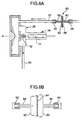
- the present embodiment has such a configuration that a filter unit 80 for collecting dusts and organic substances contained in a gaseous sample is provided partway along a conduit of gaseous sample introduction piping 22, with the other components being the same as those of the preceding embodiments.
- the filter unit 80 comprises a tube body 82, a disk-type filter 84 fixed on the side of an opening of the tube body 82, a tube body 86 coupled as twisted on the side of an outer periphery of the tube body 82, a pipe 88 connected to one end of the tube body 82, and a pipe 90 connected to one end of the tube body 86 in such a configuration that the pipe 88 and 90 are linked to the gaseous sample introduction piping 22 via joints 92 and 94 respectively.
- the filter unit 80 is provided partway along the conduit of the gaseous sample introduction piping 22 to collect the dusts and organic substances contained in the gaseous sample, it is possible to suppress the dusts and organic substances from entering an ion source section 34, thereby more effectively preventing foreign matter from sticking to a extraction electrode 42 or a needle electrode 44.
- the filter unit 80 can be replaced readily by providing it with a mechanism for heating it when the filter unit 80 is provided at a portion partway along the gaseous sample introduction piping 22 and if this portion may possibly become a cold spot or by employing such a construction that only the filter unit 80 can be replaced through in one-touch operation.
- the filter unit 80 such a disk-type filter 84 as to have a large area and a small thickness is used, so that by providing this filter unit 80, it is possible to suppress a detection speed from being decreased.
- the filter unit 80 is linked via the joints 92 and 94 to the gaseous sample introduction piping 22, it can be replaced easily. Further, by mounting a heater in a periphery of the joints 92 and 94 or winding a heat insulating material around them to keep them warm, it is also possible to prevent the gaseous sample from being absorbed to the joints 92 and 94.
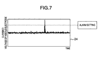
- a voltage and a current of a needle electrode 44 are sequentially measured, a result of the measurement is monitored by a data processor, a result of the monitoring is in turn displayed on a screen of the data processor 24 as shown in FIG. 7. If at least one of the voltage and current of the needle electrode 44 exceeds an alarm set value, an alarm unit 26 can generate an alarm, thereby prompting cleaning.
- the gaseous sample is ionized only when necessary, to make it possible to suppress occurrence of contamination due to ionization more effectively than in the case of ionizing the gaseous sample all the time, thereby prolonging a service life of a system.
Landscapes
- Chemical & Material Sciences (AREA)
- Analytical Chemistry (AREA)
- Life Sciences & Earth Sciences (AREA)
- Electrochemistry (AREA)
- Physics & Mathematics (AREA)
- Health & Medical Sciences (AREA)
- Chemical Kinetics & Catalysis (AREA)
- Biochemistry (AREA)
- General Health & Medical Sciences (AREA)
- General Physics & Mathematics (AREA)
- Immunology (AREA)
- Pathology (AREA)
- Other Investigation Or Analysis Of Materials By Electrical Means (AREA)
- Analysing Materials By The Use Of Radiation (AREA)
- Emergency Alarm Devices (AREA)
Abstract
A hazardous material detection system that can suppress occurrence of contamination due to ionization. When a sensor (18a) detects that a test sample (10) has entered an inspection region of an X-ray inspection device (14) as a belt conveyor (12) moves, a corona discharge power supply in a hazardous material detection device (16) is turned on for a constant time, to introduce a gaseous sample containing a substance stuck to the test sample (10) into the hazardous material detection device (16) via a sucking section (20) and gaseous sample introduction piping (22), in order to ionize the gaseous sample and analyze it at an analyzer (28c), based on a result of which analysis, a data processor (24) decides whether the gaseous sample contains a hazardous material, to display a decision result on a screen. When the test sample (10) is detected by an exit side sensor (18b), the corona discharge power supply is turned off. <IMAGE>
Description
The invention relates to a hazardous material
detection system and, more particularly, to a hazardous
material detection system well suited for use in
detection of nitro compounds etc. that have a nitro
group having a low saturated vapor pressure.
At an airport and other public facilities, it
is attempted to install a hazardous material detection
system that detects a nitro compound having a nitro
group as a hazardous material, to prevent it from being
brought into the airplane or a building. In this kind
of hazardous material detection system, an atmospheric
pressure ionization mass spectrometer is employed which
is provided with an ion source operable at the
atmospheric pressure, to analyze mass of a gaseous
sample (gas to be inspected) containing a substance
stuck to an incomer to be detected.
The atmospheric pressure ionization mass
spectrometer introduces the gaseous sample to a corona
discharge section fitted with a corona discharge needle
electrode and an extraction electrode, applies a high
voltage between the needle electrode and the extraction
electrode to give rise to corona discharge in order to
ionize the gaseous sample, introduces the ionized
gaseous sample to an analysis section to analyze its
mass, and outputs an analysis result to a data
processor. The data processor is arranged to decide
whether the gaseous sample contains the hazardous
material based on the analysis result from the
atmospheric pressure ionization mass spectrometer and
output a result of the decision.
When it is analyzed by the atmospheric
pressure ionization mass spectrometer, the gaseous
sample introduced to the corona discharge section may
contain non-polar to highly polar substances contained
in the atmosphere as well as a dust (SiO2) and an
organic substance. Furthermore, introduced the gaseous
sample contains a variety of miscellaneous substances
including those having a low evaporation temperature
through a high evaporation temperature. When the
variety of substances contained in the gaseous sample
is introduced to the corona discharge section, an
inside of the ion source is contaminated and foreign
matter such as silicon (Si) and carbon (C) sticks to
the needle electrode and the extraction electrode.
When the foreign matter sticks to the needle electrode
and the extraction electrode, corona discharge becomes
unstable, to deteriorate an ionization efficiency of a
sample component as well. Especially if much foreign
matter sticks to them, the gaseous sample cannot pass
through pores in the corona discharge section, thereby
disabling analysis. Therefore, it becomes necessary to
clean the needle electrode and the extraction
electrode, thereby requiring additional time and labor.
To prevent contamination and clogging in the
ion source, such a method has been proposed that, as
described in Jpn. Pat. Appln. KOKAI Publication No. Hei
6-310090 and Jpn. Pat. Appln. KOKAI Publication No. Hei
10-125276, a liquid chromatograph mass spectrometer is
provided with a pore electrode cleaner, to spray a
washing solvent such as methanol, acetone, or water
every constant time, thereby washing the pore
electrode.
The method employed in the conventional
technology of using such a washing solvent as acetone,
methanol, or water to wash the needle electrode and the
extraction electrode cannot sufficiently remove Si and
C stuck to these needle electrode and extraction
electrode. Moreover, the conventional technology can
be applied to the liquid chromatograph mass
spectrometer but not to an atmospheric pressure
ionization mass spectrometer, which analyzes mass of
the gaseous sample. Further, when such washing solvent
as methanol, acetone, or water is used to wash the
electrodes, the inside of the ion source section, which
is heated to 200°C, is cooled down in a moment of time,
thereby generating a cold spot. This causes in some
cases sticking of dusts and organic substances in the
gaseous sample, thereby clogging the pores.
That is, the conventional technology takes
into account only washing the needle electrode and the
extraction electrode if the inside of the ion source
section is contaminated in connection with corona
discharge but not suppressing occurrence of
contamination due to ionization.
It is an object of the invention to provide a
hazardous material detection system that can suppress
occurrence of contamination due to ionization.
To solve these problems, the invention
provides a hazardous material detection system
comprising: gaseous sample introduction means for
introducing a gaseous sample containing a substance
stuck to a detection object; ionization means for
ionizing the gaseous sample introduced by the gaseous
sample introduction means, in response to an
instruction; mass analysis means for analyzing mass of
the gaseous sample ionized by the ionization means; and
decision means for deciding whether the gaseous sample
contains a hazardous material, based on an analysis
result from the mass analysis means, wherein the
ionization means ionizes the gaseous sample only for a
time specified by the instruction.
In arrangement of the hazardous material
detection system, as the gaseous sample introduction
means, such means can be used as to introduce in
response to an instruction a gaseous sample containing
a substance stuck to a detection object, while as the
ionization means, such means can be used as to ionize
the introduced gaseous sample only if the gaseous
sample has been introduced by the gaseous sample
introduction means and, otherwise, stop ionization of
the introduced gaseous sample.
Further, as the gaseous sample introduction
means, such means can be used as to introduce a gaseous
sample containing a substance stuck to a detection
object from an inside of a detection object conveyance
path which serves to manage entrance and exit of the
detection object and also it can be provided with
detection object detection means which outputs a
detection signal when the detection object is in a
detection region of the detection object conveyance
path, while as the ionization means, such means can be
used as to ionize a gaseous sample introduced by the
gaseous sample introduction means in response to the
detection signal. In this case, the ionization means
can be arranged to ionize the gaseous sample only for a
set time in response to the detection signal.
In arrangement of the hazardous material
detection systems, various components can be added as
follow.
Further, in arrangement of the hazardous
material detection systems, alarm generation means can
be provided which detects a voltage and a current of at
least one of the pair of electrodes of the ionization
means and, if at least one of the detected values
exceeds a ser value, generates an alarm to notify that
a quantity of contamination generated due to ionization
has exceeded a set value.
By the means, a gaseous sample is ionized
only when necessary, so that occurrence of contamination
due to ionization can be suppressed more
effectively than in the case of ionizing the gaseous
sample all the time, thereby prolonging a service life
of a system.
Further, since the gaseous sample can be
ionized for a prolonged time, it is possible to improve
an accuracy, reproducibility, and a reliability of data
obtained by mass analysis. When an alarm is generated
also, it is possible to prompt cleaning of the
electrodes of the ionization means.
Other objects, features and advantages of the
invention will become apparent from the following
description of the embodiments of the invention taken
in conjunction with the accompanying drawings.
The following will describe one embodiment of
the invention with reference to drawings. FIG. 1 is an
overall configuration diagram of a hazardous material
detection system according to a first embodiment of the
invention with which airports and public facilities are
equipped. In FIG. 1, in the middle of a belt conveyor
(detection object conveyance path) 12 which serves to
monitor entrance and exit of a test sample 10 such as a
bag as a detection object, there are arranged an X-ray
inspection device 14 and a hazardous material detection
device 16 adjacent to the X-ray inspection device 14.
The X-ray inspection device 14 is provided with an
entrance side sensor 18a to detect entrance of the test
sample 10 into an X-ray inspection region of the X-ray
inspection device 14 and an exit side sensor 18b to
detect exit of the test sample 10 from the X-ray
inspection region, in such a configuration that these
sensors 18a and 18b are connected to the hazardous
material detection device 16 via the respective cables.
Further, at a center and on an upper side of the X-ray
inspection device 14, there is arranged a conical
suction section 20, an end of which suction section 20
is connected via gaseous sample introduction piping 22
to the hazardous material detection device 16. The
suction section 20 is adapted to suck in a vapor of a
gaseous sample containing a substance stuck to the test
sample 10, for example, a hazardous material containing
a nitro compound having a nitro group, which has a very
low saturated vapor pressure and so is difficult to
detect. The gaseous sample thus sucked in is supplied
via the gaseous sample introduction piping 22 to the
hazardous material detection device 16. That is, the
suction section 20 and the gaseous sample introduction
piping 22 are arranged as a constituent element of
gaseous sample introduction means.
The hazardous material detection device 16,
on the other hand, incorporates an ion source and a
corona discharge power supply and also is mounted with
a data processor 24 including an indicator and an alarm
unit 26.
Specifically, as shown in FIG. 2, the
hazardous material detection device 16 comprises an
analysis section 28, a corona discharge power supply
30, a differential exhaust section 32, an ion source
section 34, a corona discharge section 36, etc., in
such a configuration that the cables connected to the
sensors 18a and 18b respectively are connected to the
corona discharge power supply 30, while the gaseous
sample introduction piping 22 is connected to the
corona discharge section 36.
The analysis section 28 is provided with a
vacuum vessel 28a whose an inside is constituted of a
processing chamber 28b, in which an analyzer 28c
connected to the data processor 24 is mounted. An
inside of the differential exhaust section 32 arranged
adjacent to the vacuum vessel 28a is divided into
vacuum chambers 32a and 32b which are formed as two
stages (front stage and rear stage), which are
connected through piping 56 to an exhauster (not
shown). In the differential exhaust section 32, the
vacuum chambers 32a and 32b communicate with each other
through a pore 38 and the rear stage side vacuum
chamber 32b communicates with the processing chamber
28b through a pore 40.
On a partition wall of the front stage side
vacuum chamber 32a of the differential exhaust section
32 is there provided the corona discharge section 36 in
which a extraction electrode 42 and a needle electrode
44 are arranged as opposite to each other. A high
voltage is applied between the extraction electrode 42
and the needle electrode 44 by the corona discharge
power supply 30. For example, to ionize the gaseous
sample (nitro group compound) by negative corona
discharge, a negative DC voltage is applied between the
electrodes 42 and 44. On the other hand, to ionize the
gaseous sample (amino group compound) by positive
corona discharge, a positive DC voltage is applied
between the electrodes 42 and 44. Further, an inside
of the corona discharge section 36 communicates with
that of the differential exhaust section 32 via a pore
46 formed in the extraction electrode 42 and a pore 48
formed in the differential exhaust section 32.
Furthermore, the corona discharge section 36 is
connected to flow piping 50, in the middle of which a
flow meter 52 and a gaseous sample introduction pump 54
are arranged. The gaseous sample introduction pump 54
is adapted to introduce the gaseous sample sent from
the gaseous sample introduction piping 22 into the
corona discharge section 36 and discharge this
introduced gaseous sample through the flow piping 50.
In this case, sucking force of the gaseous sample
introduction pump 54 can be adjusted using the flow
meter 52. That is, the flow piping 50, the flow meter
52, and the gaseous sample introduction pump 54
constitutes the gaseous sample introduction means
together with the suction section 20 and the gaseous
sample introduction piping 22.
The corona discharge section 36 is
constituted as ionization means to ionize the gaseous
sample by giving rise to corona discharge in a corona
discharge region 36a in order to generate ions at the
atmospheric pressure or a pressure nearly equal thereto
when the gaseous sample is introduced via the gaseous
sample introduction piping 22 and a high voltage is
applied between the extraction electrode 42 and the
needle electrode 44 by the corona discharge power
supply 30. The ionized gaseous sample is introduced
through the pores 46, 48, 38 and 40 to the analyzer
28c, where its mass is analyzed.
The analyzer 28c is constituted of an ion
pool-type ion trap mass spectrometer to detect whether
the gaseous sample contains a hazardous material, for
example, a nitro compound having a nitro group, which
has a very low saturated vapor pressure and is
difficult to detect. It is to be noted that the
analyzer 28c may come in any other analyzer such as a
quadruple mass spectrometer, a magnetic sector-type
mass spectrometer, or a gas chromatograph.
The analyzer 28c is constituted as mass
analysis means to detect a molecular weight as mass of
the ionized gaseous sample and output this molecular
weight as an analysis result to the data processor 24.
The data processor 24 is constituted as decision means
to collate the molecular weight output from the
analyzer 28c and a molecular weight of the nitro
compound with each other to decide whether they agree,
that is, whether the gaseous sample contains the
hazardous material and then output a decision result
onto a screen.
Further, in the present embodiment, the
needle electrode 44 and the extraction electrode 42 are
provided with an ammeter and a voltmeter (neither of
which is shown) to detect a current and a voltage
respectively in order to detect conditions of the
needle electrode 44 and the extraction electrode 42,
that is, whether foreign matter such as Si or C is
stuck to the needle electrode 44 or the extraction
electrode 42 in connection with ionization, so that
detection outputs of the ammeter and the voltmeter are
provided to the data processor 24.
In this configuration, when the test sample
10 enters the X-ray inspection region of the X-ray
inspection device 14 as the belt conveyor 12 moves, a
detection signal is output from the entrance side
sensor 18a to turn on the corona discharge power supply
30, which causes the corona discharge section 36 to
initiate corona discharge. Simultaneously, vapor
generated from the test sample 10 is sucked and
introduced as the gaseous sample to the hazardous
material detection device 16. If a high voltage is
applied between the extraction electrode 42 and the
needle electrode 44 by the corona discharge power
supply 30 when the gaseous sample is introduced to the
corona discharge section 36, corona discharge occurs in
the corona discharge region 36a between the extraction
electrode 42 and the needle electrode 44, to ionize the
gaseous sample. The ionized gaseous sample is
introduced to the analyzer 28c, where its mass is
detected. When an analysis result from the analyzer
28c is transmitted to the data processor 24, the data
processor 24 decides whether a molecular weight
obtained as a result of the analysis agrees with the
molecular weight of the hazardous material. If the
molecular weight obtained as a result of the analysis
agrees with the molecular weight of the hazardous
material, that is, if a vapor of the hazardous material
is detected, the process goes to detailed inspection.
If the molecular weight obtained as a result
of the analysis does not agree with the molecular
weight of the hazardous material, on the other hand,
the result is displayed on a display screen of the data
processor 24. Then, if the test sample 10 goes out of
the X-ray inspection region, the detection signal is
output from the exit side sensor 18b, to turn off the
corona discharge power supply 30, thereby terminating
inspection of the test sample 10. A time required by
the test sample 10 to pass through the X-ray inspection
region is set to, for example, 15 seconds or so, so
that in about 15 seconds after the corona discharge
power supply 30 is turned on, the corona discharge
power supply 30 is turned off.
In such a manner, in the present embodiment,
since the detection signal output from the entrance
side sensor 18a is used as the instruction in response
to which the corona discharge power supply 30 is held
ON only for a constant time, to ionize the gaseous
sample only for a set time, the corona discharge power
supply 30 need not always be held ON, so that it is
possible to suppress Si or C from sticking to the
needle electrode 44 and the extraction electrode 42 and
also to continuously operate the system for a long
time, thereby contributing to a prolonged service life
of each of the electrodes.
Although the embodiment has been described
with reference to such an example that the corona
discharge power supply 30 is turned on or off in
accordance with the detection signals from the sensors
18a and 18b, if the test sample 10 is conveyed only in
a certain time zone, an operator may operate the data
processor 24 such that the corona discharge power
supply 30 can be held ON only for a certain time zone.
The following will describe a second
embodiment of a hazardous material detection system
related to the invention with reference to FIG. 3.
According to the present embodiment, in the
middle of a conduit of a flow piping 50 is there
provided an electromagnetic valve 58 which is connected
via a controller 60 to a hazardous material detection
device 16, so that if a detection signal is output from
an entrance side sensor 18a, this detection signal is
output to a controller 60, which in turn generates a
control signal, in accordance with which the electromagnetic
valve 58 is opened only for a constant time
but held closed for the other times, with the other
components being the same as those of FIG. 1.
In the present embodiment, when a test sample
10 is conveyed as a belt conveyor 12 moves and detected
by an entrance side sensor 18a, in response to the
detection signal of the sensor 18a, the controller 60
outputs the control signal to an electromagnetic valve
58 to open it only for the constant time, so that as a
gaseous sample introduction pump 54 operates, a gaseous
sample is introduced from gaseous sample introduction
piping 22 into an ion source section 34 only for the
constant time. The gaseous sample thus introduced is
ionized at a corona discharge section 36 and analyzed
at an analyzer 28, so that an analysis result is
displayed on a screen of a data processor 24.
When the test sample 10 passes through an X-ray
inspection device 14 and goes out of an X-ray
inspection region, an exit side sensor 18b outputs the
detection signal, so that when this detection signal is
input to a controller 60, the control signal output
from the controller 60 is turned off to close the
electromagnetic valve 58 in order to stop introduction
of the gaseous sample to the ion source section 34,
while simultaneously a corona discharge power supply 30
is turned off, to terminate inspection on the test
sample 10.
In the present embodiment, since the gaseous
sample is introduced into the in source section 34 only
for the time of inspecting the test sample 10, it is
possible to more effectively suppress foreign matter
contained in the gaseous sample from sticking to a
needle electrode 44 or a extraction electrode 42,
thereby prolonging a service life of each of the
electrodes. In this case also, the corona discharge
power supply 30 is turned off only for the time of
inspection of the test sample 10, so that occurrence of
contamination due to ionization can be suppressed more
effectively than in the case of ionizing the gaseous
sample all the time, thereby prolonging the service
life of a system.
Further, in the present embodiment, a flow
rate of the gaseous sample flowing through the flow
piping 50 is controlled by opening and closing the
electromagnetic valve 58 and so can be controlled in a
moment of time.
The following will describe a third
embodiment of a hazardous material detection system
related to the invention with reference to FIG. 4. The
present embodiment has such a configuration that in the
middle of a conduit of gaseous sample introduction
piping 22 there is inserted a union T-tube (Y-form
joint) 62, while a union T-tube 64 is inserted in such
a region of flow piping 50 as to be on a downstream
side of an electromagnetic valve 58. The T- tubes 62
and 64 are connected to a gaseous sample introduction
piping 22 serving as a main path connected to an ion
source section 34 and also interconnected with a bypass
path 66. In the middle of bypass path 66 there is
inserted an electromagnetic valve 68 which is opened
all the time to set a flow rate of a gaseous sample
flowing through the bypass path 66 larger than that of
the gaseous sample flowing through the main path, with
the other components being the same as those of FIG. 3.
When the gaseous sample is introduced to the
ion source section 34 by opening/closing the electromagnetic
valve 58, the rapid opening/closing operation
of the electromagnetic valve 58 may cause corona
discharge to become unstable due to a rapid variation
in flow rate for a moment. If the corona discharge
becomes unstable, it has an influence on analysis of
the ionized gaseous sample, thereby giving rise to a
detection mistake. Further, since it is required to
detect whether a test sample contains a hazardous
material in a short period of time, it is not desirable
that a decrease in flow rate of the gaseous sample
introduced to the ion source section 34 decreases a
detection speed.
Therefore, as in the case of the present
embodiment, the bypass path 66 is provided so that the
flow rate of the gaseous sample flowing through the
bypass path 66 may be larger than that of the gaseous
sample introduced to the ion source section 34. It is,
therefore, possible to suppress the influence on the
corona discharge without decreasing an entire flow
rate, thereby sucking in the large quantity of gaseous
sample in a short lapse of time to inspect it in a
short lapse of time.
According to the present embodiment also, to
turn on/off the electromagnetic valve 58, an operator
can control on opening/closing of the electromagnetic
valve 58.
In the present embodiment, since the gaseous
sample is introduced into the in source section 34 only
for the time of inspection of the test sample 10, it is
possible to more effectively suppress foreign matter
contained in the gaseous sample from sticking to a
needle electrode 44 or a extraction electrode 42,
thereby prolonging a service life of each of the
electrodes. Further, a corona discharge power supply
30 is turned off only for the time of inspection of the
test sample 10, so that occurrence of contamination due
to ionization can be suppressed more effectively than
in the case of ionizing the gaseous sample all the
time, thereby prolonging the service life of a system.
Furthermore, it is possible to suck in the
large quantity of gaseous sample in a short lapse of
time to inspect it in a short lapse of time without
having an adverse effect on the corona discharge.
The following will describe a fourth
embodiment of a hazardous material detection system
related to the invention with reference to FIGS. 5A and
5B.
The present embodiment is arranged as a
system for detecting an atmospheric gas in a container
70 mounted on a heavy truck, in which a hazardous
material detection device 16 detects whether a
hazardous material is contained in the atmospheric gas
in the container 70 before the container 70 comes in a
large-size X-ray inspection device 72 and also which
has such a configuration that a gaseous sample
introduction piping 22 is mounted at its tip with an
analysis probe 74 in place of arranging a sucking
section 20, which analysis probe 74 is provided with a
changing-over switch in place of sensors 18a and 18b,
with the other components being the same as those of
FIG. 1.
In the present embodiment, in an airport or
other public facilities, in inspection of the container
70 etc. loaded on a heavy truck, when an examiner
inserts the tip side of the probe 74 into an opening 78
formed in the container 70 and also turns on the
changing-over switch 76, a gaseous sample introduction
pump 54 operates to introduce the atmospheric gas in
the container 70 as the gaseous sample in order to
initiate corona discharge on the introduced gaseous
sample, so that the ionized gaseous sample is analyzed
by an analyzer 28c and a result of this analysis is
displayed on a screen of a data processor 24.
When the examiner turns off the changing-over
switch 76, a corona discharge power supply 30 is turned
off, to stop the corona discharge at an ion power
supply section 34.
In the present embodiment, corona discharge
is initiated only when the changing-over switch 76 is
operated to turn on the corona discharge power supply
30, so that occurrence of contamination due to
ionization can be suppressed more effectively than in
the case of ionizing the gaseous sample all the time,
thereby prolonging the service life of each electrode.
Further, in the present embodiment, when the
container 70 is not to be inspected, the changing-over
switch 76 is operated to stop introduction of the
gaseous sample, so that salt contents or water
droplets, even if contained in a large-scale cargo such
as the container 70, can be prevented from being
introduced always, thereby preventing a needle
electrode 44 or a extraction electrode 42 from being
contaminated by foreign matter.
In the present embodiment, as in the case of
baggage inspection, if any suspicious material
undeclared is found in the container 70 by the large-size
X-ray inspection device 72, the examiner can also
insert the probe 74 into the opening 78 and turn on the
changing-over switch 76, to introduce the atmospheric
gas in the container 70 and also initiate corona
discharge. If no vapor of a hazardous material is
detected by this inspection, he can also pull out the
probe 74 from the opening 78 and permit passage of the
container 70. If the vapor of the hazardous material
is detected, the container 70 is inspected in detail.
Although the present embodiment has been
described with reference to a case where the examiner
turns on/off the changing-over switch 76, an operator
may operate a data processor 2 to set a time when the
atmospheric gas in the container 70 is to be introduced
or a time when corona discharge is to be initiated.
Further, the changing-over switch 76 may be of such a
configuration that it is turned on and off automatically
when the examiner inserts the probe 74 into the
opening 78 and when he pulls out the probe 74 from the
opening 78 respectively.
The following will describe a fifth
embodiment of a hazardous material detection system
related to the invention with reference to FIGS. 6A and
6B. The present embodiment has such a configuration
that a filter unit 80 for collecting dusts and organic
substances contained in a gaseous sample is provided
partway along a conduit of gaseous sample introduction
piping 22, with the other components being the same as
those of the preceding embodiments.
The filter unit 80 comprises a tube body 82,
a disk-type filter 84 fixed on the side of an opening
of the tube body 82, a tube body 86 coupled as twisted
on the side of an outer periphery of the tube body 82,
a pipe 88 connected to one end of the tube body 82, and
a pipe 90 connected to one end of the tube body 86 in
such a configuration that the pipe 88 and 90 are linked
to the gaseous sample introduction piping 22 via joints
92 and 94 respectively.
In the present embodiment, since the filter
unit 80 is provided partway along the conduit of the
gaseous sample introduction piping 22 to collect the
dusts and organic substances contained in the gaseous
sample, it is possible to suppress the dusts and
organic substances from entering an ion source section
34, thereby more effectively preventing foreign matter
from sticking to a extraction electrode 42 or a needle
electrode 44.
Further, the filter unit 80 can be replaced
readily by providing it with a mechanism for heating it
when the filter unit 80 is provided at a portion
partway along the gaseous sample introduction piping 22
and if this portion may possibly become a cold spot or
by employing such a construction that only the filter
unit 80 can be replaced through in one-touch operation.
According to the present embodiment, in the
filter unit 80, such a disk-type filter 84 as to have a
large area and a small thickness is used, so that by
providing this filter unit 80, it is possible to
suppress a detection speed from being decreased.
Further, since the filter unit 80 is linked
via the joints 92 and 94 to the gaseous sample
introduction piping 22, it can be replaced easily.
Further, by mounting a heater in a periphery of the
joints 92 and 94 or winding a heat insulating material
around them to keep them warm, it is also possible to
prevent the gaseous sample from being absorbed to the
joints 92 and 94.
In these embodiments, in a process of
inspecting a test sample 10 or a container 70, a
voltage and a current of a needle electrode 44 are
sequentially measured, a result of the measurement is
monitored by a data processor, a result of the
monitoring is in turn displayed on a screen of the data
processor 24 as shown in FIG. 7. If at least one of
the voltage and current of the needle electrode 44
exceeds an alarm set value, an alarm unit 26 can
generate an alarm, thereby prompting cleaning.
As described above, by the invention, the
gaseous sample is ionized only when necessary, to make
it possible to suppress occurrence of contamination due
to ionization more effectively than in the case of
ionizing the gaseous sample all the time, thereby
prolonging a service life of a system.
It should be further understood by those
skilled in the art that although the foregoing
description has been made on embodiments of the
invention, the invention is not limited thereto and
various changes and modifications may be made without
departing from the spirit of the invention and the
scope of the appended claims.
Claims (5)
- A hazardous material detection system comprising:wherein the ionization means ionizes the gaseous sample only for a time specified by the instruction.gaseous sample introduction means for introducing a gaseous sample containing a substance stuck to a detection object (10);ionization means for ionizing the gaseous sample introduced by the gaseous sample introduction means, in response to an instruction;mass analysis means (28) for analyzing mass of the gaseous sample ionized by the ionization means; anddecision means for deciding whether the gaseous sample contains a hazardous material, based on an analysis result from the mass analysis means (28),
- A hazardous material detection system comprising:gaseous sample introduction means for introducing a gaseous sample containing a substance stuck to a detection object (10), in response to an instruction;ionization means for ionizing the introduced gaseous sample only in the case where the gaseous sample has been introduced by the gaseous sample introduction means and, in the other cases, stopping ionization of the introduced gaseous sample;mass analysis means (28) for analyzing mass of the gaseous sample ionized by the ionization means; anddecision means for deciding whether the gaseous sample contains a hazardous material, based on an analysis result from the mass analysis means (28).
- A hazardous material detection system comprising:wherein the ionization means ionizes the gaseous sample only for a set time in response to the detection signal.gaseous sample introduction means for introducing a gaseous sample containing a substance stuck to a detection object (10) from an inside of a detection object conveyance path (12), which serves to manage entrance and exit of the detection object (10);detection object detection means for outputting a detection signal if the detection object (10) is in a detection region of the detection object conveyance path (12);ionization means for ionizing the gaseous sample introduced by the gaseous sample introduction means, in response to the detection signal;mass analysis means (28) for analyzing mass of the gaseous sample ionized by the ionization means; anddecision means for deciding whether the gaseous sample contains a hazardous material, based on an analysis result from the mass analysis means (28),
- A hazardous material detection system according to any one of claims 1, 2 and 3, wherein:the gaseous sample introduction means is provided with a main path which introduces the gaseous sample from the detection object (10) to the ionization means and a bypass path (66) which discharges the gaseous sample from the detection object (10) as bypassing the ionization means; anda flow rate of the gaseous sample passing through the bypass path (66) is set larger than a flow rate of the gaseous sample passing through the main path.
- The hazardous material detection system according to claim 4, wherein a filter unit (80) which collects dusts and organic substances contained in a fluid flowing through the main path is mounted to the main path on an upstream side of the ionization means.
Applications Claiming Priority (2)
| Application Number | Priority Date | Filing Date | Title |
|---|---|---|---|
| JP2002182847A JP2004028675A (en) | 2002-06-24 | 2002-06-24 | Dangerous goods detection system |
| JP2002182847 | 2002-06-24 |
Publications (1)
| Publication Number | Publication Date |
|---|---|
| EP1376095A1 true EP1376095A1 (en) | 2004-01-02 |
Family
ID=29717557
Family Applications (1)
| Application Number | Title | Priority Date | Filing Date |
|---|---|---|---|
| EP03014072A Withdrawn EP1376095A1 (en) | 2002-06-24 | 2003-06-23 | Hazardous material detection system |
Country Status (4)
| Country | Link |
|---|---|
| US (2) | US6806450B2 (en) |
| EP (1) | EP1376095A1 (en) |
| JP (1) | JP2004028675A (en) |
| CA (1) | CA2433058C (en) |
Cited By (1)
| Publication number | Priority date | Publication date | Assignee | Title |
|---|---|---|---|---|
| CN106500745A (en) * | 2016-10-23 | 2017-03-15 | 郑建灵 | A kind of pipeline inspection detecting instrument |
Families Citing this family (32)
| Publication number | Priority date | Publication date | Assignee | Title |
|---|---|---|---|---|
| JP2004028675A (en) * | 2002-06-24 | 2004-01-29 | Hitachi Ltd | Dangerous goods detection system |
| JP3787116B2 (en) * | 2002-11-06 | 2006-06-21 | 株式会社日立製作所 | How to detect chemical agents |
| JP3800422B2 (en) * | 2003-03-31 | 2006-07-26 | 株式会社日立製作所 | Method and apparatus for detecting a specific drug |
| US8223919B2 (en) | 2003-04-25 | 2012-07-17 | Rapiscan Systems, Inc. | X-ray tomographic inspection systems for the identification of specific target items |
| US8837669B2 (en) | 2003-04-25 | 2014-09-16 | Rapiscan Systems, Inc. | X-ray scanning system |
| US7949101B2 (en) | 2005-12-16 | 2011-05-24 | Rapiscan Systems, Inc. | X-ray scanners and X-ray sources therefor |
| US9113839B2 (en) | 2003-04-25 | 2015-08-25 | Rapiscon Systems, Inc. | X-ray inspection system and method |
| US8243876B2 (en) | 2003-04-25 | 2012-08-14 | Rapiscan Systems, Inc. | X-ray scanners |
| US8451974B2 (en) | 2003-04-25 | 2013-05-28 | Rapiscan Systems, Inc. | X-ray tomographic inspection system for the identification of specific target items |
| GB0525593D0 (en) | 2005-12-16 | 2006-01-25 | Cxr Ltd | X-ray tomography inspection systems |
| US8426821B2 (en) * | 2005-03-01 | 2013-04-23 | Scantech International Pty Ltd. | On-belt analyser system |
| RU2335755C1 (en) * | 2007-01-22 | 2008-10-10 | Федеральное государственное унитарное предприятие "Научно-исследовательский технологический институт имени А.П. Александрова" | Device for residue low-volatile substance detection on fingers |
| WO2008133074A1 (en) | 2007-04-16 | 2008-11-06 | Ulvac, Inc. | Control method of mass spectrometer and spectrometer |
| CN101680856A (en) * | 2007-05-15 | 2010-03-24 | 株式会社爱发科 | Mass spectrometry unit |
| DE102007031502A1 (en) * | 2007-07-06 | 2009-01-08 | Jensen Gmbh | Apparatus and method for loosening laundry items |
| JP2010066243A (en) * | 2008-09-12 | 2010-03-25 | Mitsubishi Heavy Ind Ltd | Apparatus and method for inspecting material |
| JP5648992B2 (en) * | 2009-05-12 | 2015-01-07 | 独立行政法人日本原子力研究開発機構 | High-sensitivity gas analyzer, gas determination method and analyzer system |
| JP5170019B2 (en) * | 2009-07-13 | 2013-03-27 | 株式会社島津製作所 | Gas analyzer |
| US8695443B1 (en) * | 2010-08-30 | 2014-04-15 | Sandia Corporation | Screening system and method of using same |
| IN2015DN02279A (en) * | 2012-09-21 | 2015-08-21 | Smiths Detection Watford Ltd | |
| US8987664B2 (en) * | 2013-02-07 | 2015-03-24 | Shimadzu Corporation | Mass spectrometry device |
| JP6781672B2 (en) * | 2017-06-21 | 2020-11-04 | 株式会社日立製作所 | Deposit inspection method |
| USD859683S1 (en) | 2017-09-21 | 2019-09-10 | Becton, Dickinson And Company | Collection device |
| CN111107939B (en) | 2017-09-21 | 2022-04-12 | 贝克顿·迪金森公司 | System and template to guide the collection of hazardous contaminant samples and methods of using the same |
| CN209400423U (en) | 2017-09-21 | 2019-09-17 | 贝克顿·迪金森公司 | Transverse flow measures object, measurement object reader device and the system including it |
| CN113383222A (en) | 2019-01-28 | 2021-09-10 | 贝克顿·迪金森公司 | Hazardous contaminant collection device with integrated swab and testing device |
| US20200298240A1 (en) * | 2019-03-20 | 2020-09-24 | Becton, Dickinson And Company | Sampling systems and techniques for detection of hazardous contaminants |
| CN113793796B (en) * | 2020-05-29 | 2022-11-11 | 同方威视技术股份有限公司 | Corona discharge type ionization source component and ion mobility spectrometer |
| US11313771B1 (en) | 2020-10-16 | 2022-04-26 | The Government of the United States of America, as renresenten by the Secretary of Homeland Securitv | Sample collection apparatus for scent detection |
| CN114509291A (en) * | 2020-11-16 | 2022-05-17 | 中国石油化工股份有限公司 | Online sampling device of low temperature crystallization result |
| JP7340511B2 (en) * | 2020-12-28 | 2023-09-07 | 株式会社日立製作所 | Inspection method, inspection system and processing equipment |
| JP7768851B2 (en) * | 2022-07-07 | 2025-11-12 | 株式会社日立製作所 | Ion source control method and ion source control device |
Citations (5)
| Publication number | Priority date | Publication date | Assignee | Title |
|---|---|---|---|---|
| US5162652A (en) * | 1991-08-07 | 1992-11-10 | Pcp, Inc. | Method and apparatus for rapid detection of contraband and toxic materials by trace vapor detection using ion mobility spectrometry |
| US5425263A (en) * | 1993-06-01 | 1995-06-20 | Barringer Research Limited | Method for inspecting an article for concealed substances |
| US5465607A (en) * | 1989-06-09 | 1995-11-14 | Research Corporation Technologies, Inc. | Explosive detection screening system |
| EP1093151A2 (en) * | 1999-09-20 | 2001-04-18 | Hitachi, Ltd. | Mass spectrometer, mass spectrometry, and monitoring system |
| US20010042413A1 (en) * | 1998-07-08 | 2001-11-22 | Minoru Sakairi | Explosive detection system and sample collecting device |
Family Cites Families (9)
| Publication number | Priority date | Publication date | Assignee | Title |
|---|---|---|---|---|
| JPS56168621A (en) * | 1980-05-29 | 1981-12-24 | Minolta Camera Co Ltd | Projection system |
| JPS5821713A (en) * | 1981-07-31 | 1983-02-08 | Canon Inc | How to change the magnification of compound eye optical system |
| WO1987001205A1 (en) * | 1985-08-24 | 1987-02-26 | Analytical Security Systems Limited | Method and apparatus for detecting dangerous substances |
| US4849628A (en) * | 1987-05-29 | 1989-07-18 | Martin Marietta Energy Systems, Inc. | Atmospheric sampling glow discharge ionization source |
| JPH06310090A (en) | 1993-04-23 | 1994-11-04 | Hitachi Ltd | Liquid chromatograph mass spectrometer |
| JPH10125276A (en) | 1996-10-24 | 1998-05-15 | Hitachi Ltd | Liquid chromatograph mass spectrometer |
| JP3757820B2 (en) * | 2001-06-13 | 2006-03-22 | 株式会社日立製作所 | Ion source and mass spectrometer using the same |
| JP2003185633A (en) * | 2001-12-19 | 2003-07-03 | Hitachi Ltd | In-container inspection apparatus and method |
| JP2004028675A (en) * | 2002-06-24 | 2004-01-29 | Hitachi Ltd | Dangerous goods detection system |
-
2002
- 2002-06-24 JP JP2002182847A patent/JP2004028675A/en active Pending
-
2003
- 2003-06-20 US US10/465,586 patent/US6806450B2/en not_active Expired - Lifetime
- 2003-06-20 CA CA002433058A patent/CA2433058C/en not_active Expired - Fee Related
- 2003-06-23 EP EP03014072A patent/EP1376095A1/en not_active Withdrawn
-
2004
- 2004-07-09 US US10/886,620 patent/US6940067B2/en not_active Expired - Lifetime
Patent Citations (5)
| Publication number | Priority date | Publication date | Assignee | Title |
|---|---|---|---|---|
| US5465607A (en) * | 1989-06-09 | 1995-11-14 | Research Corporation Technologies, Inc. | Explosive detection screening system |
| US5162652A (en) * | 1991-08-07 | 1992-11-10 | Pcp, Inc. | Method and apparatus for rapid detection of contraband and toxic materials by trace vapor detection using ion mobility spectrometry |
| US5425263A (en) * | 1993-06-01 | 1995-06-20 | Barringer Research Limited | Method for inspecting an article for concealed substances |
| US20010042413A1 (en) * | 1998-07-08 | 2001-11-22 | Minoru Sakairi | Explosive detection system and sample collecting device |
| EP1093151A2 (en) * | 1999-09-20 | 2001-04-18 | Hitachi, Ltd. | Mass spectrometer, mass spectrometry, and monitoring system |
Cited By (1)
| Publication number | Priority date | Publication date | Assignee | Title |
|---|---|---|---|---|
| CN106500745A (en) * | 2016-10-23 | 2017-03-15 | 郑建灵 | A kind of pipeline inspection detecting instrument |
Also Published As
| Publication number | Publication date |
|---|---|
| US6806450B2 (en) | 2004-10-19 |
| JP2004028675A (en) | 2004-01-29 |
| US20040245449A1 (en) | 2004-12-09 |
| US6940067B2 (en) | 2005-09-06 |
| US20030234357A1 (en) | 2003-12-25 |
| CA2433058A1 (en) | 2003-12-24 |
| CA2433058C (en) | 2007-07-24 |
Similar Documents
| Publication | Publication Date | Title |
|---|---|---|
| US6806450B2 (en) | Hazardous material detection system | |
| US9513256B2 (en) | Ion mobility spectrometer which controls carrier gas flow to improve detection | |
| US8022360B2 (en) | Gas pre-concentrator for detection apparatus | |
| US6295860B1 (en) | Explosive detection system and sample collecting device | |
| JP4161608B2 (en) | Dangerous goods detection device | |
| US20140287522A1 (en) | Pulsed Admission of Analyte to Detection Apparatus | |
| US20050092915A1 (en) | Apparatus and method for detecting chemical agents | |
| US8158933B2 (en) | Detector apparatus and pre-concentrator | |
| US20060249023A1 (en) | Filtering particulate materials in continuous emission monitoring systems | |
| JP3787116B2 (en) | How to detect chemical agents | |
| EP1321766A1 (en) | Mass spectrometer for detecting stowaways in containers | |
| EP2038644A1 (en) | Detection apparatus and methods | |
| JP7768851B2 (en) | Ion source control method and ion source control device | |
| JP2003329647A (en) | Explosives detection system | |
| JPH1114614A (en) | Compact analyzer and mass spectrometer coupled to the smaller analyzer | |
| JPH11326281A (en) | Atmospheric change detection method and method and apparatus using the same |
Legal Events
| Date | Code | Title | Description |
|---|---|---|---|
| PUAI | Public reference made under article 153(3) epc to a published international application that has entered the european phase |
Free format text: ORIGINAL CODE: 0009012 |
|
| AK | Designated contracting states |
Kind code of ref document: A1 Designated state(s): AT BE BG CH CY CZ DE DK EE ES FI FR GB GR HU IE IT LI LU MC NL PT RO SE SI SK TR |
|
| AX | Request for extension of the european patent |
Extension state: AL LT LV MK |
|
| 17P | Request for examination filed |
Effective date: 20040614 |
|
| AKX | Designation fees paid |
Designated state(s): DE FR GB |
|
| 17Q | First examination report despatched |
Effective date: 20090326 |
|
| STAA | Information on the status of an ep patent application or granted ep patent |
Free format text: STATUS: THE APPLICATION IS DEEMED TO BE WITHDRAWN |
|
| 18D | Application deemed to be withdrawn |
Effective date: 20090806 |