EP1376091B1 - Pilot tone multiplexing of polarization states in heterodyne optical component analysis - Google Patents
Pilot tone multiplexing of polarization states in heterodyne optical component analysis Download PDFInfo
- Publication number
- EP1376091B1 EP1376091B1 EP03006075A EP03006075A EP1376091B1 EP 1376091 B1 EP1376091 B1 EP 1376091B1 EP 03006075 A EP03006075 A EP 03006075A EP 03006075 A EP03006075 A EP 03006075A EP 1376091 B1 EP1376091 B1 EP 1376091B1
- Authority
- EP
- European Patent Office
- Prior art keywords
- port
- polarization
- optical
- signals
- field
- Prior art date
- Legal status (The legal status is an assumption and is not a legal conclusion. Google has not performed a legal analysis and makes no representation as to the accuracy of the status listed.)
- Expired - Fee Related
Links
Images

Classifications
-
- G—PHYSICS
- G01—MEASURING; TESTING
- G01M—TESTING STATIC OR DYNAMIC BALANCE OF MACHINES OR STRUCTURES; TESTING OF STRUCTURES OR APPARATUS, NOT OTHERWISE PROVIDED FOR
- G01M11/00—Testing of optical apparatus; Testing structures by optical methods not otherwise provided for
- G01M11/30—Testing of optical devices, constituted by fibre optics or optical waveguides
- G01M11/33—Testing of optical devices, constituted by fibre optics or optical waveguides with a light emitter being disposed at one fibre or waveguide end-face, and a light receiver at the other end-face
Definitions
- the present invention relates generally to the optical measurement field. More particularly, the invention relates to a method and apparatus for determining polarization-resolved scattering parameters of an optical device.
- Coherent frequency-swept heterodyne network analysis is a known technique for measuring characteristics of optical devices. For example, characteristics such as group delay, loss and polarization-dependent loss (PDL) can all be obtained using heterodyne network analysis. It is also known that the polarization-resolved scattering parameters provide the most general and complete characterization of an optical device. In particular, once the full polarization-resolved scattering parameters of an optical device have been determined, all other measurable device parameters, such as group delay, PDL and the like can be readily calculated.
- Embodiments in accordance with the invention provide a method and apparatus for determining polarization-resolved scattering parameters of an optical device in which measurements of fields emerging from the optical device can be made accurately and in a reduced period of time.
- a method for determining scattering parameters of an optical device comprises stimulating a port of the optical device with a stimulation field having at least two different polarization states.
- the optical field emerging from the port is then measured in amplitude and phase, and the scattering parameters are calculated using the measurements.
- FIGURES 1 and 2 are block diagrams that schematically illustrate two-port optical device under test (DUT) 10, and the incident and emerging fields at ports 12 and 14 thereof.
- DUT optical device under test
- optical fields a 1 and a 2 are incident on ports 12 and 14, respectively, and optical fields b 1 and b 2 emerge from ports 12 and 14, respectively.
- a polarization-resolved scattering matrix relates the emerging fields to the incident fields, and takes into account the polarization of the fields.
- the fields a 1 , a 2 , b 1 and b 2 are resolved into components in the x-direction and the y-direction to give a complete description of the polarization states of the fields.
- this general polarization-resolved scattering matrix is made up of four 4x4 sub-matrices. Accordingly, the general polarization-resolved scattering matrix can be considered as a set of polarization-resolved sub-matrices. Each of these sub-matrices represents a transmission characteristic or a reflection characteristic of DUT 10.
- FIGURE 3 is a block diagram that schematically illustrates a polarization-resolved S-Matrix test set to assist in explaining the present invention.
- the test set generally designated by reference number 30, includes swept optical source 32 that provides stimulus signals to DUT 34 through polarization synthesizers 36 and 38.
- Polarization synthesizers 36 and 38 control the state of polarization of the stimulus signals applied to input port 40 and output port 42, respectively, of the DUT.
- Emerging optical fields from ports 40 and 42 of DUT 34 are measured using receivers 44 and 46, respectively.
- the receivers are polarization sensitive and each receiver has three outputs.
- Optical switch 45 is operable to determine which of ports 40 or 42 of DUT 34 receives the stimulus signal.
- FIGURE 3 also illustrates reference planes 48 and 50 at input and output ports 40 and 42, respectively, of the DUT. As is known to those skilled in the art, the polarization-resolved scattering matrix is determined at these reference planes.
- S-Parameters Techniques for measuring the scattering parameters (S-Parameters) of optical devices are not completely phase-consistent. This means that the phase reference for some of the scattering parameters is different from the phase reference for other scattering parameters. As a result, not all device characteristics can be calculated directly from the scattering parameters.
- one of the four 4 x 4 sub-matrices is determined at a time.
- the ports of the optical device are stimulated one at a time.
- each port of the optical device is separately stimulated for each polarization state of the incident field, and the magnitude and phase of the emerging field is separately measured for each polarization state.
- Measurement of the emerging field at a port for each polarization state is accomplished using an adjustable polarization synthesizer.
- a polarization synthesizer associated with a first port of a DUT having two ports is set to a first polarization state and the swept optical source is operated to permit the magnitude and phase of the emerging field at the first port to be measured for the first polarization state.
- the polarization synthesizer is then adjusted to a second polarization state and the swept optical source is again operated to permit the magnitude and phase of the emerging field at the first port to be measured for the second polarization state.
- the process in then repeated using a polarization synthesizer associated with the second port of the DUT to measure the optical fields emerging from the second port.
- Each scattering parameter is a complex number (with both an amplitude and a phase).
- the receivers measure the amplitude and phase relative to the amplitude and phase of a local amplifier LO (see FIGURE 3).
- the phase of the optical field is a very strong function of the exact location of the measurement reference plane. For example, a shift in the reference plane of only one optical wavelength will change the phase shift by 360 degrees.
- the output of swept optical source 32 is split into a path to the receiver through the DUT, and a LO path by splitter 54.
- the phase shift is a strong function of the optical frequency. If, for example, the difference in the path lengths is 100 cm, a change in the optical frequency of 3 GHz will change the phase shift by 360 degrees. This effect illustrates that for repeatable and consistent measurements, the optical frequency should be highly repeatable.
- phase shift i. e., a phase uncertainty
- 360 degrees is unacceptable in a high-precision measurement instrument.
- the uncertainty in the frequency needs to be 1 MHz or less.
- polarization-resolved scattering parameters of a polarization-resolved scattering matrix of an optical device it is necessary to measure the magnitude and phase of emerging optical fields at ports of the optical device for incident fields having at least two polarization states.
- a variety of different input polarization states can be used for the measurements.
- a simple and effective combination of two polarization states that is known in the prior art is linearly polarized light in the x and y directions.
- An alternative approach is to use three different polarization states at each port of the DUT. This approach is based on a technique first introduced by R. C. Jones. By using this technique, the ratios of the receiver outputs are calculated at each optical frequency; and from the ratios, all entries in a sub-matrix of a polarization-resolved scattering matrix relative to a reference amplitude and phase can be calculated. Further details of this alternative approach are described in commonly assigned U.S. Patent Application Serial No. US-A-2003231310 filed concurrently herewith and entitled MEASUREMENT OF POLARIZATION-RESOLVED OPTICAL SCATTERING PARAMETERS. The present invention is intended to cover embodiments in which optical stimulation fields having at least two polarization states are applied to a DUT.
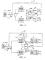
- FIGURE 4 is a block diagram that schematically illustrates polarization-resolved S-Matrix test set 100 for determining scattering parameters of an optical device according to an embodiment of the present invention.
- test set 100 differs from test set 30 of FIGURE 3 in that optical switch 45 of test set 30 has been replaced by splitter 106.
- splitter 106 receives the signal from swept optical source 32 via splitter 54, and directs the split signal to polarization synthesizers 110 and 112.
- the at least two polarization states are applied simultaneously to a port of the DUT; and the contribution of the stimulation field to the x and y components of the emerging field are measured simultaneously.
- providing simultaneous stimulation and measurement using a stimulation field having different polarization states eliminates problems caused by lack of repeatability in setting the optical frequency of the swept optical source between sweeps; and, in addition, significantly speeds up the measurement process.
- two polarization states can be applied simultaneously to a port of optical DUT 34 by replacing adjustable polarization synthesizers 36 and 38 in test set 30 in FIGURE 3 with "dual-mode” polarization synthesizers 110 and 112; and by replacing receivers 44 and 46 in the test set 30 with "dual-mode” receivers 120 and 122.
- dual mode polarization synthesizer 110 and dual-mode receiver 120 are associated with input port 40 of DUT 34
- dual-mode polarization synthesizer 112 and dual-mode receiver 122 are associated with output port 42 of the DUT.
- Each dual-mode polarization synthesizer 110 and 112 simultaneously generates two orthogonal polarization states, in the x and y directions, at its respective port of the DUT as is illustrated in FIGURE 4 with respect to polarization synthesizer 110.
- Each dual-mode receiver detects the emerging optical field at its respective port and resolves the detected field into its two orthogonal (x and y) components.
- each dual-mode receiver resolves that part of the emerging field in the x and y directions that result from the x and y components in the field incident to the DUT.
- the RM 1xx output of the dual-mode receivers is the received field in the x direction, resulting from the x component of the input field.
- RM ijk is the received field in the j direction, resulting from the k component of the input field.
- Dual-mode polarization synthesizers 110 and 112 are identical and dual-mode receivers 120 and 122 are identical. Accordingly, only dual-mode polarization synthesizer 110 and dual-mode receiver 120 are described in detail herein.
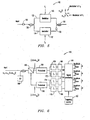
- FIGURE 5 illustrates details of dual-mode polarization synthesizer 110
- FIGURE 6 illustrates details of dual-mode receiver 120.
- dual-mode polarization synthesizer 110 uses pilot-tone multiplexing techniques to identify each of the two orthogonal polarizations in the light input thereto.
- the incoming light to polarization synthesizer 110 from swept optical source 32 is first linearized using polarizer 130; and the linearized light is then split into two paths 132 and 134 by splitter 136.
- the light in paths 132 and 134 is then intensity modulated at frequencies f 1 and f2, respectively, using modulators 140 and 142, respectively. These frequencies are used to identify the signals in dual-mode receiver 120 as will be explained hereinafter.
- the frequencies f 1 and f 2 should generally be at least twice the sampling frequency of the receiver.
- the modulation depth of the pilot tone modulation should be accurately controlled.
- Ninety-degree splice 150 is located at the output of one of the two modulators, e.g., at the output of modulator 142 in FIGURE 5.
- the 90-degree splice ensures that the two modulated fields are orthogonal to one another (one in the x direction and one in the y direction).
- the component of the field in the x direction is modulated at frequency f 1
- the component of the field in the y direction is modulated at frequency f 2 .
- the two orthogonal modulated fields are then combined by combiner 152 to provide a stimulation field having two polarization states for stimulating port 40 of DUT 34.
- Dual-mode receiver 120 is illustrated in greater detail in FIGURE 6. As shown, the emerging field from port 40 of DUT 34 and input into receiver 120 is first combined with LO polarization beam 160. The combined beam is directed to beamsplitter 162 that splits the combined beam into its x and y components. LO polarization beam 160 is at 45 degrees to the beamsplitter axis. The x component signal from beamsplitter 162 is passed through photodiode 164 and the y component signal is passed through photodiode 166 to convert the light signals to electrical signals.
- the x component electrical signal and the y component electrical signal are then passed through pairs of bandpass filters 170, 172 and 174, 176, respectively, to separate the components due to the x and y components of the field incident on port 40.
- Envelope (amplitude) detectors 180, 182, 184 and 186 are placed at each of four inputs to signal processing circuitry 190. The envelope detectors detect the amplitude of the signals at the pilot tone frequencies f 1 and f 2 , and input these amplitude signals to signal processing circuitry 190.
- the phase of each of the field components is detected by frequency counter 192 coupled to signal processing circuitry 190.
- the amplitude and phase of each component of the signal emerging from port 40 of the DUT in each polarization state is thus measured and output from signal processing circuitry 190 as signals RM 1xx , RM 1xy , RM 1yx and RM 1yy . From these signals and from corresponding signals output from dual-mode receiver 122 associated with output port 42 of the DUT, all scattering parameters of DUT 34 can be calculated.
- FIGURE 7 is a flow chart that illustrates steps of method 300 for determining polarization-resolved scattering parameters according to an embodiment of the present invention.
- a port of an optical DUT is first stimulated with a stimulation field having at least two polarization states (step 302).
- the amplitude and phase of each component of the optical field emerging from the port is then measured (step 304), and scattering parameters of the DUT are calculated from the measured emerging field (step 306).
Description
- The present invention relates generally to the optical measurement field. More particularly, the invention relates to a method and apparatus for determining polarization-resolved scattering parameters of an optical device.
- Coherent frequency-swept heterodyne network analysis is a known technique for measuring characteristics of optical devices. For example, characteristics such as group delay, loss and polarization-dependent loss (PDL) can all be obtained using heterodyne network analysis. It is also known that the polarization-resolved scattering parameters provide the most general and complete characterization of an optical device. In particular, once the full polarization-resolved scattering parameters of an optical device have been determined, all other measurable device parameters, such as group delay, PDL and the like can be readily calculated.
- There is a need for a technique for determining polarization-resolved scattering parameters of an optical device in which measurements of fields emerging from the device can be made accurately and in a reduced period of time.
- Embodiments in accordance with the invention provide a method and apparatus for determining polarization-resolved scattering parameters of an optical device in which measurements of fields emerging from the optical device can be made accurately and in a reduced period of time.
- A method for determining scattering parameters of an optical device according to the present invention comprises stimulating a port of the optical device with a stimulation field having at least two different polarization states. The optical field emerging from the port is then measured in amplitude and phase, and the scattering parameters are calculated using the measurements.
- It has been discovered that by stimulating a port of an optical device with a stimulation field having at least two different polarization states, measurements needed to determine scattering parameters of the optical device can be conducted by stimulating the port with only one sweep of a swept optical source. As a result, problems resulting from a lack of repeatability in setting the optical frequency of the swept optical source between sweeps are avoided. Furthermore, because only one sweep of the swept optical source is needed to measure the emerging field at a port for the at least two different polarization states, the overall measurement process can be completed in a reduced period of time.
- Furthermore, the invention provides embodiments with other features and advantages in addition to or in lieu of those discussed above. Many of these features and advantages are apparent from the description below with reference to the following drawings.
-
- FIGURE 1 is a block diagram that schematically illustrates the incident and emerging fields of a device under test (DUT) as represented by a polarization-independent scattering matrix to assist in explaining the present invention;
- FIGURE 2 is a block diagram that schematically illustrates the incident and emerging fields of a DUT as represented by a polarization-resolved scattering matrix to further assist in explaining the present invention;
- FIGURE 3 is a block diagram that schematically illustrates a polarization-resolved S-matrix test set to further assist in explaining the present invention;
- FIGURE 4 is a block diagram that schematically illustrates a polarization-resolved S-Matrix test set according to an embodiment of the present invention;
- FIGURE 5 is a block diagram that schematically illustrates a dual-mode polarization synthesizer of FIGURE 4 in greater detail;
- FIGURE 6 is a block diagram that schematically illustrates a dual-mode receiver of FIGURE 4 in greater detail; and
- FIGURE 7 is a flow chart that illustrates steps of a method for determining scattering parameters of an optical device according to another embodiment of the present invention.
- A scattering matrix (S-Matrix) relates emerging fields to incident fields in an optical device, and can be understood with reference to FIGURES 1 and 2. In particular, FIGURES 1 and 2 are block diagrams that schematically illustrate two-port optical device under test (DUT) 10, and the incident and emerging fields at
ports ports ports 

- A polarization-resolved scattering matrix relates the emerging fields to the incident fields, and takes into account the polarization of the fields. Thus, as shown in FIGURE 2, the fields a 1 , a 2 , b 1 and b 2 are resolved into components in the x-direction and the y-direction to give a complete description of the polarization states of the fields.
- The resolved incident and emerging fields illustrated in FIGURE 2 are related to one another by the following general polarization-resolved scattering matrix:

- It is to be noted that this general polarization-resolved scattering matrix is made up of four 4x4 sub-matrices. Accordingly, the general polarization-resolved scattering matrix can be considered as a set of polarization-resolved sub-matrices. Each of these sub-matrices represents a transmission characteristic or a reflection characteristic of
DUT 10. - In order to determine the polarization-resolved scattering matrix of an optical DUT, it is necessary to place the DUT in a polarization-resolving test set. The test set applies optical stimulus signals to the DUT and measures the outputs from the DUT in amplitude and phase. FIGURE 3 is a block diagram that schematically illustrates a polarization-resolved S-Matrix test set to assist in explaining the present invention.
- As shown in FIGURE 3, the test set, generally designated by
reference number 30, includes sweptoptical source 32 that provides stimulus signals toDUT 34 throughpolarization synthesizers Polarization synthesizers input port 40 andoutput port 42, respectively, of the DUT. Emerging optical fields fromports DUT 34 are measured usingreceivers Optical switch 45 is operable to determine which ofports DUT 34 receives the stimulus signal. - FIGURE 3 also illustrates
reference planes output ports - Techniques for measuring the scattering parameters (S-Parameters) of optical devices are not completely phase-consistent. This means that the phase reference for some of the scattering parameters is different from the phase reference for other scattering parameters. As a result, not all device characteristics can be calculated directly from the scattering parameters.
- In a procedure for determining the polarization-resolved scattering matrix of an optical device, one of the four 4 x 4 sub-matrices is determined at a time. To determine a particular sub-matrix, the ports of the optical device are stimulated one at a time. In addition, to determine all four elements of a sub-matrix, each port of the optical device is separately stimulated for each polarization state of the incident field, and the magnitude and phase of the emerging field is separately measured for each polarization state.
- Measurement of the emerging field at a port for each polarization state is accomplished using an adjustable polarization synthesizer. For example, in a common measurement procedure, a polarization synthesizer associated with a first port of a DUT having two ports is set to a first polarization state and the swept optical source is operated to permit the magnitude and phase of the emerging field at the first port to be measured for the first polarization state. The polarization synthesizer is then adjusted to a second polarization state and the swept optical source is again operated to permit the magnitude and phase of the emerging field at the first port to be measured for the second polarization state. The process in then repeated using a polarization synthesizer associated with the second port of the DUT to measure the optical fields emerging from the second port.
- Each scattering parameter is a complex number (with both an amplitude and a phase). The receivers measure the amplitude and phase relative to the amplitude and phase of a local amplifier LO (see FIGURE 3). At optical frequencies, however, the phase of the optical field is a very strong function of the exact location of the measurement reference plane. For example, a shift in the reference plane of only one optical wavelength will change the phase shift by 360 degrees. Also, as shown in FIGURE 3, the output of swept
optical source 32 is split into a path to the receiver through the DUT, and a LO path bysplitter 54. If there is any difference in the path length between sweptoptical source 32 and a receiver through the DUT compared with the path length through the LO path, the phase shift is a strong function of the optical frequency. If, for example, the difference in the path lengths is 100 cm, a change in the optical frequency of 3 GHz will change the phase shift by 360 degrees. This effect illustrates that for repeatable and consistent measurements, the optical frequency should be highly repeatable. - In practical measurement systems, path lengths of 100 cm or more are common. At the same time, a phase shift (i. e., a phase uncertainty) of 360 degrees is unacceptable in a high-precision measurement instrument. Typically, one would seek an uncertainty of 0.1 degree or better. For a 0.1 degree uncertainty in phase measurements, the uncertainty in the frequency needs to be 1 MHz or less.
- The uncertainty associated with setting the optical frequency of a swept optical source creates difficulties with regard to accurately determining the 4 S-Parameters of a sub-matrix. These difficulties are due to the fact that the 4 S-Parameters are defined in terms of the same phase reference. If a swept optical source is swept through a measurement range once for each input polarization state, the repeatability of the swept optical source should be better than about 1 MHz between sweeps. Alternatively, if the optical source is stepped across the measurement range, the repeatability requirements of the source can be relaxed. Stepped-frequency measurements, however, are not practical in homodyne network analyzer systems where it is required that the optical source be swept continuously.
- The inability of a swept optical source to provide the necessary level of repeatability in setting the optical frequency of the source between sweeps to measure the emerging fields at two polarization states, can result in inaccurate measurements to determine the scattering parameters of an optical device. In addition, because two sweeps of the swept optical source are needed to measure the emerging field at the two polarization states of the incident field, the overall time required to complete the measurements is increased significantly.
- As described previously, to determine polarization-resolved scattering parameters of a polarization-resolved scattering matrix of an optical device, it is necessary to measure the magnitude and phase of emerging optical fields at ports of the optical device for incident fields having at least two polarization states. A variety of different input polarization states can be used for the measurements. For example, a simple and effective combination of two polarization states that is known in the prior art is linearly polarized light in the x and y directions. By measuring the x and y components of the outputs of the receivers in the polarization-resolved S-Matrix test set, all four entries in a 4 x 4 sub-matrix of a polarization-resolved scattering matrix of a DUT can, in principle, be determined.
- An alternative approach is to use three different polarization states at each port of the DUT. This approach is based on a technique first introduced by R. C. Jones. By using this technique, the ratios of the receiver outputs are calculated at each optical frequency; and from the ratios, all entries in a sub-matrix of a polarization-resolved scattering matrix relative to a reference amplitude and phase can be calculated. Further details of this alternative approach are described in commonly assigned U.S. Patent Application Serial No. US-A-2003231310 filed concurrently herewith and entitled MEASUREMENT OF POLARIZATION-RESOLVED OPTICAL SCATTERING PARAMETERS. The present invention is intended to cover embodiments in which optical stimulation fields having at least two polarization states are applied to a DUT.
- FIGURE 4 is a block diagram that schematically illustrates polarization-resolved S-Matrix test set 100 for determining scattering parameters of an optical device according to an embodiment of the present invention. Initially, test set 100 differs from test set 30 of FIGURE 3 in that
optical switch 45 of test set 30 has been replaced bysplitter 106. In particular, as shown in FIGURE 4,splitter 106 receives the signal from sweptoptical source 32 viasplitter 54, and directs the split signal topolarization synthesizers - According to an embodiment of the present invention, the at least two polarization states are applied simultaneously to a port of the DUT; and the contribution of the stimulation field to the x and y components of the emerging field are measured simultaneously. As will be described hereinafter, providing simultaneous stimulation and measurement using a stimulation field having different polarization states eliminates problems caused by lack of repeatability in setting the optical frequency of the swept optical source between sweeps; and, in addition, significantly speeds up the measurement process.
- According to an embodiment of the present invention, two polarization states can be applied simultaneously to a port of
optical DUT 34 by replacingadjustable polarization synthesizers polarization synthesizers receivers receivers mode polarization synthesizer 110 and dual-mode receiver 120 are associated withinput port 40 ofDUT 34, and dual-mode polarization synthesizer 112 and dual-mode receiver 122 are associated withoutput port 42 of the DUT. - Each dual-
mode polarization synthesizer polarization synthesizer 110. Each dual-mode receiver detects the emerging optical field at its respective port and resolves the detected field into its two orthogonal (x and y) components. In addition, each dual-mode receiver resolves that part of the emerging field in the x and y directions that result from the x and y components in the field incident to the DUT. For example, in FIGURE 4, the RM1xx output of the dual-mode receivers is the received field in the x direction, resulting from the x component of the input field. In general terms, RMijk is the received field in the j direction, resulting from the k component of the input field. - Dual-
mode polarization synthesizers mode receivers mode polarization synthesizer 110 and dual-mode receiver 120 are described in detail herein. In particular, FIGURE 5 illustrates details of dual-mode polarization synthesizer 110, and FIGURE 6 illustrates details of dual-mode receiver 120. - With reference to FIGURE 5, dual-
mode polarization synthesizer 110 uses pilot-tone multiplexing techniques to identify each of the two orthogonal polarizations in the light input thereto. In particular, the incoming light topolarization synthesizer 110 from swept optical source 32 (see FIGURE 4) is first linearized usingpolarizer 130; and the linearized light is then split into twopaths splitter 136. The light inpaths modulators mode receiver 120 as will be explained hereinafter. In order to avoid sampling problems inreceiver 120 caused by aliasing, the frequencies f1 and f2 should generally be at least twice the sampling frequency of the receiver. Also, the modulation depth of the pilot tone modulation should be accurately controlled. - Ninety-
degree splice 150 is located at the output of one of the two modulators, e.g., at the output ofmodulator 142 in FIGURE 5. The 90-degree splice ensures that the two modulated fields are orthogonal to one another (one in the x direction and one in the y direction). In the embodiment illustrated in FIGURE 5, the component of the field in the x direction is modulated at frequency f1, and the component of the field in the y direction is modulated at frequency f2. The two orthogonal modulated fields are then combined bycombiner 152 to provide a stimulation field having two polarization states for stimulatingport 40 ofDUT 34. - Dual-
mode receiver 120 is illustrated in greater detail in FIGURE 6. As shown, the emerging field fromport 40 ofDUT 34 and input intoreceiver 120 is first combined withLO polarization beam 160. The combined beam is directed tobeamsplitter 162 that splits the combined beam into its x and y components.LO polarization beam 160 is at 45 degrees to the beamsplitter axis. The x component signal frombeamsplitter 162 is passed throughphotodiode 164 and the y component signal is passed throughphotodiode 166 to convert the light signals to electrical signals. The x component electrical signal and the y component electrical signal are then passed through pairs ofbandpass filters port 40. Envelope (amplitude)detectors processing circuitry 190. The envelope detectors detect the amplitude of the signals at the pilot tone frequencies f1 and f2, and input these amplitude signals to signalprocessing circuitry 190. - The phase of each of the field components is detected by
frequency counter 192 coupled to signalprocessing circuitry 190. As illustrated in FIGURE 6, the amplitude and phase of each component of the signal emerging fromport 40 of the DUT in each polarization state is thus measured and output fromsignal processing circuitry 190 as signals RM1xx, RM1xy, RM1yx and RM1yy. From these signals and from corresponding signals output from dual-mode receiver 122 associated withoutput port 42 of the DUT, all scattering parameters ofDUT 34 can be calculated. - FIGURE 7 is a flow chart that illustrates steps of
method 300 for determining polarization-resolved scattering parameters according to an embodiment of the present invention. As shown in FIGURE 7, a port of an optical DUT is first stimulated with a stimulation field having at least two polarization states (step 302). The amplitude and phase of each component of the optical field emerging from the port is then measured (step 304), and scattering parameters of the DUT are calculated from the measured emerging field (step 306). - While what has been described constitutes exemplary embodiments of the present invention, it should be recognized that the invention can be varied in many ways without departing from the scope thereof. For example, as indicated above, although embodiments herein describe the stimulation of a port of an optical device with a stimulation field having two different polarization states, it is not intended to so limit the invention as a stimulation field having more than two polarization states, e. g., three polarization states, may be used. Because the invention can be varied in many ways, it should be understood that the invention should be limited only insofar as is required by the scope of the following claims.
Claims (10)
- A method for determining scattering parameters of an optical device (34), comprising:stimulating a port (40, 42) of an optical device (34) with a stimulation field having at least two different polarization states;measuring an optical field emerging from the port (40, 42) in amplitude and phase; andcalculating scattering parameters using the measurements.
- The method according to Claim 1. wherein said at least two polarization states comprises two orthogonally polarized states.
- The method according to Claim 1 or 2, wherein said measuring step comprises simultaneously measuring the contributions of the stimulation field to the polarization components of the field emerging from the port (40, 42).
- The method according to one of the preceding claims, wherein said optical device (34) comprises two ports (40, 42), and wherein said steps of stimulating a port (40, 42) and measuring an optical field emerging from the port (40, 42) are performed for each port (40, 42), and wherein said calculating step comprises calculating scattering parameters using the measurements of optical fields emerging from each port (40, 42).
- An apparatus for determining scattering parameters of an optical device (34), comprising:an optical source (32);a polarization synthesizer (110, 112) in a path from said optical source (32) to a port (40, 42) of said optical device (34) for stimulating said port (40, 42) with a stimulation field having at least two different polarization states; anda receiver (120, 122) for measuring an optical field emerging from said port (40; 42) in amplitude and phase, said scattering parameters being calculable using said measurements.
- The apparatus according to Claim 5, wherein said polarization synthesizer (110, 112) stimulates said port (40, 42) with a stimulation field having two orthogonal polarization states.
- The apparatus according to Claim 6, wherein said polarization synthesizer (110, 112) includes a splitter (136) for splitting an input signal from said source (32) into first and second signals, first and second modulators (140, 142) for intensity modulating said first and second signals at first and second frequencies, respectively, to provide first and second modulated signals, a 90-degree splice (150) at an output of one of said first and second modulators (142) such that said first and second modulated signals are orthogonal to one another, and
a combiner (152) for combining said first and second modulated signals to provide said stimulation field. - The apparatus according to Claim 6, wherein said receiver (120, 122) includes a LO polarization beam (160) combined with the field emerging from said port (40, 42) to provide a combined signal, a beamsplitter (162) for splitting the combined signal into first and second orthogonal signals, filters (170, 172, 174, 176) for separating the first and second orthogonal signals into component signals due to contributions of the incident field, detectors (180, 182, 184, 186) for detecting the amplitude of said component signals, and a frequency counter (192) for detecting the phase of said component signals; and
signal processing circuitry (190) for measuring each component signal in amplitude and phase. - The apparatus according to Claim 8, wherein said beamsplitter (162) splits the combined signal into first and second orthogonal optical signals, and wherein said receiver (120, 122) further includes first and second photodiodes (164, 166) for converting said first and second orthogonal optical signals into first and second electrical signals, said filters (170, 172, 174, 176) separating said first sand second electrical signals into said component signals.
- The apparatus according to Claim 5, wherein said polarization synthesizer (110, 112) comprises a first polarization synthesizer (110) for stimulating a first port (40) of said optical device (34) with a stimulation field having at least two polarization states, and wherein said apparatus, further includes a second polarization synthesizer (112) for stimulating a second port (42) of said optical device (34) with a stimulation field having said at least two polarization states; and further wherein said receiver (120,122) comprises a first receiver (120) for measuring the field emerging from said first port (40), and wherein said apparatus further includes a second receiver (122) for measuring a field emerging from said second port (42), said scattering parameters being calculated using the measurements from said first and second receivers (120, 122).
Applications Claiming Priority (2)
| Application Number | Priority Date | Filing Date | Title |
|---|---|---|---|
| US174778 | 2002-06-18 | ||
| US10/174,778 US6894780B2 (en) | 2002-06-18 | 2002-06-18 | Pilot tone multiplexing of polarization states in heterodyne optical component analysis |
Publications (3)
| Publication Number | Publication Date |
|---|---|
| EP1376091A2 EP1376091A2 (en) | 2004-01-02 |
| EP1376091A3 EP1376091A3 (en) | 2004-12-29 |
| EP1376091B1 true EP1376091B1 (en) | 2006-08-30 |
Family
ID=29717812
Family Applications (1)
| Application Number | Title | Priority Date | Filing Date |
|---|---|---|---|
| EP03006075A Expired - Fee Related EP1376091B1 (en) | 2002-06-18 | 2003-03-19 | Pilot tone multiplexing of polarization states in heterodyne optical component analysis |
Country Status (4)
| Country | Link |
|---|---|
| US (1) | US6894780B2 (en) |
| EP (1) | EP1376091B1 (en) |
| JP (1) | JP2004020567A (en) |
| DE (1) | DE60307934T2 (en) |
Families Citing this family (9)
| Publication number | Priority date | Publication date | Assignee | Title |
|---|---|---|---|---|
| JP4725778B2 (en) * | 2005-05-31 | 2011-07-13 | 横河電機株式会社 | Optical property measuring device |
| DE102006025122A1 (en) | 2005-05-31 | 2006-12-07 | Yokogawa Electric Corporation, Musashino | Device for measuring an optical characteristic |
| WO2007014280A2 (en) * | 2005-07-25 | 2007-02-01 | University Of Florida Research Foundation, Inc. | System, device, and methods for embedded s-parameter measurement |
| JP5186993B2 (en) * | 2008-04-30 | 2013-04-24 | 富士通株式会社 | Polarization multiplexed optical transceiver |
| JP5405853B2 (en) * | 2009-02-24 | 2014-02-05 | 日立コンシューマエレクトロニクス株式会社 | Projection display device |
| WO2010131323A1 (en) * | 2009-05-11 | 2010-11-18 | 三菱電機株式会社 | Polarization demultiplexing apparatus |
| CN102045127B (en) * | 2009-10-23 | 2014-12-10 | 华为技术有限公司 | Receiving device, sending device, system and method for photolytic polarization multiplexing |
| US9473948B2 (en) | 2012-05-28 | 2016-10-18 | Huawei Technologies Co., Ltd. | Method and apparatus for analyzing pilot pollution |
| JP2017026989A (en) * | 2015-07-28 | 2017-02-02 | 富士通オプティカルコンポーネンツ株式会社 | Optical transmitter, and control method of optical modulator |
Family Cites Families (7)
| Publication number | Priority date | Publication date | Assignee | Title |
|---|---|---|---|---|
| JPH01147334A (en) | 1987-12-03 | 1989-06-09 | Sumitomo Electric Ind Ltd | Double refractive index measuring instrument for polarization maintaining optical fiber |
| US5227623A (en) * | 1992-01-31 | 1993-07-13 | Hewlett-Packard Company | Method and apparatus for measuring polarization mode dispersion in optical devices |
| US5371597A (en) | 1993-11-23 | 1994-12-06 | At&T Corp. | System and method for measuring polarization dependent loss |
| US6380533B1 (en) | 1999-02-19 | 2002-04-30 | Lucent Technologies Inc. | Method for measurement of first-and second-order polarization mode dispersion vectors in optical fibers |
| US6144450A (en) * | 1999-09-13 | 2000-11-07 | Lucent Technologies | Apparatus and method for improving the accuracy of polarization mode dispersion measurements |
| US6362874B1 (en) * | 2000-03-08 | 2002-03-26 | Lucent Technologies Inc. | Polarization mode dispersion measurement using phase-sensitive sideband detection |
| US6239873B1 (en) * | 2000-11-13 | 2001-05-29 | The United States Of America As Represented By The Secretary Of The Army | Apparatus for simultaneous measurement of two polarization states of scattered light |
-
2002
- 2002-06-18 US US10/174,778 patent/US6894780B2/en not_active Expired - Fee Related
-
2003
- 2003-03-19 DE DE60307934T patent/DE60307934T2/en not_active Expired - Fee Related
- 2003-03-19 EP EP03006075A patent/EP1376091B1/en not_active Expired - Fee Related
- 2003-06-11 JP JP2003165854A patent/JP2004020567A/en active Pending
Also Published As
| Publication number | Publication date |
|---|---|
| EP1376091A2 (en) | 2004-01-02 |
| US6894780B2 (en) | 2005-05-17 |
| DE60307934D1 (en) | 2006-10-12 |
| DE60307934T2 (en) | 2007-04-26 |
| EP1376091A3 (en) | 2004-12-29 |
| US20030231311A1 (en) | 2003-12-18 |
| JP2004020567A (en) | 2004-01-22 |
Similar Documents
| Publication | Publication Date | Title |
|---|---|---|
| US7426021B2 (en) | Interferometric optical analyzer and method for measuring the linear response of an optical component | |
| JP3213104B2 (en) | Apparatus and method for determining polarization mode dispersion of optical device | |
| US7009691B2 (en) | System and method for removing the relative phase uncertainty in device characterizations performed with a polarimeter | |
| JP2005221500A (en) | Heterodyne optical network analysis using signal modulation | |
| US6515276B2 (en) | Heterodyne optical spectrum analyzer with provisions for intensity noise subtraction | |
| EP1376091B1 (en) | Pilot tone multiplexing of polarization states in heterodyne optical component analysis | |
| US6856398B2 (en) | Method of and apparatus for making wavelength-resolved polarimetric measurements | |
| CA2122782C (en) | Apparatus for measuring an ambient physical parameter applied to a highly birefringent sensing fiber and method | |
| US6766115B1 (en) | Multiport optical component testing using a single optical receiver | |
| US7061621B2 (en) | Interferometric-based device and method for determining chromatic dispersion of optical components using a polarimeter | |
| US7466425B2 (en) | Elementary matrix based optical signal/network analyzer | |
| US7280770B2 (en) | Polarization diverse optical receiver using a polarization-dependent beam splitter | |
| US7253906B2 (en) | Polarization state frequency multiplexing | |
| US20080100847A1 (en) | Heterodyne Photonic Dispersion and Loss Analyzer | |
| EP1520162B1 (en) | Polarization diversity detection using a polarization multiplexed local oscillator | |
| JP2003302310A (en) | Test structure for simultaneously deciding characteristics of two ports of optical component using optical network analysis of interferometer base | |
| JP3998460B2 (en) | Method for determining characteristics of optical device and inspection device | |
| US6940594B2 (en) | Measurement of polarization-resolved optical scattering parameters | |
| US20060159452A1 (en) | Polarization resolving heterodyne optical receiver | |
| Babin et al. | Chromatic Dispersion Measurement: The EXFO phase-Shift Method | |
| JP2001091408A (en) | Polarization mode dispersion measurement and zero dispersion measurement device | |
| JPH11287737A (en) | Evaluation apparatus for optical component |
Legal Events
| Date | Code | Title | Description |
|---|---|---|---|
| PUAI | Public reference made under article 153(3) epc to a published international application that has entered the european phase |
Free format text: ORIGINAL CODE: 0009012 |
|
| AK | Designated contracting states |
Kind code of ref document: A2 Designated state(s): AT BE BG CH CY CZ DE DK EE ES FI FR GB GR HU IE IT LI LU MC NL PT SE SI SK TR |
|
| AX | Request for extension of the european patent |
Extension state: AL LT LV MK RO |
|
| PUAL | Search report despatched |
Free format text: ORIGINAL CODE: 0009013 |
|
| AK | Designated contracting states |
Kind code of ref document: A3 Designated state(s): AT BE BG CH CY CZ DE DK EE ES FI FR GB GR HU IE IT LI LU MC NL PT SE SI SK TR |
|
| AX | Request for extension of the european patent |
Extension state: AL LT LV MK RO |
|
| 17P | Request for examination filed |
Effective date: 20050622 |
|
| AKX | Designation fees paid |
Designated state(s): DE FR GB |
|
| GRAP | Despatch of communication of intention to grant a patent |
Free format text: ORIGINAL CODE: EPIDOSNIGR1 |
|
| GRAS | Grant fee paid |
Free format text: ORIGINAL CODE: EPIDOSNIGR3 |
|
| GRAA | (expected) grant |
Free format text: ORIGINAL CODE: 0009210 |
|
| AK | Designated contracting states |
Kind code of ref document: B1 Designated state(s): DE FR GB |
|
| REG | Reference to a national code |
Ref country code: GB Ref legal event code: FG4D |
|
| REF | Corresponds to: |
Ref document number: 60307934 Country of ref document: DE Date of ref document: 20061012 Kind code of ref document: P |
|
| RAP2 | Party data changed (patent owner data changed or rights of a patent transferred) |
Owner name: AGILENT TECHNOLOGIES, INC. |
|
| ET | Fr: translation filed | ||
| PGFP | Annual fee paid to national office [announced via postgrant information from national office to epo] |
Ref country code: DE Payment date: 20070430 Year of fee payment: 5 |
|
| PLBE | No opposition filed within time limit |
Free format text: ORIGINAL CODE: 0009261 |
|
| STAA | Information on the status of an ep patent application or granted ep patent |
Free format text: STATUS: NO OPPOSITION FILED WITHIN TIME LIMIT |
|
| 26N | No opposition filed |
Effective date: 20070531 |
|
| PGFP | Annual fee paid to national office [announced via postgrant information from national office to epo] |
Ref country code: GB Payment date: 20070425 Year of fee payment: 5 |
|
| PGFP | Annual fee paid to national office [announced via postgrant information from national office to epo] |
Ref country code: FR Payment date: 20070417 Year of fee payment: 5 |
|
| GBPC | Gb: european patent ceased through non-payment of renewal fee |
Effective date: 20080319 |
|
| REG | Reference to a national code |
Ref country code: FR Ref legal event code: ST Effective date: 20081125 |
|
| PG25 | Lapsed in a contracting state [announced via postgrant information from national office to epo] |
Ref country code: DE Free format text: LAPSE BECAUSE OF NON-PAYMENT OF DUE FEES Effective date: 20081001 |
|
| PG25 | Lapsed in a contracting state [announced via postgrant information from national office to epo] |
Ref country code: FR Free format text: LAPSE BECAUSE OF NON-PAYMENT OF DUE FEES Effective date: 20080331 |
|
| PG25 | Lapsed in a contracting state [announced via postgrant information from national office to epo] |
Ref country code: GB Free format text: LAPSE BECAUSE OF NON-PAYMENT OF DUE FEES Effective date: 20080319 |