EP1376020A1 - Verfahren sowie Vorrichtung zur Temperierung von Aussenluft für die Wohnungsbelüftung - Google Patents
Verfahren sowie Vorrichtung zur Temperierung von Aussenluft für die Wohnungsbelüftung Download PDFInfo
- Publication number
- EP1376020A1 EP1376020A1 EP02013884A EP02013884A EP1376020A1 EP 1376020 A1 EP1376020 A1 EP 1376020A1 EP 02013884 A EP02013884 A EP 02013884A EP 02013884 A EP02013884 A EP 02013884A EP 1376020 A1 EP1376020 A1 EP 1376020A1
- Authority
- EP
- European Patent Office
- Prior art keywords
- fresh air
- carrier medium
- heat exchanger
- air
- outside
- Prior art date
- Legal status (The legal status is an assumption and is not a legal conclusion. Google has not performed a legal analysis and makes no representation as to the accuracy of the status listed.)
- Granted
Links
- 238000000034 method Methods 0.000 title claims abstract description 25
- 238000009423 ventilation Methods 0.000 title claims abstract description 17
- 238000005496 tempering Methods 0.000 title description 2
- 239000003673 groundwater Substances 0.000 claims description 6
- 239000012267 brine Substances 0.000 claims description 5
- HPALAKNZSZLMCH-UHFFFAOYSA-M sodium;chloride;hydrate Chemical compound O.[Na+].[Cl-] HPALAKNZSZLMCH-UHFFFAOYSA-M 0.000 claims description 5
- 239000000523 sample Substances 0.000 claims description 4
- 239000007788 liquid Substances 0.000 claims description 2
- 238000010438 heat treatment Methods 0.000 abstract description 8
- 230000003750 conditioning effect Effects 0.000 abstract 1
- 238000001816 cooling Methods 0.000 description 6
- 238000007710 freezing Methods 0.000 description 6
- 230000008014 freezing Effects 0.000 description 6
- 238000011084 recovery Methods 0.000 description 3
- 238000012546 transfer Methods 0.000 description 3
- XLYOFNOQVPJJNP-UHFFFAOYSA-N water Substances O XLYOFNOQVPJJNP-UHFFFAOYSA-N 0.000 description 3
- 238000010276 construction Methods 0.000 description 2
- 230000005855 radiation Effects 0.000 description 2
- 238000009420 retrofitting Methods 0.000 description 2
- 238000010792 warming Methods 0.000 description 2
- 238000013461 design Methods 0.000 description 1
- 238000005485 electric heating Methods 0.000 description 1
- 238000005265 energy consumption Methods 0.000 description 1
- 238000003780 insertion Methods 0.000 description 1
- 230000037431 insertion Effects 0.000 description 1
- 238000012423 maintenance Methods 0.000 description 1
- 238000009418 renovation Methods 0.000 description 1
- 238000000926 separation method Methods 0.000 description 1
Images

Classifications
-
- F—MECHANICAL ENGINEERING; LIGHTING; HEATING; WEAPONS; BLASTING
- F24—HEATING; RANGES; VENTILATING
- F24F—AIR-CONDITIONING; AIR-HUMIDIFICATION; VENTILATION; USE OF AIR CURRENTS FOR SCREENING
- F24F5/00—Air-conditioning systems or apparatus not covered by F24F1/00 or F24F3/00, e.g. using solar heat or combined with household units such as an oven or water heater
- F24F5/0046—Air-conditioning systems or apparatus not covered by F24F1/00 or F24F3/00, e.g. using solar heat or combined with household units such as an oven or water heater using natural energy, e.g. solar energy, energy from the ground
-
- F—MECHANICAL ENGINEERING; LIGHTING; HEATING; WEAPONS; BLASTING
- F24—HEATING; RANGES; VENTILATING
- F24T—GEOTHERMAL COLLECTORS; GEOTHERMAL SYSTEMS
- F24T10/00—Geothermal collectors
- F24T10/10—Geothermal collectors with circulation of working fluids through underground channels, the working fluids not coming into direct contact with the ground
-
- F—MECHANICAL ENGINEERING; LIGHTING; HEATING; WEAPONS; BLASTING
- F24—HEATING; RANGES; VENTILATING
- F24F—AIR-CONDITIONING; AIR-HUMIDIFICATION; VENTILATION; USE OF AIR CURRENTS FOR SCREENING
- F24F5/00—Air-conditioning systems or apparatus not covered by F24F1/00 or F24F3/00, e.g. using solar heat or combined with household units such as an oven or water heater
- F24F5/0046—Air-conditioning systems or apparatus not covered by F24F1/00 or F24F3/00, e.g. using solar heat or combined with household units such as an oven or water heater using natural energy, e.g. solar energy, energy from the ground
- F24F2005/0057—Air-conditioning systems or apparatus not covered by F24F1/00 or F24F3/00, e.g. using solar heat or combined with household units such as an oven or water heater using natural energy, e.g. solar energy, energy from the ground receiving heat-exchange fluid from a closed circuit in the ground
-
- Y—GENERAL TAGGING OF NEW TECHNOLOGICAL DEVELOPMENTS; GENERAL TAGGING OF CROSS-SECTIONAL TECHNOLOGIES SPANNING OVER SEVERAL SECTIONS OF THE IPC; TECHNICAL SUBJECTS COVERED BY FORMER USPC CROSS-REFERENCE ART COLLECTIONS [XRACs] AND DIGESTS
- Y02—TECHNOLOGIES OR APPLICATIONS FOR MITIGATION OR ADAPTATION AGAINST CLIMATE CHANGE
- Y02A—TECHNOLOGIES FOR ADAPTATION TO CLIMATE CHANGE
- Y02A30/00—Adapting or protecting infrastructure or their operation
- Y02A30/27—Relating to heating, ventilation or air conditioning [HVAC] technologies
- Y02A30/272—Solar heating or cooling
-
- Y—GENERAL TAGGING OF NEW TECHNOLOGICAL DEVELOPMENTS; GENERAL TAGGING OF CROSS-SECTIONAL TECHNOLOGIES SPANNING OVER SEVERAL SECTIONS OF THE IPC; TECHNICAL SUBJECTS COVERED BY FORMER USPC CROSS-REFERENCE ART COLLECTIONS [XRACs] AND DIGESTS
- Y02—TECHNOLOGIES OR APPLICATIONS FOR MITIGATION OR ADAPTATION AGAINST CLIMATE CHANGE
- Y02B—CLIMATE CHANGE MITIGATION TECHNOLOGIES RELATED TO BUILDINGS, e.g. HOUSING, HOUSE APPLIANCES OR RELATED END-USER APPLICATIONS
- Y02B10/00—Integration of renewable energy sources in buildings
- Y02B10/20—Solar thermal
-
- Y—GENERAL TAGGING OF NEW TECHNOLOGICAL DEVELOPMENTS; GENERAL TAGGING OF CROSS-SECTIONAL TECHNOLOGIES SPANNING OVER SEVERAL SECTIONS OF THE IPC; TECHNICAL SUBJECTS COVERED BY FORMER USPC CROSS-REFERENCE ART COLLECTIONS [XRACs] AND DIGESTS
- Y02—TECHNOLOGIES OR APPLICATIONS FOR MITIGATION OR ADAPTATION AGAINST CLIMATE CHANGE
- Y02B—CLIMATE CHANGE MITIGATION TECHNOLOGIES RELATED TO BUILDINGS, e.g. HOUSING, HOUSE APPLIANCES OR RELATED END-USER APPLICATIONS
- Y02B10/00—Integration of renewable energy sources in buildings
- Y02B10/40—Geothermal heat-pumps
-
- Y—GENERAL TAGGING OF NEW TECHNOLOGICAL DEVELOPMENTS; GENERAL TAGGING OF CROSS-SECTIONAL TECHNOLOGIES SPANNING OVER SEVERAL SECTIONS OF THE IPC; TECHNICAL SUBJECTS COVERED BY FORMER USPC CROSS-REFERENCE ART COLLECTIONS [XRACs] AND DIGESTS
- Y02—TECHNOLOGIES OR APPLICATIONS FOR MITIGATION OR ADAPTATION AGAINST CLIMATE CHANGE
- Y02E—REDUCTION OF GREENHOUSE GAS [GHG] EMISSIONS, RELATED TO ENERGY GENERATION, TRANSMISSION OR DISTRIBUTION
- Y02E10/00—Energy generation through renewable energy sources
- Y02E10/10—Geothermal energy
Definitions
- the invention relates to a method and a device for tempering Outside air for home ventilation.
- the preheating of the fresh air takes place in particular under the aspect of Minimizing costs using heat recovery equipment.
- the one supplied from the outside Fresh air in heat exchangers led past the used exhaust air, so that a Temperature exchange between the cooler fresh air brought in from outside and the warmer exhaust air to be removed.
- the Fresh air that has already been preheated is supplied to rooms that are to be ventilated.
- a disadvantage of the method described above is the fact that at low outside temperatures, moisture condenses from the exhaust air and in Heat exchangers both on the exchanger surfaces and in the area of the Air channels freeze.
- the supply of fresh air from time to time interrupt, so that on the exchanger surfaces and in the area of Exhaust air channels formed ice under the influence of the exhaust air flow defrosted heated exhaust air again.
- the outside air either electrically or by means of global warming preheat in an earth register. Electric heating of the outside air contradicts the requirements for the lowest possible Energy consumption and is especially with a fresh air supply for several Rooms or several room areas unsuitable.
- the warming by means of Earth registers reliably prevent the developing from freezing Condensed water and also allows one without the supply of external energy slight pre-cooling of the outside air during the summer months.
- the earth registers known from the prior art consist of the Earth-buried pipes, which are drawn in by the sucked-in outside air become. Usually these pipes go through the basement wall into the house introduced from where they branch off and to one in each room provided ventilation device are connected. How the The above-mentioned earth register is the following: externally drawn Fresh air is led through the pipes of the earth register and warmed up. at Low outside temperatures can thus be ensured using the earth register that the fresh air supplied to the house is warmed up at least to the extent that there is no freezing of the in the supply air-exhaust air heat exchangers Exhaust air condensed moisture comes. Pre-warmed by the earth register and the fresh air is then further heated in the exhaust air-supply air heat exchanger via ventilation devices in the respective rooms or room areas brought in.
- the object of the invention is therefore to provide a method for temperature control of outside air for domestic ventilation, which, while avoiding the aforementioned disadvantages, has a high degree of efficiency and enables a reliable preheating of the outside air which is essentially constant even at different outside temperatures.
- the invention is intended to propose a device for carrying out the method.
- the invention proposes a method for temperature control of outside air for ventilation in the home, in which a carrier medium is guided in a closed flow circuit and is temperature-controlled by means of geothermal energy, fresh air sucked in from the outside is preheated in a carrier medium-fresh air heat exchanger and is used as supply air in the apartment or rooms to be ventilated are brought into it.
- the method according to the invention uses a separate, closed flow circuit in which a Carrier medium is guided.
- Sole which has been found to be particularly advantageous means salted water exposed as a carrier medium. This will via a corresponding pipe system arranged in the ground Earth register supplied and tempered by means of geothermal energy. Depending on The initial temperature of the carrier medium can either be in the earth register Warm or cool the carrier medium. The tempered The carrier medium is then fed to a heat exchanger installed in the house. Fresh air flows through the heat exchanger at the same time, so that it becomes one Temperature exchange between the in the closed flow circuit guided carrier medium on the one hand and the supplied to the heat exchanger Fresh air on the other hand can come.
- the pre-tempered in the heat exchanger Fresh air is then the individual rooms or areas of the house fed. It goes without saying that the means of Carrier medium fresh air heat exchanger preheated fresh air one another heat exchanger for heat transfer between the fresh air and the exhaust air to be discharged from the respective rooms can be supplied.
- the decisive advantage of the method according to the invention is that improved efficiency compared to those known from the prior art Method. This is achieved by separating the flow circuit for the Fresh air supply on one side and the flow circuit for the medium Geothermal medium to be heated on the other side. Are coupled these two flow circuits via a common heat exchanger, where in the heat exchanger both heating and cooling the fresh air supplied can take place.
- the outside fresh air supplied has a lower temperature, for example in the In winter, the supplied heat is heated in the heat exchanger Fresh air.
- the Heat exchanger cooling the fresh air supplied takes place in the Heat exchanger cooling the fresh air supplied.
- the method according to the invention thus also reliably ensures one different seasons essentially constant temperature control of the fresh air supplied.
- the invention provides a device for achieving the aforementioned object, which is characterized by two mutually independent flow circuits which are connected in a heat-transmitting manner by means of a heat exchanger.
- This separation of the flow circuits establishes the high efficiency of the device, which has already been explained with regard to the method.
- the heat exchanger is flowed through by the carrier medium tempered by means of geothermal heat on the one hand and the fresh air inflow to be tempered on the other hand.
- the fresh air flow pretempered in this way can then be fed to an exhaust air supply air heat exchanger, so that the fresh air supplied to the rooms to be ventilated can be raised to the desired temperature by means of pure heat recovery.
- the preheating of the fresh air supplied by the device according to the invention therefore advantageously ensures that fresh air at a temperature adapted to the room temperature can be supplied to the ventilation devices installed in the respective rooms solely by exchanging heat between exhaust air and supply air, without the risk of this Freezing of the heat exchanger and the ventilation device exists.
- the device according to the invention ensures that the fresh air supplied to the exhaust air-supply air heat exchangers is cooled to such an extent that, in this case too, a desired one, to the room temperature adjusted fresh air temperature is reached.
- the device according to the invention thus ensures that both at low and at high temperatures of the fresh air Heating or cooling takes place to such an extent that the subsequent Fresh air supplied to an exhaust air supply air heat exchanger has such a temperature has that only the transmitted in the exhaust air-supply air heat exchanger Amount of heat is sufficient to bring the fresh air supply to the desired level Bring room temperature.
- the Flow medium is a liquid, preferably brine.
- Brine has the particular advantage that special safety devices, as far as the equipment of the flow circuit is concerned have to. Maintenance of a flow circuit filled with brine is also open simple and inexpensive to carry out.
- Brine instead of water offers the advantage that freezing of the Flow cycle is prevented even at low temperatures.
- groundwater is used as the carrier medium intended. This is from the corresponding pumps Pumped up groundwater areas, passes through the carrier medium fresh air heat exchanger and will be returned.
- a carrier medium flow circuit provided ensures sufficient pre-temperature control and is also easy to install is.
- the Carrier medium leading flow circuit by means of a variety of Heat exchanger with a variety of fresh air flow circuits communicates heat transfer.
- this alternative Design is not a central carrier medium fresh air heat exchanger provided, instead each air supply device of each room via a separate heat exchanger. All these Heat exchangers form an independent fresh air flow circuit off, but are on the same carrier medium flow circuit connected.
- This embodiment of the device according to the invention allows a room-independent temperature setting, the in the respective Rooms provided carrier medium fresh air heat exchanger or the downstream exhaust air supply air heat exchanger each depending on the transfer different amounts of heat to the desired room temperature.
- a central earth collector, an earth probe and / or a groundwater well is provided.
- Earth collector or earth probe can preferably be placed in the construction pit or in the case of Retrofitting in the area of the rest of the property, for example in Garden or below parking spaces.
- a flow circuit 1 shows a schematic representation of the method according to the invention according to a first embodiment.
- a flow circuit 1 is shown here for the carrier medium. This flow circuit 1 is closed and that Carrier medium is continuously pumped around by means of a pump 4. To eventual Expansion of the carrier medium in the event of excessive heating or To be able to intercept cooling has the flow circuit 1 Compensation volume 5.
- the flow circuit 1 shows a second flow circuit 2 for the Rooms 9a, 9b and 9c fresh air to be supplied 6. This is from the outside via the Flow circuit 2 sucked and as supply air 7 to the respective rooms 9a to 9c fed.
- the flow circuit 1 for the carrier medium and Flow circuit 2 for the fresh air are by means of a common Carrier medium fresh air heat exchanger 3 connected to each other.
- the Carrier medium is guided in the closed flow circuit 1 and by means of Geothermal warmed up.
- a one not shown in the figure can serve for this purpose Earth collector, an earth probe or a groundwater well.
- the one in the open Flow circuit 2 guided fresh air 6 is in common Carrier medium fresh air heat exchanger 3 preheated and can then either with sufficient temperature control directly into rooms 9a to 9c be fed in or by means of another heat exchanger Use of the used exhaust air 8b to the desired room temperature be preheated.
- the particular advantage of the method according to the invention lies in the fact justifies that even at very low outside temperatures of the fresh air, the for example, can be close to freezing, by just one Heat exchange between the exhaust air 8b and the supply air 7 a desired Temperature in the supply air 7 can be set without the risk of There is freezing of condensate from the exhaust air.
- the common carrier medium fresh air heat exchanger 3 thus serves the Pre-heating of the fresh air 6, so that it is without further Functional restrictions can be warmed by means of the exhaust air 8b.
- Fig. 2 shows an implementation of the method, which basically according to that Fig. 1 corresponds.
- a central carrier medium fresh air heat exchanger is provided instead of which each room 9a to 9c has a respective heat exchanger 3, see above that the rooms 9a to 9c are each independently temperature controlled can.
- FIG. 2 starting from closed flow circuit 1 connection circuits 1a, 1b and 1c provided that the respective carrier medium fresh air heat exchanger 3 to the Connect flow circuit 1.
- Each room 9a to 9c also has via its own flow circuit 2a, 2b and 2c for the supply of Fresh air 6. Otherwise, the functional principle corresponds to that as shown in Fig. 1 was explained.
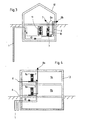
- Fig. 3 shows an example of the use of the device according to the invention in a family home that is heated by a heat pump.
- A is shown Flow circuit 1, in which the heat pump 11 is integrated.
- Connected to the flow circuit 1 is also the Carrier medium fresh air heat exchanger 3. This is in the immediate vicinity Proximity of the ventilation device 10 with which the distribution of fresh air, supply air and Exhaust air is controlled centrally.
- the fresh air 6 is sucked in from outside the building and by means of the Heat exchanger 3 preheated.
- This preheated fresh air is in one the heat exchanger, not shown, using the exhaust air 8a pre-heated the desired room temperature.
- This preheated fresh air 6 is then as supply air 7 via the air distribution device 10 in the living room issued.
- the used air sucked in as exhaust air 8a is after the Has left the heat exchanger for heating the fresh air supplied as exhaust air 8b to the atmosphere surrounding the house 12.
- the system described with FIG. 3 has a central one Carrier medium fresh air heat exchanger 3 and a centrally arranged Ventilation unit 10.
- a decentralized arrangement be provided, using the example of an apartment building with conventional Heating Fig. 4 can be removed.
- each individual room 9a and 9b a separate one Carrier medium fresh air heat exchanger 3 and a separate ventilation device 10 intended.
- Each floor or room 9a, 9b can thus advantageously regardless of the other floor or rooms 9a, 9b be tempered. Otherwise, the mode of operation corresponds to the embodiment 4 that of FIG. 3.
Landscapes
- Engineering & Computer Science (AREA)
- Life Sciences & Earth Sciences (AREA)
- Sustainable Development (AREA)
- Sustainable Energy (AREA)
- Chemical & Material Sciences (AREA)
- Combustion & Propulsion (AREA)
- Mechanical Engineering (AREA)
- General Engineering & Computer Science (AREA)
- Central Air Conditioning (AREA)
- Air Conditioning Control Device (AREA)
- Ventilation (AREA)
Abstract
Description
- 1
- Strömungskreislauf
- 1a, 1b, 1c
- Anschlußkreislauf
- 2a, 2b, 2c
- Strömungskreislauf
- 3
- Wärmetauscher
- 4
- Pumpe
- 5
- Ausgleichsvolumen
- 6
- Frischluft
- 7
- Zuluft
- 8a, 8b
- Abluft
- 9a, 9b, 9c
- Raum
- 10
- Lüftungsgerät
- 11
- Wärmepumpe
- 12
- Haus
Claims (11)
- Verfahren zur Temperierung von Außenluft für die Wohnungsbelüftung, bei dem in einem geschlossenen Strömungskreislauf (1) ein Trägermedium geführt und mittels Erdwärme temperiert wird, von außen angesogene Frischluft (6) in einem Trägermedium-Frischluft-Wärmetauscher (3) vortemperiert und als Zuluft (7) in die zu belüftende Wohnung oder Räume hiervon (9a, 9b, 9c) eingebracht wird.
- Verfahren nach Anspruch 1, dadurch gekennzeichnet, daß die von außen angesogene Luft (6) im Trägermedium-Frischluft-Wärmetauscher (3) vorgewärmt wird.
- Verfahren nach Anspruch 1, dadurch gekennzeichnet, daß die von außen angesogene Luft (6) im Trägermedium- Frischluft- Wärmetauscher (3) gekühlt wird.
- Vorrichtung zur Durchführung des Verfahrens nach einem der Ansprüche 1 bis 3, gekennzeichnet durch wenigstens zwei voneinander unabhängige Strömungskreisläuft (1, 2), die mittels eines Trägermedium-Frischluft-Wärmetauschers (3) wärmeübertragend in Verbindung steht.
- Vorrichtung nach Anspruch 4, dadurch gekennzeichnet, daß der eine Strömungskreislauf (1) geschlossen ausgebildet ist und ein mittels Erdwärme temperierbares Trägermedium führt.
- Vorrichtung nach einem der Ansprüche 4 oder 5, dadurch gekennzeichnet, daß für eine Temperierung des Trägermediums ein zentraler Erdkollektor, eine Erdsonde und/oder ein Grundwasserbrunnen vorgesehen ist.
- Vorrichtung nach einem der Ansprüche 4, 5 oder 6, dadurch gekennzeichnet, daß das Trägermedium eine Flüssigkeit, vorzugsweise Sole ist.
- Vorrichtung nach einem der Ansprüche 4, 5 oder 6, dadurch gekennzeichnet, daß das Trägermedium Grundwasser ist.
- Vorrichtung nach einem der Ansprüche 4 bis 8, dadurch gekennzeichnet, daß der andere Strömungskreislauf (2) offen außen ausgebildet ist und der Zuführung von Frischluft (6) dient.
- Vorrichtung nach einem der Ansprüche 4 bis 9, dadurch gekennzeichnet, daß der Trägermedium-Frischluft-Wärmetauscher (3) ein Flüssigkeit-Luft-Wärmetauscher ist.
- Vorrichtung nach einem der Ansprüche 4 bis 10, dadurch gekennzeichnet, daß der das Trägermedium führende Strömungskreislauf (1) mittels je eines Trägermedium-Frischluft-Wärmetauschers (3) mit einer Vielzahl von Frischluft- Strömungskreislauf (2) wärmeübertragend in Verbindung steht.
Priority Applications (3)
| Application Number | Priority Date | Filing Date | Title |
|---|---|---|---|
| AT02013884T ATE445132T1 (de) | 2002-06-24 | 2002-06-24 | Verfahren sowie vorrichtung zur temperierung von aussenluft für die wohnungsbelüftung |
| EP02013884.8A EP1376020B2 (de) | 2002-06-24 | 2002-06-24 | Verfahren sowie Vorrichtung zur Temperierung von Aussenluft für die Wohnungsbelüftung |
| DE50213901T DE50213901D1 (de) | 2002-06-24 | 2002-06-24 | Verfahren sowie Vorrichtung zur Temperierung von Aussenluft für die Wohnungsbelüftung |
Applications Claiming Priority (1)
| Application Number | Priority Date | Filing Date | Title |
|---|---|---|---|
| EP02013884.8A EP1376020B2 (de) | 2002-06-24 | 2002-06-24 | Verfahren sowie Vorrichtung zur Temperierung von Aussenluft für die Wohnungsbelüftung |
Publications (3)
| Publication Number | Publication Date |
|---|---|
| EP1376020A1 true EP1376020A1 (de) | 2004-01-02 |
| EP1376020B1 EP1376020B1 (de) | 2009-10-07 |
| EP1376020B2 EP1376020B2 (de) | 2014-12-17 |
Family
ID=29716821
Family Applications (1)
| Application Number | Title | Priority Date | Filing Date |
|---|---|---|---|
| EP02013884.8A Expired - Lifetime EP1376020B2 (de) | 2002-06-24 | 2002-06-24 | Verfahren sowie Vorrichtung zur Temperierung von Aussenluft für die Wohnungsbelüftung |
Country Status (3)
| Country | Link |
|---|---|
| EP (1) | EP1376020B2 (de) |
| AT (1) | ATE445132T1 (de) |
| DE (1) | DE50213901D1 (de) |
Cited By (3)
| Publication number | Priority date | Publication date | Assignee | Title |
|---|---|---|---|---|
| CY2452B1 (en) | 2004-05-10 | 2005-06-03 | Marbill Ltd | Method and system for the airconditioning of a building. |
| EP1600700A1 (de) * | 2003-04-07 | 2005-11-30 | Tai-Her Yang | Klimaanlage mit wärmetausch zwischen einer natürlichen wärmequelle und der klimatisierten luft |
| DE102005011700B4 (de) * | 2005-03-11 | 2019-12-24 | Stiebel Eltron Gmbh & Co. Kg | Wärmepumpensystem |
Citations (3)
| Publication number | Priority date | Publication date | Assignee | Title |
|---|---|---|---|---|
| DE2843813A1 (de) * | 1978-10-07 | 1980-04-10 | Reinhold Laroche | Verfahren zur temperierten belueftung von wohn- und geschaeftsraeumen und anlage zur durchfuehrung des verfahrens |
| US4325357A (en) * | 1980-05-12 | 1982-04-20 | Wormser Eric M | Solar energy and ground-water cooling devices |
| DE19950212A1 (de) * | 1999-10-19 | 2001-04-26 | Moser Peter | Lüftungsbox |
-
2002
- 2002-06-24 DE DE50213901T patent/DE50213901D1/de not_active Expired - Lifetime
- 2002-06-24 EP EP02013884.8A patent/EP1376020B2/de not_active Expired - Lifetime
- 2002-06-24 AT AT02013884T patent/ATE445132T1/de active
Patent Citations (3)
| Publication number | Priority date | Publication date | Assignee | Title |
|---|---|---|---|---|
| DE2843813A1 (de) * | 1978-10-07 | 1980-04-10 | Reinhold Laroche | Verfahren zur temperierten belueftung von wohn- und geschaeftsraeumen und anlage zur durchfuehrung des verfahrens |
| US4325357A (en) * | 1980-05-12 | 1982-04-20 | Wormser Eric M | Solar energy and ground-water cooling devices |
| DE19950212A1 (de) * | 1999-10-19 | 2001-04-26 | Moser Peter | Lüftungsbox |
Cited By (3)
| Publication number | Priority date | Publication date | Assignee | Title |
|---|---|---|---|---|
| EP1600700A1 (de) * | 2003-04-07 | 2005-11-30 | Tai-Her Yang | Klimaanlage mit wärmetausch zwischen einer natürlichen wärmequelle und der klimatisierten luft |
| CY2452B1 (en) | 2004-05-10 | 2005-06-03 | Marbill Ltd | Method and system for the airconditioning of a building. |
| DE102005011700B4 (de) * | 2005-03-11 | 2019-12-24 | Stiebel Eltron Gmbh & Co. Kg | Wärmepumpensystem |
Also Published As
| Publication number | Publication date |
|---|---|
| EP1376020B2 (de) | 2014-12-17 |
| EP1376020B1 (de) | 2009-10-07 |
| DE50213901D1 (de) | 2009-11-19 |
| ATE445132T1 (de) | 2009-10-15 |
Similar Documents
| Publication | Publication Date | Title |
|---|---|---|
| AT502029B1 (de) | Einrichtung zur belüftung und beheizung von gebäuden | |
| EP1616133B1 (de) | Fluid-luft-kombiverdampfer und neues schaltkonzept für eine wärmepumpe in einem lüftungsgerät | |
| DE1604205A1 (de) | Klimaanlage | |
| DE202008001537U1 (de) | Niedrigenergiegebäude, insbesondere Treibhaus oder Stallung | |
| DE10118572B4 (de) | Wärmeversorgungssystem | |
| WO2024002855A1 (de) | Zweiverbindungssystem für wärmepumpen und erdwärmekollektoren | |
| EP0041658B1 (de) | Anordnung zum Heizen oder Kühlen von klimatisierten Räumen in Wohnungen, Gewächshäusern oder dergleichen | |
| DE29720577U1 (de) | Wärmepumpen/Klima-Anlage mit Energiereceycling | |
| DE2602479B2 (de) | Wärmerückgewinnungsanlage für mittels einer Wärmepumpe beheizte Gebäude | |
| DE10139065A1 (de) | Vorrichtung zur Gewinnung von Wärmeenergie durch Nutzung der Latentwärme von Wasser und dafür geeigneter Wärmeaustauscher | |
| WO2010089027A1 (de) | Bauwerk und verfahren zum temperieren und belüften des bauwerks | |
| DE3035538A1 (de) | Anordnung zur aufnahme und speicherung von umweltwaerme zwecks beheizung und kuehlung von gebaeuden | |
| DE29706131U1 (de) | Wärmepumpen/Klima-Anlage mit Wärmerückgewinnung | |
| DE2819839A1 (de) | Heiz- und ventilationssystem | |
| EP1376020B2 (de) | Verfahren sowie Vorrichtung zur Temperierung von Aussenluft für die Wohnungsbelüftung | |
| DE19622609A1 (de) | Verfahren zum Betreiben einer Wärmepumpe | |
| DE2608873C3 (de) | Verfahren und Vorrichtung zum Beheizen von Räumen mittels eines Wärmepumpenprozesses | |
| DE19900358A1 (de) | Kombinierte Heizungs-/Lüftungsanlage, insbesondere für Niedrigenergiehäuser | |
| DE102006007848B4 (de) | Anlage zum Erwärmen einer Einrichtung wie einer Halle mit hohem Temperaturniveau, die entfeuchtet werden muss, insbesondere einer Schwimmhalle | |
| EP1163479B1 (de) | Verwendung einer lüftungsanordnung für gebäude | |
| DE4326229A1 (de) | Verfahren zur Temperaturregelung von Räumen in Gebäuden und Einrichtung zur Durchführung des Verfahrens | |
| DE2416294A1 (de) | Vorrichtung zur waermerueckgewinnung | |
| DE3021464C2 (de) | Verfahren und Vorrichtung zum Klimatisieren von der Einwirkung natürlicher Wärmeeinstrahlung ausgesetzten Räumen | |
| DE19861020C1 (de) | Lüftungsanordnung für Gebäude | |
| EP4269890B1 (de) | Verfahren und system zur temperierung eines gebäudes |
Legal Events
| Date | Code | Title | Description |
|---|---|---|---|
| PUAI | Public reference made under article 153(3) epc to a published international application that has entered the european phase |
Free format text: ORIGINAL CODE: 0009012 |
|
| AK | Designated contracting states |
Kind code of ref document: A1 Designated state(s): AT BE CH CY DE DK ES FI FR GB GR IE IT LI LU MC NL PT SE TR |
|
| AX | Request for extension of the european patent |
Extension state: AL LT LV MK RO SI |
|
| 17P | Request for examination filed |
Effective date: 20031205 |
|
| AKX | Designation fees paid |
Designated state(s): AT BE CH CY DE DK ES FI FR GB GR IE IT LI LU MC NL PT SE TR |
|
| 17Q | First examination report despatched |
Effective date: 20070716 |
|
| GRAP | Despatch of communication of intention to grant a patent |
Free format text: ORIGINAL CODE: EPIDOSNIGR1 |
|
| GRAS | Grant fee paid |
Free format text: ORIGINAL CODE: EPIDOSNIGR3 |
|
| GRAA | (expected) grant |
Free format text: ORIGINAL CODE: 0009210 |
|
| AK | Designated contracting states |
Kind code of ref document: B1 Designated state(s): AT BE CH CY DE DK ES FI FR GB GR IE IT LI LU MC NL PT SE TR |
|
| REG | Reference to a national code |
Ref country code: GB Ref legal event code: FG4D Free format text: NOT ENGLISH |
|
| REG | Reference to a national code |
Ref country code: CH Ref legal event code: EP |
|
| REG | Reference to a national code |
Ref country code: IE Ref legal event code: FG4D |
|
| REG | Reference to a national code |
Ref country code: CH Ref legal event code: NV Representative=s name: E. BLUM & CO. AG PATENT- UND MARKENANWAELTE VSP |
|
| REF | Corresponds to: |
Ref document number: 50213901 Country of ref document: DE Date of ref document: 20091119 Kind code of ref document: P |
|
| PG25 | Lapsed in a contracting state [announced via postgrant information from national office to epo] |
Ref country code: SE Free format text: LAPSE BECAUSE OF FAILURE TO SUBMIT A TRANSLATION OF THE DESCRIPTION OR TO PAY THE FEE WITHIN THE PRESCRIBED TIME-LIMIT Effective date: 20091007 Ref country code: PT Free format text: LAPSE BECAUSE OF FAILURE TO SUBMIT A TRANSLATION OF THE DESCRIPTION OR TO PAY THE FEE WITHIN THE PRESCRIBED TIME-LIMIT Effective date: 20100208 Ref country code: FI Free format text: LAPSE BECAUSE OF FAILURE TO SUBMIT A TRANSLATION OF THE DESCRIPTION OR TO PAY THE FEE WITHIN THE PRESCRIBED TIME-LIMIT Effective date: 20091007 Ref country code: ES Free format text: LAPSE BECAUSE OF FAILURE TO SUBMIT A TRANSLATION OF THE DESCRIPTION OR TO PAY THE FEE WITHIN THE PRESCRIBED TIME-LIMIT Effective date: 20100118 |
|
| REG | Reference to a national code |
Ref country code: IE Ref legal event code: FD4D |
|
| PLBI | Opposition filed |
Free format text: ORIGINAL CODE: 0009260 |
|
| PG25 | Lapsed in a contracting state [announced via postgrant information from national office to epo] |
Ref country code: IE Free format text: LAPSE BECAUSE OF FAILURE TO SUBMIT A TRANSLATION OF THE DESCRIPTION OR TO PAY THE FEE WITHIN THE PRESCRIBED TIME-LIMIT Effective date: 20091007 Ref country code: DK Free format text: LAPSE BECAUSE OF FAILURE TO SUBMIT A TRANSLATION OF THE DESCRIPTION OR TO PAY THE FEE WITHIN THE PRESCRIBED TIME-LIMIT Effective date: 20091007 |
|
| PLAX | Notice of opposition and request to file observation + time limit sent |
Free format text: ORIGINAL CODE: EPIDOSNOBS2 |
|
| 26 | Opposition filed |
Opponent name: DANFOSS A/S Effective date: 20100629 |
|
| PG25 | Lapsed in a contracting state [announced via postgrant information from national office to epo] |
Ref country code: GR Free format text: LAPSE BECAUSE OF FAILURE TO SUBMIT A TRANSLATION OF THE DESCRIPTION OR TO PAY THE FEE WITHIN THE PRESCRIBED TIME-LIMIT Effective date: 20100108 |
|
| PLAF | Information modified related to communication of a notice of opposition and request to file observations + time limit |
Free format text: ORIGINAL CODE: EPIDOSCOBS2 |
|
| PG25 | Lapsed in a contracting state [announced via postgrant information from national office to epo] |
Ref country code: MC Free format text: LAPSE BECAUSE OF NON-PAYMENT OF DUE FEES Effective date: 20100630 |
|
| PLBB | Reply of patent proprietor to notice(s) of opposition received |
Free format text: ORIGINAL CODE: EPIDOSNOBS3 |
|
| PG25 | Lapsed in a contracting state [announced via postgrant information from national office to epo] |
Ref country code: CY Free format text: LAPSE BECAUSE OF FAILURE TO SUBMIT A TRANSLATION OF THE DESCRIPTION OR TO PAY THE FEE WITHIN THE PRESCRIBED TIME-LIMIT Effective date: 20091007 |
|
| PG25 | Lapsed in a contracting state [announced via postgrant information from national office to epo] |
Ref country code: LU Free format text: LAPSE BECAUSE OF NON-PAYMENT OF DUE FEES Effective date: 20100624 |
|
| PG25 | Lapsed in a contracting state [announced via postgrant information from national office to epo] |
Ref country code: TR Free format text: LAPSE BECAUSE OF FAILURE TO SUBMIT A TRANSLATION OF THE DESCRIPTION OR TO PAY THE FEE WITHIN THE PRESCRIBED TIME-LIMIT Effective date: 20091007 |
|
| PUAH | Patent maintained in amended form |
Free format text: ORIGINAL CODE: 0009272 |
|
| STAA | Information on the status of an ep patent application or granted ep patent |
Free format text: STATUS: PATENT MAINTAINED AS AMENDED |
|
| 27A | Patent maintained in amended form |
Effective date: 20141217 |
|
| AK | Designated contracting states |
Kind code of ref document: B2 Designated state(s): AT BE CH CY DE DK ES FI FR GB GR IE IT LI LU MC NL PT SE TR |
|
| REG | Reference to a national code |
Ref country code: DE Ref legal event code: R102 Ref document number: 50213901 Country of ref document: DE |
|
| REG | Reference to a national code |
Ref country code: CH Ref legal event code: AELC |
|
| REG | Reference to a national code |
Ref country code: DE Ref legal event code: R102 Ref document number: 50213901 Country of ref document: DE Effective date: 20141217 |
|
| REG | Reference to a national code |
Ref country code: NL Ref legal event code: T3 |
|
| REG | Reference to a national code |
Ref country code: FR Ref legal event code: PLFP Year of fee payment: 14 |
|
| REG | Reference to a national code |
Ref country code: FR Ref legal event code: PLFP Year of fee payment: 15 |
|
| REG | Reference to a national code |
Ref country code: FR Ref legal event code: PLFP Year of fee payment: 16 |
|
| REG | Reference to a national code |
Ref country code: CH Ref legal event code: PFUS Owner name: ZEHNDER GROUP INTERNATIONAL AG, CH Free format text: FORMER OWNER: ZEHNDER VERKAUFS- UND VERWALTUNGS AG, CH |
|
| REG | Reference to a national code |
Ref country code: NL Ref legal event code: PD Owner name: ZEHNDER GROUP INTERNATIONAL AG; CH Free format text: DETAILS ASSIGNMENT: CHANGE OF OWNER(S), MERGE; FORMER OWNER NAME: ZEHNDER VERKAUFS- UND VERWALTUNGS AG Effective date: 20170517 |
|
| REG | Reference to a national code |
Ref country code: GB Ref legal event code: 732E Free format text: REGISTERED BETWEEN 20170817 AND 20170823 |
|
| REG | Reference to a national code |
Ref country code: DE Ref legal event code: R082 Ref document number: 50213901 Country of ref document: DE Representative=s name: STENGER WATZKE RING INTELLECTUAL PROPERTY, DE Ref country code: DE Ref legal event code: R081 Ref document number: 50213901 Country of ref document: DE Owner name: ZEHNDER GROUP INTERNATIONAL AG, CH Free format text: FORMER OWNER: ZEHNDER VERKAUFS- UND VERWALTUNGS-AG, GRAENICHEN, CH Ref country code: DE Ref legal event code: R082 Ref document number: 50213901 Country of ref document: DE Representative=s name: RAUSCH WANISCHECK-BERGMANN BRINKMANN PARTNERSC, DE |
|
| REG | Reference to a national code |
Ref country code: FR Ref legal event code: TP Owner name: ZEHNDER GROUP INTERNATIONAL AG, CH Effective date: 20171009 |
|
| REG | Reference to a national code |
Ref country code: AT Ref legal event code: PC Ref document number: 445132 Country of ref document: AT Kind code of ref document: T Owner name: ZEHNDER GROUP INTERNATIONAL AG, CH Effective date: 20171213 |
|
| REG | Reference to a national code |
Ref country code: DE Ref legal event code: R082 Ref document number: 50213901 Country of ref document: DE Representative=s name: BRINKMANN & PARTNER PATENTANWAELTE PARTNERSCHA, DE Ref country code: DE Ref legal event code: R082 Ref document number: 50213901 Country of ref document: DE Representative=s name: RAUSCH WANISCHECK-BERGMANN BRINKMANN PARTNERSC, DE |
|
| REG | Reference to a national code |
Ref country code: FR Ref legal event code: PLFP Year of fee payment: 17 |
|
| PGFP | Annual fee paid to national office [announced via postgrant information from national office to epo] |
Ref country code: DE Payment date: 20180723 Year of fee payment: 17 Ref country code: IT Payment date: 20180724 Year of fee payment: 17 Ref country code: NL Payment date: 20180719 Year of fee payment: 17 Ref country code: FR Payment date: 20180725 Year of fee payment: 17 |
|
| PGFP | Annual fee paid to national office [announced via postgrant information from national office to epo] |
Ref country code: CH Payment date: 20180719 Year of fee payment: 17 Ref country code: BE Payment date: 20180718 Year of fee payment: 17 Ref country code: GB Payment date: 20180719 Year of fee payment: 17 Ref country code: AT Payment date: 20180720 Year of fee payment: 17 |
|
| REG | Reference to a national code |
Ref country code: DE Ref legal event code: R119 Ref document number: 50213901 Country of ref document: DE |
|
| REG | Reference to a national code |
Ref country code: CH Ref legal event code: PL |
|
| REG | Reference to a national code |
Ref country code: NL Ref legal event code: MM Effective date: 20190701 |
|
| REG | Reference to a national code |
Ref country code: AT Ref legal event code: MM01 Ref document number: 445132 Country of ref document: AT Kind code of ref document: T Effective date: 20190624 |
|
| GBPC | Gb: european patent ceased through non-payment of renewal fee |
Effective date: 20190624 |
|
| REG | Reference to a national code |
Ref country code: BE Ref legal event code: MM Effective date: 20190630 |
|
| PG25 | Lapsed in a contracting state [announced via postgrant information from national office to epo] |
Ref country code: GB Free format text: LAPSE BECAUSE OF NON-PAYMENT OF DUE FEES Effective date: 20190624 Ref country code: IT Free format text: LAPSE BECAUSE OF NON-PAYMENT OF DUE FEES Effective date: 20190624 Ref country code: DE Free format text: LAPSE BECAUSE OF NON-PAYMENT OF DUE FEES Effective date: 20200101 Ref country code: AT Free format text: LAPSE BECAUSE OF NON-PAYMENT OF DUE FEES Effective date: 20190624 Ref country code: NL Free format text: LAPSE BECAUSE OF NON-PAYMENT OF DUE FEES Effective date: 20190701 |
|
| PG25 | Lapsed in a contracting state [announced via postgrant information from national office to epo] |
Ref country code: LI Free format text: LAPSE BECAUSE OF NON-PAYMENT OF DUE FEES Effective date: 20190630 Ref country code: CH Free format text: LAPSE BECAUSE OF NON-PAYMENT OF DUE FEES Effective date: 20190630 Ref country code: BE Free format text: LAPSE BECAUSE OF NON-PAYMENT OF DUE FEES Effective date: 20190630 |
|
| PG25 | Lapsed in a contracting state [announced via postgrant information from national office to epo] |
Ref country code: FR Free format text: LAPSE BECAUSE OF NON-PAYMENT OF DUE FEES Effective date: 20190630 |