EP1375938A1 - Linear motion guide with a ball return passage or ball screw provided with a ball return passage - Google Patents
Linear motion guide with a ball return passage or ball screw provided with a ball return passage Download PDFInfo
- Publication number
- EP1375938A1 EP1375938A1 EP20030014285 EP03014285A EP1375938A1 EP 1375938 A1 EP1375938 A1 EP 1375938A1 EP 20030014285 EP20030014285 EP 20030014285 EP 03014285 A EP03014285 A EP 03014285A EP 1375938 A1 EP1375938 A1 EP 1375938A1
- Authority
- EP
- European Patent Office
- Prior art keywords
- ball
- scoop
- groove
- spacer
- balls
- Prior art date
- Legal status (The legal status is an assumption and is not a legal conclusion. Google has not performed a legal analysis and makes no representation as to the accuracy of the status listed.)
- Granted
Links
- 125000006850 spacer group Chemical group 0.000 claims abstract description 135
- 238000005096 rolling process Methods 0.000 claims abstract description 119
- 230000002093 peripheral effect Effects 0.000 claims description 10
- 230000000052 comparative effect Effects 0.000 description 3
- 239000002184 metal Substances 0.000 description 3
- 230000002411 adverse Effects 0.000 description 2
- 230000007547 defect Effects 0.000 description 2
- 238000004519 manufacturing process Methods 0.000 description 2
- 238000000465 moulding Methods 0.000 description 2
- 239000011347 resin Substances 0.000 description 2
- 229920005989 resin Polymers 0.000 description 2
- 239000000853 adhesive Substances 0.000 description 1
- 230000001070 adhesive effect Effects 0.000 description 1
- 230000002146 bilateral effect Effects 0.000 description 1
- 238000004891 communication Methods 0.000 description 1
- 238000005520 cutting process Methods 0.000 description 1
- 238000013461 design Methods 0.000 description 1
- 238000001746 injection moulding Methods 0.000 description 1
- 238000003780 insertion Methods 0.000 description 1
- 230000037431 insertion Effects 0.000 description 1
- 230000009191 jumping Effects 0.000 description 1
- 239000000314 lubricant Substances 0.000 description 1
- 239000007769 metal material Substances 0.000 description 1
- 238000000034 method Methods 0.000 description 1
- 238000012986 modification Methods 0.000 description 1
- 230000004048 modification Effects 0.000 description 1
- 230000000149 penetrating effect Effects 0.000 description 1
- 239000011295 pitch Substances 0.000 description 1
- 239000000843 powder Substances 0.000 description 1
- 239000004575 stone Substances 0.000 description 1
Images





Classifications
-
- F—MECHANICAL ENGINEERING; LIGHTING; HEATING; WEAPONS; BLASTING
- F16—ENGINEERING ELEMENTS AND UNITS; GENERAL MEASURES FOR PRODUCING AND MAINTAINING EFFECTIVE FUNCTIONING OF MACHINES OR INSTALLATIONS; THERMAL INSULATION IN GENERAL
- F16C—SHAFTS; FLEXIBLE SHAFTS; ELEMENTS OR CRANKSHAFT MECHANISMS; ROTARY BODIES OTHER THAN GEARING ELEMENTS; BEARINGS
- F16C29/00—Bearings for parts moving only linearly
- F16C29/04—Ball or roller bearings
- F16C29/06—Ball or roller bearings in which the rolling bodies circulate partly without carrying load
- F16C29/0633—Ball or roller bearings in which the rolling bodies circulate partly without carrying load with a bearing body defining a U-shaped carriage, i.e. surrounding a guide rail or track on three sides
- F16C29/0635—Ball or roller bearings in which the rolling bodies circulate partly without carrying load with a bearing body defining a U-shaped carriage, i.e. surrounding a guide rail or track on three sides whereby the return paths are provided as bores in a main body of the U-shaped carriage, e.g. the main body of the U-shaped carriage is a single part with end caps provided at each end
- F16C29/0638—Ball or roller bearings in which the rolling bodies circulate partly without carrying load with a bearing body defining a U-shaped carriage, i.e. surrounding a guide rail or track on three sides whereby the return paths are provided as bores in a main body of the U-shaped carriage, e.g. the main body of the U-shaped carriage is a single part with end caps provided at each end with balls
- F16C29/0642—Ball or roller bearings in which the rolling bodies circulate partly without carrying load with a bearing body defining a U-shaped carriage, i.e. surrounding a guide rail or track on three sides whereby the return paths are provided as bores in a main body of the U-shaped carriage, e.g. the main body of the U-shaped carriage is a single part with end caps provided at each end with balls with four rows of balls
-
- F—MECHANICAL ENGINEERING; LIGHTING; HEATING; WEAPONS; BLASTING
- F16—ENGINEERING ELEMENTS AND UNITS; GENERAL MEASURES FOR PRODUCING AND MAINTAINING EFFECTIVE FUNCTIONING OF MACHINES OR INSTALLATIONS; THERMAL INSULATION IN GENERAL
- F16H—GEARING
- F16H25/00—Gearings comprising primarily only cams, cam-followers and screw-and-nut mechanisms
-
- F—MECHANICAL ENGINEERING; LIGHTING; HEATING; WEAPONS; BLASTING
- F16—ENGINEERING ELEMENTS AND UNITS; GENERAL MEASURES FOR PRODUCING AND MAINTAINING EFFECTIVE FUNCTIONING OF MACHINES OR INSTALLATIONS; THERMAL INSULATION IN GENERAL
- F16C—SHAFTS; FLEXIBLE SHAFTS; ELEMENTS OR CRANKSHAFT MECHANISMS; ROTARY BODIES OTHER THAN GEARING ELEMENTS; BEARINGS
- F16C29/00—Bearings for parts moving only linearly
- F16C29/04—Ball or roller bearings
- F16C29/06—Ball or roller bearings in which the rolling bodies circulate partly without carrying load
- F16C29/0602—Details of the bearing body or carriage or parts thereof, e.g. methods for manufacturing or assembly
- F16C29/0609—Details of the bearing body or carriage or parts thereof, e.g. methods for manufacturing or assembly of the ends of the bearing body or carriage where the rolling elements change direction, e.g. end caps
-
- F—MECHANICAL ENGINEERING; LIGHTING; HEATING; WEAPONS; BLASTING
- F16—ENGINEERING ELEMENTS AND UNITS; GENERAL MEASURES FOR PRODUCING AND MAINTAINING EFFECTIVE FUNCTIONING OF MACHINES OR INSTALLATIONS; THERMAL INSULATION IN GENERAL
- F16C—SHAFTS; FLEXIBLE SHAFTS; ELEMENTS OR CRANKSHAFT MECHANISMS; ROTARY BODIES OTHER THAN GEARING ELEMENTS; BEARINGS
- F16C29/00—Bearings for parts moving only linearly
- F16C29/04—Ball or roller bearings
- F16C29/06—Ball or roller bearings in which the rolling bodies circulate partly without carrying load
- F16C29/068—Ball or roller bearings in which the rolling bodies circulate partly without carrying load with the bearing body fully encircling the guide rail or track
- F16C29/0692—Ball or roller bearings in which the rolling bodies circulate partly without carrying load with the bearing body fully encircling the guide rail or track the bearing body encircles a guide rail or track of non-circular cross-section, e.g. with grooves or protrusions, i.e. the linear bearing is suited to transmit torque
- F16C29/0695—Ball or roller bearings in which the rolling bodies circulate partly without carrying load with the bearing body fully encircling the guide rail or track the bearing body encircles a guide rail or track of non-circular cross-section, e.g. with grooves or protrusions, i.e. the linear bearing is suited to transmit torque with balls
-
- F—MECHANICAL ENGINEERING; LIGHTING; HEATING; WEAPONS; BLASTING
- F16—ENGINEERING ELEMENTS AND UNITS; GENERAL MEASURES FOR PRODUCING AND MAINTAINING EFFECTIVE FUNCTIONING OF MACHINES OR INSTALLATIONS; THERMAL INSULATION IN GENERAL
- F16C—SHAFTS; FLEXIBLE SHAFTS; ELEMENTS OR CRANKSHAFT MECHANISMS; ROTARY BODIES OTHER THAN GEARING ELEMENTS; BEARINGS
- F16C33/00—Parts of bearings; Special methods for making bearings or parts thereof
- F16C33/30—Parts of ball or roller bearings
- F16C33/37—Loose spacing bodies
- F16C33/3706—Loose spacing bodies with concave surfaces conforming to the shape of the rolling elements, e.g. the spacing bodies are in sliding contact with the rolling elements
-
- F—MECHANICAL ENGINEERING; LIGHTING; HEATING; WEAPONS; BLASTING
- F16—ENGINEERING ELEMENTS AND UNITS; GENERAL MEASURES FOR PRODUCING AND MAINTAINING EFFECTIVE FUNCTIONING OF MACHINES OR INSTALLATIONS; THERMAL INSULATION IN GENERAL
- F16H—GEARING
- F16H25/00—Gearings comprising primarily only cams, cam-followers and screw-and-nut mechanisms
- F16H25/18—Gearings comprising primarily only cams, cam-followers and screw-and-nut mechanisms for conveying or interconverting oscillating or reciprocating motions
- F16H25/20—Screw mechanisms
- F16H25/22—Screw mechanisms with balls, rollers, or similar members between the co-operating parts; Elements essential to the use of such members
- F16H25/2204—Screw mechanisms with balls, rollers, or similar members between the co-operating parts; Elements essential to the use of such members with balls
- F16H25/2214—Screw mechanisms with balls, rollers, or similar members between the co-operating parts; Elements essential to the use of such members with balls with elements for guiding the circulating balls
- F16H25/2219—Axially mounted end-deflectors
-
- F—MECHANICAL ENGINEERING; LIGHTING; HEATING; WEAPONS; BLASTING
- F16—ENGINEERING ELEMENTS AND UNITS; GENERAL MEASURES FOR PRODUCING AND MAINTAINING EFFECTIVE FUNCTIONING OF MACHINES OR INSTALLATIONS; THERMAL INSULATION IN GENERAL
- F16H—GEARING
- F16H25/00—Gearings comprising primarily only cams, cam-followers and screw-and-nut mechanisms
- F16H25/18—Gearings comprising primarily only cams, cam-followers and screw-and-nut mechanisms for conveying or interconverting oscillating or reciprocating motions
- F16H25/20—Screw mechanisms
- F16H25/22—Screw mechanisms with balls, rollers, or similar members between the co-operating parts; Elements essential to the use of such members
- F16H25/2204—Screw mechanisms with balls, rollers, or similar members between the co-operating parts; Elements essential to the use of such members with balls
- F16H25/2214—Screw mechanisms with balls, rollers, or similar members between the co-operating parts; Elements essential to the use of such members with balls with elements for guiding the circulating balls
- F16H25/2223—Cross over deflectors between adjacent thread turns, e.g. S-form deflectors connecting neighbouring threads
-
- F—MECHANICAL ENGINEERING; LIGHTING; HEATING; WEAPONS; BLASTING
- F16—ENGINEERING ELEMENTS AND UNITS; GENERAL MEASURES FOR PRODUCING AND MAINTAINING EFFECTIVE FUNCTIONING OF MACHINES OR INSTALLATIONS; THERMAL INSULATION IN GENERAL
- F16H—GEARING
- F16H25/00—Gearings comprising primarily only cams, cam-followers and screw-and-nut mechanisms
- F16H25/18—Gearings comprising primarily only cams, cam-followers and screw-and-nut mechanisms for conveying or interconverting oscillating or reciprocating motions
- F16H25/20—Screw mechanisms
- F16H25/22—Screw mechanisms with balls, rollers, or similar members between the co-operating parts; Elements essential to the use of such members
- F16H25/2204—Screw mechanisms with balls, rollers, or similar members between the co-operating parts; Elements essential to the use of such members with balls
- F16H25/2233—Screw mechanisms with balls, rollers, or similar members between the co-operating parts; Elements essential to the use of such members with balls with cages or means to hold the balls in position
- F16H25/2238—Screw mechanisms with balls, rollers, or similar members between the co-operating parts; Elements essential to the use of such members with balls with cages or means to hold the balls in position using ball spacers, i.e. spacers separating the balls, e.g. by forming a chain supporting the balls
-
- Y—GENERAL TAGGING OF NEW TECHNOLOGICAL DEVELOPMENTS; GENERAL TAGGING OF CROSS-SECTIONAL TECHNOLOGIES SPANNING OVER SEVERAL SECTIONS OF THE IPC; TECHNICAL SUBJECTS COVERED BY FORMER USPC CROSS-REFERENCE ART COLLECTIONS [XRACs] AND DIGESTS
- Y10—TECHNICAL SUBJECTS COVERED BY FORMER USPC
- Y10T—TECHNICAL SUBJECTS COVERED BY FORMER US CLASSIFICATION
- Y10T74/00—Machine element or mechanism
- Y10T74/19—Gearing
- Y10T74/19642—Directly cooperating gears
- Y10T74/19698—Spiral
- Y10T74/19702—Screw and nut
- Y10T74/19744—Rolling element engaging thread
- Y10T74/19749—Recirculating rolling elements
- Y10T74/19767—Return path geometry
-
- Y—GENERAL TAGGING OF NEW TECHNOLOGICAL DEVELOPMENTS; GENERAL TAGGING OF CROSS-SECTIONAL TECHNOLOGIES SPANNING OVER SEVERAL SECTIONS OF THE IPC; TECHNICAL SUBJECTS COVERED BY FORMER USPC CROSS-REFERENCE ART COLLECTIONS [XRACs] AND DIGESTS
- Y10—TECHNICAL SUBJECTS COVERED BY FORMER USPC
- Y10T—TECHNICAL SUBJECTS COVERED BY FORMER US CLASSIFICATION
- Y10T74/00—Machine element or mechanism
- Y10T74/19—Gearing
- Y10T74/19642—Directly cooperating gears
- Y10T74/19698—Spiral
- Y10T74/19702—Screw and nut
- Y10T74/19744—Rolling element engaging thread
- Y10T74/19749—Recirculating rolling elements
- Y10T74/19777—Interconnected or cooperating rollers or roller structure
Definitions
- the present invention relates to a circulation member for circulating a number of balls and spacers disposed in a ball rolling passage formed between a track member and a movable member in conformity with a relative motion of the movable member with respect to the track member, and also relates to motion guide device and ball screw provided with such circulation member.
- the applicant of the subject application provided a circulation member such as shown in FIG. 20 applied to a ball screw, which is disclosed in Japanese Patent Application No. HEI 10-180767.
- a ball screw is formed with a ball rolling groove, and balls 1 rolling along the ball rolling groove contact both edge portions 3a, 3b of a scoop-up groove 3 formed in a circulation member 2 and are then scooped from the ball rolling groove 3 in an embraced fashion.
- scoop-up groove 3 is formed in the circulation member 2
- an impact force is substantially not applied to the circulation member 2, and therefore, it becomes possible to rotate a screw shaft at high speed to thereby move the balls 1 also at high speed.
- Such circulation member 2 may be functionally sufficient to act only to circulate the balls 1.
- spacers are disposed between the balls 1 for preventing friction or like.
- Such a spacer has substantially cylindrical shape having a diameter smaller than that of the ball 1 and is provided, at its both end portions in the ball advancing direction, with recesses in conformity with the spherical shape of the ball.
- the ball 1 When scooping the ball 1 and the spacer by using the circulation member of the conventional structure mentioned above, for example, because the ball 1 has a spherical surface, the ball 1 is embraced and scooped by both side edge portions 3a, 3a of the scoop-up groove 3. In a case where there exists a small gap between the adjacent balls 1, 1, the spacer put between the balls 1, 1 may be also scooped together with the balls 1.
- An object of the present invention is therefore to substantially eliminate defects or inconveniences encountered in the prior art and to provide a circulation member capable of surely scooping a spacer as well as a ball even in an arrangement that a gap exist between balls, for example, of a ball screw.
- Another object of the present invention is to provide a ball screw and a motion guide device provided with an improved circulation member mentioned above.
- a circulation member formed with a scoop-up groove for scooping the ball and a spacer scoop-up portion by contacting the spacer without contacting the ball.
- the circulation member for achieving the above objects is a circulation member for circulating a number of balls and a number of spacers, each spacer being disposed between the balls, which are arranged in a ball rolling groove formed between a track member and a movable member, in accordance with a relative motion of the movable member with respect to the track member, wherein the circulation member is provided with a scoop-up groove for scooping the balls by contacting the ball rolling in the ball rolling passage at both side edge portions of the scoop-up groove and is also provided with a spacer scoop-up portion which contacts and scoops the spacer moving in the ball rolling passage without contacting the balls.
- the ball rolling on the ball rolling passage is embraced by both side edge portions of the scoop-up groove formed in the circulation member and is then scooped.
- the spacer can be scooped by the spacer scoop-up portion. Also, since the spacer scoop-up portion does not contact the balls being scooped by the scoop-up groove, the spacer scoop-up portion will not be damaged.
- the spacer scoop-up portion is formed with an escape surface which is apart from a track of the ball scooped by the scoop-up groove and contacts the spacer, thus contacting only the spacer without contacting the ball.
- a ball screw comprising:
- the spacer scoop-up portion is also formed with an escape surface which is apart from a track of the ball scooped by the scoop-up groove and contacts the spacer.
- the circulation member has a linear passage having a circular section for linearly moving the ball scooped by the scoop-up groove, and the spacer scoop-up portion is formed at a bottom portion of the scoop-up groove and is formed with an escape surface which is inclined by a predetermined angle with respect to an inner peripheral surface of the linear passage in a sectional area including a center line of the linear passage.
- a motion guide device comprising:
- the circulation member has an improved structure of spacer scoop-up portion, so that the ball and the spacer can be surely scooped without damaging the constitutional elements.
- FIG. 1 shows a ball screw provided with a circulation member according to the first embodiment of the present invention.
- a ball screw 8 is composed of a screw shaft 9 formed with a spiral ball rolling groove 9a formed on an outer peripheral surface thereof and a nut 10 mounted to the screw shaft 9.
- the spiral ball rolling groove 9a is formed by a grinding or rolling working so as to have a constant lead and approximately semi-circular section.
- the nut 10 is formed, on its inner peripheral surface, with a spiral loaded ball rolling groove 10a corresponding to the ball rolling groove 9a of the screw shaft 9.
- the nut 10 generally has a cylindrical shape and the nut 10 is provided, at its one end, with a flanged potion 14 for mounting the ball screw 8 to a machine or like.
- the spiral loaded ball rolling groove 10a of the nut 10 is formed so as to have an approximately semi-circular section of the shape corresponding to the ball rolling groove 9a of the screw shaft 9.
- the nut 10 is formed with insertion holes, at plural portions, for inserting leg portions 12b, 12b of a circulation member 12.
- the ball rolling groove 9a of the screw shaft 9 and the loaded ball rolling groove 10a formed on the nut 10 constitute, in their combination, a ball rolling passage in which a number of balls 11, 11, --- are accommodated and spacers 16, 16, --- are also accommodated to prevent the balls 11 from contacting each other.
- the nut 10 is mounted with, for example, two circulation members 12, 12, which are called "return pipes".
- the circulation member 12 constitutes a non-loaded return passage communicating one end of the ball rolling passage with the other one end thereof so that a number of balls 11, 11, --- and spacers 16, 16, --- circulate in accordance with the relative motion of the nut 10 with respect to the screw shaft 9.
- the circulation member 12 has a gate shape having a central portion 12a and a pair of leg portions 12b, 12b extending from both side end portions of the central portion 12a. These leg portions 12b, 12b are inserted into the ball rolling passage with an interval of several pitches, and the circulation member 12 is fastened to the nut 10 by means of bolts 13 or like.
- the circulation member 12 is disposed so that center lines 19, 19 of the inner peripheries of the paired leg portions 12b, 12b are positioned to the tangential direction of the center line 18 of the spiral ball track as shown in FIG. 2B, and the leg portions 12b, 12b are inclined in directions different from each other in conformity with lead angles of the center line 18.
- the ball 11 can be scooped in the tangential direction and lead angle direction of the track center line 18. That is, the ball 11 can be scooped up along its rolling (advancing) direction. Therefore, no forcible force is not applied to the leg portions 12b, 12b at the time of scooping the ball 11.
- the circulation member 12 is divided into two sections or parts along its axial direction as a pair of divided bodies 20, 20, which are then jointed by means of heat calking, fusing, bonding or like process or by using fastening means, adhesive sheet, clip or like.
- each of the leg portions 12b has a linear passage 21, having a circular section, for substantially linearly moving the ball 11.
- the center line 19 of the inner periphery of this linear passage 21 is arranged in the tangential direction of the ball track center line 18 as shown in FIG. 2.
- the leg portion 12b has a front end extending to the position at which the ball track center line 18 and the center line 19 of the linear passage 21 contact each other, and at a portion near the front end of the leg portion 12 is formed with a scoop-up groove 22 for scooping the ball 11.
- the radius R1 of curvature of the scoop-up groove 22 viewed from the axial direction of the screw shaft 9 is designed to be slightly smaller than the radius R2 of curvature of the track center line 18 of the ball 11 and slightly larger than the outer diameter R3 of the screw shaft 9. Further, the scoop-up groove 22 has a lateral width gradually reduced towards the deep direction of the circulation member 12.
- a spacer scoop-up portion 23 is formed at the bottom portion of the scoop-up groove 22.
- the spacer scoop-up portion 23 is formed with an escape surface 24 so as to be apart from the track of the ball 22 scooped by the scoop-up groove 22 and to contact the spacer 16.
- the escape surface 24 of the spacer scoop-up portion 23 is inclined by a predetermined angle ⁇ with respect to the inner peripheral surface 25 of the linear passage 21.
- a boundary portion 26 is formed between the inner peripheral surface 25 of the linear passage 21 and the escape surface 24 of the spacer scoop-up portion 23. This escape surface 24 can contact the spacer 16 without contacting the ball 11 and scoop the spacer 16 moving in the ball rolling passage.
- the ball scoop-up groove 22 has a width gradually reduced towards inward the circulation member 12, and the ball 11 can be scooped by the contact of both the side edges of the scoop-up groove 22 to the ball 11. Furthermore, in this embodiment, the spacer scoop-up portion 23 is formed at the bottom of the scoop-up groove 22 so as to guide the spacers 16, 16, --- disposed between the balls 11, 11, --- into the circulation member 12.
- the slide mold is inserted into a lateral pair of mold halves.
- the scoop-up grooves 22 and the spacer scoop-up portions 23 are formed to the leg portions 12b, 12b.
- the slide mold is slid in the opposing direction.
- the scoop-up grooves 22 and the spacer scoop-up portions having complicated structures can be manufactured, as well as the inner peripheral surfaces of the leg portions 12b, 12b.
- FIG. 4 The ball scoop-up state by the scoop-up groove 22 is shown in FIG. 4, in which the spacers 16 and the scoop-up portions 23 are removed for the sake of easy understanding of the description for scooping the ball 11 by the scoop-up groove 22.
- the circulation member 12 has an inner diameter, which is slightly larger than an outer diameter of the ball 11 so that the ball 11 can pass the circulation member 12 even in a case where lubricant or like adheres to the ball 11 or the circulation member 12 is slightly displaced.
- the ball 11 is scooped at after the shifting by an angle ⁇ in the screw shaft side and not in the tangential direction of the track center line 18 of the ball 11.
- the line L denotes the track of the center of the ball 11.
- the ball 11 can be scooped by both the edge portions of the scoop-up groove 22,a load caused at the time when the ball 11 contacts the scoop-up groove 22 can be significantly reduced.
- the present invention has been conceived to overcome such inconvenience and provides a screw shaft capable of being rotated at a high speed by forming the scoop-up groove 22 to the circulation member 12. According to the present invention, as mentioned before, since the ball can be scooped by both the edge portions of the scoop-up groove 22, there is no need for forming the tongue portion as in the conventional structure.
- the spacer scoop-up portion 23 acts to scoop up only the spacer 16 and has an outer shape similar to a shape of the tongue portion, which scoops the ball in the return pipe, in the conventional structure.
- the most essential difference of the present invention from the conventional structure resides in the presence of the escape surface 24.
- the tongue portion of the conventional return pipe is formed by cutting or grinding, for example, metal tube or grinding stone.
- an escape surface (such as escape surface 24 in this embodiment) having a predetermined inclination ⁇ with respect to the linear passage is never formed in the return pipe. Since the escape surface 24 is inclined by the predetermined angle of ⁇ , a proj ecting amount from the bottom of the scoop-up groove 22 is made smaller than that of the tongue portion.
- FIG. 5 shows a comparison of gaps between the scoop-up groove 22 and the screw shaft 9 in the case of the circulation member 12 provided with the scoop-up portion 23 and in the case of a circulation member 27 provided with no scoop-up portion. Further, it is to be noted that, in order to observe the gaps, in this FIG. 5, wall sections of the circulation members 12 and 27 on the side opposing to the scoop-up grooves 22 are eliminated in the illustration.
- the balls 11 are scooped by the scoop-up grooves 22 positioned on the sides opposing to the illustrated state.
- a relatively large gap S appears between the scoop-up groove 22 and the screw shaft 9, and there is a fear that the spacer 16 dropping off from the ball 11 is adversely engaged with this space S.
- the spacer scoop-up portion 23 is formed, such space S can be clogged by the spacer scoop-up portion 23.
- the ball 11 is scooped up in the manner of being embraced with both the edge portions of the scoop-up groove 22 (FIG. 6). Furthermore, the spacer 16 can be surely scooped up by the escape surface 24 formed to the spacer scoop-up portion 23 contacting the spacer 16 even if the distance between the adjacent balls 11 is widened and the spacer 16 comes off from the moving passage.
- the spacer 16 does not always contact the spacer scoop-up portion 23, and only in the case that the distance between the balls 11 is widened and the spacer 16 tends to come off from its track, the spacer 16 contacts the spacer scoop-up portion 23. In the other cases, the spacers 16 are moved together with the balls 11. Further, the spacer scoop-up portion 23 does not contact the ball 11 at the time when the ball 11 is scooped up, thus being not damaged or broken.
- FIG. 8 represents a ball screw of end-cap structure provided with a circulation member according to the second embodiment of the present invention.
- the ball screw of this embodiment comprises a screw shaft 34 formed with a ball rolling groove 34a and a nut 31 composed of a nut body 32 formed with a ball rolling groove and side lids as end caps 33, 33 mounted to both ends of the nut body 32.
- the nut body 32 is formed with the ball rolling groove and a ball return passage, and the side lids 33, 33 are formed with communication passages each communicating the ball rolling groove and the return passage.
- the circulation member is mounted to each of the side lids 33, 33 so as to act to scoop the balls 11, 11, --- and the spacers 16, 16, ---disposed between the balls.
- FIG. 9 shows the assembled state of the side lid 33 and the circulation member 35.
- the circulation member 35 is mounted inside the side lid 33 and fixed to the nut body 32 by means of bolt or like.
- the circulation member 35 may have a various outer appearances in accordance with a mounting condition to the side lid 33.
- the circulation member 35 is provided with a ball scoop-up groove 36 which contacts and then scoops the ball 11 rolling in the ball rolling passage at its both side edge portions.
- the ball scoop-up groove 36 is formed, at its bottom portion, with a spacer scoop-up portion 37 for contacting and scooping the spacer 16 in the ball rolling groove without contacting the ball 11.
- the spacer scoop-up portion 37 is formed with an escape surface 38 positioned apart from the ball rolling track and contacting the spacer 16.
- the circulation member 35 is formed with a linear passage 39, having a circular section, for moving substantially linearly the ball 11 scooped by the scoop-up groove 36. Further, in the sectional area including the center line of the linear passage 39, the escape surface 38 of the spacer scoop-up portion 37 is inclined by a predetermined angle ⁇ with respect to the inner peripheral surface 40 of the linear passage 39. According to this embodiment, the spacer 16 can be scooped up by the escape surface 38 even in the case where the distance between the adjacent balls 11, 11 is widened and the spacer 16 is come off from the moving track.
- FIG. 11 also represents a ball screw 41 provided with a circulation member of deflector structure type according to another embodiment of the present invention.
- This circulation member 42 is formed with a ball return groove having approximately S-shape.
- the ball return groove has a most recessed portion at the central portion of the circulation member 42 so that the ball 11 and the spacer 16 advancing in the ball return groove can jump over the outer peripheral portion of the screw shaft 41.
- the circulation member 42 i.e., deflector, acts to forcibly push the ball rolling on the ball rolling groove 41a from its lateral side so as to jump the ball over the outer periphery of the screw shaft 41. Further, a spacer scoop-up portion for scooping only the spacer 16 by contacting it without contacting the ball 11 is formed to the circulation member 42. In this deflector type circulation member 42, the escape surface formed to the scoop-up portion has a three-dimensional shape apart from the three-dimensional ball track.
- the present invention further provides a linear motion guide provided with a circulation member according to the third embodiment with reference to FIG. 12.
- the linear motion guide of this embodiment is, for example, a device for guiding a movable member or body such as table on a stationary member such as bed or saddle.
- the linear motion guide comprises a track rail 51 disposed on a stationary member and having a longitudinal extension, and a slide member assembled with the track rail 51 to be relatively movable.
- the track rail 51 is formed with a ball rolling groove 51a formed along the longitudinal direction thereof and the slide member is also formed with a loaded ball rolling groove so as to correspond to the ball rolling groove 51a formed to track rail 51.
- the linear motion guide further comprises a number of balls disposed in a ball rolling passage formed by, in combination, the ball rolling groove 51a of the track rail 51 and the loaded ball rolling groove formed to the slide member 52, a number of spacers disposed between the balls, and circulation members 53, 53, provided for the slide member 52, for circulating the balls and the spacers in conformity with the relative motion of the slide member 52 with respect to the track rail 51.
- the track rail 51 has an elongated scale so as to provide, for example, a rectangular shape in section.
- the ball rolling groove 51a constitutes a track for ball rolling, and a plurality of rows of ball rolling grooves 51a may be formed in accordance with the object on use of the linear motion guide.
- the track rail 51 has a linear structure, but it may have a curved rail structure.
- the track rail 51 has screw holes to which screws are fastened so as to secure the track rail 51 to the stationary member.
- the slide member 52 comprises a block body 54 and end plates as the circulation members 53, 53 disposed both end portions of the block body 54.
- the circulation members 53, 53 are formed with U-shaped direction changing passage for changing the rolling direction of the ball.
- the block body 54 of the slide member 52 is a ⁇ -shaped member having a flat horizontal portion 54a opposing to the upper surface of the track rail 51, when assembled, and a pair of support leg (skirt) portions 54b,54b opposing to the bilateral side surfaces of the track rail 51.
- Loaded ball rolling grooves are formed to the inside surfaces of the block body 54 so as to oppose to the ball rolling grooves 51a, 51a formed to the outside surface of the track rail 51.
- Ball return passages are also formed to the block body 54, as bores, in parallel to the ball rolling grooves 51a. The ball rolling passage and the ball return passage are communicated by means of the direction changing passage formed to the circulation member 53.
- a plurality of fastening holes are formed to the upper surface of the block body 54 for fastening and securing an object to be guided to the block body 54 by means of screws or bolts.
- FIG. 13 is a perspective view of a portion of the circulation member 53 and FIG. 14 is a sectional view showing the direction changing passage 55 formed to the circulation member 53.
- the circulation member 53 is formed with, as shown, the ball rolling direction changing passage 55 communicating the ball return passage 56 and the ball rolling passage 57. More specifically, the circulation member is formed with an outer periphery guide portion 58 constituting the outer periphery of the direction changing passage 55 and, on the other hand, the block body 54 is formed with an arch-shaped inner periphery guide portion 59 constituting the inner periphery of the direction changing passage 55.
- a ball scoop-up groove 60 is formed to the lower portion of the direction changing passage 55 of the circulation member 53 for contacting and then scooping the ball in the ball rolling passage 57 by both side edge portions of the groove 60.
- the scoop-up groove 60 is formed on one flat surface, in parallel to the track rail 51, on the side of the track rail 51 more than the center line 63 of the direction changing passage 55.
- the scoop-up groove 60 has a horizontal width gradually reduced towards the ball advancing direction.
- the ball scooping manner of this scoop-up groove 60 is substantially the same as that of the former embodiment.
- a spacer scoop-up portion 62 for contacting and then scooping the spacer without contacting the ball in the ball rolling passage 57.
- the spacer scoop-up portion 62 has an escape surface 61 apart from the track 64 of the ball scooped by the scoop-up groove 60 but contacting the spacer.
- FIG. 15 shows the track of the ball 11 scooped by the scoop-up groove 60.
- the direction changing passage 55 of the circulation member 53 is bent in a circular-arc shape.
- the track 66 of the center of the ball 11 passes slightly outside the center line 63 of the direction changing passage. Therefore, the escape surface 61 of the spacer scoop-up portion 62 is formed in consideration of this track of the ball 11 so as not to contact the ball.
- This escape surface 61 may have a curved shape as shown in FIG. 15 as well as linear shape.
- FIG. 16 shows the scooping state of the ball 11 by the scoop-up groove and the scooping state of the spacer 16 by the spacer scoop-up portion 62.
- the ball 11 is first embraced and then scooped by both the edge portions of the scoop-up groove 60. Even if the distance between the balls 11 and the spacer 16 tends to come off from the track, the spacer scoop-up portion 62 contacting the ball 11 can scoop the ball 11.
- FIGs. 17 and 18 An example provided with no spacer scoop-up portion is shown in FIGs. 17 and 18 for comparison.
- the ball 11 having a spherical outer surface is scooped by both the edge portions of the scoop-up groove 60 in the embraced manner.
- the spacer 16 has a flat end shape, and in the case when the distance between the balls 11, 11 is widened and the spacer 16 tends to come off from the track, there may cause a fear that the flat end portion of the spacer 16 adversely engages with the scoop-up groove 60, thus being inconvenient.
- FIG. 19 also shows an example of a ball spline provided with the circulation member according to the present invention.
- the ball spline is composed of a spline shaft 71 as track rail and an outer sleeve 72 as a slide member mounted to the spline shaft 71 through a number of balls 11, 11 --- disposed therebetween.
- the spline shaft 71 has a columnar structure having true circularity and has an outer surface formed as a ball track on which a ball rolling groove 71a so as to extend its axial direction.
- the outer sleeve 72 mounted to the spline shaft 71 is formed with a loaded ball rolling groove corresponding to the ball rolling groove 71a so as to constitute a ball rolling passage as a ball circulation passage in form of circuit.
- a number of balls 11, 11, --- and spacers 16, 16, --- are accommodated so as to circulate therein in accordance with the relative linear motion of the outer sleeve 72 with respect to the spline shaft 71. That is, the ball rolling passage 73 is formed by the ball rolling groove 71a of the spline shaft 71 and the loaded ball rolling groove of the outer sleeve 72.
- the outer sleeve 72 is mounted with a circulation member 75 as a retainer for arranging and retaining the balls 11, 11, --- in the axial direction of the spline shaft 71.
- the circulation member 75 as a retainer is integrally mounted to the outer sleeve 72 and has an inner hollow cylindrical structure into which the spline shaft 71 is disposed in a penetrating manner.
- the circulation member 75 has an outer surface to which the circuit-formed ball circulation passage is formed. According to this circulation member 75, the balls 11, 11, --- rolling on the ball rolling passage 73 are held from both sides between the outer sleeve 72 and the spline shaft 71 and the balls 11, 11, 11, --- rolling on the loaded return passage 74 are held between the outer sleeve 72 and the passage 74 to thereby prevent the balls 11, 11, --- from coming off at the time when the outer sleeve 72 is withdrawn from the spline shaft 71.
- a ball scoop-up groove for scooping the balls 11, 11, --- rolling on the ball rolling passage 73 is formed to the circulation member 75, which may also be formed with a spacer scoop-up portion for scooping us the spacers 16.
- a number of spacers arranged independently between the adjacent balls may be connected in series by using a band or belt member.
- the track rail of the motion guide device may be formed to provide a curved structure in place of the linear structure.
Landscapes
- Engineering & Computer Science (AREA)
- General Engineering & Computer Science (AREA)
- Mechanical Engineering (AREA)
- Transmission Devices (AREA)
- Bearings For Parts Moving Linearly (AREA)
Abstract
Description
- The present invention relates to a circulation member for circulating a number of balls and spacers disposed in a ball rolling passage formed between a track member and a movable member in conformity with a relative motion of the movable member with respect to the track member, and also relates to motion guide device and ball screw provided with such circulation member.
- The applicant of the subject application provided a circulation member such as shown in FIG. 20 applied to a ball screw, which is disclosed in Japanese Patent Application No. HEI 10-180767.
- With reference to FIG. 20, a ball screw is formed with a ball rolling groove, and
balls 1 rolling along the ball rolling groove contact bothedge portions groove 3 formed in acirculation member 2 and are then scooped from theball rolling groove 3 in an embraced fashion. In the case where scoop-up groove 3 is formed in thecirculation member 2, an impact force is substantially not applied to thecirculation member 2, and therefore, it becomes possible to rotate a screw shaft at high speed to thereby move theballs 1 also at high speed. -
Such circulation member 2 may be functionally sufficient to act only to circulate theballs 1. However, there are many cases where spacers are disposed between theballs 1 for preventing friction or like. Such a spacer has substantially cylindrical shape having a diameter smaller than that of theball 1 and is provided, at its both end portions in the ball advancing direction, with recesses in conformity with the spherical shape of the ball. - When scooping the
ball 1 and the spacer by using the circulation member of the conventional structure mentioned above, for example, because theball 1 has a spherical surface, theball 1 is embraced and scooped by bothside edge portions up groove 3. In a case where there exists a small gap between theadjacent balls balls balls 1. - However, as shown in FIGs. 21 and 22, in a case where the
spacer 4 freely moves between theadjacent balls spacer 4 engages with theside edge portions up groove 3 because thespacer 4 has nearly flat end portions in the advancing direction, thus being inconvenient. - An object of the present invention is therefore to substantially eliminate defects or inconveniences encountered in the prior art and to provide a circulation member capable of surely scooping a spacer as well as a ball even in an arrangement that a gap exist between balls, for example, of a ball screw.
- Another object of the present invention is to provide a ball screw and a motion guide device provided with an improved circulation member mentioned above.
- These and other obj ects can be achieved according to the present invention by providing, in a general aspect, a circulation member formed with a scoop-up groove for scooping the ball and a spacer scoop-up portion by contacting the spacer without contacting the ball.
- That is, in one main aspect, the circulation member for achieving the above objects is a circulation member for circulating a number of balls and a number of spacers, each spacer being disposed between the balls, which are arranged in a ball rolling groove formed between a track member and a movable member, in accordance with a relative motion of the movable member with respect to the track member, wherein the circulation member is provided with a scoop-up groove for scooping the balls by contacting the ball rolling in the ball rolling passage at both side edge portions of the scoop-up groove and is also provided with a spacer scoop-up portion which contacts and scoops the spacer moving in the ball rolling passage without contacting the balls.
- According to this aspect, the ball rolling on the ball rolling passage is embraced by both side edge portions of the scoop-up groove formed in the circulation member and is then scooped. In such operation, even if the gap between the balls is widened and the spacer tends to come off from a track of the ball, the spacer can be scooped by the spacer scoop-up portion. Also, since the spacer scoop-up portion does not contact the balls being scooped by the scoop-up groove, the spacer scoop-up portion will not be damaged.
- In a preferred embodiment of this aspect, the spacer scoop-up portion is formed with an escape surface which is apart from a track of the ball scooped by the scoop-up groove and contacts the spacer, thus contacting only the spacer without contacting the ball.
- In another aspect of the present invention, there is provided a ball screw comprising:
- a screw shaft formed, on an outer periphery thereof, with a spiral ball rolling groove;
- a nut assembled with the screw shaft and formed, on an inner periphery thereof, with a spiral loaded ball rolling groove so as to oppose to the ball rolling groove formed on the screw shaft to thereby form a ball rolling passage;
- a number of balls disposed in the ball rolling passage;
- a number of spacers disposed between the balls in the ball rolling passage; and
- a circulation member for circulating a number of balls and spacers, each spacer being disposed between the balls in accordance with a relative motion of the nut with respect to the screw shaft, wherein the circulation member is provided with a scoop-up groove for scooping the balls by contacting the ball rolling in the ball rolling passage at both side edge portions of the scoop-up groove and is also provided with a spacer scoop-up portion which contacts and scoops the spacer moving in the ball rolling passage without contacting the balls.
-
- In preferred embodiments of this aspect, the spacer scoop-up portion is also formed with an escape surface which is apart from a track of the ball scooped by the scoop-up groove and contacts the spacer.
- The circulation member has a linear passage having a circular section for linearly moving the ball scooped by the scoop-up groove, and the spacer scoop-up portion is formed at a bottom portion of the scoop-up groove and is formed with an escape surface which is inclined by a predetermined angle with respect to an inner peripheral surface of the linear passage in a sectional area including a center line of the linear passage.
- In a further aspect of the present invention, there is also provided a motion guide device comprising:
- a track rail formed with a ball rolling groove;
- a slide member mounted to the track rail to be relatively movable with respect thereto and is formed with a loaded ball rolling groove so as to oppose to the ball rolling groove of the track rail to thereby form a ball rolling passage;
- a number of balls disposed in the ball rolling passage;
- a number of spacers disposed between the balls in the ball rolling passage; and
- a circulation member for circulating a number of balls and spacers, each spacer being disposed between the balls in accordance with a relative motion of the slide member with respect to the track rail, wherein the circulation member is provided with a scoop-up groove for scooping the balls by contacting the ball rolling in the ball rolling passage at both side edge portions of the scoop-up groove and is also provided with a spacer scoop-up portion which contacts and scoops the spacer moving in the ball rolling passage without contacting the balls.
-
- According to the ball screw and the motion guide device, the circulation member has an improved structure of spacer scoop-up portion, so that the ball and the spacer can be surely scooped without damaging the constitutional elements.
- The nature and further characteristic features will be made more clear from the following descriptions made with reference to the accompanying drawings.
- In the accompanying drawings:
- FIG. 1 is a perspective view, partially in section, of a ball screw provided with a circulation member according to a first embodiment of the present invention;
- FIG. 2 shows the circulation member and includes FIG. 2A being a plan view of the circulation member, FIG. 2B being a side view thereof as viewed from an axial direction of a screw shaft of the ball screw, FIG. 2C being a side view thereof as viewed from a direction perpendicular to the axis of the screw shaft and FIG. 2D being a front view thereof;
- FIG. 3 shows a leg portion of the circulation member and includes FIG. 3A being a sectional view thereof indicating a radius of curvature of a scoop-up groove and FIG. 3B showing a sectional view thereof indicating an inclination (inclining angle) of an escape surface;
- FIG. 4 is an illustration showing a ball scooping state by the scoop-up groove;
- FIG. 5 is an illustration, in an enlarged scale, showing a comparison of gaps between the scoop-up groove and the screw shaft in a case of a circulation member provided with a scoop-up portion and in a case of a circulation member provided with no scoop-up portion;
- FIG. 6 is an illustration showing a ball scooping state by the scoop-up portion;
- FIG. 7 is an illustration showing a spacer scooping state by a spacer scooping portion;
- FIG. 8 is a perspective view, partially in section, showing an end-cap type ball screw provided with a circulation member according to a second embodiment of the present invention;
- FIG. 9 shows a combination of a side lid and the circulation member of the second embodiment and includes FIG. 9A showing a state viewed from the axial direction of the screw shaft and FIG. 9B showing a state viewed from the side of the screw shaft;
- FIG. 10 is an illustration showing the circulation member of the second embodiment;
- FIG. 11 is a perspective view showing one example of a deflector type ball screw provided with the circulation member of the present invention;
- FIG. 12 is a perspective view of a linear motion guide device provided with a circulation member according to a third embedment of the present invention;
- FIG. 13 is a perspective view showing the circulation member;
- FIG. 14 is a sectional view of the circulation member;
- FIG. 15 is an illustration showing a track of the ball scooped by the scoop-up groove;
- FIG. 16 is an illustration showing a ball scooping state by the scoop-up groove and a spacer scooping state by the spacer scoop-up portion;
- FIG. 17 is an illustration, comparative with FIG. 16, provided with no spacer scooping portion;
- FIG. 18 is a perspective view, comparative with FIG. 16, provided with no spacer scooping portion;
- FIG. 19 is a perspective view of a ball spline provided with the circulation member of the present invention;
- FIG. 20 is a perspective view of a ball screw provided with a circulation member of conventional structure;
- FIG. 21 is an illustration, viewed from the axial direction of a screw shaft, showing a state that a ball is engaged with the scoop-up groove; and
- FIG. 22 is an illustration, viewed from the front side of the scoop-up groove, showing a state that a gap grows between adjacent balls.
-
- Preferred embodiments of the present invention will be described hereunder in detail in conjunction with the accompanying drawings.
- FIG. 1 shows a ball screw provided with a circulation member according to the first embodiment of the present invention.
- With reference to FIG. 1, a
ball screw 8 is composed of ascrew shaft 9 formed with a spiralball rolling groove 9a formed on an outer peripheral surface thereof and anut 10 mounted to thescrew shaft 9. The spiralball rolling groove 9a is formed by a grinding or rolling working so as to have a constant lead and approximately semi-circular section. - On the other hand, the
nut 10 is formed, on its inner peripheral surface, with a spiral loadedball rolling groove 10a corresponding to theball rolling groove 9a of thescrew shaft 9. Thenut 10 generally has a cylindrical shape and thenut 10 is provided, at its one end, with aflanged potion 14 for mounting theball screw 8 to a machine or like. The spiral loadedball rolling groove 10a of thenut 10 is formed so as to have an approximately semi-circular section of the shape corresponding to theball rolling groove 9a of thescrew shaft 9. - The
nut 10 is formed with insertion holes, at plural portions, for insertingleg portions circulation member 12. - The
ball rolling groove 9a of thescrew shaft 9 and the loadedball rolling groove 10a formed on thenut 10 constitute, in their combination, a ball rolling passage in which a number ofballs spacers balls 11 from contacting each other. - In this first embodiment, the
nut 10 is mounted with, for example, twocirculation members circulation member 12 constitutes a non-loaded return passage communicating one end of the ball rolling passage with the other one end thereof so that a number ofballs spacers nut 10 with respect to thescrew shaft 9. - The
circulation member 12 has a gate shape having acentral portion 12a and a pair ofleg portions central portion 12a. Theseleg portions circulation member 12 is fastened to thenut 10 by means ofbolts 13 or like. - With reference to FIG. 2 (FIGs. 2A to 2D), the
circulation member 12 is disposed so thatcenter lines leg portions center line 18 of the spiral ball track as shown in FIG. 2B, and theleg portions center line 18. - According to such arrangement of the center lines of the
leg portions ball 11 can be scooped in the tangential direction and lead angle direction of thetrack center line 18. That is, theball 11 can be scooped up along its rolling (advancing) direction. Therefore, no forcible force is not applied to theleg portions ball 11. - The
circulation member 12 is divided into two sections or parts along its axial direction as a pair of dividedbodies - Next, with reference to FIG. 3, each of the
leg portions 12b has alinear passage 21, having a circular section, for substantially linearly moving theball 11. As mentioned above, thecenter line 19 of the inner periphery of thislinear passage 21 is arranged in the tangential direction of the balltrack center line 18 as shown in FIG. 2. Theleg portion 12b has a front end extending to the position at which the balltrack center line 18 and thecenter line 19 of thelinear passage 21 contact each other, and at a portion near the front end of theleg portion 12 is formed with a scoop-upgroove 22 for scooping theball 11. - Referring to FIG. 3A, the radius R1 of curvature of the scoop-up
groove 22 viewed from the axial direction of thescrew shaft 9 is designed to be slightly smaller than the radius R2 of curvature of thetrack center line 18 of theball 11 and slightly larger than the outer diameter R3 of thescrew shaft 9. Further, the scoop-upgroove 22 has a lateral width gradually reduced towards the deep direction of thecirculation member 12. - A spacer scoop-up
portion 23 is formed at the bottom portion of the scoop-upgroove 22. The spacer scoop-upportion 23 is formed with anescape surface 24 so as to be apart from the track of theball 22 scooped by the scoop-upgroove 22 and to contact thespacer 16. - With reference to FIG. 3B, in the sectional area including the
center line 19 of thelinear passage 21, theescape surface 24 of the spacer scoop-upportion 23 is inclined by a predetermined angle α with respect to the innerperipheral surface 25 of thelinear passage 21. According to such design, aboundary portion 26 is formed between the innerperipheral surface 25 of thelinear passage 21 and theescape surface 24 of the spacer scoop-upportion 23. Thisescape surface 24 can contact thespacer 16 without contacting theball 11 and scoop thespacer 16 moving in the ball rolling passage. - In the structure of this first embodiment, the ball scoop-up
groove 22 has a width gradually reduced towards inward thecirculation member 12, and theball 11 can be scooped by the contact of both the side edges of the scoop-upgroove 22 to theball 11. Furthermore, in this embodiment, the spacer scoop-upportion 23 is formed at the bottom of the scoop-upgroove 22 so as to guide thespacers balls circulation member 12. - Although it was difficult to manufacture, through machine working, these scoop-up
groove 22 and the spacer scoop-upportion 23 because of complicated structures thereof, it becomes possible to manufacture the scoop-upgroove 22 and the spacer scoop-upportion 23 having complicated structures by molding the circulation member from resin or metal material. When the circulation member is formed as metal product, it is molded by thermally treating metal powder. On the other hand, a resin product will be molded through an injection molding process. However, it is still difficult to mold the complicated scoop-upgroove 22 and spacer scoop-upportion 23 only by using a lateral pair of mold halves. In this embodiment, therefore, the scoop-upgroove 22 and spacer scoop-upportion 23 are molded by using a slide mold capable of being slid in the axial direction of theleg portions - More specifically, at the molding operation, the slide mold is inserted into a lateral pair of mold halves. Next, under the slide mold inserted state, the scoop-up
grooves 22 and the spacer scoop-upportions 23 are formed to theleg portions grooves 22 and the spacer scoop-up portions having complicated structures can be manufactured, as well as the inner peripheral surfaces of theleg portions - The ball scoop-up state by the scoop-up
groove 22 is shown in FIG. 4, in which thespacers 16 and the scoop-upportions 23 are removed for the sake of easy understanding of the description for scooping theball 11 by the scoop-upgroove 22. - When the
ball 11 rolling along the peripheral direction on theball rolling groove 9a of thescrew shaft 9 rolls in thecirculation member 12, both theedge portions groove 22 contact theball 11. At this time, since the width of the scoop-upgroove 22 is reduced gradually towards the ball rolling direction (from the lower side towards the upper side as viewed in FIG. 4), theball 11 can be scooped, as if it is embraced, from the ball rolling groove into thecirculation member 12. - The
circulation member 12 has an inner diameter, which is slightly larger than an outer diameter of theball 11 so that theball 11 can pass thecirculation member 12 even in a case where lubricant or like adheres to theball 11 or thecirculation member 12 is slightly displaced. In more strictly, theball 11 is scooped at after the shifting by an angle β in the screw shaft side and not in the tangential direction of thetrack center line 18 of theball 11. - In FIG. 4, the line L denotes the track of the center of the
ball 11. As mentioned above, according to this embodiment, theball 11 can be scooped by both the edge portions of the scoop-upgroove 22,a load caused at the time when theball 11 contacts the scoop-upgroove 22 can be significantly reduced. - On the other hand, in a conventional structure of the ball screw having a return pipe type circulation member, it is general that the ball is scooped by a tongue portion formed to the return pipe. In the use of such conventional ball screw, however, when the screw shaft is rotated at a high speed, the ball moves at a high speed (ball movement becomes faster), there is a fear of damaging the tongue portion through the collision of the ball with the tongue portion. In order to obviate such defect, it was necessary to determine the upper limit of the revolution number of the screw shaft, thus having been inconvenient.
- Therefore, the present invention has been conceived to overcome such inconvenience and provides a screw shaft capable of being rotated at a high speed by forming the scoop-up
groove 22 to thecirculation member 12. According to the present invention, as mentioned before, since the ball can be scooped by both the edge portions of the scoop-upgroove 22, there is no need for forming the tongue portion as in the conventional structure. - The spacer scoop-up
portion 23 acts to scoop up only thespacer 16 and has an outer shape similar to a shape of the tongue portion, which scoops the ball in the return pipe, in the conventional structure. However, the most essential difference of the present invention from the conventional structure resides in the presence of theescape surface 24. - That is, in general, the tongue portion of the conventional return pipe is formed by cutting or grinding, for example, metal tube or grinding stone. Hence, an escape surface (such as
escape surface 24 in this embodiment) having a predetermined inclination α with respect to the linear passage is never formed in the return pipe. Since theescape surface 24 is inclined by the predetermined angle of α, a proj ecting amount from the bottom of the scoop-upgroove 22 is made smaller than that of the tongue portion. - FIG. 5 shows a comparison of gaps between the scoop-up
groove 22 and thescrew shaft 9 in the case of thecirculation member 12 provided with the scoop-upportion 23 and in the case of acirculation member 27 provided with no scoop-up portion. Further, it is to be noted that, in order to observe the gaps, in this FIG. 5, wall sections of thecirculation members grooves 22 are eliminated in the illustration. - With reference to FIG. 5, the
balls 11 are scooped by the scoop-upgrooves 22 positioned on the sides opposing to the illustrated state. In the case of thecirculation member 27 provided with no spacer scoop-upportion 23, a relatively large gap S appears between the scoop-upgroove 22 and thescrew shaft 9, and there is a fear that thespacer 16 dropping off from theball 11 is adversely engaged with this space S. However, in the embodiment in which the spacer scoop-upportion 23 is formed, such space S can be clogged by the spacer scoop-upportion 23. - Next, with reference to FIGs. 6 and 7, the
ball 11 is scooped up in the manner of being embraced with both the edge portions of the scoop-up groove 22 (FIG. 6). Furthermore, thespacer 16 can be surely scooped up by theescape surface 24 formed to the spacer scoop-upportion 23 contacting thespacer 16 even if the distance between theadjacent balls 11 is widened and thespacer 16 comes off from the moving passage. Thespacer 16 does not always contact the spacer scoop-upportion 23, and only in the case that the distance between theballs 11 is widened and thespacer 16 tends to come off from its track, thespacer 16 contacts the spacer scoop-upportion 23. In the other cases, thespacers 16 are moved together with theballs 11. Further, the spacer scoop-upportion 23 does not contact theball 11 at the time when theball 11 is scooped up, thus being not damaged or broken. - FIG. 8 represents a ball screw of end-cap structure provided with a circulation member according to the second embodiment of the present invention.
- The ball screw of this embodiment comprises a
screw shaft 34 formed with aball rolling groove 34a and anut 31 composed of anut body 32 formed with a ball rolling groove and side lids as end caps 33, 33 mounted to both ends of thenut body 32. Thenut body 32 is formed with the ball rolling groove and a ball return passage, and theside lids side lids balls spacers - FIG. 9 shows the assembled state of the
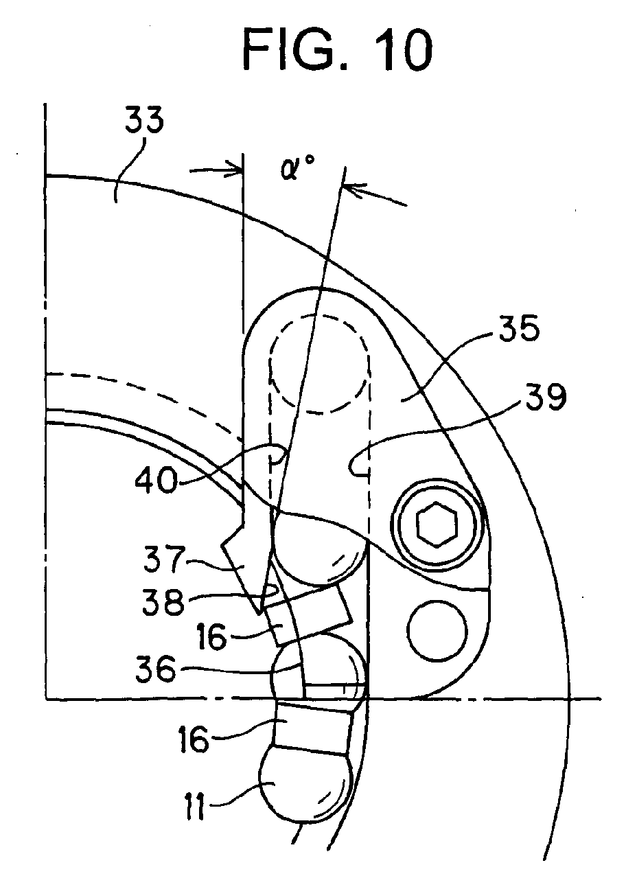
side lid 33 and thecirculation member 35. Thecirculation member 35 is mounted inside theside lid 33 and fixed to thenut body 32 by means of bolt or like. Thecirculation member 35 may have a various outer appearances in accordance with a mounting condition to theside lid 33. - With reference to FIG. 10 showing the mounting condition of the
circulation member 35, thecirculation member 35 is provided with a ball scoop-upgroove 36 which contacts and then scoops theball 11 rolling in the ball rolling passage at its both side edge portions. The ball scoop-upgroove 36 is formed, at its bottom portion, with a spacer scoop-upportion 37 for contacting and scooping thespacer 16 in the ball rolling groove without contacting theball 11. The spacer scoop-upportion 37 is formed with an escape surface 38 positioned apart from the ball rolling track and contacting thespacer 16. - The
circulation member 35 is formed with alinear passage 39, having a circular section, for moving substantially linearly theball 11 scooped by the scoop-upgroove 36. Further, in the sectional area including the center line of thelinear passage 39, the escape surface 38 of the spacer scoop-upportion 37 is inclined by a predetermined angle α with respect to the innerperipheral surface 40 of thelinear passage 39. According to this embodiment, thespacer 16 can be scooped up by the escape surface 38 even in the case where the distance between theadjacent balls spacer 16 is come off from the moving track. - FIG. 11 also represents a
ball screw 41 provided with a circulation member of deflector structure type according to another embodiment of the present invention. - With reference to this embodiment of FIG. 11, the
balls spacers ball rolling groove 41a of theball screw 41 once separated therefrom by thecirculation member 42 having deflector structure and returned, by one lead, to a portion of theball rolling groove 41a by jumping over the outer diameter portion of thescrew shaft 41. Thiscirculation member 42 is formed with a ball return groove having approximately S-shape. The ball return groove has a most recessed portion at the central portion of thecirculation member 42 so that theball 11 and thespacer 16 advancing in the ball return groove can jump over the outer peripheral portion of thescrew shaft 41. - The
circulation member 42, i.e., deflector, acts to forcibly push the ball rolling on theball rolling groove 41a from its lateral side so as to jump the ball over the outer periphery of thescrew shaft 41. Further, a spacer scoop-up portion for scooping only thespacer 16 by contacting it without contacting theball 11 is formed to thecirculation member 42. In this deflectortype circulation member 42, the escape surface formed to the scoop-up portion has a three-dimensional shape apart from the three-dimensional ball track. - The present invention further provides a linear motion guide provided with a circulation member according to the third embodiment with reference to FIG. 12.
- The linear motion guide of this embodiment is, for example, a device for guiding a movable member or body such as table on a stationary member such as bed or saddle.
- The linear motion guide comprises a
track rail 51 disposed on a stationary member and having a longitudinal extension, and a slide member assembled with thetrack rail 51 to be relatively movable. Thetrack rail 51 is formed with aball rolling groove 51a formed along the longitudinal direction thereof and the slide member is also formed with a loaded ball rolling groove so as to correspond to theball rolling groove 51a formed to trackrail 51. - The linear motion guide further comprises a number of balls disposed in a ball rolling passage formed by, in combination, the
ball rolling groove 51a of thetrack rail 51 and the loaded ball rolling groove formed to theslide member 52, a number of spacers disposed between the balls, andcirculation members slide member 52, for circulating the balls and the spacers in conformity with the relative motion of theslide member 52 with respect to thetrack rail 51. - The
track rail 51 has an elongated scale so as to provide, for example, a rectangular shape in section. Theball rolling groove 51a constitutes a track for ball rolling, and a plurality of rows ofball rolling grooves 51a may be formed in accordance with the object on use of the linear motion guide. In the illustrated embodiment, thetrack rail 51 has a linear structure, but it may have a curved rail structure. Thetrack rail 51 has screw holes to which screws are fastened so as to secure thetrack rail 51 to the stationary member. - The
slide member 52 comprises ablock body 54 and end plates as thecirculation members block body 54. Thecirculation members - The
block body 54 of theslide member 52 is a ⊐-shaped member having a flathorizontal portion 54a opposing to the upper surface of thetrack rail 51, when assembled, and a pair of support leg (skirt)portions track rail 51. Loaded ball rolling grooves are formed to the inside surfaces of theblock body 54 so as to oppose to theball rolling grooves track rail 51. Ball return passages are also formed to theblock body 54, as bores, in parallel to theball rolling grooves 51a. The ball rolling passage and the ball return passage are communicated by means of the direction changing passage formed to thecirculation member 53. A plurality of fastening holes are formed to the upper surface of theblock body 54 for fastening and securing an object to be guided to theblock body 54 by means of screws or bolts. - The
circulation member 53 will be further described hereunder with reference to FIGs. 13 and 14, in which FIG. 13 is a perspective view of a portion of thecirculation member 53 and FIG. 14 is a sectional view showing thedirection changing passage 55 formed to thecirculation member 53. - The
circulation member 53 is formed with, as shown, the ball rollingdirection changing passage 55 communicating theball return passage 56 and theball rolling passage 57. More specifically, the circulation member is formed with an outerperiphery guide portion 58 constituting the outer periphery of thedirection changing passage 55 and, on the other hand, theblock body 54 is formed with an arch-shaped innerperiphery guide portion 59 constituting the inner periphery of thedirection changing passage 55. - As shown in FIG. 13, a ball scoop-up
groove 60 is formed to the lower portion of thedirection changing passage 55 of thecirculation member 53 for contacting and then scooping the ball in theball rolling passage 57 by both side edge portions of thegroove 60. The scoop-upgroove 60 is formed on one flat surface, in parallel to thetrack rail 51, on the side of thetrack rail 51 more than thecenter line 63 of thedirection changing passage 55. The scoop-upgroove 60 has a horizontal width gradually reduced towards the ball advancing direction. The ball scooping manner of this scoop-upgroove 60 is substantially the same as that of the former embodiment. - As shown in FIGs. 13 and 14, in this embodiment, there is formed, at the bottom portion of the scoop-up
groove 60, a spacer scoop-upportion 62 for contacting and then scooping the spacer without contacting the ball in theball rolling passage 57. The spacer scoop-upportion 62 has anescape surface 61 apart from thetrack 64 of the ball scooped by the scoop-upgroove 60 but contacting the spacer. - FIG. 15 shows the track of the
ball 11 scooped by the scoop-upgroove 60. In this embodiment, different from the embodiment of the ball screw, thedirection changing passage 55 of thecirculation member 53 is bent in a circular-arc shape. Further, since the small gap exists between theball 11 and thedirection changing passage 55, thetrack 66 of the center of theball 11 passes slightly outside thecenter line 63 of the direction changing passage. Therefore, theescape surface 61 of the spacer scoop-upportion 62 is formed in consideration of this track of theball 11 so as not to contact the ball. Thisescape surface 61 may have a curved shape as shown in FIG. 15 as well as linear shape. - FIG. 16 shows the scooping state of the
ball 11 by the scoop-up groove and the scooping state of thespacer 16 by the spacer scoop-upportion 62. As shown, theball 11 is first embraced and then scooped by both the edge portions of the scoop-upgroove 60. Even if the distance between theballs 11 and thespacer 16 tends to come off from the track, the spacer scoop-upportion 62 contacting theball 11 can scoop theball 11. - An example provided with no spacer scoop-up portion is shown in FIGs. 17 and 18 for comparison.
- In this comparative example, the
ball 11 having a spherical outer surface is scooped by both the edge portions of the scoop-upgroove 60 in the embraced manner. On the other hand, thespacer 16 has a flat end shape, and in the case when the distance between theballs spacer 16 tends to come off from the track, there may cause a fear that the flat end portion of thespacer 16 adversely engages with the scoop-upgroove 60, thus being inconvenient. - FIG. 19 also shows an example of a ball spline provided with the circulation member according to the present invention.
- The ball spline is composed of a
spline shaft 71 as track rail and anouter sleeve 72 as a slide member mounted to thespline shaft 71 through a number ofballs - The
spline shaft 71 has a columnar structure having true circularity and has an outer surface formed as a ball track on which aball rolling groove 71a so as to extend its axial direction. - The
outer sleeve 72 mounted to thespline shaft 71 is formed with a loaded ball rolling groove corresponding to theball rolling groove 71a so as to constitute a ball rolling passage as a ball circulation passage in form of circuit. In this ball circulation passage, a number ofballs spacers outer sleeve 72 with respect to thespline shaft 71. That is, theball rolling passage 73 is formed by theball rolling groove 71a of thespline shaft 71 and the loaded ball rolling groove of theouter sleeve 72. Anon-loaded return passage 74, in which theballs ball rolling passage 73. On the other hand, theouter sleeve 72 is mounted with acirculation member 75 as a retainer for arranging and retaining theballs spline shaft 71. - The
circulation member 75 as a retainer is integrally mounted to theouter sleeve 72 and has an inner hollow cylindrical structure into which thespline shaft 71 is disposed in a penetrating manner. Thecirculation member 75 has an outer surface to which the circuit-formed ball circulation passage is formed. According to thiscirculation member 75, theballs ball rolling passage 73 are held from both sides between theouter sleeve 72 and thespline shaft 71 and theballs return passage 74 are held between theouter sleeve 72 and thepassage 74 to thereby prevent theballs outer sleeve 72 is withdrawn from thespline shaft 71. - A ball scoop-up groove for scooping the
balls ball rolling passage 73 is formed to thecirculation member 75, which may also be formed with a spacer scoop-up portion for scooping us thespacers 16. - It is to be noted that the present invention is not limited to the described embodiments and many other changes and modifications may be made without departing from the scopes of the appended claims.
- For example, a number of spacers arranged independently between the adjacent balls may be connected in series by using a band or belt member. Furthermore, the track rail of the motion guide device may be formed to provide a curved structure in place of the linear structure.
Claims (7)
- A circulation member (12,35,53,75) for circulating a number of balls (11) and a number of spacers (16), each spacer (16) being disposed between the balls (16), which are arranged in a ball rolling groove formed between a track member (9,34,51,71) and a movable member (10,31,52,72), in accordance with a relative motion of the movable member (10,31,52,72) with respect to the track member (9,34,51,71),
wherein the circulation member (12,35,53,75) is providedwithascoop-up groove (22,36,60) forscooping the balls (11) by contacting the ball (11) rolling in the ball rolling passage at both side edge portions of the scoop-up groove (22,36,60) and is provided with a spacer scoop-up portion (23,37,62) which contacts and scoops the spacer (16) moving in the ball rolling passage without contacting the balls (11). - The circulation member according to claim 1, wherein said spacer scoop-up portion (23,37,62) is formedwith an escape surface (24,38,61) which is apart from a track of the ball (11) scooped by the scoop-up groove (22,36,60) and contacts the spacer (16).
- A ball screw comprising:a screw shaft (9,34,41) formed, on an outer periphery thereof, with a spiral ball rolling groove;a nut (10,31) assembled with the screw shaft and formed, on an inner periphery thereof, with a spiral loaded ball rolling groove so as to oppose to the ball rolling groove formed on the screw shaft (9,34,41) to thereby form a ball rolling passage;anumberofballs (11) disposed in the ball rolling passage;a number of spacers (16) disposed between the balls (11) in the ball rolling passage; anda circulation member (12,35,42) for circulating a number of balls (11) and spacers (16), each spacer (16) being disposed between the balls (11) in accordance with a relative motion of the nut (10,31) with respect to the screw shaft (9,34,41), wherein the circulation member (12,35,42) is provided with a scoop-up groove (22,36) for scooping the balls by contacting the ball (11) rolling in the ball rolling passage at both side edge portions of the scoop-up groove (22,36) and is provided with a spacer scoop-up portion (23,37) which contacts and scoops the spacer moving in the ball rolling passage without contacting the balls.
- The ball screw according to claim 3, wherein said spacer scoop-up portion is formed with an escape surface (24,38) which is apart from a track of the ball (11) scooped by the scoop-up groove (22,36) and contacts the spacer (16).
- The ball screw according to claim 4, wherein said circulation member (12,35,42) has a linear passage (21,39) having a circular section for linearly moving theball (11) scooped up by the scoop-up groove (22,36), and said spacer scoop-up portion (23,37) is formed at a bottom portion of the scoop-up groove (22,36) and is formed with an escape surface (24,38) which is inclined by a predetermined angle with respect to an inner peripheral surface (25,40) of the linear passage (21,39) in a sectional area including a center line of the linear passage (21,39).
- A motion guide device comprising:a track rail (51,71) formed with a ball rolling groove;a slide member (52,72) mounted to the track rail (51,71) to be relatively movable with respect thereto and is formed with a loaded ball rolling groove so as to oppose to the ball rolling groove of the track rail (51,71) to thereby form a ball rolling passage;anumberofballs (11) disposed in the ball rolling passage;a number of spacers (16) disposed between the balls in the ball rolling passage; anda circulation member (53,75) for circulating a number of balls (11) and spacers (16), each spacer (16) being disposed between the balls (11) in accordance with a relative motion of the slide member (52,72) with respect to the track rail (51,71), wherein the circulation member (53,75) is provided with a scoop-up groove (60) for scooping the balls (11) by contacting the ball (11) rolling in the ball rolling passage at both side edge portions of the scoop-up groove (60) and is provided with a spacer scoop-up portion (62) which contacts and scoops the spacer (16) moving in the ball rolling passage without contacting the balls (11).
- The motion guide device according to claim 6, wherein said spacer scoop-up portion is formed with an escape surface which is apart from a track of the ball scooped by the scoop-up groove and contacts the spacer.
Applications Claiming Priority (2)
| Application Number | Priority Date | Filing Date | Title |
|---|---|---|---|
| JP2002184540A JP4053826B2 (en) | 2002-06-25 | 2002-06-25 | Circulating component, and motion guide device and ball screw using the circulating component |
| JP2002184540 | 2002-06-25 |
Publications (2)
| Publication Number | Publication Date |
|---|---|
| EP1375938A1 true EP1375938A1 (en) | 2004-01-02 |
| EP1375938B1 EP1375938B1 (en) | 2015-09-23 |
Family
ID=29717582
Family Applications (1)
| Application Number | Title | Priority Date | Filing Date |
|---|---|---|---|
| EP03014285.5A Expired - Lifetime EP1375938B1 (en) | 2002-06-25 | 2003-06-25 | Linear motion guide with a ball return passage or ball screw provided with a ball return passage |
Country Status (6)
| Country | Link |
|---|---|
| US (1) | US6874939B2 (en) |
| EP (1) | EP1375938B1 (en) |
| JP (1) | JP4053826B2 (en) |
| KR (1) | KR100953461B1 (en) |
| CN (1) | CN1320292C (en) |
| ES (1) | ES2556927T3 (en) |
Cited By (2)
| Publication number | Priority date | Publication date | Assignee | Title |
|---|---|---|---|---|
| DE102006014052B3 (en) * | 2006-03-27 | 2007-08-30 | Hiwin Technologies Corp. | Reverse channel for ball screw, has reverse bend that is formed in cross-section such that bend has large section surface so that distance piece does not contact with inner guiding surface when piece guides through bend |
| EP2023012A4 (en) * | 2006-04-28 | 2009-12-30 | Thk Co Ltd | Screw device and method of producing same |
Families Citing this family (43)
| Publication number | Priority date | Publication date | Assignee | Title |
|---|---|---|---|---|
| JP2004019905A (en) * | 2002-06-20 | 2004-01-22 | Nsk Ltd | Linear motion device |
| JP2005240878A (en) * | 2004-02-25 | 2005-09-08 | Nsk Ltd | Ball screw |
| DE102004023354A1 (en) * | 2004-05-12 | 2005-12-08 | Ina-Schaeffler Kg | Ball Screw |
| DE102004023353A1 (en) * | 2004-05-12 | 2005-12-08 | Ina-Schaeffler Kg | Ball Screw |
| DE102004037599A1 (en) * | 2004-08-03 | 2006-04-20 | Zf Lenksysteme Gmbh | Ball screw drive for an electromechanical steering system and nut for a ball screw drive |
| JP2006046530A (en) | 2004-08-05 | 2006-02-16 | Nsk Ltd | Ball screw device |
| EP1624228B1 (en) * | 2004-08-06 | 2011-10-12 | NSK Ltd. | Ball circulating member and ball screw |
| DE102004040362A1 (en) * | 2004-08-20 | 2006-02-23 | Ina-Schaeffler Kg | Ball Screw |
| CN1322255C (en) * | 2004-11-03 | 2007-06-20 | 于宙 | Axial reversing type ball screw |
| US7640820B1 (en) | 2004-11-10 | 2010-01-05 | Danaher Motion, Inc. | Ball screw assembly and spacer elements therefor |
| JPWO2006082935A1 (en) * | 2005-02-04 | 2008-06-26 | Thk株式会社 | Worm gear |
| KR100654025B1 (en) | 2005-02-24 | 2006-12-05 | 히순-첸 리 | High Speed Ballscrew Muffler |
| US7677126B2 (en) * | 2005-03-22 | 2010-03-16 | Gm Global Technology Operations, Inc. | Ball screw mechanism |
| WO2006126452A1 (en) * | 2005-05-24 | 2006-11-30 | Thk Co., Ltd. | Ball screw and movement guiding device |
| US20080190231A1 (en) * | 2005-12-01 | 2008-08-14 | Yueh Ling Chiu | Ball screw device having ball guide member |
| US20070186708A1 (en) * | 2006-02-16 | 2007-08-16 | Hiwin Technologies Corp. | Recirculating element for ball screw |
| US20080110284A1 (en) * | 2006-11-13 | 2008-05-15 | Hung-Sung Pan | Sectional Circulating Assembly for a Ball Screw |
| US7516681B2 (en) * | 2007-07-13 | 2009-04-14 | Hiwin Technologies Corp. | External circulation type ball screw |
| CN101382188B (en) * | 2007-09-03 | 2010-07-28 | 上银科技股份有限公司 | External circulation type ball screw |
| US8336415B2 (en) * | 2007-11-02 | 2012-12-25 | Thk Co., Ltd. | Roller screw |
| TWI338094B (en) * | 2008-08-29 | 2011-03-01 | Hiwin Tech Corp | Ball screw module and circulating device therein |
| US8955404B2 (en) | 2008-08-29 | 2015-02-17 | Hiwin Technologies Corp | Ball screw module |
| US20120174693A1 (en) * | 2008-09-25 | 2012-07-12 | Hsieh Wu Teng | Ball bearing device for motion guide device |
| DE102008058399B4 (en) | 2008-11-21 | 2012-05-03 | Hiwin Technologies Corp. | Ball bearing assembly for a motion guide |
| JP4633846B2 (en) * | 2009-03-31 | 2011-02-16 | Thk株式会社 | Ball screw spline |
| US20100307272A1 (en) * | 2009-06-09 | 2010-12-09 | Hiwin Technologies Corp. | Deflecting device for motion guide apparatus |
| US9062748B1 (en) * | 2009-09-30 | 2015-06-23 | David B. Guglietti | Ball screw nut |
| US9279487B1 (en) | 2009-09-30 | 2016-03-08 | David B. Guglietti | Ball screw and parts |
| CN102171490A (en) * | 2009-12-25 | 2011-08-31 | 日本精工株式会社 | Ball screw |
| US9003911B2 (en) * | 2010-12-08 | 2015-04-14 | Nsk Ltd. | Ball screw device |
| WO2012081143A1 (en) * | 2010-12-14 | 2012-06-21 | 日本精工株式会社 | Ball screw device |
| CN103122980B (en) * | 2011-11-18 | 2016-01-06 | 上银科技股份有限公司 | The assembling method of the rolling module of linear actuator and linear actuator |
| JP6151161B2 (en) * | 2013-11-29 | 2017-06-21 | 株式会社ショーワ | Ball screw and power steering device |
| JP5932926B2 (en) * | 2014-09-19 | 2016-06-08 | Thk株式会社 | Motion guide device, actuator |
| CN107208763B (en) * | 2015-01-28 | 2018-08-28 | Thk株式会社 | Screw device |
| US9955802B2 (en) | 2015-04-08 | 2018-05-01 | Fasteners For Retail, Inc. | Divider with selectively securable track assembly |
| JP6668652B2 (en) * | 2015-09-18 | 2020-03-18 | 日本精工株式会社 | Linear motion guide device, end cap for linear motion guide device |
| DE102016007542A1 (en) * | 2016-06-22 | 2017-12-28 | Thyssenkrupp Ag | Ball screw drive of an electromechanical power steering with deflecting body for a ball return |
| KR20190136312A (en) | 2018-05-30 | 2019-12-10 | 셰플러코리아(유) | A Ball Screw Having Recirculation Guide |
| US10767741B1 (en) | 2019-03-12 | 2020-09-08 | Hiwin Technologies Corp. | Linear transmission device |
| KR102182349B1 (en) * | 2019-03-25 | 2020-11-25 | 하이윈 테크놀로지스 코포레이션 | Linear transmission device |
| RU194826U1 (en) * | 2019-10-16 | 2019-12-24 | Акционерное общество "Концерн "Калашников" | Ball screw |
| CN112682425B (en) * | 2020-12-03 | 2022-05-20 | 宁波美亚特精密传动部件有限公司 | Linear bearing capable of automatically feeding oil during working |
Citations (9)
| Publication number | Priority date | Publication date | Assignee | Title |
|---|---|---|---|---|
| US4749284A (en) * | 1985-05-28 | 1988-06-07 | Hiroshi Teramachi | Linear sliding ball bearing |
| SU1441121A1 (en) * | 1987-05-27 | 1988-11-30 | Хабаровский политехнический институт | Ball-screw mechanism |
| JPH07208466A (en) * | 1994-01-24 | 1995-08-11 | Thk Kk | Linear guide device |
| EP0857883A1 (en) * | 1996-09-17 | 1998-08-12 | Thk Co. Ltd. | Ball connecting body, and linear guide device and ball screw device utilizing the ball connecting body |
| EP0967414A2 (en) * | 1998-06-26 | 1999-12-29 | Thk Co. Ltd. | Ball screw |
| US6102572A (en) * | 1998-03-04 | 2000-08-15 | Nippoon Thompson Co., Ltd. | Linear motion guide units |
| US6176149B1 (en) * | 1999-05-28 | 2001-01-23 | Tsubaki Nakashima Co., Ltd. | Ball screw having spacers |
| US20020026844A1 (en) * | 2000-07-18 | 2002-03-07 | Satoshi Fujita | Ball screw |
| EP1318332A2 (en) * | 2001-12-05 | 2003-06-11 | Thk Co., Ltd. | Circulation member for ball screw device |
Family Cites Families (12)
| Publication number | Priority date | Publication date | Assignee | Title |
|---|---|---|---|---|
| SE508411C2 (en) * | 1997-04-29 | 1998-10-05 | Ovako Steel Ab | Micro-alloy steel for rolling bearings and hub bearing unit made of steel |
| KR100373570B1 (en) | 1997-07-31 | 2003-02-26 | 티에치케이 가부시끼가이샤 | Ball screw device |
| US6248186B1 (en) * | 1997-11-07 | 2001-06-19 | Nsk Ltd. | Ball-and-roller bearing and method of manufacturing the same |
| US6267511B1 (en) * | 1998-03-05 | 2001-07-31 | Nsk Ltd. | Rolling bearing |
| JP2000282178A (en) * | 1998-10-22 | 2000-10-10 | Nsk Ltd | Rolling bearing |
| US6357924B1 (en) * | 1998-12-21 | 2002-03-19 | Nsk Ltd. | Rolling bearing |
| JP4256003B2 (en) * | 1999-01-29 | 2009-04-22 | Thk株式会社 | Rolling element holding spacer and linear motion apparatus using the same |
| JP4441947B2 (en) * | 1999-05-20 | 2010-03-31 | 日本精工株式会社 | Rolling bearing |
| JP2000337470A (en) * | 1999-05-28 | 2000-12-05 | Tsubaki Nakashima Co Ltd | Ball screw |
| JP4503866B2 (en) | 2000-03-13 | 2010-07-14 | Thk株式会社 | Rolling guide device and driving device using the rolling guide device |
| JP2002031207A (en) | 2000-07-13 | 2002-01-31 | Nsk Ltd | Circulating tube ball screw |
| JP4834921B2 (en) * | 2001-01-30 | 2011-12-14 | 日本精工株式会社 | Rotation support device for pulley for compressor |
-
2002
- 2002-06-25 JP JP2002184540A patent/JP4053826B2/en not_active Expired - Lifetime
-
2003
- 2003-06-23 US US10/600,453 patent/US6874939B2/en not_active Expired - Lifetime
- 2003-06-24 KR KR1020030040962A patent/KR100953461B1/en not_active Expired - Lifetime
- 2003-06-25 CN CNB031438903A patent/CN1320292C/en not_active Expired - Lifetime
- 2003-06-25 EP EP03014285.5A patent/EP1375938B1/en not_active Expired - Lifetime
- 2003-06-25 ES ES03014285.5T patent/ES2556927T3/en not_active Expired - Lifetime
Patent Citations (9)
| Publication number | Priority date | Publication date | Assignee | Title |
|---|---|---|---|---|
| US4749284A (en) * | 1985-05-28 | 1988-06-07 | Hiroshi Teramachi | Linear sliding ball bearing |
| SU1441121A1 (en) * | 1987-05-27 | 1988-11-30 | Хабаровский политехнический институт | Ball-screw mechanism |
| JPH07208466A (en) * | 1994-01-24 | 1995-08-11 | Thk Kk | Linear guide device |
| EP0857883A1 (en) * | 1996-09-17 | 1998-08-12 | Thk Co. Ltd. | Ball connecting body, and linear guide device and ball screw device utilizing the ball connecting body |
| US6102572A (en) * | 1998-03-04 | 2000-08-15 | Nippoon Thompson Co., Ltd. | Linear motion guide units |
| EP0967414A2 (en) * | 1998-06-26 | 1999-12-29 | Thk Co. Ltd. | Ball screw |
| US6176149B1 (en) * | 1999-05-28 | 2001-01-23 | Tsubaki Nakashima Co., Ltd. | Ball screw having spacers |
| US20020026844A1 (en) * | 2000-07-18 | 2002-03-07 | Satoshi Fujita | Ball screw |
| EP1318332A2 (en) * | 2001-12-05 | 2003-06-11 | Thk Co., Ltd. | Circulation member for ball screw device |
Non-Patent Citations (1)
| Title |
|---|
| PATENT ABSTRACTS OF JAPAN vol. 1995, no. 11 26 December 1995 (1995-12-26) * |
Cited By (3)
| Publication number | Priority date | Publication date | Assignee | Title |
|---|---|---|---|---|
| DE102006014052B3 (en) * | 2006-03-27 | 2007-08-30 | Hiwin Technologies Corp. | Reverse channel for ball screw, has reverse bend that is formed in cross-section such that bend has large section surface so that distance piece does not contact with inner guiding surface when piece guides through bend |
| EP2023012A4 (en) * | 2006-04-28 | 2009-12-30 | Thk Co Ltd | Screw device and method of producing same |
| US8132479B2 (en) | 2006-04-28 | 2012-03-13 | Thk Co., Ltd. | Screw device and method of manufacturing the same |
Also Published As
| Publication number | Publication date |
|---|---|
| US20040000208A1 (en) | 2004-01-01 |
| JP4053826B2 (en) | 2008-02-27 |
| ES2556927T3 (en) | 2016-01-21 |
| CN1480665A (en) | 2004-03-10 |
| US6874939B2 (en) | 2005-04-05 |
| KR20040002653A (en) | 2004-01-07 |
| KR100953461B1 (en) | 2010-04-16 |
| JP2004028192A (en) | 2004-01-29 |
| CN1320292C (en) | 2007-06-06 |
| EP1375938B1 (en) | 2015-09-23 |
Similar Documents
| Publication | Publication Date | Title |
|---|---|---|
| EP1375938B1 (en) | Linear motion guide with a ball return passage or ball screw provided with a ball return passage | |
| EP1486690B1 (en) | Spacer for linear motion apparatus and linear motion apparatus provided with spacer | |
| JP3950511B2 (en) | Linear motion rolling guide unit | |
| EP0930450B1 (en) | Ball screw unit | |
| US6247846B1 (en) | Rolling element and rectilinearly-movable apparatus using the rolling element | |
| US7798718B2 (en) | Rolling element accommodating belt for linear guide apparatus and linear guide apparatus | |
| EP0846880B1 (en) | Slide guide and its roller chain with ends | |
| JPS6343607B2 (en) | ||
| EP2068016A1 (en) | Linear guidance device | |
| US7121723B2 (en) | Linear guide apparatus | |
| US7329047B2 (en) | Rolling member connection belt and motion guide device provided with same | |
| CN114483783A (en) | Linear motion guide unit | |
| US20030179962A1 (en) | Linear motion guide unit with separator between any two adjoining rollers | |
| JP2004068880A (en) | Linear motion device | |
| JP4340547B2 (en) | Guide unit with built-in roller chain | |
| US5207510A (en) | Linear ball bearing assembly | |
| JP4142771B2 (en) | Ball bearing for linear motion | |
| EP1319853A2 (en) | Linear-Motion device and method of manufacturing the same | |
| US5649769A (en) | Linear motion rolling guide unit | |
| EP1953399A1 (en) | Movement guiding device | |
| KR100644972B1 (en) | Guide belt | |
| JPS6159402B2 (en) | ||
| JP2008249043A (en) | Rolling element housing belt and linear motion guide device | |
| JP2007132429A (en) | Linear guide device | |
| JP2005180580A (en) | Linear motion guide bearing device |
Legal Events
| Date | Code | Title | Description |
|---|---|---|---|
| PUAI | Public reference made under article 153(3) epc to a published international application that has entered the european phase |
Free format text: ORIGINAL CODE: 0009012 |
|
| AK | Designated contracting states |
Kind code of ref document: A1 Designated state(s): AT BE BG CH CY CZ DE DK EE ES FI FR GB GR HU IE IT LI LU MC NL PT RO SE SI SK TR |
|
| AX | Request for extension of the european patent |
Extension state: AL LT LV MK |
|
| 17P | Request for examination filed |
Effective date: 20040122 |
|
| AKX | Designation fees paid |
Designated state(s): AT BE BG CH CY CZ DE DK EE ES FI FR GB GR HU IE IT LI LU MC NL PT RO SE SI SK TR |
|
| 17Q | First examination report despatched |
Effective date: 20080311 |
|
| REG | Reference to a national code |
Ref country code: DE Ref legal event code: R079 Ref document number: 60348075 Country of ref document: DE Free format text: PREVIOUS MAIN CLASS: F16C0019200000 Ipc: F16H0025220000 |
|
| GRAP | Despatch of communication of intention to grant a patent |
Free format text: ORIGINAL CODE: EPIDOSNIGR1 |
|
| RIC1 | Information provided on ipc code assigned before grant |
Ipc: F16H 25/22 20060101AFI20150330BHEP Ipc: F16C 29/06 20060101ALI20150330BHEP Ipc: F16C 33/37 20060101ALI20150330BHEP |
|
| INTG | Intention to grant announced |
Effective date: 20150417 |
|
| GRAS | Grant fee paid |
Free format text: ORIGINAL CODE: EPIDOSNIGR3 |
|
| GRAA | (expected) grant |
Free format text: ORIGINAL CODE: 0009210 |
|
| AK | Designated contracting states |
Kind code of ref document: B1 Designated state(s): AT BE BG CH CY CZ DE DK EE ES FI FR GB GR HU IE IT LI LU MC NL PT RO SE SI SK TR |
|
| REG | Reference to a national code |
Ref country code: GB Ref legal event code: FG4D |
|
| REG | Reference to a national code |
Ref country code: CH Ref legal event code: EP |
|
| REG | Reference to a national code |
Ref country code: AT Ref legal event code: REF Ref document number: 751437 Country of ref document: AT Kind code of ref document: T Effective date: 20151015 |
|
| REG | Reference to a national code |
Ref country code: IE Ref legal event code: FG4D |
|
| REG | Reference to a national code |
Ref country code: DE Ref legal event code: R096 Ref document number: 60348075 Country of ref document: DE |
|
| REG | Reference to a national code |
Ref country code: ES Ref legal event code: FG2A Ref document number: 2556927 Country of ref document: ES Kind code of ref document: T3 Effective date: 20160121 |
|
| REG | Reference to a national code |
Ref country code: NL Ref legal event code: MP Effective date: 20150923 |
|
| PG25 | Lapsed in a contracting state [announced via postgrant information from national office to epo] |
Ref country code: FI Free format text: LAPSE BECAUSE OF FAILURE TO SUBMIT A TRANSLATION OF THE DESCRIPTION OR TO PAY THE FEE WITHIN THE PRESCRIBED TIME-LIMIT Effective date: 20150923 Ref country code: GR Free format text: LAPSE BECAUSE OF FAILURE TO SUBMIT A TRANSLATION OF THE DESCRIPTION OR TO PAY THE FEE WITHIN THE PRESCRIBED TIME-LIMIT Effective date: 20151224 |
|
| REG | Reference to a national code |
Ref country code: AT Ref legal event code: MK05 Ref document number: 751437 Country of ref document: AT Kind code of ref document: T Effective date: 20150923 |
|
| PG25 | Lapsed in a contracting state [announced via postgrant information from national office to epo] |
Ref country code: SE Free format text: LAPSE BECAUSE OF FAILURE TO SUBMIT A TRANSLATION OF THE DESCRIPTION OR TO PAY THE FEE WITHIN THE PRESCRIBED TIME-LIMIT Effective date: 20150923 |
|
| PG25 | Lapsed in a contracting state [announced via postgrant information from national office to epo] |
Ref country code: NL Free format text: LAPSE BECAUSE OF FAILURE TO SUBMIT A TRANSLATION OF THE DESCRIPTION OR TO PAY THE FEE WITHIN THE PRESCRIBED TIME-LIMIT Effective date: 20150923 |
|
| PG25 | Lapsed in a contracting state [announced via postgrant information from national office to epo] |
Ref country code: CZ Free format text: LAPSE BECAUSE OF FAILURE TO SUBMIT A TRANSLATION OF THE DESCRIPTION OR TO PAY THE FEE WITHIN THE PRESCRIBED TIME-LIMIT Effective date: 20150923 Ref country code: EE Free format text: LAPSE BECAUSE OF FAILURE TO SUBMIT A TRANSLATION OF THE DESCRIPTION OR TO PAY THE FEE WITHIN THE PRESCRIBED TIME-LIMIT Effective date: 20150923 Ref country code: SK Free format text: LAPSE BECAUSE OF FAILURE TO SUBMIT A TRANSLATION OF THE DESCRIPTION OR TO PAY THE FEE WITHIN THE PRESCRIBED TIME-LIMIT Effective date: 20150923 |
|
| PG25 | Lapsed in a contracting state [announced via postgrant information from national office to epo] |
Ref country code: AT Free format text: LAPSE BECAUSE OF FAILURE TO SUBMIT A TRANSLATION OF THE DESCRIPTION OR TO PAY THE FEE WITHIN THE PRESCRIBED TIME-LIMIT Effective date: 20150923 Ref country code: PT Free format text: LAPSE BECAUSE OF FAILURE TO SUBMIT A TRANSLATION OF THE DESCRIPTION OR TO PAY THE FEE WITHIN THE PRESCRIBED TIME-LIMIT Effective date: 20160125 Ref country code: RO Free format text: LAPSE BECAUSE OF FAILURE TO SUBMIT A TRANSLATION OF THE DESCRIPTION OR TO PAY THE FEE WITHIN THE PRESCRIBED TIME-LIMIT Effective date: 20150923 |
|
| REG | Reference to a national code |
Ref country code: DE Ref legal event code: R097 Ref document number: 60348075 Country of ref document: DE |
|
| PLBE | No opposition filed within time limit |
Free format text: ORIGINAL CODE: 0009261 |
|
| STAA | Information on the status of an ep patent application or granted ep patent |
Free format text: STATUS: NO OPPOSITION FILED WITHIN TIME LIMIT |
|
| 26N | No opposition filed |
Effective date: 20160624 |
|
| PG25 | Lapsed in a contracting state [announced via postgrant information from national office to epo] |
Ref country code: DK Free format text: LAPSE BECAUSE OF FAILURE TO SUBMIT A TRANSLATION OF THE DESCRIPTION OR TO PAY THE FEE WITHIN THE PRESCRIBED TIME-LIMIT Effective date: 20150923 |
|
| PG25 | Lapsed in a contracting state [announced via postgrant information from national office to epo] |
Ref country code: SI Free format text: LAPSE BECAUSE OF FAILURE TO SUBMIT A TRANSLATION OF THE DESCRIPTION OR TO PAY THE FEE WITHIN THE PRESCRIBED TIME-LIMIT Effective date: 20150923 |
|
| PG25 | Lapsed in a contracting state [announced via postgrant information from national office to epo] |
Ref country code: BE Free format text: LAPSE BECAUSE OF FAILURE TO SUBMIT A TRANSLATION OF THE DESCRIPTION OR TO PAY THE FEE WITHIN THE PRESCRIBED TIME-LIMIT Effective date: 20150923 |
|
| PG25 | Lapsed in a contracting state [announced via postgrant information from national office to epo] |
Ref country code: MC Free format text: LAPSE BECAUSE OF FAILURE TO SUBMIT A TRANSLATION OF THE DESCRIPTION OR TO PAY THE FEE WITHIN THE PRESCRIBED TIME-LIMIT Effective date: 20150923 |
|
| REG | Reference to a national code |
Ref country code: CH Ref legal event code: PL |
|
| GBPC | Gb: european patent ceased through non-payment of renewal fee |
Effective date: 20160625 |
|
| REG | Reference to a national code |
Ref country code: IE Ref legal event code: MM4A |
|
| REG | Reference to a national code |
Ref country code: FR Ref legal event code: ST Effective date: 20170228 |
|
| PG25 | Lapsed in a contracting state [announced via postgrant information from national office to epo] |
Ref country code: LI Free format text: LAPSE BECAUSE OF NON-PAYMENT OF DUE FEES Effective date: 20160630 Ref country code: CH Free format text: LAPSE BECAUSE OF NON-PAYMENT OF DUE FEES Effective date: 20160630 Ref country code: FR Free format text: LAPSE BECAUSE OF NON-PAYMENT OF DUE FEES Effective date: 20160630 |
|
| PG25 | Lapsed in a contracting state [announced via postgrant information from national office to epo] |
Ref country code: IE Free format text: LAPSE BECAUSE OF NON-PAYMENT OF DUE FEES Effective date: 20160625 Ref country code: GB Free format text: LAPSE BECAUSE OF NON-PAYMENT OF DUE FEES Effective date: 20160625 |
|
| PG25 | Lapsed in a contracting state [announced via postgrant information from national office to epo] |
Ref country code: CY Free format text: LAPSE BECAUSE OF FAILURE TO SUBMIT A TRANSLATION OF THE DESCRIPTION OR TO PAY THE FEE WITHIN THE PRESCRIBED TIME-LIMIT Effective date: 20150923 Ref country code: HU Free format text: LAPSE BECAUSE OF FAILURE TO SUBMIT A TRANSLATION OF THE DESCRIPTION OR TO PAY THE FEE WITHIN THE PRESCRIBED TIME-LIMIT; INVALID AB INITIO Effective date: 20030625 |
|
| PG25 | Lapsed in a contracting state [announced via postgrant information from national office to epo] |
Ref country code: LU Free format text: LAPSE BECAUSE OF NON-PAYMENT OF DUE FEES Effective date: 20160625 Ref country code: TR Free format text: LAPSE BECAUSE OF FAILURE TO SUBMIT A TRANSLATION OF THE DESCRIPTION OR TO PAY THE FEE WITHIN THE PRESCRIBED TIME-LIMIT Effective date: 20150923 |
|
| PG25 | Lapsed in a contracting state [announced via postgrant information from national office to epo] |
Ref country code: BG Free format text: LAPSE BECAUSE OF FAILURE TO SUBMIT A TRANSLATION OF THE DESCRIPTION OR TO PAY THE FEE WITHIN THE PRESCRIBED TIME-LIMIT Effective date: 20150923 |
|
| PGFP | Annual fee paid to national office [announced via postgrant information from national office to epo] |
Ref country code: IT Payment date: 20220627 Year of fee payment: 20 Ref country code: DE Payment date: 20220620 Year of fee payment: 20 |
|
| PGFP | Annual fee paid to national office [announced via postgrant information from national office to epo] |
Ref country code: ES Payment date: 20220829 Year of fee payment: 20 |
|
| REG | Reference to a national code |
Ref country code: DE Ref legal event code: R071 Ref document number: 60348075 Country of ref document: DE |
|
| REG | Reference to a national code |
Ref country code: ES Ref legal event code: FD2A Effective date: 20230630 |
|
| PG25 | Lapsed in a contracting state [announced via postgrant information from national office to epo] |
Ref country code: ES Free format text: LAPSE BECAUSE OF EXPIRATION OF PROTECTION Effective date: 20230626 |