BACKGROUND OF THE INVENTION
1. Field of the invention
This invention relates to a sewing machine including a cassette mount
to which a thread cassette is attached and a thread tension control program
therefor, and more particularly to a technique for reliably and desirably
adjusting the tension of a thread drawn from the thread cassette when the
thread cassette is attached to and detached from the cassette mount.
2. Description of the related art
Sewing machines have commercially been provided including a
cassette mount to which a thread cassette enclosing a thread spool or bobbin
is detachably attached in order that a thread drawn from the thread spool
may be used as an upper thread. The thread drawn from the thread
cassette attached to the cassette mount is placed between a pair of thread
tension discs. The thread extending from the thread tension discs is
further placed on a thread take-up. The thread extending from the thread
take-up is passed through an eye of a sewing needle so that the thread is
set.
In one type of the above-described sewing machines, the thread
drawn from the thread cassette is automatically placed between the thread
tension discs. However, in order that sewing may be started, the thread
tension discs need to be closed so that the thread is held therebetween.
Furthermore, in order that the thread cassette may be detached from the
cassette mount, the thread tension discs need to be opened so that the
thread is released from the held state.
In view of the aforesaid requirement, the assignee of the present
application filed a patent application for a sewing machine including a thread
tension disc operating mechanism operated mechanically in synchronization
with attachment of the thread cassette. This Japanese patent application
was published on July 10, 2002 under the publication number JP-A-2002-191884.
In the disclosed sewing machine, a pair of thread tension
discs are held in a closed state when a thread cassette is absent in a cassette
mount. When the thread cassette is inserted into the cassette mount, the
thread tension disc operating mechanism is firstly operated to open the
thread tension discs.
The thread drawn from the thread cassette is subsequently placed
between the thread tension discs, and simultaneously, the discs are closed
such that the thread is held between the discs. Furthermore, when the
thread cassette is detached from the cassette mount, the above-described
operation is performed in a reverse sequence by the thread tension disc
operating mechanism so that the thread is released from the thread tension
discs.
U.S. Patent No. 3,749,039 to Russell A. Fritts discloses a sewing
machine including a rotatable guide member provided at the thread tension
disc side. The guide member corresponds to a part of the aforesaid thread
tension disc operating mechanism and is rotated by attaching and detaching
the thread cassette to and from the cassette mount, whereby the thread
tension discs are opened and closed. Furthermore, the prior art has
provided a technique for opening a pair of thread tension discs by raising a
presser foot pressing cloth. Additionally, a lever may be provided which is
operated to detach the thread cassette from the thread attaching portion.
In the aforesaid sewing machine disclosed in JP-A-2002-191884,
however, the thread tension disc operating mechanism and the thread
tension discs are operated in response to attachment or detachment of the
thread cassette to or from the cassette mount. The force operating the
thread tension disc operating mechanism and the thread tension discs needs
to be exerted by an operator. Since this increases load of the operator, the
thread cassette cannot be attached to and detached from the cassette mount
smoothly. Furthermore, the thread tension discs closed need to be opened
and thereafter re-closed when the thread cassette is attached to the
cassette mount. However, it is difficult to obtain proper timings for the
opening and closure of the thread tension discs. Accordingly, the thread
extending from the thread cassette cannot sometimes be caught by the
thread tension discs reliably. The thread cassette needs to be re-attached
to the cassette mount when the thread has not been caught by the thread
tension discs. This would result in troublesomeness.
SUMMARY OF THE INVENTION
Therefore, an object of the present invention is to provide a sewing
machine in which the load imposed on the operator can be reduced with
improved smoothness in the attachment and detachment of the thread
cassette when the thread cassette is attached to and detached from the
cassette mount, and the tension of the thread drawn from the thread
cassette can be adjusted reliably and desirably, and to provide a thread
tension control program which can be applied to the sewing machine.
The present invention provides a sewing machine comprising a thread
cassette having a thread accommodating cavity in which a supply of thread
is accommodated, a cassette mount to which the thread cassette is
detachably attached, a thread tensioner adjusting a tension of the thread
drawn from the thread cassette, a detachment operating member operated
so that the thread cassette is detached from the cassette mount, and a thread
tension control controlling the thread tensioner so that the thread is set at a
predetermined tension when the detachment operating member has been
operated.
The tension of thread drawn from the thread cassette is adjusted by
the thread tensioner in the above-described sewing machine. The
detachment operating member is operated so that the thread cassette is
allowed to be detached from the cassette mount. Upon operation of the
detachment operating member, the thread tension control controls the
thread tensioner so that the predetermined tension is applied to the thread.
Accordingly, the load imposed on the operator can be reduced with
improvement of the smoothness in the attachment and detachment of the
thread cassette when the operator detaches the thread cassette from the
cassette mount. Consequently, the tension of the thread drawn from the
thread cassette can be adjusted reliably and desirably.
In a preferred form, the thread tension control opens the thread
tensioner when the detachment operating member has been operated. In
another preferred form, the thread tensioner applies no tension to the thread
when the thread tensioner is opened. Furthermore, the sewing machine
preferably further comprises a thread tensioner opening mechanism
operated in synchronization with the detachment operating member and
opening the thread tensioner when the detachment operating member is
operated.
The invention also provides a sewing machine comprising a thread
cassette having a thread accommodating cavity in which a supply of thread
is stored, a cassette mount to which the thread cassette is detachably
attached, a thread tensioner adjusting a tension of the thread drawn from the
thread cassette, a cassette detector detecting the thread cassette having
been attached to the cassette mount, and a thread tension control controlling
the thread tensioner so that the thread is tensioned a predetermined period
of time after detection of the thread cassette by the cassette detector.
The tension of thread drawn from the thread cassette is adjusted by
the thread tensioner also in the above-described sewing machine. When
having been attached to the cassette mount, the thread cassette is detected
by the cassette detector. The thread tensioner is controlled by the thread
tension control the predetermined period of time after detection of the
thread cassette by the cassette detector, whereupon the thread drawn from
the thread cassette is tensioned. Thus, since the thread drawn from the
thread cassette is tensioned the predetermined period of time after
detection of the thread cassette by the cassette detector. Consequently,
the thread can reliably be caught and held by the thread tensioner.
The aforesaid predetermined period of time is preferably set at a
value not more than 30 msec.
BRIEF DESCRIPTION OF THE DRAWINGS
Other objects, features and advantages of the present invention will
become clear upon reviewing the following description of an embodiment of
the invention, made with reference to the accompanying drawings, in which:
DETAILED DESCRIPTION OF THE INVENTION
One embodiment of the present invention will be described with
reference to the accompanying drawings. In the embodiment, the present
invention is applied to a household sewing machine provided with a cassette
mount to which a thread cassette having a thread accommodating cavity in
which a supply of thread is accommodated is detachably attached.
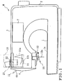
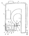
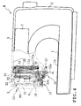
Referring to FIGS. 1 to 4, the household sewing machine M includes a
sewing bed 1 having a horizontal plane, a pillar 2 standing from a right end of
the bed 1, a sewing arm 3 extending leftward from an upper end of the pillar
2 so as to be opposed along the bed 1, and a machine head 4 located at a left
end of the arm 3. The head 4 is provided with a cassette mount 5 to which
a thread cassette 10 is detachably attached. A thread 11 drawn from the
thread cassette 10 attached to the cassette mount 5 serves as a needle
thread. The arm 3 or the head 4 thereof includes operation switches 6 (see
FIG. 14) such as a sewing start switch, a sewing finish switch, etc. The arm
3 further includes a liquid crystal display 7. A touch panel 8 (see FIG. 14) is
provided on the surface of the display 7.
In the head 4 are provided a needle bar 12, a needle thread take-up 13,
a thread tensioning mechanism 14 for adjusting a tension of the thread 11
drawn from the thread cassette 10, and a thread tension releasing.
mechanism 15 rendering the thread tensioning mechanism 14 open when a
detachment operating member has been operated, as shown in FIGS. 2, 4, 9
and 10. The head 4 also includes a threading mechanism 16 for
automatically passing a thread 11 through an eye of a sewing needle 12a
attached to the needle bar 12 when the thread cassette 10 is attached to the
cassette mount 5, a thread guiding mechanism 17 for automatically catching
the thread 11 on a thread guard of the needle bar 12 and the like when the
thread cassette 10 is attached to the cassette mount 5, a needle bar driving
mechanism 18 for moving the needle bar 12 up and down, a needle bar
swinging mechanism 19 for swinging the needle bar 12, a needle thread
take-up driving mechanism, etc.
The thread 11 drawn from the thread cassette 10 attached to the
cassette mount 5 is put on a thread tensioning shaft 40 (see FIG. 11 etc.)
between thread tension discs 41 and 42 of the thread tensioning mechanism
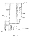
14 from above, as shown in FIGS. 5 and 6. The thread 11 further extending
from the thread tensioning shaft 40 downstream is put on the needle thread
take-up 13. The thread 11 further extending from the needle thread
take-up 13 downstream is passed through an eye of the needle 12a attached
to the needle bar 12, whereupon the thread 11 is set for the sewing.
The bed 1 is provided with a bobbin mount (not shown). A thread
extending from a bobbin (not shown) attached to the bobbin mount serves as
a bobbin thread. A shuttle mechanism (not shown) is provided in the bed 1.
When a sewing machine motor 9 (see FIG. 14) is driven with the needle and
bobbin threads being set, the needle bar 12 is moved up and down by the
needle bar driving mechanism 18 and the shuttle mechanism is driven in
synchronization with the movement of the needle bar 12, so that the needle
thread 11 located near the needle 12a descended below a throat plate 1a is
caught by the shuttle mechanism, whereupon the needle and bobbin threads
are entangled to be formed into stitches.
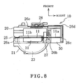
The thread cassette 10 will now be described in detail. The thread
cassette 10 includes a cassette body 20 and a lid 21 pivotally mounted on the
cassette body as shown in FIGS. 5 to 8. The cassette body 20 with the lid
21 defines therein a thread accommodating cavity 23 for accommodating a
thread spool 22 serving as a supply of thread. A spool pin 24 is mounted on
the lid 21. When the lid 21 is opened forward as shown in FIG. 7, the thread
spool 22 is allowed to be attached to and detached from the spool pin 24.
When the lid 21 is closed with the thread spool 22 attached to the spool pin
24, the thread spool is enclosed in the thread accommodating cavity 23.
The thread 11 extends upward from the thread spool 22 to be drawn
out of the thread accommodating cavity 23. The thread 11 further extends
through a thread path 25 defined between the cassette body 20 and a
left-hand end of the lid 21. The thread 11 is then put on a first thread guard
26a at a left lower end of the thread cassette 10, further extending rightward
thereafter to be put on a second thread guard 26b at a lower end of a
partition wall 27 and a third thread guard 26c at a right lower end of the
thread cassette 10. The thread 11 further extends forward to be put on a
fourth thread guard 26d and is then returned to extend leftward. The
thread 11 is then retained on a thread retainer 28. Furthermore, the thread
11 extending leftward is cut by a left blade 29 of the thread retainer 28 and
the resultant thread end is put on a fifth thread guard 26e near the blade 29.
The thread 11 is thus set in the thread cassette 10 as described above
prior to attachment to the cassette mount 5. A needle thread take-up guide
space 30 defined at a right end of the thread cassette 10 extends
substantially over the length of the cassette. The guide space 30 is open at
the rear and the lower portion of the cassette. A thread tension space 31 is
defined at a central lower end of the thread cassette 10 and open at a lower
portion thereof. These spaces 30 and 31 are partitioned by a partition wall
27.
The thread cassette 10 is descended to be inserted into the cassette
mount 5. In this case, the needle thread take-up 13 and a needle thread
take-up guide 13a (see FIG. 2) guiding the former enter the guide space 30
from below the cassette, and the thread tensioning shaft 40 and thread
tension discs 41 and 42 of the thread tensioning mechanism 14 enter the
thread tension space 31 from below the cassette. The cassette body 20 has
a notch 20a formed in a lower end of the rear wall thereof in order that the
thread tensioning shaft 40 and the like may be prevented from interfering
with the thread cassette 10. When the thread cassette 10 has been inserted
slightly into the cassette mount 5, a thread part 11a between the thread
guards 26b and 26c is caught by the needle thread take-up 13 in the guide
space 30.
Subsequently, when the thread cassette 10 is further inserted into the
cassette mount 5, the thread guards 26a and 26b are descended relative to
the needle thread take-up 13 on which the thread part 11a has been caught.
Since the thread 11 located downstream the caught thread part 11a is
continuously held by the thread retainer 28, the thread 11 is drawn from the
thread spool 22 in the thread accommodating cavity 23. For example, the
thread part 11a takes a generally triangular configuration when about two
thirds of the thread cassette 10 has been inserted into the cassette mount 5
as shown in FIGS. 1 and 2. When the thread cassette 10 has been attached
to the cassette mount 5, the thread part 11a between the thread guards 26a
and 26b is caught by a portion of the thread tensioning shaft 40 between the
thread tension discs 41 and 42 in the thread tension space 31, as shown in
FIGS. 3 and 4.
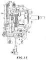
The thread tensioning mechanism 14 will now be described. The
thread tensioning mechanism 14 comprises the thread tensioning shaft 40
fixed to a frame 40a and extending forward, the front thread tension disc 41
fixedly fitted with the shaft 40, and the rear thread tension disc 42 fitted with
the shaft 40 so as to be brought into a face-to-face contact with the front
disc 41, as shown in FIGS. 9 to 13B. The thread tensioning mechanism 14
further comprises a thread tension spring 42a provided about the shaft 40 to
urge the rear disc 42 against the front disc 41 and a driving mechanism 43
opening and closing the paired thread tension discs 41 and 42. The driving
mechanism 43 includes a pulse motor 44, a driving gear 45, a cam 46, links
47 and 48, a rotating link 49, an extension coil spring 50, a pushing link 51,
and an opening lever 52. The pulse motor 44 includes an output shaft to
which is secured the driving gear 45 in mesh engagement with a gear 46a of
the cam 46. The link 47 is pivotally mounted on a support shaft 47a at a
central portion thereof so as to be pivoted about a horizontal axis. The link
47 has a cam follower 47b provided on an upper end thereof and a pin 47c
provided on a lower end thereof. The cam follower 47b is engaged with a
cam groove 46b of the cam 46 and the pin 47c is engaged with a centrally
located elongated hole 48a of the link 48. The link 48 is supported so as to
be movable right and left.
The rotating link 49 is pivotally mounted on a support shaft 49a at a
central portion thereof so as to be pivoted about a vertical axis. The
rotating link 49 is further urged by the extension coil spring 50 in the
counter-clockwise direction. The rotating link 49 has an engaging portion
49b formed on a rear end thereof. The engaging portion 49b engages the
left end elongated hole 48a of the link 48. A pin 49c provided on the right
end of the rotating link 49 is engaged with a central elongated hole 51b of
the pushing link 51. The pushing link 51 is pivotally mounted on a support
shaft 51a at a central portion thereof so as to be pivoted about a vertical axis.
The opening lever 52 is fixed to the rear thread tension disc 42 as shown in
FIG. 11.
The paired thread tension discs 41 and 42 are closed when the cam
follower 47b is in engagement with a cam groove 46b1 having the same
diameter as the cam groove 46b as shown'in FIG. 12. The cam groove 46b1
covers about 80 degrees. The pulse motor 44 can be driven in a range
corresponding to the angle covered by the cam groove 46b1 while the cam
follower 47b is maintained in engagement with the cam groove 46b1. The
reason for this is that each of the pulse motor 44 and driving gear 45 is used
as a part of the needle bar swinging mechanism 19. Consequently, the
needle bar 12 can be swung while the thread tension discs 41 and 42 are
closed. The needle bar swinging mechanism 19 includes the pulse motor
44, the driving gear 45, a gear 19a brought into mesh engagement with the
driving gear 45, and a cam 19b fixedly mounted on the gear 19a. The
needle bar swinging mechanism 19 swings the needle bar 12 by rotation of
the cam 19b.
The cam 46 is rotated in the clockwise direction as shown by arrow in
FIG. 13A upon drive of the pulse motor 44, so that the cam follower 47b
engages the cam groove 46b2 of the cam 46b, moving to the central side of
the cam 46. The links 47 and 48 and the rotating link 49 are then moved in
the direction as shown by arrow in synchronization with the cam 46. The
opening lever 52 is pushed forward by the left lever 51c of the pushing
member 51 moved forward, whereupon the rear thread tension disc 42 is
moved so as to be inclined. Consequently, the paired thread tension discs
41 and 42 are opened with a gap therebetween.
When the thread cassette 10 is attached to the cassette mount 5 with
the thread tension discs 41 and 42 being opened, the thread part 11b of the
thread 11 drawn from the thread cassette 10 is caught by the thread
tensioning shaft 40 between the thread tension discs 41 and 42. The pulse
motor 44 is then driven so that the cam 46 is rotated in the counterclockwise
direction or in the direction opposed to the arrow in FIG. 13B. Since the
urging force of the extension coil spring 50 returns the rotating link 49 to the
former position, the thread tension discs 41 and 42 are closed by the thread
tension spring 42a. When the thread tension discs 41 and 42 are open, the
needle bar 12 is located at a position as shown by chain line in FIG. 9.
In order that the thread tension discs 41 and 42 may be controlled via
the driving mechanism 43 of the thread tensioning mechanism 14 so as to be
opened and closed, a cassette detecting switch 72 serving as a cassette
detector is provided for detecting the thread cassette 10 having been
attached to the cassette mount 5. The cassette detecting switch 72 is
disposed on the bottom of the cassette mount 5. The cassette detecting
switch 72 comprises, for example, a limit switch which is turned on when the
thread cassette 10 has been attached to the cassette mount 5 and turned off
when the thread cassette 10 has been detached from the cassette mount 5.
The thread tension releasing mechanism 15 will be described. The
thread tension releasing mechanism 15 comprises a detachment operating
member 60 operated so that the thread cassette 10 is detached from the
cassette mount 5, an operating force transmitting mechanism 61 including a
link mechanism transmitting an operating force of the detachment operating
member 60, and a thread releasing member 62 moved forward by the
operating force transmitted thereto via the operating force transmitting
mechanism 61, as shown in FIGS. 9, 12A and 13A.
When the detachment operating member 60 is operated so that the
thread releasing member 62 is moved forward, the lever 51c of the pushing
member 51 is pushed forward by a pushing portion 62a of the thread
releasing member 62, whereby the thread tension discs 41 and 42 are
opened in the same manner as described above. In this case, the rotating
link 49 is rotated clockwise such that the engaging portion 49b of the
rotating link 49 is moved rightward. However, the link 48 is not moved
since the engaging portion 49b is engaged with the elongated hole 48b of the
link 48 so as to be movable rightward.
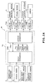
A control system of the sewing machine M will now be described. A
control device 70 of the sewing machine M includes a CPU 70a, a ROM 70b,
a RAM 70c, an input interface 70d, and an output interface 70e, as shown in
FIG. 14. To the input interface 70d are electrically connected the operation
switches 6, the touch panel 8, a main shaft rotational angle detecting sensor
71, and a cassette detecting switch 72. To the output interface 70e are
electrically connected the sewing machine motor 9, the pulse motor 44, the
liquid crystal display 17 and drive circuits 74a to 74d for driving the lamps
73. The control device 70 serves as a thread tension control in the
invention.
The ROM 70b stores a control program for the sewing machine M as
shown in FIG. 15. The control program includes a sewing control program
for sewing, a cassette attaching and detaching control program further
including a thread tension control program for attaching and detaching the
thread cassette 10 to and from the cassette mount 5 and a needle bar
position control program, and a display control program for displaying
various pieces of information on the liquid crystal display 7.
The cassette attaching and detaching control program includes a first
routine in which the thread tensioning mechanism 14 can be controlled so
that the thread 11 is tensioned a predetermined period of time (30 msec)
after detection of the thread cassette by the cassette detector. The
cassette attaching and detaching control program further includes a second
routine in which the thread tensioning mechanism 14 can be controlled so
that the tension of the thread 11 takes a predetermined value (for example,
0: open state).
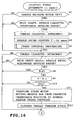
The control including a cassette attaching and detaching control
carried out by the control device 70 will now be described with reference to
FIGS. 16 and 17. Reference symbol "Si" where i=1, 2, 3 ···in each flowchart
designates an operation step. Steps S1 to S4 and S6 to S12 correspond to
the first routine and steps S14 to S19 correspond to the second routine. As
shown in FIG. 16, the control begins with an interrupt at intervals of 1 msec.
When the sewing machine motor 9 is stopped (S1) the control device 70
advances to step S2. When an angle of the main shaft is within a cassette
insertion angular range (S2: YES), the control device 70 advances to step S3.
When the cassette detecting switch 72 is turned on and accordingly, the
control device 70 determines that the thread cassette 10 has been attached
to the cassette mount 5 (S3: YES), the control device advances to step S4
where a needle swing counter T is set at 30 (msec) (S4), advancing to step
S5. When determining in the negative at each of steps S1 to S3, the control
device 70 thereafter advances to step S5.
A rotational angle of the main shaft is obtained by calculation on the
basis of information from a main shaft rotational angle detecting switch 71
comprising an encoder. In this case, a rotational angle of the main shaft is
zero (or 360°) when the main shaft is located at a needle upper position
which is an upper limit position of the needle bar 12 (needle 12a). The
cassette insertion angular range at step S2 is previously set at a range from
20 ° to 50°, for example.
The control device 70 advances to step S7 when a cassette detecting
switch 72 is in an ON state after other interval processing or when the
thread cassette 10 has been attached to the cassette mount 5 (S6: YES).
The control device 70 further advances to step S8 when the main shaft angle
is within a needle swing allowable angular range (S7: YES). The needle
swing allowable angular range at step S7 is basically determined as a one in
the case where the sewing needle 12a is located over the needle plate 1a,
for example, from 280° to 75°.
When the value of the counter T is not zero (S8: NO), the control
device 70 advances to step S9 to decrement the counter T to (T-1),
thereafter advancing to step S10. When the value of the counter T is zero
(S10: YES), the control device 70 advances to step S11. When determining
in the negative at each of steps S6 to S8 and S10, the control device 70
thereafter advances to step S13 (see FIG. 17).
When determining in the positive at step S10, the control device 70
advances to step S11 to start the pulse motor 44. The cam 13 is then
rotated to a position as shown in FIG. 13A, whereby the needle bar 12 is
moved from a cassette insertable position (or left needle position where the
threading can desirably be carried out by the threading mechanism 16) to a
normal needle swing position (for example, a neutral position where the
needle bar is vertical). With this, the control device 70 closes a pair of the
thread tensioning discs 41 and 42 at step S12, thereafter advancing to step
S13.
The control device 70 carries out the processing for stopping the
motor 9 (S16) when determining that the thread cassette 10 has been
detached from the cassette mount 5 (S14: YES), as shown in FIG. 17, after
other interval processing and further that the sewing machine motor 9 is in
operation (S15: YES). Thereafter, when determining that the main shaft
angle is within the aforesaid needle swing allowable angular range (S17:
YES), the control device 70 advances to step S18. The pulse motor 44 is
driven to rotate the cam 13 to the position as shown in FIG. 12A, at step S18.
As a result, the needle bar 12 is moved from the aforesaid normal needle
swing position to the aforesaid cassette insertable position. With this, the
control device 70 opens the thread tensioning discs 41 and 42 and thereafter
carrying out other interval processing (step S20), finishing the control.
When determining in the negative at each of steps S14 and S17, the control
device 70 thereafter advances to step S20.
As described above, the sewing machine M is provided with the
cassette mount 5 to which the thread cassette 10 having the thread
accommodating cavity 23 for accommodating the thread spool 22 therein is
detachably attached. The sewing machine M comprises the thread
tensioning mechanism 14 for adjusting the tension of the thread drawn from
the thread cassette 10, the cassette detecting switch 72 detecting the thread
cassette 10 having been attached to the cassette mount 5, and the control
device 70 controlling the thread tensioning mechanism 14 so that the thread
11 is tensioned a predetermined period of time (30 msec) after detection of
the thread cassette 10 by the cassette detecting switch 72.
Since the thread 11 drawn from the thread cassette 10 is tensioned by
the thread tensioning mechanism 14 upon lapse of the predetermined period
of time (30 msec) after detection of the thread cassette 10, the thread 11 can
reliably be placed on the thread tension shaft 40 and held by the thread
tensioning discs 41 and 42 of the thread tensioning mechanism 14. Thus,
the tension of the thread 11 drawn from the thread cassette 10 can be
adjusted reliably and desirably.
When the aforesaid predetermined period of time set is above 30
msec, the needle bar 12 displaced relative to attachment of the thread
cassette 10 would sometimes be moved from the cassette insertable
position to a needle swing position. This movement may frighten the user.
In the foregoing sewing machine, however, the predetermined period of time
is set at 30 msec, the needle bar 12 is operated substantially simultaneously
with attachment of the thread cassette 10. Consequently, the problem that
a sudden operation of the needle bar 12 frightens the user can be overcome.
Furthermore, the sewing machine M is provided with the detachment
operating member 60 operated so that the thread cassette 10 is detached
from the cassette mount 5. The control device 70 controls the thread
tensioning mechanism 14 so that the thread 11 is set at a predetermined
tension or more specifically, the thread tension discs 41 and 42 are opened
when the detachment operating member 60 has been operated.
According to the above-described arrangement, the thread tension
discs 41 and 42 are opened by the thread tensioning mechanism 14 under
control of the control device 70. Accordingly, since the thread 11 drawn
from the thread cassette 10 is reliably be released from the thread
tensioning mechanism 14, the thread can be prevented from being caught by
the thread tensioning mechanism. Since the thread cassette 10 is smoothly
detached from the cassette mount 5, the load imposed on the operator can
be reduced. Consequently, the tension of the thread drawn from the thread
cassette can be adjusted reliably and desirably.
Furthermore, the sewing machine M is further provided with the
thread tension releasing mechanism 15 operated in synchronization with the
detachment operating member 60 and opening the thread tension discs 41
and 42 when the detachment operating member has been operated. The
timing of thread tension release by the thread tension releasing mechanism
15 is set to occur earlier than the timing of opening the thread tension discs
by the control device 70, whereupon when the detachment operating
member 60 is operated, the thread tension discs 41 and 42 are rapidly
opened by the thread tensioning mechanism 14, whereupon the detachment
of the thread cassette 10 can desirably be coped with.
When power is disconnected from the sewing machine M and
accordingly, even when the control of the control device 70 for the thread
tensioning mechanism 14 is ineffective, the thread tension discs 41 and 42
can be opened when the detachment operating member 60 is operated.
Consequently, the thread cassette 10 can smoothly be detached from the
cassette mount 5 without the thread 11 being caught by the thread
tensioning mechanism 14.
Several modifications will be described. The thread cassette in the
foregoing embodiment is merely an example and accordingly, the thread
cassette should not be limited to the one including the thread source
comprising a thread spool or the like on which a thread is wound up. The
thread cassette may comprise a storing section in which a lump of thread
serving as a thread source is stored. Furthermore, at least one of walls
covering the thread storing section may be eliminated and a thread spool
may be held on a holding section such as a spool pin.
The thread releasing mechanism 15 may be eliminated and the thread
tensioning mechanism 14 may be constructed so as not to be opened by an
operating force applied to the detachment operating member 60 when the
member 60 is operated. Furthermore, a detecting switch may be provided
for directly detecting the detachment operating member 60 or indirectly
detecting detachment of the thread cassette 10 from the cassette mount 5,
and thread tensioning mechanism 14 may be controlled so that the thread
tension discs 41 and 42 are opened. Additionally, the foregoing
predetermined period of time may be set at various times (for example, 20
msec or 40 msec) other than 30 msec.
The thread tensioning mechanism 14 and the needle bar swinging
mechanism 19 need not be driven by a single pulse motor 44. These
mechanisms 14 and 19 may be provided with individual actuators such as
electric motors respectively. In this construction, when the user has
operated the sewing machine M to change the set thread tension, the
individual actuator for the thread tensioning mechanism 14 is operated so
that the changed thread tension is set. More specifically, the thread
tensioning mechanism 14 may be opened by an actuator automatically
changing the thread tension for the sewing at the time of detachment of the
thread cassette.
In the foregoing embodiment, the thread tensioning mechanism 14 is
opened so that the thread is not tensioned. However, the tension the thread
tensioning mechanism 14 applies to the thread may be rendered weaker (for
example, approximately zero), instead. In this case, too, substantially the
same effect can be achieved. The predetermined thread tension may refer
to the state where tension applied to the thread is weak or where no tension
is applied to the thread.
The control device 70 includes a ROM 70b storing a cassette
attachment and detachment control program including a thread tension
control program. The program may be applied to sewing machines similar
to the foregoing sewing machine M. More specifically, the cassette
attachment and detachment control program or the thread tension control
program may be supplied to users via an Internet or by means of a recording
medium, such as CD, MD and FD, on which the program is recorded.
The foregoing description and drawings are merely illustrative of the
principles of the present invention and are not to be construed in a limiting
sense. Various changes and modifications will become apparent to those of
ordinary skill in the art. All such changes and modifications are seen to fall
within the scope of the invention as defined by the appended claims.