EP1375397B1 - Apparatus and method for manipulating plate-shaped construction elements - Google Patents
Apparatus and method for manipulating plate-shaped construction elements Download PDFInfo
- Publication number
- EP1375397B1 EP1375397B1 EP03077046A EP03077046A EP1375397B1 EP 1375397 B1 EP1375397 B1 EP 1375397B1 EP 03077046 A EP03077046 A EP 03077046A EP 03077046 A EP03077046 A EP 03077046A EP 1375397 B1 EP1375397 B1 EP 1375397B1
- Authority
- EP
- European Patent Office
- Prior art keywords
- cams
- support
- construction elements
- stack
- construction
- Prior art date
- Legal status (The legal status is an assumption and is not a legal conclusion. Google has not performed a legal analysis and makes no representation as to the accuracy of the status listed.)
- Expired - Lifetime
Links
- 238000010276 construction Methods 0.000 title claims abstract description 87
- 238000000034 method Methods 0.000 title claims abstract description 9
- 238000012384 transportation and delivery Methods 0.000 claims abstract description 59
- 230000008878 coupling Effects 0.000 claims abstract description 3
- 238000010168 coupling process Methods 0.000 claims abstract description 3
- 238000005859 coupling reaction Methods 0.000 claims abstract description 3
- 238000004804 winding Methods 0.000 claims description 8
- 230000005484 gravity Effects 0.000 claims description 4
- 239000002184 metal Substances 0.000 claims description 3
- 125000006850 spacer group Chemical group 0.000 claims description 2
- 101100491335 Caenorhabditis elegans mat-2 gene Proteins 0.000 description 15
- 230000002787 reinforcement Effects 0.000 description 12
- 239000000725 suspension Substances 0.000 description 10
- 230000000284 resting effect Effects 0.000 description 3
- 230000000712 assembly Effects 0.000 description 2
- 238000000429 assembly Methods 0.000 description 2
- 239000011449 brick Substances 0.000 description 2
- 230000005540 biological transmission Effects 0.000 description 1
- 230000003247 decreasing effect Effects 0.000 description 1
- 230000000694 effects Effects 0.000 description 1
- 238000002955 isolation Methods 0.000 description 1
- 230000003014 reinforcing effect Effects 0.000 description 1
- 230000001360 synchronised effect Effects 0.000 description 1
Images


Classifications
-
- B—PERFORMING OPERATIONS; TRANSPORTING
- B65—CONVEYING; PACKING; STORING; HANDLING THIN OR FILAMENTARY MATERIAL
- B65G—TRANSPORT OR STORAGE DEVICES, e.g. CONVEYORS FOR LOADING OR TIPPING, SHOP CONVEYOR SYSTEMS OR PNEUMATIC TUBE CONVEYORS
- B65G61/00—Use of pick-up or transfer devices or of manipulators for stacking or de-stacking articles not otherwise provided for
-
- B—PERFORMING OPERATIONS; TRANSPORTING
- B65—CONVEYING; PACKING; STORING; HANDLING THIN OR FILAMENTARY MATERIAL
- B65G—TRANSPORT OR STORAGE DEVICES, e.g. CONVEYORS FOR LOADING OR TIPPING, SHOP CONVEYOR SYSTEMS OR PNEUMATIC TUBE CONVEYORS
- B65G47/00—Article or material-handling devices associated with conveyors; Methods employing such devices
- B65G47/74—Feeding, transfer, or discharging devices of particular kinds or types
- B65G47/90—Devices for picking-up and depositing articles or materials
-
- B—PERFORMING OPERATIONS; TRANSPORTING
- B65—CONVEYING; PACKING; STORING; HANDLING THIN OR FILAMENTARY MATERIAL
- B65G—TRANSPORT OR STORAGE DEVICES, e.g. CONVEYORS FOR LOADING OR TIPPING, SHOP CONVEYOR SYSTEMS OR PNEUMATIC TUBE CONVEYORS
- B65G59/00—De-stacking of articles
- B65G59/06—De-stacking from the bottom of the stack
- B65G59/061—De-stacking from the bottom of the stack articles being separated substantially along the axis of the stack
- B65G59/066—De-stacking from the bottom of the stack articles being separated substantially along the axis of the stack by means of rotary devices or endless elements
-
- B—PERFORMING OPERATIONS; TRANSPORTING
- B66—HOISTING; LIFTING; HAULING
- B66C—CRANES; LOAD-ENGAGING ELEMENTS OR DEVICES FOR CRANES, CAPSTANS, WINCHES, OR TACKLES
- B66C1/00—Load-engaging elements or devices attached to lifting or lowering gear of cranes or adapted for connection therewith for transmitting lifting forces to articles or groups of articles
- B66C1/10—Load-engaging elements or devices attached to lifting or lowering gear of cranes or adapted for connection therewith for transmitting lifting forces to articles or groups of articles by mechanical means
- B66C1/22—Rigid members, e.g. L-shaped members, with parts engaging the under surface of the loads; Crane hooks
- B66C1/28—Duplicate, e.g. pivoted, members engaging the loads from two sides
-
- B—PERFORMING OPERATIONS; TRANSPORTING
- B66—HOISTING; LIFTING; HAULING
- B66C—CRANES; LOAD-ENGAGING ELEMENTS OR DEVICES FOR CRANES, CAPSTANS, WINCHES, OR TACKLES
- B66C1/00—Load-engaging elements or devices attached to lifting or lowering gear of cranes or adapted for connection therewith for transmitting lifting forces to articles or groups of articles
- B66C1/10—Load-engaging elements or devices attached to lifting or lowering gear of cranes or adapted for connection therewith for transmitting lifting forces to articles or groups of articles by mechanical means
- B66C1/62—Load-engaging elements or devices attached to lifting or lowering gear of cranes or adapted for connection therewith for transmitting lifting forces to articles or groups of articles by mechanical means comprising article-engaging members of a shape complementary to that of the articles to be handled
-
- E—FIXED CONSTRUCTIONS
- E04—BUILDING
- E04G—SCAFFOLDING; FORMS; SHUTTERING; BUILDING IMPLEMENTS OR AIDS, OR THEIR USE; HANDLING BUILDING MATERIALS ON THE SITE; REPAIRING, BREAKING-UP OR OTHER WORK ON EXISTING BUILDINGS
- E04G21/00—Preparing, conveying, or working-up building materials or building elements in situ; Other devices or measures for constructional work
- E04G21/14—Conveying or assembling building elements
- E04G21/16—Tools or apparatus
- E04G21/169—Tools or apparatus specially adapted for working-up reinforcement mats
Definitions
- the invention relates to an apparatus for manipulating substantially plate-shaped construction elements.
- DE 27 30 626 discloses an apparatus, comprising a frame which is equipped with clamping means which can be brought into a clamping position around the circumferential edge of a layer of pavement bricks. This layer can then be picked up and transported to a position of use, where it can be released at a desired location. In this way, layers of bricks can be handled, one at the time, without substantial effort or manpower.
- the invention contemplates an apparatus for manipulating substantially plate-shaped construction elements, in which disadvantages of the known apparatuses are avoided while retaining the advantages thereof.
- an apparatus according to the invention is characterized by the measures according to claim 1.
- An apparatus enables a plurality of construction elements to be moved simultaneously to a desired location and to be delivered there one by one. In this manner, manpower can be saved and, moreover, the elements can be positioned fast, safely and accurately.
- a suitable cooperation between the support means and the delivery means each time allows a lowermost element of the stack to be isolated, so that this element is only supported by the delivery means.
- the isolated element can then be manipulated, in particular be released, without this having any effect on the remaining stack.
- the support and delivery means can each be provided with, for instance, two sets of cams, which cams are located above each other, which sets are each movable between a first, supporting position, in which the cams of the sets extend under the lowermost element and, for instance, the second lowermost element of the stack respectively, and a second, non-supporting position.
- the cams of the delivery and support means can, for instance, be driven by hydraulic drive means and are preferably remote-controllable, which promotes the safety of the apparatus. Each cam can then be driven separately, or the cams can be driven collectively, for instance per set, by a single drive means via transmission means suitable for this purpose. Collective driving can contribute to a simpler construction and control.
- At least a part of the moving order of the sets of first and second cams can be coupled, either mechanically or via control logic.
- control of the apparatus can be further simplified and, in addition, security measures can be built in, so that, for instance, the upper cams can only be moved to a non-supporting position if the lower cams are in a supporting position. This prevents the possibility of the entire stack of elements falling down all at once due to incorrect operation of the drive means and thus secures the safety of the apparatus even better.
- provisions can be made to be able to switch off such security settings, when such a delivery of a complete stack is desired, for instance when the apparatus is used to move the plate-shaped construction elements to an intermediate or storage location.
- an apparatus according to the invention is characterized by the measures according to claim 9.
- a taking-up function can, for instance, be achieved by designing the delivery and support means, in particular the sets of first and second cams thereof, such that their mutual positions are interchangeable viewed in vertical direction, for instance by means of lifting means.
- an element can be taken up from a base by moving a then lower set of cams under this element, after which the upper cams can be moved from a supporting position to a non-supporting position, while a stack located on these cams comes to rest on the element just taken up, after which these upper cams can be moved downwards by means of the lifting means under the other cams or at least under the then lowermost construction element, after which the next construction element can be taken up from a base, in the manner described hereinabove.
- an apparatus according to the invention is characterized by the measures according to claim 11.
- the delivery and support means are formed by a number of substantially vertically arranged screw spindles, where the construction elements are directly, or by intervention of suitable adaptor means, taken up between windings, preferably two successive windings, and can be transported upwards or downwards by synchronous rotation of the screw spindles, while the lowermost winding, at least adaptor, can take up or deliver an element.
- an apparatus according to the invention is particularly suitable for manipulating reinforcement mats manufactured, for instance welded, from wire.
- the support and delivery means can extend through meshes formed between the wires, or under the wires.
- an apparatus according to the invention is characterized by the measures according to claim 14.
- Suitable spacers can help to correctly position the support and delivery means within the meshes of the stack of reinforcement mats, that is, at a right distance from the surrounding wires, so that support and delivery means can adequately support these wires in a first position, are clear therefrom in a second position and further have sufficient freedom of movement to be able to move unhindered between the first and second position. In this manner, a proper and safe working of the apparatus can be guaranteed, in which the elements can, on the one hand, be adequately supported and cannot fall down unintentionally and can, on the other hand, be released without a hitch.
- the invention further relates to a method for manipulating substantially plate-shaped elements, characterized by the measures according to claim 17.
- Such a method enables relatively large and heavy construction elements to be manipulated in an efficient, time-saving manner, in which the elements are taken up at a first location, for instance a supply location, one by one or several at a time, are then moved to a second location and are delivered there, one by one or several at a time.
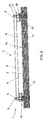
- Figs. 1-3 show a top plan view, front view and side view respectively of an apparatus for manipulating substantially plate-shaped construction elements, in particular reinforcement mats.
- a reinforcement mat is at least understood to be a mat 2 welded from wires, in particular metal longitudinal and cross wires 11, 13, as shown in Fig. 1, which longitudinal and cross wires 11, 13 extend substantially perpendicular to each other and are interconnected at their cross points.
- Such reinforcement or construction mats 2 are frequently used in construction for reinforcing concrete constructions and, depending on their use, can have a considerable size and corresponding weight. This generally makes the mats 2 difficult to manipulate.
- An apparatus 1 improves this, in that it allows a stack of mats 2 to be taken up and moved together to a location of use, where the mats 2 can be delivered one by one.
- the apparatus 1 comprises a frame 3 and four sets of support and delivery devices 10A-D, located near four angular points of the frame 3.
- the frame 3 is built up from two parallel longitudinal beams 4, which are interconnected near their ends by suspension beams 5 and are, at some distance from these ends, connected by at least two cross beams 6.
- the suspension beams 5 project on both sides of the longitudinal beams 4 and, approximately at the height of the cross beams 6, are connected at their projecting ends to the longitudinal beams 4 via inclined support beams 7.
- a rigid, truss-like frame 3 is formed, which acts as a suspension construction for the support and delivery means 10A-D yet to be discussed.
- each suspension beam 5 is provided, near its ends, with an eye 8, which allows the frame 3 to be suspended, in use, from a crane, crab or like means of transport.
- a subframe 15 is suspended, in each of which, two sets of support and delivery means 10A,B and 10C,D are placed.
- the subframes 15 each comprise two box-shaped end parts 12 interconnected by two parallel support beams 14 extending into the end parts 12.
- Each box-shaped end part 12 comprises a pentagonal bottom plate 16, pentagonal cover plate 17 and raised walls 18 extending around these plates 16, 17.
- the cover plates 17 are provided, on an outside, with a bracket 20, by means of which the end parts 12 and consequently the subframes 15 are suspended from the ends of the suspension beam 5, with the subframe 15 extending substantially parallel to the suspension beam 5.
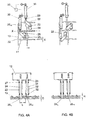
- the support and delivery means 10A-D are the same for all four angular points of the frame 3, and will therefore hereinafter be described with reference to one set (namely the set indicated by 10D in Fig. 1). In the Figs. 4A, B, this set is shown, enlarged, in top plan and side view, for two different to be discussed hereinafter.
- the support and delivery means 10 comprise two substantially equally long, circular tube parts 22, which are each fixed, using a flange 23, on an outside of the bottom plate 16 of end part 12, substantially perpendicular thereto.
- the tube parts 22 are arranged on both sides of two imaginary, vertical planes X, Y (see Fig. 1), of which the X plane extends substantially perpendicular to the suspension beam 5, at the height of the suspension brackets 20, and the Y plane extends substantially perpendicular to the X plane, at the height of, or at least near the eyes 8.
- the tube parts 22 are each provided, on a side proximal to the X plane, with a rib 29 which extends throughout virtually the entire length of the tube parts 22 and, in the exemplary embodiment shown, has the shape of a substantially rectangular box beam.
- a rod-shaped part 24 is placed in a pivotable manner, for instance by means of one or more bearings.
- These rod-shaped parts 24 are each provided, at a first end, with a cam 25 extending in radial direction, which projects outside the tube parts 22, which, for this purpose, can be provided with suitable slotted openings at the height of these cams 25.
- an upper side 32 of one cam hereinafter designated as 25 H , functioning as a supporting surface, is located, viewed in axial direction, a distance H higher than the upper side 32 of the other cam, hereinafter to be designated as 25 L , with H being approximately equal to a diameter d of the wires 11, 13 of the reinforcement mats 2.
- the cams 25 H,L have, in top plan view, a substantially rectangular form, which approximately corresponds to the diameter of the ribs 29, for a reason which will be discussed later. Further, in side view, the cams 25 H,L preferably have a slightly wedge-shaped configuration, with the thickness D of the cams slightly decreasing in the direction of the free edges and being, at least at these edges, slightly smaller than d, with d again representing the diameter of the reinforcement wires 11, 13.
- the rod-shaped parts 24 extend by a second end into the box-shaped end part 12, through the bottom plate 16, and there, they are each connected to a piston rod 28 of a piston assembly 30 via a drive arm 26.
- the piston assemblies 30 are fixedly arranged in the box-shaped end part 12, substantially parallel to the suspension beam 5 and are remote-controllable via control means 33.
- the stroke of the piston rod 28 and the dimensions of the drive arm 26 are chosen such that, upon a complete stroke of the piston rod 28, the rod-shaped parts 24 can be rotated through an angle of approximately 90°.
- the cams 25 H,L can then pivot from a first position, as shown in Fig.
- the described apparatus 1 can be used as follows for manipulating a stack of reinforcement mats 2.
- the apparatus 1 is suspended from the eyes 8 from, for instance, a crane, hoist truck, crab or like means of transport. In this manner, the apparatus 1 is positioned above a stack of reinforcement mats 2 at, for instance, a storage or supply location. Then, the apparatus 1 is lowered using the means of transport or hoisting means (not shown) provided between the means of transport and the apparatus 1, with the support and delivery means 10A-D extending through the meshes of the stacked mats 2, as shown in Fig. 2.
- the piston rods 28 are maximally extended and thus, the cams 25 H,L are in their second position in or under the ribs 29 (see Fig. 4B).
- the ribs 29 contribute to a correct positioning of the support and delivery means 10, in particular the cams 25 H,L in the meshes, in that the ribs 29 keep the cams 25 H,L at a sufficient distance, viewed in the Y direction, from a cross wire 11 extending between the support and delivery means 10. This will prevent the cams 25 from coming into contact with this cross wire 11, so they will not be damaged and maintain their freedom to pivot to the first position.
- the radial length L of the cams 25 and the mutual distance between the ribs 29, viewed in the X direction, is chosen such that the cams 25 H,L can always extend, in their first position, beyond a longitudinal wire 13 extending between the ribs 29, so that the cams will always be able to adequately support the mats 2.
- the ribs 29 limit an angle through which the mats 2 may be rotated relative to the support and delivery means 10, seen in top plan view. This also guarantees an adequate support of the wires 13 by the cams 25.
- the lower cams 25 L are pivoted to the first position using the piston assemblies 30, so these cams 25 L will extend under a cross wire 11 of the lowermost mat 2 of the stack to be taken up, as shown in Fig. 2.
- the stack of reinforcement mats 2 now rests on four cams 25 L .
- the apparatus 1 can take up ten mats 2 at once. It will be clear, however, that the maximum number of construction mats 2 to be taken up can be varied as desired, determined by inter alia the length of the tube parts 22, the thickness of the construction mats 2 and the bearing capacity of the apparatus 1.
- the stack of construction mats 2 resting on the lower cams 25 L can then, using the means of transport, be transported to a desired location where the mats 2 can be delivered one by one.
- the lowermost construction mat 2 is first isolated from the superjacent construction mats by pivoting the upper cams 25 H from their second position under the ribs 29 (see Fig. 4B) to their first position, by retracting the respective piston rods 28.
- the cams 25 H thanks to their wedge shape and maximum thickness d, can be simply slid between two cross wires 13 located one above the other of the lowermost and the second lowermost construction mat 2, since these cross wires 13, due to the longitudinal wires 11 located therebetween, are at a mutual distance d from each other.
- the apparatus 1 can then be prepared for delivery of a next, then lowermost construction mat, by successively pivoting the lower cams 25 L back to their first (supporting) position and pivoting the upper cams 25 H from under the stack to the second position, so that the stack resting until then on these upper cams 25 H is then transferred to the lower cams 25 L .
- the new lowermost mat can be isolated from the superjacent mats and delivered in the manner described hereinabove.
- the complete stack can be delivered one by one, while, if desired, the apparatus 1 can each time be moved over a certain distance between the deliveries of the individual construction mats 2, so that the mats 2 can be laid down at a desired position.
- the apparatus 1 can be used to manipulate a next stack of construction mats in the manner described hereinabove for the purpose of destacking that next stack.
- the drives of the set of lower and the set of upper cams 25 L,H are preferably at least partly coupled, either through mechanical means or through electronic control means.
- This coupling can, for instance, be arranged such that the upper cams 25 H can only be moved to the second, non-supporting position if the lower cams 25 L are in the first, supporting position or when no construction mats are included in the apparatus 1.
- the cams 25 H,L are further remote-controllable, allowing an operator to be at a safe distance when delivering the mats.
- the support and delivery means 10 can be arranged along the edges of these elements, so that the cams 25 H,L , in their first position, can engage under the edges of these elements. Also, when, for instance, the elements to be moved are relatively large and flexible and thus deflect strongly, a plurality of sets of support and delivery means 10 can be used.
- the support and delivery means 10 are preferably adjustably connected to the frame 3, allowing their mutual position to be adapted to the dimensions and the specific shape of the construction elements to be manipulated, for instance the length, width, mesh width and the shape of the meshes.
- the mutual height distance H between the lower and the upper cams 25 H,L is also adjustable, allowing this distance to be adapted to the thickness of the object to be manipulated.
- This distance H can, of course, also be adjusted such that it allows more than one element of the superjacent stack to be isolated, and thus also allows more than one element to be delivered. Adjusting the mutual cam position can be done once only or repeatedly, manually or using drive means.
- the apparatus shown in the Figs. 1-4 also allows construction elements 2 to be taken up one by one.
- the cams 25 H,L can be arranged so as to be movable in vertical direction by means of suitable lifting means (not shown), such that their mutual vertical positions can be interchanged.
- This allows a lower set of cams to take up a first mat from a base, by pivoting these cams 25 L under the mat, in the manner described hereinabove.
- the mat 2 can then be lifted by approximately a mat thickness using the means of transport, after which the upper cams 25 H can be moved downwards, using the lifting means, under the, until then, lower cams 25 L .
- cams 25 H can then be pivoted, in the known manner, under a second mat 2 to be taken up. Then, the cams 25 L can first be pivoted from under the mat taken up first, causing this mat to fall down on the mat taken up second. The cams 25 L can then be moved downwards, using the lifting means, under the mat taken up second, after which a next mat can be taken up, in the manner described.
- the lifting means can, for instance, comprise a guide rail, in which the cams can be moved upwards and downwards using, for instance, an electromotor.
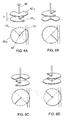
- the support and delivery means 10 can be designed as substantially vertically arranged screw spindles 35, as shown in Fig. 5.
- Such screw spindles can be arranged pair-wise opposite each other in a similar manner to the support and delivery means 10 described hereinabove, near two edges opposite each other of a construction element 2, or in case of a construction mat 2, near two cross or longitudinal wires 13, 11 located at a distance from each other.
- these edges or wires 13, 11 are taken up between successive windings 37.
- each screw spindle 35 preferably a rod-shaped element is arranged, which extends parallel to and at a short distance from this screw spindle 35. In this manner, cross or longitudinal wires 13, 11 extending between the windings 37 can be locked against the screw spindle, preventing them from slipping out of the windings 37.
- the support and delivery means 10 can be designed as shown in Fig. 6.
- a set of support and delivery means 10 is formed by a vertically arranged bar 40, which is provided, near a lower side, with two cams 42 H,L located one above the other.
- the cams 42 H,L are disc-shaped, missing a quarter of the circle segment.
- the cams 42 H,L are non-rotatably connected to the bar 40 such that the missing circle segments are rotated approximately 90° relative to each other.
- the mutual distance H between the cams is approximately equal to the thickness of the construction elements 2 to be manipulated, that is, in the case shown, the diameter of the wires 13.
- the cams 42 H,L are preferably provided so as to be slidable on the bar 40 such that the distance H can be adjusted as desired.
- a tube (not shown) can be provided, in which the bar can be pivotally bearing-mounted. This tube can then fulfill a same function as the tube parts 22 and ribs 29 in the embodiment shown in the Figs. 1-4, that is, to ensure that the support and delivery means are always at the right distance from the edge or wires 11,13 to be supported, so that the cams can move unhindered between a supporting and releasing position.
- the bars 40 with the cams 42 H,L can be arranged, in a manner similar to that described with reference to the previous embodiments, near an edge or wire 13, 11 of a construction element to be manipulated.
- a stack of construction elements 2 placed on the upper cams 42 H can be delivered one by one through rotation of the bar 40.
- the bar 40 with the cams 42 H,L is shown in perspective view and in top plan view.
- the upper cams 42 H are shown in continuous lines and the lower cams 42 L in interrupted lines.
- the lower cams 42 L are shown slightly smaller than the upper cams 42 H .
- the two cams 42 H,L preferably have the same dimensions.
- the upper cam 42 H In a first position (Fig. 6A), the upper cam 42 H extends under a cross wire 13 of a construction mat 2, and the cam 42 H can thus support this construction mat 2 or a stack of construction mats 2.
- the bar 40 When the bar 40 is rotated from this position through 90°, as shown in Fig. 6B, the missing circle segment is rotated in the direction of the cross wire 13, and the wire 13 is no longer supported. This will cause the mat or stack of mats to fall down one position on the lower cams 42 L .
- the bar 40 is further rotated through another 90° (Fig. 6C)
- the upper cam 42 H will slide between a lowermost and a second lowermost mat 2 and this cam 42 H thus takes over the stack of mats above the lowermost mat 2 from the lower cam 42 L .
- the bar 40 is rotated further to the starting position shown in Fig. 6A and the lowermost mat is isolated from the rest of the stack between the two cams 42 H,L , ready to be delivered.
- This delivery is done at the moment when the bar 40 is pivoted from the position shown in Fig. 6D to the position shown in Fig. 6A.
- the missing circle segment is maneuvered under the wire 13, so this wire is no longer supported by the cam 42 L and the construction mat is released while the superjacent stack is still supported by the upper cam 42 H .
- one piston assembly or other suitable drive means is sufficient. This contributes to a robust arrangement, which can, moreover, be safely and simply controlled, since the successive movements of the cams 42 H,L are mechanically fixed.
- the upper sides of the cams 42 H,L can be provided with friction-reducing means, such as, for instance, rollers, in order to facilitate the movement of the cams 42 H,L under the stack of construction elements.
- drive means other than the hydraulic drive means shown can be used, for instance electric or pneumatic drive means.
- a plurality of sets of cams can be placed above each other, allowing a plurality of elements to be isolated from the stack.
- the cams can also be arranged translatably around a substantially horizontal axis, with the cams being pivoted from a substantially horizontal, supporting position to a substantially vertical, non-supporting position.
- the cams can also be arranged so as to be translatable.
Landscapes
- Engineering & Computer Science (AREA)
- Mechanical Engineering (AREA)
- Architecture (AREA)
- Civil Engineering (AREA)
- Structural Engineering (AREA)
- De-Stacking Of Articles (AREA)
- Conveying And Assembling Of Building Elements In Situ (AREA)
- Sheets, Magazines, And Separation Thereof (AREA)
- Bending Of Plates, Rods, And Pipes (AREA)
Abstract
Description
- The invention relates to an apparatus for manipulating substantially plate-shaped construction elements.
- In construction, relatively sizeable and proportionally heavy plate-shaped parts, such as prefab panels or reinforcement mats welded from metal wire, regularly need to be moved from a supply or storage location to an actual location of use. When the distances to be covered are relatively small, moving is often done manually. This takes up much manpower, since often at least four men are needed per element, and is, moreover, quite often in violation of the current health and safety laws with regard to the working conditions. Also, the elements can be moved between the two locations using a crane, hoist truck or like means of transport. An advantage thereof is that these enable a stack of construction elements to be moved simultaneously. A disadvantage is that the elements need to be destacked at their destination, which still requires considerable manpower and time.
- DE 27 30 626 discloses an apparatus, comprising a frame which is equipped with clamping means which can be brought into a clamping position around the circumferential edge of a layer of pavement bricks. This layer can then be picked up and transported to a position of use, where it can be released at a desired location. In this way, layers of bricks can be handled, one at the time, without substantial effort or manpower.
- The invention contemplates an apparatus for manipulating substantially plate-shaped construction elements, in which disadvantages of the known apparatuses are avoided while retaining the advantages thereof. For this purpose, an apparatus according to the invention is characterized by the measures according to claim 1.
- An apparatus according to the invention enables a plurality of construction elements to be moved simultaneously to a desired location and to be delivered there one by one. In this manner, manpower can be saved and, moreover, the elements can be positioned fast, safely and accurately.
- A suitable cooperation between the support means and the delivery means each time allows a lowermost element of the stack to be isolated, so that this element is only supported by the delivery means. The isolated element can then be manipulated, in particular be released, without this having any effect on the remaining stack.
- The isolation and release of the lowermost element can be realized using relatively simple means, while, moreover, the force of gravity can be used in an advantageous manner. For instance, the support and delivery means can each be provided with, for instance, two sets of cams, which cams are located above each other, which sets are each movable between a first, supporting position, in which the cams of the sets extend under the lowermost element and, for instance, the second lowermost element of the stack respectively, and a second, non-supporting position. By moving the two sets of cams in the right order between these positions, each time the lowermost element can be isolated from the stack and released, while the superjacent elements will fall down one position under the force of gravity and the apparatus is ready for delivery of the next element.
- The cams of the delivery and support means can, for instance, be driven by hydraulic drive means and are preferably remote-controllable, which promotes the safety of the apparatus. Each cam can then be driven separately, or the cams can be driven collectively, for instance per set, by a single drive means via transmission means suitable for this purpose. Collective driving can contribute to a simpler construction and control.
- Further, at least a part of the moving order of the sets of first and second cams can be coupled, either mechanically or via control logic. In this manner, the control of the apparatus can be further simplified and, in addition, security measures can be built in, so that, for instance, the upper cams can only be moved to a non-supporting position if the lower cams are in a supporting position. This prevents the possibility of the entire stack of elements falling down all at once due to incorrect operation of the drive means and thus secures the safety of the apparatus even better. Of course, provisions can be made to be able to switch off such security settings, when such a delivery of a complete stack is desired, for instance when the apparatus is used to move the plate-shaped construction elements to an intermediate or storage location.
- In a further advantageous elaboration, an apparatus according to the invention is characterized by the measures according to claim 9.
- Adjusting the support and delivery means such that these can also take up construction elements individually yields an apparatus which has an even wider range of application. Such a taking-up function can, for instance, be achieved by designing the delivery and support means, in particular the sets of first and second cams thereof, such that their mutual positions are interchangeable viewed in vertical direction, for instance by means of lifting means. In this manner, an element can be taken up from a base by moving a then lower set of cams under this element, after which the upper cams can be moved from a supporting position to a non-supporting position, while a stack located on these cams comes to rest on the element just taken up, after which these upper cams can be moved downwards by means of the lifting means under the other cams or at least under the then lowermost construction element, after which the next construction element can be taken up from a base, in the manner described hereinabove.
- In an alternative embodiment, an apparatus according to the invention is characterized by the measures according to
claim 11. - In this embodiment, the delivery and support means are formed by a number of substantially vertically arranged screw spindles, where the construction elements are directly, or by intervention of suitable adaptor means, taken up between windings, preferably two successive windings, and can be transported upwards or downwards by synchronous rotation of the screw spindles, while the lowermost winding, at least adaptor, can take up or deliver an element.
- In a further elaboration, an apparatus according to the invention is particularly suitable for manipulating reinforcement mats manufactured, for instance welded, from wire. Here, the support and delivery means can extend through meshes formed between the wires, or under the wires.
- In a particularly advantageous embodiment, an apparatus according to the invention is characterized by the measures according to
claim 14. - Suitable spacers can help to correctly position the support and delivery means within the meshes of the stack of reinforcement mats, that is, at a right distance from the surrounding wires, so that support and delivery means can adequately support these wires in a first position, are clear therefrom in a second position and further have sufficient freedom of movement to be able to move unhindered between the first and second position. In this manner, a proper and safe working of the apparatus can be guaranteed, in which the elements can, on the one hand, be adequately supported and cannot fall down unintentionally and can, on the other hand, be released without a hitch.
- The invention further relates to a method for manipulating substantially plate-shaped elements, characterized by the measures according to
claim 17. - Such a method enables relatively large and heavy construction elements to be manipulated in an efficient, time-saving manner, in which the elements are taken up at a first location, for instance a supply location, one by one or several at a time, are then moved to a second location and are delivered there, one by one or several at a time.
- In the further subclaims, further advantageous embodiments of an apparatus and method according to the invention are described.
- To clarify the invention, exemplary embodiments of an apparatus according to the invention as well as the use thereof will be explained with reference to the drawing, in which:
- Fig. 1 shows a top plan view of an apparatus according to the invention, provided with a stack of construction mats;
- Fig. 2 shows a front view of the apparatus of Fig. 1;
- Fig. 3 shows a side view of the apparatus of Fig. 1;
- Fig. 4A shows, enlarged, a top plan view and side view of a set of support and delivery means of the apparatus of Fig. 1, in a first position;
- Fig. 4B shows the delivery means of Fig. 4A, in a second position;
- Fig. 5 shows an alternative embodiment of a set of support and delivery means according to the invention, designed as a screw spindle; and
- Figs. 6A-D show a second alternative embodiment of a set of support and delivery means according to the invention, designed as a pivotal rod with two cams located one above the other.
- The Figs. 1-3 show a top plan view, front view and side view respectively of an apparatus for manipulating substantially plate-shaped construction elements, in particular reinforcement mats.
- In this description, a reinforcement mat is at least understood to be a
mat 2 welded from wires, in particular metal longitudinal andcross wires cross wires construction mats 2 are frequently used in construction for reinforcing concrete constructions and, depending on their use, can have a considerable size and corresponding weight. This generally makes themats 2 difficult to manipulate. - An apparatus 1 according to the invention improves this, in that it allows a stack of
mats 2 to be taken up and moved together to a location of use, where themats 2 can be delivered one by one. For this purpose, the apparatus 1 comprises aframe 3 and four sets of support anddelivery devices 10A-D, located near four angular points of theframe 3. - The
frame 3 is built up from two parallellongitudinal beams 4, which are interconnected near their ends bysuspension beams 5 and are, at some distance from these ends, connected by at least twocross beams 6. Thesuspension beams 5 project on both sides of thelongitudinal beams 4 and, approximately at the height of thecross beams 6, are connected at their projecting ends to thelongitudinal beams 4 viainclined support beams 7. Thus, a rigid, truss-like frame 3 is formed, which acts as a suspension construction for the support and delivery means 10A-D yet to be discussed. For this purpose, eachsuspension beam 5 is provided, near its ends, with aneye 8, which allows theframe 3 to be suspended, in use, from a crane, crab or like means of transport. - From each
suspension beam 5, asubframe 15 is suspended, in each of which, two sets of support and delivery means 10A,B and 10C,D are placed. Thesubframes 15 each comprise two box-shaped end parts 12 interconnected by twoparallel support beams 14 extending into theend parts 12. Each box-shaped end part 12 comprises apentagonal bottom plate 16,pentagonal cover plate 17 andraised walls 18 extending around theseplates cover plates 17 are provided, on an outside, with abracket 20, by means of which theend parts 12 and consequently thesubframes 15 are suspended from the ends of thesuspension beam 5, with thesubframe 15 extending substantially parallel to thesuspension beam 5. - The support and delivery means 10A-D are the same for all four angular points of the
frame 3, and will therefore hereinafter be described with reference to one set (namely the set indicated by 10D in Fig. 1). In the Figs. 4A, B, this set is shown, enlarged, in top plan and side view, for two different to be discussed hereinafter. - The support and delivery means 10 comprise two substantially equally long,
circular tube parts 22, which are each fixed, using aflange 23, on an outside of thebottom plate 16 ofend part 12, substantially perpendicular thereto. Thetube parts 22 are arranged on both sides of two imaginary, vertical planes X, Y (see Fig. 1), of which the X plane extends substantially perpendicular to thesuspension beam 5, at the height of thesuspension brackets 20, and the Y plane extends substantially perpendicular to the X plane, at the height of, or at least near theeyes 8. - The
tube parts 22 are each provided, on a side proximal to the X plane, with arib 29 which extends throughout virtually the entire length of thetube parts 22 and, in the exemplary embodiment shown, has the shape of a substantially rectangular box beam. - Within each
tube part 22, a rod-shapedpart 24 is placed in a pivotable manner, for instance by means of one or more bearings. These rod-shapedparts 24 are each provided, at a first end, with acam 25 extending in radial direction, which projects outside thetube parts 22, which, for this purpose, can be provided with suitable slotted openings at the height of thesecams 25. Here, anupper side 32 of one cam, hereinafter designated as 25H, functioning as a supporting surface, is located, viewed in axial direction, a distance H higher than theupper side 32 of the other cam, hereinafter to be designated as 25L, with H being approximately equal to a diameter d of thewires reinforcement mats 2. Thecams 25H,L have, in top plan view, a substantially rectangular form, which approximately corresponds to the diameter of theribs 29, for a reason which will be discussed later. Further, in side view, thecams 25H,L preferably have a slightly wedge-shaped configuration, with the thickness D of the cams slightly decreasing in the direction of the free edges and being, at least at these edges, slightly smaller than d, with d again representing the diameter of thereinforcement wires - Furthermore, the rod-shaped
parts 24 extend by a second end into the box-shapedend part 12, through thebottom plate 16, and there, they are each connected to apiston rod 28 of apiston assembly 30 via adrive arm 26. Thepiston assemblies 30 are fixedly arranged in the box-shapedend part 12, substantially parallel to thesuspension beam 5 and are remote-controllable via control means 33. The stroke of thepiston rod 28 and the dimensions of thedrive arm 26 are chosen such that, upon a complete stroke of thepiston rod 28, the rod-shapedparts 24 can be rotated through an angle of approximately 90°. Thecams 25H,L can then pivot from a first position, as shown in Fig. 4A, in which thepiston rod 28 is virtually completely retracted and the cams extend in the direction of the Y plane, substantially perpendicular thereto, to a second position, as shown in Fig. 4B, in which thepiston rod 28 has reached its extreme position and thecams 25H,L are located substantially in line with theribs 29. Here, the earlier-mentioned design of thecams 25H,L ensures that, in this second position, the cams do not project in relation to the outer contour of therib 29. The advantage of this will be discussed later. - The described apparatus 1 can be used as follows for manipulating a stack of
reinforcement mats 2. The apparatus 1 is suspended from theeyes 8 from, for instance, a crane, hoist truck, crab or like means of transport. In this manner, the apparatus 1 is positioned above a stack ofreinforcement mats 2 at, for instance, a storage or supply location. Then, the apparatus 1 is lowered using the means of transport or hoisting means (not shown) provided between the means of transport and the apparatus 1, with the support and delivery means 10A-D extending through the meshes of thestacked mats 2, as shown in Fig. 2. Here, thepiston rods 28 are maximally extended and thus, thecams 25H,L are in their second position in or under the ribs 29 (see Fig. 4B). - The
ribs 29 contribute to a correct positioning of the support and delivery means 10, in particular thecams 25H,L in the meshes, in that theribs 29 keep thecams 25H,L at a sufficient distance, viewed in the Y direction, from across wire 11 extending between the support and delivery means 10. This will prevent thecams 25 from coming into contact with thiscross wire 11, so they will not be damaged and maintain their freedom to pivot to the first position. - The radial length L of the
cams 25 and the mutual distance between theribs 29, viewed in the X direction, is chosen such that thecams 25H,L can always extend, in their first position, beyond alongitudinal wire 13 extending between theribs 29, so that the cams will always be able to adequately support themats 2. Further, theribs 29 limit an angle through which themats 2 may be rotated relative to the support and delivery means 10, seen in top plan view. This also guarantees an adequate support of thewires 13 by thecams 25. - After the support and delivery means 10 have thus been inserted into the stack of
reinforcement mats 2, thelower cams 25L are pivoted to the first position using thepiston assemblies 30, so thesecams 25L will extend under across wire 11 of thelowermost mat 2 of the stack to be taken up, as shown in Fig. 2. The stack ofreinforcement mats 2 now rests on fourcams 25L. In the example shown, in this manner, the apparatus 1 can take up tenmats 2 at once. It will be clear, however, that the maximum number ofconstruction mats 2 to be taken up can be varied as desired, determined by inter alia the length of thetube parts 22, the thickness of theconstruction mats 2 and the bearing capacity of the apparatus 1. - The stack of
construction mats 2 resting on thelower cams 25L can then, using the means of transport, be transported to a desired location where themats 2 can be delivered one by one. For this purpose, thelowermost construction mat 2 is first isolated from the superjacent construction mats by pivoting theupper cams 25H from their second position under the ribs 29 (see Fig. 4B) to their first position, by retracting therespective piston rods 28. Here, thecams 25H, thanks to their wedge shape and maximum thickness d, can be simply slid between twocross wires 13 located one above the other of the lowermost and the secondlowermost construction mat 2, since thesecross wires 13, due to thelongitudinal wires 11 located therebetween, are at a mutual distance d from each other. - In this manner, the stack of construction mats above the lowermost construction mat is taken over by the
upper cams 25H and thelower cams 25L only support thelowermost construction mat 2. Thislowermost construction mat 2 is then delivered by pivoting thelower cams 25L from under thisconstruction mat 2 to their second position. This will cause thelowermost construction mat 2 to fall down under the force of gravity. Optionally, guide means (not shown) can be provided so that this falling down takes place in a controlled manner. The apparatus 1 can then be prepared for delivery of a next, then lowermost construction mat, by successively pivoting thelower cams 25L back to their first (supporting) position and pivoting theupper cams 25H from under the stack to the second position, so that the stack resting until then on theseupper cams 25H is then transferred to thelower cams 25L. After this, the new lowermost mat can be isolated from the superjacent mats and delivered in the manner described hereinabove. By repeating the above steps again and again, the complete stack can be delivered one by one, while, if desired, the apparatus 1 can each time be moved over a certain distance between the deliveries of theindividual construction mats 2, so that themats 2 can be laid down at a desired position. After destacking the stack ofmats 2, the apparatus 1 can be used to manipulate a next stack of construction mats in the manner described hereinabove for the purpose of destacking that next stack. - The drives of the set of lower and the set of
upper cams 25L,H are preferably at least partly coupled, either through mechanical means or through electronic control means. This coupling can, for instance, be arranged such that theupper cams 25H can only be moved to the second, non-supporting position if thelower cams 25L are in the first, supporting position or when no construction mats are included in the apparatus 1. This has the result that a stack of mats resting on theupper cams 25H cannot fall down from the apparatus unintentionally, for instance due to incorrect operation. In this manner, the safety of the apparatus is increased. Of course, such a protection can be removed if desired when one does want to be able to deliver a stack of elements at once. Thecams 25H,L are further remote-controllable, allowing an operator to be at a safe distance when delivering the mats. - It will be clear that other plate-shaped elements than the construction mats shown can also be manipulated using an apparatus 1 according to the invention, for instance plate-shaped prefab parts such as floor and wall parts. In that case, the support and delivery means 10 can be arranged along the edges of these elements, so that the
cams 25H,L, in their first position, can engage under the edges of these elements. Also, when, for instance, the elements to be moved are relatively large and flexible and thus deflect strongly, a plurality of sets of support and delivery means 10 can be used. - The support and delivery means 10 are preferably adjustably connected to the
frame 3, allowing their mutual position to be adapted to the dimensions and the specific shape of the construction elements to be manipulated, for instance the length, width, mesh width and the shape of the meshes. Preferably, the mutual height distance H between the lower and theupper cams 25H,L is also adjustable, allowing this distance to be adapted to the thickness of the object to be manipulated. This distance H can, of course, also be adjusted such that it allows more than one element of the superjacent stack to be isolated, and thus also allows more than one element to be delivered. Adjusting the mutual cam position can be done once only or repeatedly, manually or using drive means. - In an alternative embodiment, the apparatus shown in the Figs. 1-4 also allows
construction elements 2 to be taken up one by one. For this purpose, thecams 25H,L can be arranged so as to be movable in vertical direction by means of suitable lifting means (not shown), such that their mutual vertical positions can be interchanged. This allows a lower set of cams to take up a first mat from a base, by pivoting thesecams 25L under the mat, in the manner described hereinabove. Themat 2 can then be lifted by approximately a mat thickness using the means of transport, after which theupper cams 25H can be moved downwards, using the lifting means, under the, until then,lower cams 25L. Thesecams 25H can then be pivoted, in the known manner, under asecond mat 2 to be taken up. Then, thecams 25L can first be pivoted from under the mat taken up first, causing this mat to fall down on the mat taken up second. Thecams 25L can then be moved downwards, using the lifting means, under the mat taken up second, after which a next mat can be taken up, in the manner described. The lifting means can, for instance, comprise a guide rail, in which the cams can be moved upwards and downwards using, for instance, an electromotor. - In an alternative embodiment, the support and delivery means 10 can be designed as substantially vertically arranged
screw spindles 35, as shown in Fig. 5. Such screw spindles can be arranged pair-wise opposite each other in a similar manner to the support and delivery means 10 described hereinabove, near two edges opposite each other of aconstruction element 2, or in case of aconstruction mat 2, near two cross orlongitudinal wires wires successive windings 37. By driving thescrew spindles 35, the construction elements will, depending on the drive direction, move upwards or downwards and the lowermost winding 38 will each time take up, or deliver an element. - When
such screw spindles 35 are used for manipulatingconstruction mats 2, next to eachscrew spindle 35 preferably a rod-shaped element is arranged, which extends parallel to and at a short distance from thisscrew spindle 35. In this manner, cross orlongitudinal wires windings 37 can be locked against the screw spindle, preventing them from slipping out of thewindings 37. - In a further alternative embodiment, the support and delivery means 10 can be designed as shown in Fig. 6. In this variant, a set of support and delivery means 10 is formed by a vertically arranged
bar 40, which is provided, near a lower side, with twocams 42H,L located one above the other. Thecams 42H,L are disc-shaped, missing a quarter of the circle segment. Thecams 42H,L are non-rotatably connected to thebar 40 such that the missing circle segments are rotated approximately 90° relative to each other. The mutual distance H between the cams is approximately equal to the thickness of theconstruction elements 2 to be manipulated, that is, in the case shown, the diameter of thewires 13. Thecams 42H,L are preferably provided so as to be slidable on thebar 40 such that the distance H can be adjusted as desired. Around thebar 40, a tube (not shown) can be provided, in which the bar can be pivotally bearing-mounted. This tube can then fulfill a same function as thetube parts 22 andribs 29 in the embodiment shown in the Figs. 1-4, that is, to ensure that the support and delivery means are always at the right distance from the edge orwires - The
bars 40 with thecams 42H,L can be arranged, in a manner similar to that described with reference to the previous embodiments, near an edge orwire construction elements 2 placed on theupper cams 42H can be delivered one by one through rotation of thebar 40. This will be clarified with reference to the Figs. 6A-D, in which one rotation of thebar 40 is illustrated in four successive steps, with thebar 40 being rotated through 90° in each step. For each step, thebar 40 with thecams 42H,L is shown in perspective view and in top plan view. In this top plan view, theupper cams 42H are shown in continuous lines and thelower cams 42L in interrupted lines. In addition, for reasons of clarity, thelower cams 42L are shown slightly smaller than theupper cams 42H. In reality, the twocams 42H,L preferably have the same dimensions. - In a first position (Fig. 6A), the
upper cam 42H extends under across wire 13 of aconstruction mat 2, and thecam 42H can thus support thisconstruction mat 2 or a stack ofconstruction mats 2. When thebar 40 is rotated from this position through 90°, as shown in Fig. 6B, the missing circle segment is rotated in the direction of thecross wire 13, and thewire 13 is no longer supported. This will cause the mat or stack of mats to fall down one position on thelower cams 42L. When, thereupon, thebar 40 is further rotated through another 90° (Fig. 6C), theupper cam 42H will slide between a lowermost and a secondlowermost mat 2 and thiscam 42H thus takes over the stack of mats above thelowermost mat 2 from thelower cam 42L. During the fourth and last step of the rotation, thebar 40 is rotated further to the starting position shown in Fig. 6A and the lowermost mat is isolated from the rest of the stack between the twocams 42H,L, ready to be delivered. This delivery is done at the moment when thebar 40 is pivoted from the position shown in Fig. 6D to the position shown in Fig. 6A. In this manner, the missing circle segment is maneuvered under thewire 13, so this wire is no longer supported by thecam 42L and the construction mat is released while the superjacent stack is still supported by theupper cam 42H. By thus rotating thebar 40, through cooperation of thecams 42H,L, each time an element is isolated from the stack and then delivered. - In an embodiment as described hereinabove, per set of support and delivery means 10, one piston assembly or other suitable drive means is sufficient. This contributes to a robust arrangement, which can, moreover, be safely and simply controlled, since the successive movements of the
cams 42H,L are mechanically fixed. - Optionally, the upper sides of the
cams 42H,L can be provided with friction-reducing means, such as, for instance, rollers, in order to facilitate the movement of thecams 42H,L under the stack of construction elements. - The invention is by no means limited to the exemplary embodiments shown in the description and the drawing. Many variations thereof are possible within the scope of the invention as set forth in the claims.
- For instance, drive means other than the hydraulic drive means shown can be used, for instance electric or pneumatic drive means. Further, a plurality of sets of cams can be placed above each other, allowing a plurality of elements to be isolated from the stack. Further, instead of being arranged pivotally around a substantially vertical axis, as shown in the embodiments, the cams can also be arranged translatably around a substantially horizontal axis, with the cams being pivoted from a substantially horizontal, supporting position to a substantially vertical, non-supporting position. The cams can also be arranged so as to be translatable.
- These and many variations are considered to be within the scope of the invention as set forth in the claims following hereinafter.
Claims (20)
- An apparatus for manipulating substantially plate-shaped construction elements (2), comprising a frame (3), provided with coupling means (8) for fixing the frame (3) to means of transport for moving the frame (3), support means (10) for taking up and supporting a series of construction elements (2) and delivery means (10) for delivery of the construction elements (2), characterized by the fact that during use the construction elements (2) are taken up into the support means (25H; 37; 42H) in stacked form, and the delivery means (25L, 38, 42L) can be operated so as to be arranged at least partly under the support means (25H; 37; 42H), in particular the stack of construction elements (2) taken up therein, wherein the support (25H; 37; 42H) and delivery means (25L, 38, 42L) can cooperate in such a manner as to enable a lowermost element of the stack to be transferred from the support means (25H; 37; 42H) to the delivery means (25L, 38, 42L), thereby isolating said lowermost element of the stack, after which this element can be released by the delivery means, thus enable the construction elements (2) to be delivered one by one.
- An apparatus according to claim 1, wherein the support means (25H; 37; 42H) are arranged such that, after delivery of a lowermost construction element, the remaining, superjacent construction elements (2) move down one position.
- An apparatus according to claim 2, wherein the support means (25H; 37; 42H) are arranged such that the moving down of the construction elements (2) takes place under the force of gravity.
- An apparatus according to any one of the preceding claims, wherein the support and delivery means (10) comprise a set of first cams (25H) and a set of second cams (25L), which cams (25H,L) are, per set, movable independently of each other between a first, supporting position in which the first and second cams (25H,L) form a first and a second support surface respectively, which are located one above the other and can each support at least a part of a stack of construction elements (2), and a second, release position, in which the sets of cams (25H,L) do not support the construction elements (2), at least a part thereof.
- An apparatus according to claim 4, wherein the perpendicular distance (H) between the first and second support surface (25H,L) is approximately equal to and preferably slightly greater than the thickness (d) of one plate-shaped construction element (2).
- An apparatus according to claim 4 or 5, wherein the first and/or the second cams (25H,L) are pivotable between the first and second position.
- An apparatus according to claim 4 or 5, wherein the first and/or the second cams (25H,L) are translatable between the first and second position.
- An apparatus according to any one of claims 4-7, wherein the movements of the set of first cams (25H; 42H) and the set of second cams (25L, 42L) are coupled, such that the upper set of cams (25H; 42H) can only be moved from the first, supporting position to the second, release position, if the lower set of cams (25L, 42L) is in the first, supporting position.
- An apparatus according to any one of the preceding claims, wherein the support and delivery means (10) are arranged such that they enable the plate-shaped construction elements (2) to be taken up one by one, wherein the delivery means are arranged to engage and pick up a construction element and the support means are arranged to support a stack of construction elements picked up earlier and wherein the support and delivery means are arranged to cooperate, so as to enable the construction element picked up by the delivery means to be transferred to the support means so as to form part of the stack supported by said support means, thereby freeing the delivery means to pick up a subsequent construction element.
- An apparatus according to any one of claims 5 - 9, wherein the first and second cams (25H,L) are supported by lifting means, so that their mutual positions, viewed in vertical direction, are interchangeable, for taking up construction elements (2) one by one.
- An apparatus according to claim 1, wherein the support and delivery means (10) comprise substantially vertically arranged screw spindles (35), wherein, between windings (37; 38), taking-up positions for the construction elements (2) have been formed and wherein the construction elements (2), through rotation of the screw spindles (35), can move one place each time and, depending on the direction of rotation, a lowermost taking-up position (38) takes up, or delivers a construction element (2).
- An apparatus according to any one of the preceding claims, wherein the delivery and/or the support means (10) are driven by remote-controllable drive means (30).
- An apparatus according to claim 12, wherein the drive means (30) comprise at least one pneumatic or hydraulic cylinder assembly.
- An assembly of an apparatus according to any one of the preceding claims and a series of substantially plate-shaped elements (2), characterized by the fact that the support and delivery means (10) are set up near an edge of the construction elements (2).
- An assembly of an apparatus according to any one of claims 1-134 and a series of substantially plate-shaped elements (2), characterized by the fact that the plate-shaped construction elements (2) are manufactured from metal wire- (11, 13) and the support and delivery means (10) extend through meshes between these wires 11, 13), wherein the first and second cams (25L,H; 37; 42L,H) in the first position engage under or behind said wires (11, 13).
- An assembly according to claim 15, wherein spacers (29) are provided, for maintaining a desired distance between the support and delivery means (10) and the wires (11, 13) of the construction elements (2), so that movement of the first and second cams (25L,H; 37; 42L,H) between the first and second position is possible unhindered and the cams can, in a first position, extend at least partly under a wire (11, 13) and, in a second position, are located within a mesh.
- A method for manipulating substantially plate-shaped construction elements (2) with an apparatus according to any one of claims 1-134, characterized by the fact that the construction elements (2) are taken up one by one or per stack, are moved to a desired location and are then delivered one by one, in reverse order of taking-up.
- A method according to claim 17, wherein a stack of construction elements (2) is delivered one by one by means of at least two sets of movable cams (25L,H; 37; 42L,H), comprising the following steps:- moving a first set of cams (25L, 38, 42L) to a first position, in which the cams extend at least partly under a lowermost construction element of the stack;- moving a second set of cams (25H; 37; 42H) to a first position, between a lowermost element (2) of the stack and a superjacent element;- moving the first set of cams (25L, 38, 42L) to a second, non-supporting position, thereby delivering the lowermost element (2);- moving back the first set of cams (25L, 38, 42L) to a first, supporting position;- moving the second set of cams (25H; 37; 42H) to a second position, thereby bringing at least the lowermost construction element (2) of the remaining stack down onto the first set of cams; after which the above steps can be repeated until all elements have been delivered.
- A method according to claim 18, wherein the first and second set of cams are first brought in the second position before the cams are brought into and/or to the stack of construction elements to be manipulated, wherein the stack is then delivered via the said steps.
- A method according to claim 18 or 19, wherein, after all elements of the said stack have been delivered, a next stack of construction elements is delivered, using the cams, via the said steps.
Applications Claiming Priority (2)
| Application Number | Priority Date | Filing Date | Title |
|---|---|---|---|
| NL1020961 | 2002-06-28 | ||
| NL1020961A NL1020961C1 (en) | 2002-06-28 | 2002-06-28 | Device and method for manipulating plate-shaped structural elements. |
Publications (2)
| Publication Number | Publication Date |
|---|---|
| EP1375397A1 EP1375397A1 (en) | 2004-01-02 |
| EP1375397B1 true EP1375397B1 (en) | 2006-08-30 |
Family
ID=29717743
Family Applications (1)
| Application Number | Title | Priority Date | Filing Date |
|---|---|---|---|
| EP03077046A Expired - Lifetime EP1375397B1 (en) | 2002-06-28 | 2003-06-30 | Apparatus and method for manipulating plate-shaped construction elements |
Country Status (4)
| Country | Link |
|---|---|
| EP (1) | EP1375397B1 (en) |
| AT (1) | ATE337991T1 (en) |
| DE (1) | DE60307933T2 (en) |
| NL (1) | NL1020961C1 (en) |
Cited By (3)
| Publication number | Priority date | Publication date | Assignee | Title |
|---|---|---|---|---|
| CN102862776A (en) * | 2011-07-05 | 2013-01-09 | 上海耐斯特液压设备有限公司 | Stepping type heavy-load slipping movement equipment |
| EP4502311A1 (en) * | 2023-08-04 | 2025-02-05 | Wilhelmus Van Eekeres | Mobile system for placing insulation boards |
| EP4517027A1 (en) * | 2023-08-30 | 2025-03-05 | The Roberts BV | A device for lifting at least one flat cementitious material reinforcement product |
Families Citing this family (6)
| Publication number | Priority date | Publication date | Assignee | Title |
|---|---|---|---|---|
| NL1032461C2 (en) * | 2006-09-08 | 2008-03-12 | Sybe Bergsma | Equipment and method are for manipulation of reinforcement mats in particular |
| IT1396186B1 (en) * | 2009-09-23 | 2012-11-16 | Pigazzi Reti S R L | MANIPULATOR FOR NETWORKS. |
| NL2015175B1 (en) * | 2015-07-15 | 2017-02-02 | Van Middendorp Montage B V | Supporting device for carrying a stack of roofing sheets. |
| JP6553565B2 (en) * | 2016-09-09 | 2019-07-31 | 育良精機株式会社 | Bar conveying device |
| CN111606045B (en) * | 2019-09-26 | 2021-12-24 | 大连华枝金属制品制造有限公司 | Rectangular iron wire frame feeding device |
| CN114291725B (en) * | 2021-12-24 | 2023-03-10 | 中国建筑第二工程局有限公司 | Hoisting clamping device for assembly type building and using method |
Family Cites Families (4)
| Publication number | Priority date | Publication date | Assignee | Title |
|---|---|---|---|---|
| CH446403A (en) * | 1967-02-10 | 1967-11-15 | Moll Robert | Device for the automatic distribution one by one of publications arranged in a stack |
| DE2730626C3 (en) * | 1977-07-07 | 1980-05-29 | Oldenburger Betonsteinwerke Gmbh, 2906 Wardenburg | Gripper for combining a layer of paving stones into a laying unit |
| CH654274A5 (en) * | 1983-06-13 | 1986-02-14 | Rochat Charles L | AUTOMATIC DISPENSER FOR FLAT RIGID PARTS. |
| IT1309756B1 (en) * | 1999-04-29 | 2002-01-30 | Clevertech Srl | EQUIPMENT FOR FORMING STACKS OF DISCOID OBJECTS IN PRE-FIXED NUMBER, IN PARTICULAR FOR METAL LIDS OF JARS |
-
2002
- 2002-06-28 NL NL1020961A patent/NL1020961C1/en not_active IP Right Cessation
-
2003
- 2003-06-30 AT AT03077046T patent/ATE337991T1/en not_active IP Right Cessation
- 2003-06-30 DE DE60307933T patent/DE60307933T2/en not_active Expired - Fee Related
- 2003-06-30 EP EP03077046A patent/EP1375397B1/en not_active Expired - Lifetime
Cited By (5)
| Publication number | Priority date | Publication date | Assignee | Title |
|---|---|---|---|---|
| CN102862776A (en) * | 2011-07-05 | 2013-01-09 | 上海耐斯特液压设备有限公司 | Stepping type heavy-load slipping movement equipment |
| EP4502311A1 (en) * | 2023-08-04 | 2025-02-05 | Wilhelmus Van Eekeres | Mobile system for placing insulation boards |
| NL2035553B1 (en) * | 2023-08-04 | 2025-02-18 | Van Eekeres Wilhelmus | Mobile system for placing insulation boards |
| EP4517027A1 (en) * | 2023-08-30 | 2025-03-05 | The Roberts BV | A device for lifting at least one flat cementitious material reinforcement product |
| WO2025045852A1 (en) * | 2023-08-30 | 2025-03-06 | The Roberts Bv | A device for lifting at least one flat cementitious material reinforcement product |
Also Published As
| Publication number | Publication date |
|---|---|
| DE60307933D1 (en) | 2006-10-12 |
| EP1375397A1 (en) | 2004-01-02 |
| DE60307933T2 (en) | 2007-06-06 |
| ATE337991T1 (en) | 2006-09-15 |
| NL1020961C1 (en) | 2003-12-30 |
Similar Documents
| Publication | Publication Date | Title |
|---|---|---|
| EP1375397B1 (en) | Apparatus and method for manipulating plate-shaped construction elements | |
| US12509331B2 (en) | Device for lifting a steel reinforcement mat | |
| EP4446079A2 (en) | Machine for removing formwork from ceiling structure | |
| EP2071081A1 (en) | Paving machine | |
| DK2700597T3 (en) | An apparatus and method for stacking or destacking of boxes | |
| CA2188842C (en) | Apparatus for storing and transporting long workpieces | |
| EP2505713B1 (en) | Method and assembly for repaving | |
| KR101048036B1 (en) | Electric hoist | |
| CN213536599U (en) | Loading pile up neatly device and pile up neatly machine of breaking a jam | |
| EP3322867B1 (en) | Set and method for delivering a stack of roof covering panels at a location of use | |
| KR102530301B1 (en) | Bending apparatus for pipe | |
| JPS62293084A (en) | Automatic device for lining inner wall of vessel by brick | |
| US5184924A (en) | Method and equipment for transferring concrete slabs | |
| JP7519135B1 (en) | Transporting and installing blocks | |
| JP2952338B2 (en) | Scaffold cleaning equipment | |
| AU622994B2 (en) | Electrode handling system and machine | |
| WO2004007841A2 (en) | Apparatus for laying metallic railway sleepers | |
| US4081089A (en) | Arrangement for handling and preparation of base plates and the like such as, for example, casting molds | |
| GB2433955A (en) | Method of laying a plurality of railway sleepers | |
| CN118704493A (en) | A highway arched skeleton slope protection brick lifting and paving device | |
| CN115744745B (en) | Method for removing roof returning member | |
| US3292509A (en) | Picking device for mesh placing machine | |
| US20160068356A1 (en) | System and Method for Reusing or Recycling Building Material | |
| JPH10226489A (en) | Forming and conveying system for architectural plates | |
| JP2872044B2 (en) | Lifting equipment for structural members |
Legal Events
| Date | Code | Title | Description |
|---|---|---|---|
| PUAI | Public reference made under article 153(3) epc to a published international application that has entered the european phase |
Free format text: ORIGINAL CODE: 0009012 |
|
| AK | Designated contracting states |
Kind code of ref document: A1 Designated state(s): AT BE BG CH CY CZ DE DK EE ES FI FR GB GR HU IE IT LI LU MC NL PT RO SE SI SK TR |
|
| AX | Request for extension of the european patent |
Extension state: AL LT LV MK |
|
| 17P | Request for examination filed |
Effective date: 20040702 |
|
| AKX | Designation fees paid |
Designated state(s): AT BE BG CH CY CZ DE DK EE ES FI FR GB GR HU IE IT LI LU MC NL PT RO SE SI SK TR |
|
| 17Q | First examination report despatched |
Effective date: 20041208 |
|
| GRAP | Despatch of communication of intention to grant a patent |
Free format text: ORIGINAL CODE: EPIDOSNIGR1 |
|
| GRAS | Grant fee paid |
Free format text: ORIGINAL CODE: EPIDOSNIGR3 |
|
| GRAA | (expected) grant |
Free format text: ORIGINAL CODE: 0009210 |
|
| AK | Designated contracting states |
Kind code of ref document: B1 Designated state(s): AT BE BG CH CY CZ DE DK EE ES FI FR GB GR HU IE IT LI LU MC NL PT RO SE SI SK TR |
|
| PG25 | Lapsed in a contracting state [announced via postgrant information from national office to epo] |
Ref country code: AT Free format text: LAPSE BECAUSE OF FAILURE TO SUBMIT A TRANSLATION OF THE DESCRIPTION OR TO PAY THE FEE WITHIN THE PRESCRIBED TIME-LIMIT Effective date: 20060830 Ref country code: LI Free format text: LAPSE BECAUSE OF FAILURE TO SUBMIT A TRANSLATION OF THE DESCRIPTION OR TO PAY THE FEE WITHIN THE PRESCRIBED TIME-LIMIT Effective date: 20060830 Ref country code: BE Free format text: LAPSE BECAUSE OF FAILURE TO SUBMIT A TRANSLATION OF THE DESCRIPTION OR TO PAY THE FEE WITHIN THE PRESCRIBED TIME-LIMIT Effective date: 20060830 Ref country code: RO Free format text: LAPSE BECAUSE OF FAILURE TO SUBMIT A TRANSLATION OF THE DESCRIPTION OR TO PAY THE FEE WITHIN THE PRESCRIBED TIME-LIMIT Effective date: 20060830 Ref country code: CZ Free format text: LAPSE BECAUSE OF FAILURE TO SUBMIT A TRANSLATION OF THE DESCRIPTION OR TO PAY THE FEE WITHIN THE PRESCRIBED TIME-LIMIT Effective date: 20060830 Ref country code: SI Free format text: LAPSE BECAUSE OF FAILURE TO SUBMIT A TRANSLATION OF THE DESCRIPTION OR TO PAY THE FEE WITHIN THE PRESCRIBED TIME-LIMIT Effective date: 20060830 Ref country code: SK Free format text: LAPSE BECAUSE OF FAILURE TO SUBMIT A TRANSLATION OF THE DESCRIPTION OR TO PAY THE FEE WITHIN THE PRESCRIBED TIME-LIMIT Effective date: 20060830 Ref country code: CH Free format text: LAPSE BECAUSE OF FAILURE TO SUBMIT A TRANSLATION OF THE DESCRIPTION OR TO PAY THE FEE WITHIN THE PRESCRIBED TIME-LIMIT Effective date: 20060830 Ref country code: FI Free format text: LAPSE BECAUSE OF FAILURE TO SUBMIT A TRANSLATION OF THE DESCRIPTION OR TO PAY THE FEE WITHIN THE PRESCRIBED TIME-LIMIT Effective date: 20060830 Ref country code: IT Free format text: LAPSE BECAUSE OF FAILURE TO SUBMIT A TRANSLATION OF THE DESCRIPTION OR TO PAY THE FEE WITHIN THE PRESCRIBED TIME-LIMIT;WARNING: LAPSES OF ITALIAN PATENTS WITH EFFECTIVE DATE BEFORE 2007 MAY HAVE OCCURRED AT ANY TIME BEFORE 2007. THE CORRECT EFFECTIVE DATE MAY BE DIFFERENT FROM THE ONE RECORDED. Effective date: 20060830 |
|
| REG | Reference to a national code |
Ref country code: GB Ref legal event code: FG4D |
|
| REG | Reference to a national code |
Ref country code: CH Ref legal event code: EP |
|
| REG | Reference to a national code |
Ref country code: IE Ref legal event code: FG4D |
|
| REF | Corresponds to: |
Ref document number: 60307933 Country of ref document: DE Date of ref document: 20061012 Kind code of ref document: P |
|
| PG25 | Lapsed in a contracting state [announced via postgrant information from national office to epo] |
Ref country code: DK Free format text: LAPSE BECAUSE OF FAILURE TO SUBMIT A TRANSLATION OF THE DESCRIPTION OR TO PAY THE FEE WITHIN THE PRESCRIBED TIME-LIMIT Effective date: 20061130 Ref country code: BG Free format text: LAPSE BECAUSE OF FAILURE TO SUBMIT A TRANSLATION OF THE DESCRIPTION OR TO PAY THE FEE WITHIN THE PRESCRIBED TIME-LIMIT Effective date: 20061130 Ref country code: SE Free format text: LAPSE BECAUSE OF FAILURE TO SUBMIT A TRANSLATION OF THE DESCRIPTION OR TO PAY THE FEE WITHIN THE PRESCRIBED TIME-LIMIT Effective date: 20061130 |
|
| PG25 | Lapsed in a contracting state [announced via postgrant information from national office to epo] |
Ref country code: ES Free format text: LAPSE BECAUSE OF FAILURE TO SUBMIT A TRANSLATION OF THE DESCRIPTION OR TO PAY THE FEE WITHIN THE PRESCRIBED TIME-LIMIT Effective date: 20061211 |
|
| PG25 | Lapsed in a contracting state [announced via postgrant information from national office to epo] |
Ref country code: PT Free format text: LAPSE BECAUSE OF FAILURE TO SUBMIT A TRANSLATION OF THE DESCRIPTION OR TO PAY THE FEE WITHIN THE PRESCRIBED TIME-LIMIT Effective date: 20070212 |
|
| REG | Reference to a national code |
Ref country code: CH Ref legal event code: PL |
|
| EN | Fr: translation not filed | ||
| PLBE | No opposition filed within time limit |
Free format text: ORIGINAL CODE: 0009261 |
|
| STAA | Information on the status of an ep patent application or granted ep patent |
Free format text: STATUS: NO OPPOSITION FILED WITHIN TIME LIMIT |
|
| 26N | No opposition filed |
Effective date: 20070531 |
|
| PG25 | Lapsed in a contracting state [announced via postgrant information from national office to epo] |
Ref country code: MC Free format text: LAPSE BECAUSE OF NON-PAYMENT OF DUE FEES Effective date: 20070630 |
|
| PG25 | Lapsed in a contracting state [announced via postgrant information from national office to epo] |
Ref country code: GR Free format text: LAPSE BECAUSE OF FAILURE TO SUBMIT A TRANSLATION OF THE DESCRIPTION OR TO PAY THE FEE WITHIN THE PRESCRIBED TIME-LIMIT Effective date: 20061201 Ref country code: FR Free format text: LAPSE BECAUSE OF FAILURE TO SUBMIT A TRANSLATION OF THE DESCRIPTION OR TO PAY THE FEE WITHIN THE PRESCRIBED TIME-LIMIT Effective date: 20070511 |
|
| PG25 | Lapsed in a contracting state [announced via postgrant information from national office to epo] |
Ref country code: EE Free format text: LAPSE BECAUSE OF FAILURE TO SUBMIT A TRANSLATION OF THE DESCRIPTION OR TO PAY THE FEE WITHIN THE PRESCRIBED TIME-LIMIT Effective date: 20060830 |
|
| PGFP | Annual fee paid to national office [announced via postgrant information from national office to epo] |
Ref country code: BE Payment date: 20080416 Year of fee payment: 6 |
|
| PG25 | Lapsed in a contracting state [announced via postgrant information from national office to epo] |
Ref country code: IE Free format text: LAPSE BECAUSE OF NON-PAYMENT OF DUE FEES Effective date: 20070702 |
|
| PGFP | Annual fee paid to national office [announced via postgrant information from national office to epo] |
Ref country code: DE Payment date: 20080819 Year of fee payment: 6 Ref country code: NL Payment date: 20080618 Year of fee payment: 6 |
|
| PG25 | Lapsed in a contracting state [announced via postgrant information from national office to epo] |
Ref country code: FR Free format text: LAPSE BECAUSE OF FAILURE TO SUBMIT A TRANSLATION OF THE DESCRIPTION OR TO PAY THE FEE WITHIN THE PRESCRIBED TIME-LIMIT Effective date: 20060830 |
|
| PGFP | Annual fee paid to national office [announced via postgrant information from national office to epo] |
Ref country code: GB Payment date: 20080617 Year of fee payment: 6 |
|
| PG25 | Lapsed in a contracting state [announced via postgrant information from national office to epo] |
Ref country code: LU Free format text: LAPSE BECAUSE OF NON-PAYMENT OF DUE FEES Effective date: 20070630 Ref country code: CY Free format text: LAPSE BECAUSE OF FAILURE TO SUBMIT A TRANSLATION OF THE DESCRIPTION OR TO PAY THE FEE WITHIN THE PRESCRIBED TIME-LIMIT Effective date: 20060830 |
|
| PG25 | Lapsed in a contracting state [announced via postgrant information from national office to epo] |
Ref country code: TR Free format text: LAPSE BECAUSE OF FAILURE TO SUBMIT A TRANSLATION OF THE DESCRIPTION OR TO PAY THE FEE WITHIN THE PRESCRIBED TIME-LIMIT Effective date: 20060830 Ref country code: HU Free format text: LAPSE BECAUSE OF FAILURE TO SUBMIT A TRANSLATION OF THE DESCRIPTION OR TO PAY THE FEE WITHIN THE PRESCRIBED TIME-LIMIT Effective date: 20070301 |
|
| BERE | Be: lapsed |
Owner name: BOUW & HANDELMIJ. NIJKERK B.V. Effective date: 20090630 |
|
| GBPC | Gb: european patent ceased through non-payment of renewal fee |
Effective date: 20090630 |
|
| NLV4 | Nl: lapsed or anulled due to non-payment of the annual fee |
Effective date: 20100101 |
|
| PG25 | Lapsed in a contracting state [announced via postgrant information from national office to epo] |
Ref country code: GB Free format text: LAPSE BECAUSE OF NON-PAYMENT OF DUE FEES Effective date: 20090630 |
|
| PG25 | Lapsed in a contracting state [announced via postgrant information from national office to epo] |
Ref country code: BE Free format text: LAPSE BECAUSE OF FAILURE TO SUBMIT A TRANSLATION OF THE DESCRIPTION OR TO PAY THE FEE WITHIN THE PRESCRIBED TIME-LIMIT Effective date: 20090630 Ref country code: DE Free format text: LAPSE BECAUSE OF NON-PAYMENT OF DUE FEES Effective date: 20100101 |
|
| PG25 | Lapsed in a contracting state [announced via postgrant information from national office to epo] |
Ref country code: NL Free format text: LAPSE BECAUSE OF NON-PAYMENT OF DUE FEES Effective date: 20100101 |