EP1375346A2 - Evacuation slide having trapezoidal outline - Google Patents
Evacuation slide having trapezoidal outline Download PDFInfo
- Publication number
- EP1375346A2 EP1375346A2 EP03007599A EP03007599A EP1375346A2 EP 1375346 A2 EP1375346 A2 EP 1375346A2 EP 03007599 A EP03007599 A EP 03007599A EP 03007599 A EP03007599 A EP 03007599A EP 1375346 A2 EP1375346 A2 EP 1375346A2
- Authority
- EP
- European Patent Office
- Prior art keywords
- main support
- escape slide
- support tube
- inflatable
- head end
- Prior art date
- Legal status (The legal status is an assumption and is not a legal conclusion. Google has not performed a legal analysis and makes no representation as to the accuracy of the status listed.)
- Withdrawn
Links
- 238000000034 method Methods 0.000 description 3
- 238000010276 construction Methods 0.000 description 1
- 238000007796 conventional method Methods 0.000 description 1
- 230000006378 damage Effects 0.000 description 1
- 238000004880 explosion Methods 0.000 description 1
- 230000001788 irregular Effects 0.000 description 1
- 238000012986 modification Methods 0.000 description 1
- 230000004048 modification Effects 0.000 description 1
- 238000009877 rendering Methods 0.000 description 1
- XLYOFNOQVPJJNP-UHFFFAOYSA-N water Substances O XLYOFNOQVPJJNP-UHFFFAOYSA-N 0.000 description 1
Images


Classifications
-
- B—PERFORMING OPERATIONS; TRANSPORTING
- B64—AIRCRAFT; AVIATION; COSMONAUTICS
- B64D—EQUIPMENT FOR FITTING IN OR TO AIRCRAFT; FLIGHT SUITS; PARACHUTES; ARRANGEMENT OR MOUNTING OF POWER PLANTS OR PROPULSION TRANSMISSIONS IN AIRCRAFT
- B64D25/00—Emergency apparatus or devices, not otherwise provided for
- B64D25/08—Ejecting or escaping means
- B64D25/14—Inflatable escape chutes
-
- A—HUMAN NECESSITIES
- A62—LIFE-SAVING; FIRE-FIGHTING
- A62B—DEVICES, APPARATUS OR METHODS FOR LIFE-SAVING
- A62B1/00—Devices for lowering persons from buildings or the like
- A62B1/20—Devices for lowering persons from buildings or the like by making use of sliding-ropes, sliding-poles or chutes, e.g. hoses, pipes, sliding-grooves, sliding-sheets
Definitions
- This invention relates to emergency evacuation equipment for aircraft, in particular, to inflatable aircraft evacuation slides.
- U.S. Patent No. 5,820,773 to Hintzman, et al. teaches use of a support tube that prevents the evacuation slide from being blown underneath the aircraft during deployment.
- U.S. Patent No. 5,102,070 to Smialowicz, et al. teaches use of an inflatable structure that extends into the slide enclosure to provide a rigid mount to help prevent the head end of the slide from twisting out of position.
- 3,811,534 to Fisher teaches an oil platform evacuation slide that uses a plurality of guy straps extending at angles outward from the foot end of the inflatable escape slide to head end attachments that are spaced apart substantially wider than the head end of the slide.
- the guy straps create a trapezoid truss arrangement, which provides for substantial resistance against deformation of the slide under windloads.
- Use of external guy straps to create a truss for securing the evacuation slide against lateral deformation under wind loads is very effective for evacuation slides for use with oil platforms and the like where the exposed guy straps are mounted to a stationary structure.
- Use of external guy straps on an aircraft evacuation slide would be disfavored by most aircraft manufactures because of the need to provide concealed mounting points outside of the evacuation slide packboard enclosure. According, what is needed is an aircraft evacuation slide having the lateral stability inherent in a trapezoidal truss, without the need for externally mounted guy stays.
- the present invention satisfies the foregoing need by providing an inflatable evacuation slide the main support tubes of which form a trapezoidal truss-like structure.
- the inflatable evacuation slide comprises a pair of main support tubes supporting a flexible sliding surface.
- the main support tubes taper from a widest point near the exit opening of the aircraft to a narrowest point at the foot end of the slide.
- the escape slide may extend normally outward from the aircraft fuselage such that the head end transverse tube and the toe end transverse tube are parallel, in which case the escape slide is a true trapezoid.
- the escape slide may extend out at an angle from the aircraft fuselage, in which case the head end tube and the toe end tube are not parallel and one of the main support tubes is longer than the other. In the latter case the escape slide is not a true trapezoid but is an irregular quadrilateral (or as used herein, a quasi-trapezoid).
- the non-parallel main support tubes that taper towards each other as they extend outward from the aircraft provide a highly stable structure not found in prior art rectangular evacuation slides.
- FIG. 1 shows an inflatable evacuation slide system 10 incorporating features of the present invention.
- Slide system 10 includes an inflatable evacuation slide 12 and an inflator 14 which may be a conventional pyrotechnic, compressed gas, or hybrid inflator well-known in the art.
- Inflatable evacuation slide system 10 is stored in an undeployed condition in a packboard housing inside the fuselage of aircraft 16.
- inflatable evacuation slide 12 In a deployed condition, inflatable evacuation slide 12 extends from a location proximal the egress opening 18 of aircraft 16 toward the ground level 20 or other lower supporting surface.
- inflatable evacuation slide 12 comprises upper main support tubes 22 and 26 and lower main support tubes 24 and 28 supporting a flexible sliding surface 30.
- Flexible sliding surface 30 is composed of a left main panel 32, a right main panel 34, a foot end panel 36, a left upper panel 38, a right upper panel 40 and a head end panel 42.
- the head end 44 of inflatable evacuation slide 12 is secured to aircraft 16 by a convention girt 46.
- Upper main support tubes 22 and 26 are maintained in a spaced-apart configuration by an upper toe end transverse tube 48 located at the foot end 50 of inflatable evacuation slide 12 and an upper head end transverse tube 52 located at head end 44 of inflatable evacuation slide 12.
- Lower main support tubes 24 and 28 are similarly maintained in spaced-apart configuration by lower toe end transverse tube 54 at foot end 50 of inflatable evacuation slide 12 and lower head end transverse tube located at head end 44 of inflatable evacuation slide 12.
- a center support tube 58 bisects flexible sliding surface 30 to create two substantially parallel slides.
- a lateral support tube 60 provides additional support for head end 44 of inflatable evacuation slide 12.
- a lower truss tube 62 and an upper truss tube 64 each of which comprises a U-shaped tube extending from lower main support tube 24 to lower main support tube 28.
- lower truss tube 62 and upper truss tube 64 comprise E-shaped tubes interconnecting lower main support to tube 24, lower main support tube 28 and center support tube 58.
- a plurality of truss straps 66 act as tension members to support inflatable evacuation slide 12 against buckling under heavy load.
- upper main support tubes 22 and 26 each have in plan view an axial center line 72 and 76, respectively.
- axial center line 72 and 76 taper towards each other moving from head end 44 to foot end 50 of inflatable evacuation slide 12, such that the foot end 50 of inflatable slide 12 is narrower then the head end 50.
- a trapezoid truss is inherently more rigid to side loading than is a rectangular truss.
- the inventors of the present invention recognized that similarly, an aircraft evacuation slide that in plan view had main support tubes that tapered together like a trapezoid would provide a substantially more rigid structure than could be achieved with parallel main support tubes.
- a slide constructed in accordance with the teachings of the present invention be a pure trapezoid as long as the main support tubes 22, 24, 26, 28 are non-parallel.
- FIG. 3 it may be advantageous to cant the evacuation slide so that it extends away from the aircraft at an angle rather than perpendicular to the aircraft fuselage.
- Canted slides may be advantageous in a jumbo aircraft having an upper deck exit door directly above a lower deck exit door. This is because canting the evacuation slide in opposite directions allows the foot ends of the upper and lower deck evacuation slides to extend to the ground level 20 at different locations.
- the tapered outline of the evacuation slide also provides for additional clearance between upper and lower deck slides.
Landscapes
- Business, Economics & Management (AREA)
- Emergency Management (AREA)
- Health & Medical Sciences (AREA)
- General Health & Medical Sciences (AREA)
- Engineering & Computer Science (AREA)
- Aviation & Aerospace Engineering (AREA)
- Emergency Lowering Means (AREA)
Abstract
Description
- This invention relates to emergency evacuation equipment for aircraft, in particular, to inflatable aircraft evacuation slides.
- The requirement for reliably evacuating airline passengers in the event of an emergency is well-known. Emergencies at take-off and landing often demand swift removal of the passengers from the aircraft because of potential for injuries from fire, explosion, and/or sinking in water. A conventional method of quickly evacuating a large number of passengers from an aircraft is to provide multiple emergency exits, each of which is equipped with an inflatable evacuation slide. Emergency evacuation slides must deploy reliably and remain in position notwithstanding the presence of severe crosswinds which tend to twist the slide and/or move the foot end of the slide out of position, rendering the slide unusable.
- Various methods and apparatus have been proposed for improving the stability of inflatable evacuation slides during and after deployment when subjected to severe crosswinds. U.S. Patent No. 5,820,773 to Hintzman, et al. teaches use of a support tube that prevents the evacuation slide from being blown underneath the aircraft during deployment. U.S. Patent No. 5,102,070 to Smialowicz, et al. teaches use of an inflatable structure that extends into the slide enclosure to provide a rigid mount to help prevent the head end of the slide from twisting out of position. U.S. Patent No. 3,811,534 to Fisher teaches an oil platform evacuation slide that uses a plurality of guy straps extending at angles outward from the foot end of the inflatable escape slide to head end attachments that are spaced apart substantially wider than the head end of the slide. The guy straps create a trapezoid truss arrangement, which provides for substantial resistance against deformation of the slide under windloads. Use of external guy straps to create a truss for securing the evacuation slide against lateral deformation under wind loads is very effective for evacuation slides for use with oil platforms and the like where the exposed guy straps are mounted to a stationary structure. Use of external guy straps on an aircraft evacuation slide, however, would be disfavored by most aircraft manufactures because of the need to provide concealed mounting points outside of the evacuation slide packboard enclosure. According, what is needed is an aircraft evacuation slide having the lateral stability inherent in a trapezoidal truss, without the need for externally mounted guy stays.
- The present invention satisfies the foregoing need by providing an inflatable evacuation slide the main support tubes of which form a trapezoidal truss-like structure. According to one embodiment of the present invention the inflatable evacuation slide comprises a pair of main support tubes supporting a flexible sliding surface. The main support tubes taper from a widest point near the exit opening of the aircraft to a narrowest point at the foot end of the slide. This arrangement of main support tubes, together with the toe end transverse tube and the head end transverse tube, form a quasi-trapezoidal truss structure, which is inherently more stable than the rectangular slides of the prior art. The escape slide may extend normally outward from the aircraft fuselage such that the head end transverse tube and the toe end transverse tube are parallel, in which case the escape slide is a true trapezoid. Alternatively, the escape slide may extend out at an angle from the aircraft fuselage, in which case the head end tube and the toe end tube are not parallel and one of the main support tubes is longer than the other. In the latter case the escape slide is not a true trapezoid but is an irregular quadrilateral (or as used herein, a quasi-trapezoid). In either case, the non-parallel main support tubes that taper towards each other as they extend outward from the aircraft provide a highly stable structure not found in prior art rectangular evacuation slides.
- The present invention will be better understood from a reading of the following detailed description taken in conjunction with the accompanying drawing figures in which like references designate like elements and, in which:
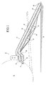
- FIG. 1 is a side view of an evacuation slide incorporating features of the present invention;
- FIG. 2 is a perspective view of the evacuation slide of FIG. 1;
- FIG. 3 is a top plan view of the evacuation slide of FIG. 1.
-
- The drawing figures are intended to illustrate the general manner of construction and are not necessary to scale. In the detailed description and in the figures, specific illustrative examples are shown and herein described in detail. It should be understood, however, that the drawing, the figures, and detailed description are not intended to limit the invention to the particular form disclosed, but are merely illustrative and intended to teach one of ordinary skill how to make and/or use the invention claimed herein and for setting forth the best mode for carrying out the invention.
- FIG. 1 shows an inflatable
evacuation slide system 10 incorporating features of the present invention.Slide system 10 includes aninflatable evacuation slide 12 and aninflator 14 which may be a conventional pyrotechnic, compressed gas, or hybrid inflator well-known in the art. Inflatableevacuation slide system 10 is stored in an undeployed condition in a packboard housing inside the fuselage ofaircraft 16. In a deployed condition,inflatable evacuation slide 12 extends from a location proximal the egress opening 18 ofaircraft 16 toward the ground level 20 or other lower supporting surface. - With reference to FIGs. 1, 2, and 3,
inflatable evacuation slide 12 comprises uppermain support tubes main support tubes surface 30. Flexible slidingsurface 30 is composed of a leftmain panel 32, a rightmain panel 34, afoot end panel 36, a leftupper panel 38, a rightupper panel 40 and ahead end panel 42. Thehead end 44 ofinflatable evacuation slide 12 is secured toaircraft 16 by aconvention girt 46. Uppermain support tubes transverse tube 48 located at thefoot end 50 ofinflatable evacuation slide 12 and an upper head endtransverse tube 52 located athead end 44 ofinflatable evacuation slide 12. Lowermain support tubes transverse tube 54 atfoot end 50 ofinflatable evacuation slide 12 and lower head end transverse tube located athead end 44 ofinflatable evacuation slide 12. Acenter support tube 58 bisects flexible slidingsurface 30 to create two substantially parallel slides. Alateral support tube 60 provides additional support forhead end 44 ofinflatable evacuation slide 12. - With reference to FIGs. 1 and 2, additional support to prevent inflatable evacuation slide from buckling under heavy load is provided by a
lower truss tube 62 and anupper truss tube 64 each of which comprises a U-shaped tube extending from lowermain support tube 24 to lowermain support tube 28. Optionally,lower truss tube 62 andupper truss tube 64 comprise E-shaped tubes interconnecting lower main support totube 24, lowermain support tube 28 andcenter support tube 58. A plurality oftruss straps 66 act as tension members to supportinflatable evacuation slide 12 against buckling under heavy load. - With reference in particular to FIGs. 2 and 3, upper
main support tubes axial center line axial center line head end 44 tofoot end 50 ofinflatable evacuation slide 12, such that thefoot end 50 ofinflatable slide 12 is narrower then thehead end 50. As is well known to structural engineers and bridge designers a trapezoid truss is inherently more rigid to side loading than is a rectangular truss. The inventors of the present invention recognized that similarly, an aircraft evacuation slide that in plan view had main support tubes that tapered together like a trapezoid would provide a substantially more rigid structure than could be achieved with parallel main support tubes. - It is not necessary that a slide constructed in accordance with the teachings of the present invention be a pure trapezoid as long as the
main support tubes - Although certain illustrative embodiments and methods have been disclosed herein, it will be apparent from the foregoing disclosure to those skilled in the art that variations and modifications of such embodiments and methods may be made without departing from the spirit and scope of the invention. Accordingly, it is intended that the invention shall be limited only to extent required by the appended claims and the rules and principals of applicable law.
Claims (8)
- An inflatable escape slide assembly adapted to be extended in a deployed condition from an elevated supporting surface to a lower supporting surface, said inflatable escape slide assembly comprising:said first and second main support tubes each comprising an inflatable tubular member having in a major longitudinal axis, said first and second main support tubes extending from a location proximal the head end of said inflatable escape slide assembly toward the foot end of said inflatable escape slide assembly;a flexible panel defining a slide surface having first and second lateral edges and extending from a head end of said inflatable escape slide assembly to a foot end of said inflatable escape slide assembly;a first main support tube and a second main support tube, said first main support tube being attached to the first lateral edge of said flexible panel and said second main support tube being attached to the second lateral edge of said flexible panel for supporting said flexible panel between said first main support tube and said second main support tube;
said first and second main support tubes being disposed in a spaced-apart configuration with the major longitudinal axes of said first and second main support tubes tapering towards each other in plan view from a widest point proximal the head end of said escape slide assembly to a narrowest point proximal the foot end of said escape slide assembly. - The inflatable escape slide assembly of claim 1, further comprising:a head end transverse tube for maintaining the head end of said first and second main support tubes in said spaced-apart configuration; anda toe end transverse tube for maintaining the foot end of said first and second main support tubes in said spaced-apart configuration, said head end transverse tube being greater in length than said toe end transverse tube.
- The inflatable escape slide assembly of claim 1, wherein:said first and second main support tubes comprised cylindrical tubes of substantially constant circular cross section.
- The inflatable escape slide assembly of claim 1, further comprising:a third main support tube and a fourth main support tube, said third main support tube being disposed below and attached to said first main support tube and said fourth main support tube being disposed below and attached to said second main support tube, said first, second, third and fourth main support tubes cooperating to provide strength and rigidity to said escape slide assembly under load.
- The inflatable escape slide assembly of claim 1, wherein:said first main support tube is longer than said second main support tube such that said escape slide assembly in plan view is canted toward said second main support tube relative to the head end of said escape slide assembly.
- An inflatable escape slide system adapted to extended from an elevated supporting surface to a lower supporting surface, said inflatable escape slide system comprising:said first and second main support tubes each comprising a substantially cylindrical inflatable tubular member having in plan view a longitudinal axis, said first and second main support tubes extending from a location proximal the head end of the inflatable escape slide to a location proximal the foot end of the inflatable escape slide;an inflator for providing a source of pressurized gas; and
an inflatable escape slide pneumatically connected to said inflator;
said inflatable escape slide comprising a flexible panel defining a slide surface having first and second lateral edges and extending from a head end of said inflatable escape slide to a foot end of said inflatable escape slide;
a first main support tube and a second main support tube, said first and second main support tubes being attached to said first and second lateral edges of said flexible panel for supporting said flexible panel;
said first and second main support tubes being disposed in a spaced-apart configuration with the longitudinal axes of said first and second main support tubes tapering towards each other in plan view from a widest point proximal the head end of said escape slide to a narrowest point proximal the foot end of the escape slide. - An inflatable escape slide system adapted to extended from an elevated supporting surface to a lower supporting surface, said inflatable escape slide system comprising:said first and second main support tubes each comprising a substantially cylindrical inflatable tubular member having in plan view a longitudinal axis, said first and second main support tubes extending from a location proximal the head end of the inflatable escape slide to a location proximal the foot end of the inflatable escape slide;an inflator for providing a source of pressurized gas; and
an inflatable escape slide pneumatically connected to said inflator;
said inflatable escape slide comprising a flexible panel defining a slide surface having first and second lateral edges and extending from a head end of said inflatable escape slide to a foot end of said inflatable escape slide;
a first main support tube and a second main support tube, said first and second main support tubes being attached to said first and second lateral edges of said flexible panel for supporting said flexible panel;
said first and second main support tubes being disposed in a spaced-apart configuration with the longitudinal axes of said first and second main support tubes tapering towards each other in plan view from a widest point proximal the head end of said escape slide to a narrowest point proximal the foot end of the escape slide, said first main support tube being greater in length than said second main support tube such that said escape slide assembly in plan view is canted toward said second main support tube relative to the head end of said escape slide assembly. - The inflatable escape slide assembly of claim 7, further comprising:a third main support tube and a fourth main support tube, said third main support tube being disposed below and attached to said first main support tube and said fourth main support tube being disposed below and attached to said second main support tube, said first, second, third and fourth main support tubes cooperating to provide strength and rigidity to said escape slide assembly under load.
Applications Claiming Priority (2)
| Application Number | Priority Date | Filing Date | Title |
|---|---|---|---|
| US177190 | 2002-06-21 | ||
| US10/177,190 US6799741B2 (en) | 2002-06-21 | 2002-06-21 | Evacuation slide having trapezoidal outline |
Publications (2)
| Publication Number | Publication Date |
|---|---|
| EP1375346A2 true EP1375346A2 (en) | 2004-01-02 |
| EP1375346A3 EP1375346A3 (en) | 2005-10-05 |
Family
ID=29717856
Family Applications (1)
| Application Number | Title | Priority Date | Filing Date |
|---|---|---|---|
| EP03007599A Withdrawn EP1375346A3 (en) | 2002-06-21 | 2003-04-02 | Evacuation slide having trapezoidal outline |
Country Status (2)
| Country | Link |
|---|---|
| US (1) | US6799741B2 (en) |
| EP (1) | EP1375346A3 (en) |
Cited By (2)
| Publication number | Priority date | Publication date | Assignee | Title |
|---|---|---|---|---|
| EP3296210A1 (en) * | 2016-09-15 | 2018-03-21 | Goodrich Corporation | Arched inflatable structure for evacuation slide systems |
| RU180275U1 (en) * | 2017-07-21 | 2018-06-07 | Любовь Викторовна Глотова | FIRE RESCUE |
Families Citing this family (19)
| Publication number | Priority date | Publication date | Assignee | Title |
|---|---|---|---|---|
| US6877698B2 (en) * | 2002-07-12 | 2005-04-12 | Universal Propulsion Company, Inc. | Aircraft evacuation slide inflation system using a stored liquified gas capable of thermal decomposition |
| US7494419B2 (en) * | 2006-01-11 | 2009-02-24 | Dov Katz | Indoor stair slide for transporting the handicapped between floors and/or for joyful rides |
| US7467764B2 (en) * | 2006-10-12 | 2008-12-23 | Goodrich Corporation | Fuselage mounted evacuation slide system |
| FR2946615B1 (en) * | 2009-06-12 | 2011-05-27 | Zodiac Solas | INFLATABLE EXHAUST RAMP, AND RESCUE INSTALLATION FOR SHIP, COMPRISING SAME. |
| US9701411B2 (en) * | 2014-12-10 | 2017-07-11 | Airbus Operations Gmbh | Evacuation slide with a guidance marking |
| US9725181B2 (en) | 2015-07-17 | 2017-08-08 | Goodrich Corporation | Off wing evacuation system control strap |
| US10464682B2 (en) * | 2017-01-06 | 2019-11-05 | Goodrich Corporation | Negative lift evacuation slide |
| US10953994B2 (en) * | 2017-09-13 | 2021-03-23 | Goodrich Corporation | Aircraft evacuation system with an integrated spoiler |
| CN108379754B (en) * | 2018-03-01 | 2020-11-13 | 张文清 | Fire control gasbag slide |
| US10822098B2 (en) | 2018-03-23 | 2020-11-03 | Goodrich Corporation | Evacuation system inflatable toe end spring and sill height compensating feature |
| RU183779U1 (en) * | 2018-04-16 | 2018-10-02 | Акционерное общество "Уфимский завод эластомерных материалов, изделий и конструкций" | Inflatable ramp |
| US11130586B2 (en) * | 2019-09-25 | 2021-09-28 | Goodrich Corporation | Lane dividing apparatus |
| US11390391B2 (en) * | 2020-03-19 | 2022-07-19 | Goodrich Corporation | Evacuee-centering evacuation slide |
| USD1033323S1 (en) * | 2020-04-27 | 2024-07-02 | The Boeing Company | Slide for an aircraft |
| US11618578B2 (en) | 2020-04-27 | 2023-04-04 | The Boeing Company | Evacuation slide with markings and lighting for egress from an aircraft |
| US20230227167A1 (en) * | 2022-01-19 | 2023-07-20 | Goodrich Corporation | Parachute and inflatable assembly for air taxi |
| CN115282508A (en) * | 2022-08-02 | 2022-11-04 | 山东商业职业技术学院 | A kind of high-rise building fire rescue equipment |
| US12570377B1 (en) * | 2022-09-28 | 2026-03-10 | The United States Of America As Represented By The Secretary Of The Navy | Afloat structure for launching and recovering vessels |
| USD1125011S1 (en) | 2024-10-11 | 2026-05-05 | The Boeing Company | Evacuation slide for an aircraft |
Citations (3)
| Publication number | Priority date | Publication date | Assignee | Title |
|---|---|---|---|---|
| US3811534A (en) | 1972-07-24 | 1974-05-21 | Goodrich Co B F | Escape slide assembly |
| US5102070A (en) | 1991-06-13 | 1992-04-07 | Air Cruisers Company | Inflatable aircraft evacuation slide arrangement |
| US5820773A (en) | 1997-03-13 | 1998-10-13 | The B. F. Goodrich Company | Escape slide with support tube assembly |
Family Cites Families (8)
| Publication number | Priority date | Publication date | Assignee | Title |
|---|---|---|---|---|
| US3771749A (en) * | 1973-01-05 | 1973-11-13 | Garrett Corp | Emergency aircraft evacuation apparatus and method |
| US3860984A (en) * | 1973-06-25 | 1975-01-21 | Goodrich Co B F | Inflatable life raft escape slide |
| US3973645A (en) * | 1975-08-15 | 1976-08-10 | The Garrett Corporation | Inflatable evacuation slide |
| US4018321A (en) | 1976-05-21 | 1977-04-19 | The B. F. Goodrich Company | Escape slide and platform assembly |
| IT1146172B (en) * | 1979-10-19 | 1986-11-12 | Rfd Inflatables Ltd | IMPROVEMENT IN RESCUE SLIDES |
| US4333546A (en) * | 1980-02-19 | 1982-06-08 | The B. F. Goodrich Company | Escape slide |
| US4684079A (en) * | 1985-12-13 | 1987-08-04 | The Garrett Corporation | Inflatable evacuation device |
| US5875868A (en) * | 1997-02-04 | 1999-03-02 | Air Cruisers Company | Inflatable evacuation slide |
-
2002
- 2002-06-21 US US10/177,190 patent/US6799741B2/en not_active Expired - Lifetime
-
2003
- 2003-04-02 EP EP03007599A patent/EP1375346A3/en not_active Withdrawn
Patent Citations (3)
| Publication number | Priority date | Publication date | Assignee | Title |
|---|---|---|---|---|
| US3811534A (en) | 1972-07-24 | 1974-05-21 | Goodrich Co B F | Escape slide assembly |
| US5102070A (en) | 1991-06-13 | 1992-04-07 | Air Cruisers Company | Inflatable aircraft evacuation slide arrangement |
| US5820773A (en) | 1997-03-13 | 1998-10-13 | The B. F. Goodrich Company | Escape slide with support tube assembly |
Cited By (5)
| Publication number | Priority date | Publication date | Assignee | Title |
|---|---|---|---|---|
| EP3296210A1 (en) * | 2016-09-15 | 2018-03-21 | Goodrich Corporation | Arched inflatable structure for evacuation slide systems |
| CN107826233A (en) * | 2016-09-15 | 2018-03-23 | 古德里奇公司 | Arch inflatable structure for evacuation-slide system |
| US10246195B2 (en) | 2016-09-15 | 2019-04-02 | Goodrich Corporation | Arched inflatable structure for evacuation slide systems |
| CN107826233B (en) * | 2016-09-15 | 2022-05-10 | 古德里奇公司 | Arch-shaped inflatable structure for evacuation slide system |
| RU180275U1 (en) * | 2017-07-21 | 2018-06-07 | Любовь Викторовна Глотова | FIRE RESCUE |
Also Published As
| Publication number | Publication date |
|---|---|
| US20030234323A1 (en) | 2003-12-25 |
| EP1375346A3 (en) | 2005-10-05 |
| US6799741B2 (en) | 2004-10-05 |
Similar Documents
| Publication | Publication Date | Title |
|---|---|---|
| US6799741B2 (en) | Evacuation slide having trapezoidal outline | |
| US5975467A (en) | Inflatable evacuation slide | |
| US4018321A (en) | Escape slide and platform assembly | |
| US3102623A (en) | Escape slide | |
| EP0034358B1 (en) | Escape slide and life raft | |
| US4519782A (en) | Escape slide and life raft | |
| US6536715B1 (en) | Inflatable evacuation slide with arch support | |
| EP3296210B1 (en) | Arched inflatable structure for evacuation slide systems | |
| EP1302399B1 (en) | Passive deployment readiness indicator for aircraft evacuation slide | |
| EP1010617A3 (en) | Overhead accomodations for aircraft | |
| EP3872020A1 (en) | Elevator car | |
| WO1998034823A1 (en) | Aerial cableway leading to an aerostatic airborne body | |
| DE60307627T2 (en) | WATER VEHICLE WITH FAST DEFLECTABLE, HIGH PRESSURE INFLATABLE PLATES | |
| GB2171364A (en) | Inflatable liferaft | |
| US4852690A (en) | Aerial ladder tower with pretensioned truss members | |
| US4112958A (en) | Canopy device | |
| DE60305617T2 (en) | Emergency slide with spoiler at the leading edge | |
| DE1804219A1 (en) | Inflatable life slide | |
| KR101762771B1 (en) | Complex expansion boom for aerial ladder truck | |
| KR20160014555A (en) | Telescopic ladder comprising ladder sections of different densities | |
| US20110198152A1 (en) | Fall arrest assembly | |
| EP1441949B1 (en) | High strength t-joint for inflatable tube structures | |
| DK2181035T3 (en) | TRIANGLE BUILDING EVACUATION SLICES | |
| EP1302400A1 (en) | Evacuation slide with toe end center support member | |
| US6695096B2 (en) | Evacuation slide having toe end transverse support tube |
Legal Events
| Date | Code | Title | Description |
|---|---|---|---|
| PUAI | Public reference made under article 153(3) epc to a published international application that has entered the european phase |
Free format text: ORIGINAL CODE: 0009012 |
|
| AK | Designated contracting states |
Kind code of ref document: A2 Designated state(s): AT BE BG CH CY CZ DE DK EE ES FI FR GB GR HU IE IT LI LU MC NL PT RO SE SI SK TR |
|
| AX | Request for extension of the european patent |
Extension state: AL LT LV MK |
|
| RAP1 | Party data changed (applicant data changed or rights of an application transferred) |
Owner name: GOODRICH CORPORATION |
|
| PUAL | Search report despatched |
Free format text: ORIGINAL CODE: 0009013 |
|
| AK | Designated contracting states |
Kind code of ref document: A3 Designated state(s): AT BE BG CH CY CZ DE DK EE ES FI FR GB GR HU IE IT LI LU MC NL PT RO SE SI SK TR |
|
| AX | Request for extension of the european patent |
Extension state: AL LT LV MK |
|
| 17P | Request for examination filed |
Effective date: 20051223 |
|
| AKX | Designation fees paid |
Designated state(s): DE FR |
|
| STAA | Information on the status of an ep patent application or granted ep patent |
Free format text: STATUS: THE APPLICATION IS DEEMED TO BE WITHDRAWN |
|
| 18D | Application deemed to be withdrawn |
Effective date: 20060725 |