EP1374625B1 - Transmissions in a communication system - Google Patents
Transmissions in a communication system Download PDFInfo
- Publication number
- EP1374625B1 EP1374625B1 EP02733131A EP02733131A EP1374625B1 EP 1374625 B1 EP1374625 B1 EP 1374625B1 EP 02733131 A EP02733131 A EP 02733131A EP 02733131 A EP02733131 A EP 02733131A EP 1374625 B1 EP1374625 B1 EP 1374625B1
- Authority
- EP
- European Patent Office
- Prior art keywords
- base station
- mobile station
- transmissions
- control information
- further control
- Prior art date
- Legal status (The legal status is an assumption and is not a legal conclusion. Google has not performed a legal analysis and makes no representation as to the accuracy of the status listed.)
- Expired - Lifetime
Links
- 230000005540 biological transmission Effects 0.000 title claims abstract description 103
- 238000004891 communication Methods 0.000 title claims description 50
- 238000000034 method Methods 0.000 claims abstract description 45
- 230000004044 response Effects 0.000 claims description 47
- 238000005259 measurement Methods 0.000 claims description 16
- 230000011664 signaling Effects 0.000 description 10
- 230000007246 mechanism Effects 0.000 description 7
- 230000001413 cellular effect Effects 0.000 description 4
- 230000003247 decreasing effect Effects 0.000 description 3
- 208000037918 transfusion-transmitted disease Diseases 0.000 description 3
- 101000633815 Homo sapiens TELO2-interacting protein 1 homolog Proteins 0.000 description 2
- 102100029253 TELO2-interacting protein 1 homolog Human genes 0.000 description 2
- 238000012545 processing Methods 0.000 description 2
- 230000007480 spreading Effects 0.000 description 2
- 230000003044 adaptive effect Effects 0.000 description 1
- 238000013459 approach Methods 0.000 description 1
- 230000003139 buffering effect Effects 0.000 description 1
- 230000010267 cellular communication Effects 0.000 description 1
- 230000008859 change Effects 0.000 description 1
- 230000003111 delayed effect Effects 0.000 description 1
- 230000001419 dependent effect Effects 0.000 description 1
- 238000011161 development Methods 0.000 description 1
- 238000005516 engineering process Methods 0.000 description 1
- 238000005562 fading Methods 0.000 description 1
- 238000012986 modification Methods 0.000 description 1
- 230000004048 modification Effects 0.000 description 1
- 230000008569 process Effects 0.000 description 1
- 230000007727 signaling mechanism Effects 0.000 description 1
Images

Classifications
-
- H—ELECTRICITY
- H04—ELECTRIC COMMUNICATION TECHNIQUE
- H04B—TRANSMISSION
- H04B7/00—Radio transmission systems, i.e. using radiation field
- H04B7/24—Radio transmission systems, i.e. using radiation field for communication between two or more posts
- H04B7/26—Radio transmission systems, i.e. using radiation field for communication between two or more posts at least one of which is mobile
-
- H—ELECTRICITY
- H04—ELECTRIC COMMUNICATION TECHNIQUE
- H04L—TRANSMISSION OF DIGITAL INFORMATION, e.g. TELEGRAPHIC COMMUNICATION
- H04L1/00—Arrangements for detecting or preventing errors in the information received
- H04L1/12—Arrangements for detecting or preventing errors in the information received by using return channel
- H04L1/16—Arrangements for detecting or preventing errors in the information received by using return channel in which the return channel carries supervisory signals, e.g. repetition request signals
- H04L1/1607—Details of the supervisory signal
- H04L1/1692—Physical properties of the supervisory signal, e.g. acknowledgement by energy bursts
-
- H—ELECTRICITY
- H04—ELECTRIC COMMUNICATION TECHNIQUE
- H04W—WIRELESS COMMUNICATION NETWORKS
- H04W52/00—Power management, e.g. TPC [Transmission Power Control], power saving or power classes
- H04W52/04—TPC
- H04W52/38—TPC being performed in particular situations
- H04W52/40—TPC being performed in particular situations during macro-diversity or soft handoff
-
- H—ELECTRICITY
- H04—ELECTRIC COMMUNICATION TECHNIQUE
- H04W—WIRELESS COMMUNICATION NETWORKS
- H04W52/00—Power management, e.g. TPC [Transmission Power Control], power saving or power classes
- H04W52/04—TPC
-
- H—ELECTRICITY
- H04—ELECTRIC COMMUNICATION TECHNIQUE
- H04W—WIRELESS COMMUNICATION NETWORKS
- H04W52/00—Power management, e.g. TPC [Transmission Power Control], power saving or power classes
- H04W52/04—TPC
- H04W52/06—TPC algorithms
- H04W52/14—Separate analysis of uplink or downlink
- H04W52/146—Uplink power control
-
- H—ELECTRICITY
- H04—ELECTRIC COMMUNICATION TECHNIQUE
- H04W—WIRELESS COMMUNICATION NETWORKS
- H04W52/00—Power management, e.g. TPC [Transmission Power Control], power saving or power classes
- H04W52/04—TPC
- H04W52/18—TPC being performed according to specific parameters
- H04W52/22—TPC being performed according to specific parameters taking into account previous information or commands
-
- H—ELECTRICITY
- H04—ELECTRIC COMMUNICATION TECHNIQUE
- H04L—TRANSMISSION OF DIGITAL INFORMATION, e.g. TELEGRAPHIC COMMUNICATION
- H04L1/00—Arrangements for detecting or preventing errors in the information received
- H04L1/12—Arrangements for detecting or preventing errors in the information received by using return channel
- H04L2001/125—Arrangements for preventing errors in the return channel
-
- H—ELECTRICITY
- H04—ELECTRIC COMMUNICATION TECHNIQUE
- H04W—WIRELESS COMMUNICATION NETWORKS
- H04W36/00—Hand-off or reselection arrangements
- H04W36/16—Performing reselection for specific purposes
- H04W36/18—Performing reselection for specific purposes for allowing seamless reselection, e.g. soft reselection
-
- H—ELECTRICITY
- H04—ELECTRIC COMMUNICATION TECHNIQUE
- H04W—WIRELESS COMMUNICATION NETWORKS
- H04W52/00—Power management, e.g. TPC [Transmission Power Control], power saving or power classes
- H04W52/04—TPC
- H04W52/30—TPC using constraints in the total amount of available transmission power
- H04W52/36—TPC using constraints in the total amount of available transmission power with a discrete range or set of values, e.g. step size, ramping or offsets
Definitions
- the present invention relates to a communication system, and in particular, but not exclusively, to transmissions between stations of a communication system.
- Wireless communication media may be provided between a station of a communication network and a user equipment. Wireless communication media may also be provided between two user equipment or between two stations of a communication network.
- a wireless communication systems may be used for various types of communication, such as for voice communication or data communication.
- a wireless system may provide circuit switched or packet switched services or both.
- packet switched services data e.g. speech data, user data, video data or other data
- HSD high speed data
- a cellular communication system An example of wireless communication systems is a cellular communication system.
- the user equipment may access the communication network via access entities referred to as cells, hence the name cellular system.
- the skilled person knows the basic operational principles and elements of a cellular network and these are therefore not explained herein in any greater detail.
- a cell can be defined as an radio access entity that is served by one or several base stations (BS) serving user equipment (UE) via a wireless interface therebetween.
- BS base stations
- UE user equipment
- Examples of the cellular networks include networks that are based on access systems such as the CDMA (Code Division Multiple Access), WCDMA (Wide-band CDMA), TDMA (Time Division Multiple Access), FDMA (Frequency Division Multiple Access), or SDMA (Space Division Multiple Access) and hybrids thereof.
- CDMA Code Division Multiple Access
- WCDMA Wide-band CDMA
- TDMA Time Division Multiple Access
- FDMA Frequency Division Multiple Access
- SDMA Space Division Multiple Access
- a wireless communication system is typically provided with a radio resource management function.
- a feature of the radio resource management is that it may continuously adjust the use of resources such as the power levels between a base (transceiver) station and user equipment associated with said base station during communication between the base station and the user equipment.
- Use of radio resources may be controlled for transmissions that occur from the base station towards the user equipment (downlink) and from the user equipment towards the base station (uplink). The adjustment is done in order to provide a sufficient quality and reliability for the transmission between the base station and the user equipment in various conditions and, on the other hand, to reduce power consumption and interference caused by the communication to other devices.
- a user equipment may communication simultaneously with a number of base stations.
- Figure 1 shows an example where a user equipment MS1 is in communication with two base stations BS1, BS2.
- the simultaneous communication with a plurality of base stations may occur, for example, when a user equipment is to be handed over from a base station to another base station.
- the handover may be performed by means of the so called soft handover procedure.
- the CDMA soft handover may be used to reduce the interference caused by the user equipment.
- the transmission power of a user equipment is typically adjusted based on power control commands from a base station that request for the lowest transmission power.
- Each base station involved in the soft handover measures the quality of the signal from a given user equipment and sends its power control commands to the user equipment asking the power up or down.
- the user equipment increases its transmission power only if all base stations involved in the soft handover request for more power.
- the user equipment may receive data such as control messages, user data and so on from a base station.
- the user equipment may receive data from more than one base station. Some of these data transmissions may need to be responded by the user equipment.
- the response may, for example, be an acknowledgement that the user equipment did receive the message and/or that the user equipment did accomplish a task in response to the message and/or a response to an inquiry and/or any other feedback that may be required by the base station.
- 3G WCDMA third generation wideband code division multiple access
- the above referred high speed data may be enabled e.g. by means of the so called high speed downlink packet access (HSDPA) technology.
- the high speed downlink packet access (HSDPA) may include functions such as fast hybrid automatic repeat request (HARQ), adaptive coding and modulation (AMC) and/or fast cell selection (FCS). These functions are known by the skilled person and will thus not be explained in more detail.
- HARQ fast hybrid automatic repeat request
- AMC adaptive coding and modulation
- FCS fast cell selection
- each user equipment receiving data on a high speed downlink shared channel also has an associated dedicated channel (DCH) allocated.
- the dedicated channel may be mapped to a dedicated physical channel (DPCH) in the physical layer.
- the DPCH is typically divided into dedicated physical data channel (PPDCH) and dedicated physical control channel (DPCCH) both in the uplink and the downlink.
- Data such as the power control commands, transport format information, and dedicated pilot symbols are transmitted on the DPCCH.
- Information such as diversity feedback information may also be transmitted on DPCCH in the uplink.
- the HS-DSCH may be mapped to one or several high speed physical downlink shared channels (HS-PDSCH) in the physical layer.
- the associated dedicated channel is typically provided both in the downlink and the uplink.
- the dedicated channel is typically used to carry HSDPA related information/signalling as well as other dedicated data such as speech and control data.
- the user equipment may communicate with several base stations at the same time.
- the associated dedicated channel may be in soft handover.
- the HS-DSCH may be associated also with a shared control channel (SCCH).
- SCCH shared control channel
- the SCCH can be used to carry HS-DSCH specific information/signalling to those users receiving data on the HS-DSCH.
- a current proposal is to use the dedicated channel to inform the user equipment that it has data to be read on the HS-DSCH and SCCH. That is, only those users receiving data at a given time will receive an indication on the dedicated channel.
- the dedicated channel may be called as a pointer channel since it points to the shared channels.
- the dedicated channel may also contain information about modulation and coding schemes, power levels and similar parameters used for the shared channels. This information can be sent also on the shared channel.
- the shared control channel on the other hand is used to carry information that is specific to the data transmitted on the shared data channel (HS-DSCH). This information can contain for instance packet numbers for the HARQ and so on.
- the shared control channel can be sent on a separate code channel (code multiplexed) or using the same code channels as HS-PDSCH (time multiplexed).
- the HS-DSCH is assumed not to be in soft handover. That is, each base station is assumed to have their own shared channel and the user equipment is assumed to receive data from only one base station at a time.
- FCS fast cell selection
- the shared channels does not use power control. Instead, the shared channels are proposed to be transmitted with fixed or semi-fixed power.
- the term 'semi-fixed' means in here that the power is not changed often. The power could, for instance, be a cell specific parameter.
- the high speed downlink shared channel (HS-DSCH) is planned to be associated with a dedicated channel which would carry in the downlink at least information regarding the timing when the receiving station is to receive on a shared channel.
- the associated dedicated channel may possibly carry also other information.
- the associated dedicated channel may carry, for example, the required acknowledgements (ACK) for a fast HARQ.
- a problematic situation may occur especially when the associated dedicated channel is in the soft handover mode.
- the uplink power is adjusted in accordance with the best quality uplink among an active set of base stations.
- signalling on the high speed shared channel may be transmitted from another base station.
- the communication link between the user equipment and said other base station may be of poorer quality than said best uplink connection.
- said other base station expects to receive responses such as an acknowledgement from the user equipment. Since the quality of this uplink connection may be of substantially poorer quality than what the best uplink is, there is a risk that the response is not properly received and decoded or is not received at all.
- the fast cell selection function may be used to guarantee in some occasions that best possible downlink is utilised for communication towards the user equipment.
- the base station that provides the best uplink may be different than the base station providing the best downlink. This may be so, for example due to fast fading or other changes in the signalling conditions. This may increase the unreliability of the responding functionality.
- the prior art proposals for solving this problem include so called strong coding, e.g., by using repetition coding.
- the acknowledgement (ACK) bit or bits is/are repeated several times. This, however, may cause too much additional load on the air interface and/or reserve too much of the radio resources if one wants to guarantee the correct reception of the acknowledgement message.
- Embodiments of the present invention aim to address one or several of the above problems.
- the present invention provides a device according to claim 16, for communication with a first station; and apparatus according to claim 31 for use in a system in which a device is in communication with a first station; a method according to claim 1 of operating a device in communication with a first station; and a method of according to claim 46 for use in a system in which a device is in communication with a first station.
- the exemplifying communication system comprises a radio access part adapted to operate based on the WCDMA (Wideband Code Division Multiple Access) technique.
- WCDMA Wideband Code Division Multiple Access
- a feature of the WCDMA based systems is that a plurality of user equipment is allowed to communicate with a base transceiver station in a cell over a radio interface (only one user equipment, however, is shown in Figure 1 for clarity).
- a user equipment 1 is also allowed to be in radio communication with more than one base station at the same time.
- Figure 1 shows only two base stations 11, 12 for clarity.
- the user equipment comprises a mobile station 1.
- the term mobile station refers to a mobile user equipment that is enabled to move from a location to another.
- a mobile station may also roam from one network to another network, if the other network is compatible with the standard the given mobile station is adapted to and there is a roaming agreement between the operators of the two networks.
- Each of the base stations 11, 12 may be provided with a controller entity BCE.
- the controller entity may be adapted to perform various task, such as to measure and control power levels that are used for communication between the base station and the mobile station 1.
- the operation of the base station may also be controlled by at least one further controller entity, such as a radio network controller NC.
- the arrangement is typically such the various control functions associated with a base station are divided between the controller entity of the base station and a network controller entity.
- a network controller entity may be adapted to control one or several base stations.
- the various network controller entities may be connected to each other for communication therebetween.
- Communication between the mobile station and the base stations may comprise any kind of data such as speech data, video data or other data.
- the base stations and mobile station communicate also control data.
- the control data may associate with management operations.
- the control data may comprise messages such as various request and acknowledgements.
- Data may be transmitted between the stations as a plurality of data symbols in subsequent data or radio frames.
- the signals carrying the data may be transmitted with variable data symbol transmission rates (data speeds), wherein the transmission rate may be different in subsequent frames of the transmission.
- the data symbols may be transmitted based on different access techniques. For example, in the CDMA (Code Division Multiple Access) system data is encoded for transmission by processing data symbols to be transmitted by a spreading code for each transmission channel. In the TDMA (Time Division Multiple Access) system data is transmitted in different time slots allocated for different channels.
- CDMA Code Division Multiple Access
- TDMA Time Division Multiple Access
- the communication between the mobile station 1 and the base stations 11 and 12 may occur via different communication channels, such as via a dedicated channel, shared channel and so on.
- the channels may be distinguished from one another by the use of scrambling codes in a manner which is known by the skilled person.
- FIG 1 the different signalling conditions between the mobile station and the base stations are illustrated by different widths of the arrows between the stations.
- base station 11 has a weaker uplink with the mobile station MS1 than the other base station 12. This implies that the power control of the uplink follows the base station 12.
- the downlink from base station 11 may be stronger than what the downlink from the base station 12 is.
- Each of the base stations of Figure 1 may be enabled to measure one or more parameter that associate with the connection.
- the parameter may be a quality parameter such as the power levels or signal to interference (SIR) level in the uplink. That is, the power level or SIR level at which each base station 11, 12 receives from the mobile station 1 may be known by the respective base station.
- SIR signal to interference
- the power control mechanism in the access network is typically such that the mobile station 1 follows the power commands received from the "strongest" base station, e.g. the base station 12 that receives the signal transmitted by 1 with the best quality parameter.
- the transmission power of the mobile station 1 is then adjusted accordingly even if the other base station 11 keeps on asking for more transmission power. This is so since the mobile station 1 only increases transmission power if all those base stations that are in soft handover with the mobile station MS1 ask for more power.
- the mobile station 1 adjusts it transmission power based on the power commands received from the base station 12.
- the power adjustment mechanism may be based on use of the so called quality target or power threshold values. If the quality of the connection is below the target value, the mobile station 1 is asked to increase the transmission power and if the quality is above the target, the power is asked to be decreased.
- connection quality target can be announced e.g. by means of so called Eb/No (Signal Energy/Noise) or SIR (Signal to Interference Ratio) or desired signal level target or a similar parameter indicating a quality measure which can be estimated for the connection between two stations.
- Eb/No Synchronization Energy/Noise
- SIR Synchronization to Interference Ratio
- the quality of the connection is controlled based on the target value. Any of the connection parameters that have influence to the quality of the connection should follow any changes in the target. In most cases it is sufficient if the transmission power is increased/decreased in order to meet the quality target value.
- a more detailed description of a possible closed loop power control mechanism can be found, for example, from 3GPP (third generation partnership project) technical specification No. TS25.214 "Physical layer procedures (FDD)".
- the CDMA systems may include also an outer loop power control mechanism. This may adjust the power or SIR target based on other quality target parameters such as the bit error rate (BER) or frame error rate (FER) or any other similar quality target the connection should meet.
- BER bit error rate
- FER frame error rate
- a first station may transmit data or a request or an enquiry to a second station. After reception of said transmission the second station then transmits a response back to the first station.
- information associated with at least one parameter for the response is signalled from the first station to the second station. This parameter may, for example, associate with the required power levels of the response and/or the number of times the response shall be transmitted and so on. The response signalling is then performed based on the received information.
- the first station is the base station BS1 and the second station is the mobile station MS1.
- the base station 11 allocates a channel to the mobile station MS1 and sends data thereto on the high speed data shared channel (HS-DSCH)
- the base station 11 expects the mobile station to return an acknowledgement (ACK).
- HS-DSCH high speed data shared channel
- the base station 11 may provide the mobile station with information on an associated control channel (either dedicated or shared) regarding the power levels required for the response.
- the information provides the mobile station 1 with an offset value.
- the offset value indicates the difference in power relative to power level used for transmission in the best uplink with the base station 12.
- the base station 11 determines the offset that is needed for the reliable acknowledgement transmission from the mobile station 1 based on one or more measurements associated with transmissions from the mobile station. The power is determined such that a predefined level of reliability is obtained for the decoding of the acknowledgement at the base station 11.
- the mobile station 1 is provided with appropriate power control entity PC.
- a per se known power control entity can be adapted to incorporate a feature that enables adjustment of the response transmission power levels based on the information received from the base station 11. That is, the power control entity of the mobile station may make a decision that the response transmission needs to be accomplished in a different power level than what is used for communication with the best base station 12 and control the transmission accordingly.
- the acknowledgement message may be transmitted back to the base station 11 on a dedicated channel.
- the dedicated channel may be 'on' all the time even if there is no acknowledgements to be sent. This is so in order to keep the closed loop power control running.
- the active base station 11 may measure a quality parameter such as the signal to interference ratio (SIR) of this dedicated channel for overall power control purposes. This may be done e.g. based on so called pilot bits that are transmitted by the mobile station.
- SIR signal to interference ratio
- the base station 11 can calculate a required power offset.
- the power offset requirement is signalled from the base station 11 to the mobile station 1 with the downlink data packet to tell the mobile 1 how much more power is required for the acknowledgement transmission.
- New signalling bits may be added in the downlink transmission from the base station 11 to tell the required power offset for the user equipment 1. These bits may be sent, e.g., on the shared control channel since only the user equipment or those user equipment receiving on the downlink shared data channel need to send the acknowledgement ACK. That is, this information is not needed all the time, but only when there is data packets to acknowledge. Alternatively, the base station may sent these bits to the user equipment via a dedicated control channel or dedicated data channel.
- the power control may be accomplished in a slot by slot basis in access techniques wherein the transmissions occur in slots.
- a transmission can be divided into the slots e.g. based on time or by means of a spreading code.
- the mobile station MS1 may be adapted to assign power for the slots in accordance with a "normal" power control mechanism unless the mobile station has been provided with information which requires use of a different power level for a slot (or several slots) that are allocated for the response.
- '0' could indicate that an offset of 5dB is required and '1' could indicate an offset of 10dB. According to another possibility '0' could indicate that no offset is required and '1' could indicate that a predefined additional power is required.
- 2 to 4 bits may be used in a typical application for defining 4 to 16 different power offset levels.
- a step between the different power levels may be, for example, 2, 5 or 10 dB.
- the step size between the power levels may be adapted to change nonlinearly.
- Figure 3 shows transmission of data packets between a base station (node B) and two user equipment UE1 and UE2.
- base station node B
- UE1 and UE2 user equipment
- Figure 3 shows channels in association with only one base station, a plurality of base stations may have communication channels with the user equipment UE1 and/or UE2 at the same time. Other channels are, however, not shown for reasons of clarity.
- a number of packets is shown to be transmitted to a first user equipment UE1 and to a second user equipment UE2 on the data channel HSPDSCH.
- the vertical lines of Figure 3 dividing the transmission into sections indicate a high speed downlink packet access transmission time intervals (HSDPA TTI).
- the HSDPA TTI is a collection of a defined number of slots. That is, the high speed downlink packet access transmission time interval (TTI) defines a period for data transportation between user equipment and a base station via the high speed downlink shared channel (HSDSCH). Logically the TTI can thus be seen to correspond the concept of data frames.
- TTI high speed downlink packet access transmission time interval
- HSDSCH high speed downlink shared channel
- acknowledgements are provided in accordance with the fast hybrid automatic repeat request (HARQ) scheme.
- a so called N-channel HARQ is also assumed to be used for the fast HARQ together with a so called stop-and-wait protocol.
- the stop-and-wait protocol may be used in order to reduce buffering requirements of the receiving station.
- the N-channel HARQ supports asynchronous transmission. Thus different users can be scheduled freely without need to wait for completion of a given transmission.
- the receiving station may need, however, to know to which HARQ process the packet belongs to. This information can be explicitly signalled on a high speed downlink packet access (HSDPA) control channel (CH), e.g. the SCCH.
- HSDPA high speed downlink packet access
- CH control channel
- the transmission to the first user equipment UE1 may in such case be delayed by two TTIs.
- the processing times of data packet to different user equipment should be defined such that continuous transmission to a user equipment is possible.
- Each packet is preferably acknowledged during the transmission of other packets so that the downlink (DL) channel can be kept occupied all the time when there are packets to be transmitted.
- DL downlink
- FIG 3 the uplink acknowledgements are shown to be transmitted on the dedicated physical control channel (DPCCH).
- Arrows R1 to R9 indicate various relations between different operations. That is, relations between pointer bits on the DL DPCH, shared data and control channel (HS-PDSCH and SCCH) transmission and the acknowledgement transmissions.
- each of the double lined arrows R2, R5 and R9 indicates a quality measurement performed for the uplink of a given user equipment on the respective dedicated control channel.
- the single lined arrows R1, R4 and R8 indicate the relationships between the pointer bits and shared control channel SCCH in the downlink.
- the single lined arrows R3 and R6 indicate the relationships between the downlink data channel HSPDSCH and acknowledgements in the uplink. The acknowledgements are transmitted with a power that has been adjusted based on information received on the SCCH, that is based on the results of the measurements.
- the base station transmits a pointer bit to the user equipment UE1.
- the pointer bit indicates that the user equipment UE1 shall receive data and control information during the next TTI (TTI2) on the HS-PDSCH and on the SCCH.
- TTI2 next TTI
- the base station measures the quality of the uplink of the user equipment UE1.
- the SIR of the uplink can be measured from the dedicated pilot symbols transmitted on the DPCCH in every slot. Based on this quality measurement, the base station provides the user equipment UE1 in the TTI2 with information regarding the power level that should be used when transmitting the acknowledgement during TTI4. This relation is indicated by arrow R3.
- the power level information can be provided as a power offset, as explained above. This power offset information may be, for example, provided as a field of a few bits in the shared control channel (SCCH).
- the measurements may be averaged over a longer period of time or otherwise processed.
- the arrow R2 simply shows that the power offset used for the transmission is based on the measurement(s) done before the transmission of the power offset.
- the user equipment UE1 After having received the power level information the user equipment UE1 sends the acknowledgement using a power level that is based on information from the base station.
- the acknowledgement may be a positive acknowledgement (A in Figure 3 ) or a negative acknowledgement (N in Figure 3 ).
- acknowledgement slots are shown to be higher in order to illustrate that increased transmit power is used for these acknowledgements.
- the increased power may be applied for the whole slot or only on the acknowledgement bits within the slot.
- the same increased power may also be used in other slots if they contain other information such as measurement or quality report which is sent only to the same base station as the acknowledgement.
- the increased power may also be applied to the entire TTI or even a number of TTIs.
- Figure 3 illustrates also a second set of relations R4 to R9 that associate with the user equipment UE2.
- the acknowledgement was negative (N) and therefore a new pointer bit was given on the DL CPCH channel of the second user equipment UE2 for retransmission of the message.
- the uplink quality measurement is preferably accomplished as late as possible.
- information associated e.g. with the measurement as indicated by the arrow R2 is transmitted in the next transmission time interval (TTI2) on the control channel (DLSCCH).
- the embodiments are especially suitable for acknowledgements because the acknowledgements need to be sent in response to a downlink transmission and also because the reliability of the acknowledgement transmission should be high.
- the message specific control information may be signalled only when the first station determines that a different parameter is needed in order to ensure a reliable response by the user equipment.
- each base station in connection may continuously measure the quality of the uplink.
- each of the base stations may send power offset information to the user equipment telling how much the power should be changed (increased or decreased) in order to meet the quality target. This information is preferably sent on the dedicated control channel.
- the user equipment may follow the normal power control commands. However, when the user equipment has something to send to one base station only, the user equipment may then use the power offset sent by that base station.
- the offset may be sent periodically, e.g., in each slot as the power control commands, or once per every n slots and so on.
- the offset information may also be sent when needed, e.g., when the value of the offset exceeds some threshold values.
- the user equipment may also be forced to use stronger coding for the transmission of the acknowledgement message.
- the user equipment may be instructed to transmit the acknowledgement repeatedly. For example, instead of sending the acknowledgement once the user equipment may be instructed to transmit the acknowledgement three, five, or ten times and so on.
- the user equipment is instructed to transmit the acknowledgement e.g. in three slots instead of one slot so that the acknowledgement can be decoded reliably.
- the above discussed transmission parameter information provision mechanism may also be used in connection with other signalling functions than acknowledgements.
- the response messages could be, for example, measurement reports or other reports.
- the herein proposed signalling mechanism may be especially advantageous if a report is requested by a base station of a plurality of base stations in communication with a user equipment.
- the base station may inform the user equipment of the power offset and/or any other parameter that is to be used for the response towards the specific base station.
- the adjustment may also be based on other information that associates with the interface between the two stations.
- the base station 11 may request for a certain power offset based on analysis of the previous responses from the mobile station 1. If the analysis indicates that a certain number of responses has not been correct, the offset may be increased in order to improve the reliability.
- the responses may be earlier ACKs or other data transmitted from the user equipment, e.g., speech packets.
- the above disclosed solution is applicable also in instances where the first message is sent from the user equipment to a base station.
- the user equipment may inform the base station of any requirements that it may have for the response from the base station.
- a first station transmitting a message that is to be responded by a second station may insert in the message information regarding e.g. coding and/or power that is to be used for responding to the particular packet.
- the response may also be sent, for example, on a shared control channel or a data channel in systems where such a channel is defined.
- a specific acknowledgement channel may also be defined.
- the data is described as being in packet form. In alternative embodiments of the invention the data may be sent in any suitable format.
- the measurement may be accomplished and/or information transmitted e.g. in predefined intervals or in response to a predefined event (e.g. the quality of the connection has changed or the user equipment has been relocated from a network controller to another network controller and so on). It may thus be enough if the offset information is provided once for the user equipment during a connection between the user equipment and a base station.
- the embodiment of the present invention has been described in the context of a CDMA system. This invention is also applicable to any other access techniques including time division multiple access, frequency division multiple access or space division multiple access as well as any hybrids thereof.
- the base station may in some communication standards, such as those associated with the 3 rd generation (3G) universal mobile telecommunications system (UMTS), be referred to as node B.
- 3G 3 rd generation
- UMTS universal mobile telecommunications system
- a dedicated physical channel is used only in association with a high speed downlink shared channel (HS-DSCH). That is, no other data is transmitted on the DPDCH.
- the power control of the DPCH may then follow base station that transmits on the active HS-DSCH (both in the uplink and the downlink) instead of the best base station. If no other data is transported on the uplink DPDCH, then the uplink power control function of the mobile station could follow the active high speed data base station. In such a situation information regarding the power offset may not be needed for the uplink, since the power control function may adjust the power.
Abstract
Description
- The present invention relates to a communication system, and in particular, but not exclusively, to transmissions between stations of a communication system.
- Various different communication systems adapted to provide wireless communication between two or more stations are known. Wireless communication media may be provided between a station of a communication network and a user equipment. Wireless communication media may also be provided between two user equipment or between two stations of a communication network.
- A wireless communication systems may be used for various types of communication, such as for voice communication or data communication. A wireless system may provide circuit switched or packet switched services or both. In packet switched services data (e.g. speech data, user data, video data or other data) is communicated in data packets. The development in the wireless communication has lead to systems that are capable of transporting data in substantially high data rates i.e. the so called high speed data (HSD).
- An example of wireless communication systems is a cellular communication system. In a cellular system the user equipment may access the communication network via access entities referred to as cells, hence the name cellular system. The skilled person knows the basic operational principles and elements of a cellular network and these are therefore not explained herein in any greater detail. It is sufficient to note that a cell can be defined as an radio access entity that is served by one or several base stations (BS) serving user equipment (UE) via a wireless interface therebetween. Examples of the cellular networks include networks that are based on access systems such as the CDMA (Code Division Multiple Access), WCDMA (Wide-band CDMA), TDMA (Time Division Multiple Access), FDMA (Frequency Division Multiple Access), or SDMA (Space Division Multiple Access) and hybrids thereof.
- A wireless communication system is typically provided with a radio resource management function. A feature of the radio resource management is that it may continuously adjust the use of resources such as the power levels between a base (transceiver) station and user equipment associated with said base station during communication between the base station and the user equipment. Use of radio resources may be controlled for transmissions that occur from the base station towards the user equipment (downlink) and from the user equipment towards the base station (uplink). The adjustment is done in order to provide a sufficient quality and reliability for the transmission between the base station and the user equipment in various conditions and, on the other hand, to reduce power consumption and interference caused by the communication to other devices.
- A user equipment may communication simultaneously with a number of base stations.
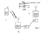
Figure 1 shows an example where a user equipment MS1 is in communication with two base stations BS1, BS2. The simultaneous communication with a plurality of base stations may occur, for example, when a user equipment is to be handed over from a base station to another base station. - The handover may be performed by means of the so called soft handover procedure. For example, in the CDMA soft handover may be used to reduce the interference caused by the user equipment. During a soft handover the transmission power of a user equipment is typically adjusted based on power control commands from a base station that request for the lowest transmission power. Each base station involved in the soft handover measures the quality of the signal from a given user equipment and sends its power control commands to the user equipment asking the power up or down. The user equipment increases its transmission power only if all base stations involved in the soft handover request for more power.
- The user equipment may receive data such as control messages, user data and so on from a base station. The user equipment may receive data from more than one base station. Some of these data transmissions may need to be responded by the user equipment. The response may, for example, be an acknowledgement that the user equipment did receive the message and/or that the user equipment did accomplish a task in response to the message and/or a response to an inquiry and/or any other feedback that may be required by the base station. The following will discuss a more detailed example that relates to acknowledgements in a third generation wideband code division multiple access (3G WCDMA) system.
- In WCDMA based systems the above referred high speed data may be enabled e.g. by means of the so called high speed downlink packet access (HSDPA) technology. The high speed downlink packet access (HSDPA) may include functions such as fast hybrid automatic repeat request (HARQ), adaptive coding and modulation (AMC) and/or fast cell selection (FCS). These functions are known by the skilled person and will thus not be explained in more detail. A more detailed description of these and other function of the HSPDA can be found e.g. from a third generation partnership project technical report No. 3G TR25.848 release 2000 titled 'Physical Layer Aspects of UTRA High Speed Downlink Packet Access'. It shall be appreciated that although the HSDPA has been specified for use in the WCDMA, similar basic principles may be applied to other access techniques.
- At the present it is assumed that in the high speed downlink packet access (HSDPA) each user equipment receiving data on a high speed downlink shared channel (HS-DSCH) also has an associated dedicated channel (DCH) allocated. The dedicated channel may be mapped to a dedicated physical channel (DPCH) in the physical layer. The DPCH is typically divided into dedicated physical data channel (PPDCH) and dedicated physical control channel (DPCCH) both in the uplink and the downlink. Data such as the power control commands, transport format information, and dedicated pilot symbols are transmitted on the DPCCH. Information such as diversity feedback information may also be transmitted on DPCCH in the uplink. The HS-DSCH may be mapped to one or several high speed physical downlink shared channels (HS-PDSCH) in the physical layer.
- The associated dedicated channel is typically provided both in the downlink and the uplink. The dedicated channel is typically used to carry HSDPA related information/signalling as well as other dedicated data such as speech and control data. The user equipment may communicate with several base stations at the same time. For example, the associated dedicated channel may be in soft handover.
- In addition to associated dedicated channels, the HS-DSCH may be associated also with a shared control channel (SCCH). The SCCH can be used to carry HS-DSCH specific information/signalling to those users receiving data on the HS-DSCH.
- A current proposal is to use the dedicated channel to inform the user equipment that it has data to be read on the HS-DSCH and SCCH. That is, only those users receiving data at a given time will receive an indication on the dedicated channel. The dedicated channel may be called as a pointer channel since it points to the shared channels. The dedicated channel may also contain information about modulation and coding schemes, power levels and similar parameters used for the shared channels. This information can be sent also on the shared channel. The shared control channel on the other hand is used to carry information that is specific to the data transmitted on the shared data channel (HS-DSCH). This information can contain for instance packet numbers for the HARQ and so on. The shared control channel can be sent on a separate code channel (code multiplexed) or using the same code channels as HS-PDSCH (time multiplexed).
- Unlike the dedicated channel, the HS-DSCH is assumed not to be in soft handover. That is, each base station is assumed to have their own shared channel and the user equipment is assumed to receive data from only one base station at a time. The so called fast cell selection (FCS) technique may be used to switch the data transmission from one base station to another. However, the shared channels does not use power control. Instead, the shared channels are proposed to be transmitted with fixed or semi-fixed power. The term 'semi-fixed' means in here that the power is not changed often. The power could, for instance, be a cell specific parameter.
- In the currently proposed arrangements the high speed downlink shared channel (HS-DSCH) is planned to be associated with a dedicated channel which would carry in the downlink at least information regarding the timing when the receiving station is to receive on a shared channel. The associated dedicated channel may possibly carry also other information. In the uplink, the associated dedicated channel may carry, for example, the required acknowledgements (ACK) for a fast HARQ.
- The inventor has found that this may be problematic for example in the context of the uplink power control of the fast HARQ acknowledgements. A problematic situation may occur especially when the associated dedicated channel is in the soft handover mode. During the soft handover the uplink power is adjusted in accordance with the best quality uplink among an active set of base stations. However, signalling on the high speed shared channel may be transmitted from another base station. The communication link between the user equipment and said other base station may be of poorer quality than said best uplink connection. Nevertheless, said other base station expects to receive responses such as an acknowledgement from the user equipment. Since the quality of this uplink connection may be of substantially poorer quality than what the best uplink is, there is a risk that the response is not properly received and decoded or is not received at all.
- The fast cell selection function may be used to guarantee in some occasions that best possible downlink is utilised for communication towards the user equipment. However, the base station that provides the best uplink may be different than the base station providing the best downlink. This may be so, for example due to fast fading or other changes in the signalling conditions. This may increase the unreliability of the responding functionality.
- The prior art proposals for solving this problem include so called strong coding, e.g., by using repetition coding. In the repetition coding the acknowledgement (ACK) bit or bits is/are repeated several times. This, however, may cause too much additional load on the air interface and/or reserve too much of the radio resources if one wants to guarantee the correct reception of the acknowledgement message.
- Another prior art proposal is the so called fixed power offset for acknowledgement (ACK) transmissions. This means that all acknowledgement messages are transmitted with increased or a certain power in order to ensure that the acknowledgement is received even through the poorest quality uplink. However, even a fixed power level for acknowledgement messages may not completely solve the problem of substantially poor signalling conditions. Thus situations where the power is not high enough may still occur. On the other hand, it is also possible that the fixed power level is unnecessarily high. Thus, in addition to reliability problems this approach may be disadvantageous in that too high power is used by the user equipment causing interference and unnecessarily high power consumption.
WO08/56120 US 6173162 andWO98/36508 - Embodiments of the present invention aim to address one or several of the above problems.
- The present invention provides a device according to claim 16, for communication with a first station; and apparatus according to claim 31 for use in a system in which a device is in communication with a first station; a method according to
claim 1 of operating a device in communication with a first station; and a method of according to claim 46 for use in a system in which a device is in communication with a first station. - Embodiments of the invention are defined in the dependent claims.
- For better understanding of the present invention, reference will now be made by way of example to the accompanying drawings in which:
-
Figure 1 shows an access system wherein the present invention may be embodied; -
Figure 2 is a flowchart illustrating the operation of an embodiment of the present invention; and -
Figure 3 shows a specific embodiment. - An embodiment will now be described with reference to a mobile telecommunication system. The exemplifying communication system comprises a radio access part adapted to operate based on the WCDMA (Wideband Code Division Multiple Access) technique. A feature of the WCDMA based systems is that a plurality of user equipment is allowed to communicate with a base transceiver station in a cell over a radio interface (only one user equipment, however, is shown in
Figure 1 for clarity). As shown byFigure 1 , auser equipment 1 is also allowed to be in radio communication with more than one base station at the same time.Figure 1 shows only twobase stations 11, 12 for clarity. - The user equipment comprises a
mobile station 1. The term mobile station refers to a mobile user equipment that is enabled to move from a location to another. A mobile station may also roam from one network to another network, if the other network is compatible with the standard the given mobile station is adapted to and there is a roaming agreement between the operators of the two networks. - Each of the
base stations 11, 12 may be provided with a controller entity BCE. The controller entity may be adapted to perform various task, such as to measure and control power levels that are used for communication between the base station and themobile station 1. In addition to the controller entity of the base station, the operation of the base station may also be controlled by at least one further controller entity, such as a radio network controller NC. The arrangement is typically such the various control functions associated with a base station are divided between the controller entity of the base station and a network controller entity. A network controller entity may be adapted to control one or several base stations. The various network controller entities may be connected to each other for communication therebetween. - Communication between the mobile station and the base stations may comprise any kind of data such as speech data, video data or other data. The base stations and mobile station communicate also control data. The control data may associate with management operations. The control data may comprise messages such as various request and acknowledgements.
- Data may be transmitted between the stations as a plurality of data symbols in subsequent data or radio frames. The signals carrying the data may be transmitted with variable data symbol transmission rates (data speeds), wherein the transmission rate may be different in subsequent frames of the transmission. The data symbols may be transmitted based on different access techniques. For example, in the CDMA (Code Division Multiple Access) system data is encoded for transmission by processing data symbols to be transmitted by a spreading code for each transmission channel. In the TDMA (Time Division Multiple Access) system data is transmitted in different time slots allocated for different channels.
- The communication between the
mobile station 1 and thebase stations 11 and 12 may occur via different communication channels, such as via a dedicated channel, shared channel and so on. In some systems such as the CDMA the channels may be distinguished from one another by the use of scrambling codes in a manner which is known by the skilled person. - In
Figure 1 the different signalling conditions between the mobile station and the base stations are illustrated by different widths of the arrows between the stations. As shown, base station 11 has a weaker uplink with the mobile station MS1 than theother base station 12. This implies that the power control of the uplink follows thebase station 12. However, as shown inFigure 1 , the downlink from base station 11 may be stronger than what the downlink from thebase station 12 is. - Each of the base stations of
Figure 1 may be enabled to measure one or more parameter that associate with the connection. The parameter may be a quality parameter such as the power levels or signal to interference (SIR) level in the uplink. That is, the power level or SIR level at which eachbase station 11, 12 receives from themobile station 1 may be known by the respective base station. - The power control mechanism in the access network is typically such that the
mobile station 1 follows the power commands received from the "strongest" base station, e.g. thebase station 12 that receives the signal transmitted by 1 with the best quality parameter. The transmission power of themobile station 1 is then adjusted accordingly even if the other base station 11 keeps on asking for more transmission power. This is so since themobile station 1 only increases transmission power if all those base stations that are in soft handover with the mobile station MS1 ask for more power. - In the following example it is assumed that in normal operation the
mobile station 1 adjusts it transmission power based on the power commands received from thebase station 12. The power adjustment mechanism may be based on use of the so called quality target or power threshold values. If the quality of the connection is below the target value, themobile station 1 is asked to increase the transmission power and if the quality is above the target, the power is asked to be decreased. - The connection quality target can be announced e.g. by means of so called Eb/No (Signal Energy/Noise) or SIR (Signal to Interference Ratio) or desired signal level target or a similar parameter indicating a quality measure which can be estimated for the connection between two stations.
- The quality of the connection is controlled based on the target value. Any of the connection parameters that have influence to the quality of the connection should follow any changes in the target. In most cases it is sufficient if the transmission power is increased/decreased in order to meet the quality target value. A more detailed description of a possible closed loop power control mechanism can be found, for example, from 3GPP (third generation partnership project) technical specification No. TS25.214 "Physical layer procedures (FDD)".
- In addition to the closed loop power control mechanism the CDMA systems may include also an outer loop power control mechanism. This may adjust the power or SIR target based on other quality target parameters such as the bit error rate (BER) or frame error rate (FER) or any other similar quality target the connection should meet.
- In the embodiments a first station may transmit data or a request or an enquiry to a second station. After reception of said transmission the second station then transmits a response back to the first station. To improve the reliability and/or optimise the use of resources, information associated with at least one parameter for the response is signalled from the first station to the second station. This parameter may, for example, associate with the required power levels of the response and/or the number of times the response shall be transmitted and so on. The response signalling is then performed based on the received information.
- In the
Figure 1 example the first station is the base station BS1 and the second station is the mobile station MS1. For example, when the base station 11 allocates a channel to the mobile station MS1 and sends data thereto on the high speed data shared channel (HS-DSCH), the base station 11 expects the mobile station to return an acknowledgement (ACK). - The base station 11 may provide the mobile station with information on an associated control channel (either dedicated or shared) regarding the power levels required for the response. In a preferred embodiment the information provides the
mobile station 1 with an offset value. The offset value indicates the difference in power relative to power level used for transmission in the best uplink with thebase station 12. The base station 11 determines the offset that is needed for the reliable acknowledgement transmission from themobile station 1 based on one or more measurements associated with transmissions from the mobile station. The power is determined such that a predefined level of reliability is obtained for the decoding of the acknowledgement at the base station 11. - The
mobile station 1 is provided with appropriate power control entity PC. A per se known power control entity can be adapted to incorporate a feature that enables adjustment of the response transmission power levels based on the information received from the base station 11. That is, the power control entity of the mobile station may make a decision that the response transmission needs to be accomplished in a different power level than what is used for communication with thebest base station 12 and control the transmission accordingly. - The acknowledgement message (ACK) may be transmitted back to the base station 11 on a dedicated channel. The dedicated channel may be 'on' all the time even if there is no acknowledgements to be sent. This is so in order to keep the closed loop power control running. The active base station 11 may measure a quality parameter such as the signal to interference ratio (SIR) of this dedicated channel for overall power control purposes. This may be done e.g. based on so called pilot bits that are transmitted by the mobile station. Thus the base station 11 can calculate a required power offset. The power offset requirement is signalled from the base station 11 to the
mobile station 1 with the downlink data packet to tell the mobile 1 how much more power is required for the acknowledgement transmission. - New signalling bits may be added in the downlink transmission from the base station 11 to tell the required power offset for the
user equipment 1. These bits may be sent, e.g., on the shared control channel since only the user equipment or those user equipment receiving on the downlink shared data channel need to send the acknowledgement ACK. That is, this information is not needed all the time, but only when there is data packets to acknowledge. Alternatively, the base station may sent these bits to the user equipment via a dedicated control channel or dedicated data channel. - The power control may be accomplished in a slot by slot basis in access techniques wherein the transmissions occur in slots. A transmission can be divided into the slots e.g. based on time or by means of a spreading code. The mobile station MS1 may be adapted to assign power for the slots in accordance with a "normal" power control mechanism unless the mobile station has been provided with information which requires use of a different power level for a slot (or several slots) that are allocated for the response.
- In a simple case one bit may be enough for the provision of the above referenced information. For example, '0' could indicate that an offset of 5dB is required and '1' could indicate an offset of 10dB. According to another possibility '0' could indicate that no offset is required and '1' could indicate that a predefined additional power is required.
- 2 to 4 bits may be used in a typical application for defining 4 to 16 different power offset levels. A step between the different power levels may be, for example, 2, 5 or 10 dB. Alternatively the step size between the power levels may be adapted to change nonlinearly.
- A more specific embodiment will now be described with reference to
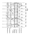
Figure 3 showing transmission of data packets between a base station (node B) and two user equipment UE1 and UE2. It shall be appreciated that althoughFigure 3 shows channels in association with only one base station, a plurality of base stations may have communication channels with the user equipment UE1 and/or UE2 at the same time. Other channels are, however, not shown for reasons of clarity. - A number of packets is shown to be transmitted to a first user equipment UE1 and to a second user equipment UE2 on the data channel HSPDSCH. The vertical lines of
Figure 3 dividing the transmission into sections indicate a high speed downlink packet access transmission time intervals (HSDPA TTI). The HSDPA TTI is a collection of a defined number of slots. That is, the high speed downlink packet access transmission time interval (TTI) defines a period for data transportation between user equipment and a base station via the high speed downlink shared channel (HSDSCH). Logically the TTI can thus be seen to correspond the concept of data frames. In theFigure 3 example eight TTIs are shown, each TTI being three slots in length. - In the following it is assumed that the acknowledgements are provided in accordance with the fast hybrid automatic repeat request (HARQ) scheme. A so called N-channel HARQ is also assumed to be used for the fast HARQ together with a so called stop-and-wait protocol. The stop-and-wait protocol may be used in order to reduce buffering requirements of the receiving station.
- The N-channel HARQ supports asynchronous transmission. Thus different users can be scheduled freely without need to wait for completion of a given transmission. The receiving station may need, however, to know to which HARQ process the packet belongs to. This information can be explicitly signalled on a high speed downlink packet access (HSDPA) control channel (CH), e.g. the SCCH. For example, after three packets have been transported to the first user equipment UE1, two packets may be transmitted to the second user equipment UE2. The transmission to the first user equipment UE1 may in such case be delayed by two TTIs. The processing times of data packet to different user equipment should be defined such that continuous transmission to a user equipment is possible.
- Each packet is preferably acknowledged during the transmission of other packets so that the downlink (DL) channel can be kept occupied all the time when there are packets to be transmitted.
- In
Figure 3 the uplink acknowledgements are shown to be transmitted on the dedicated physical control channel (DPCCH). Arrows R1 to R9 indicate various relations between different operations. That is, relations between pointer bits on the DL DPCH, shared data and control channel (HS-PDSCH and SCCH) transmission and the acknowledgement transmissions. - More particularly, each of the double lined arrows R2, R5 and R9 indicates a quality measurement performed for the uplink of a given user equipment on the respective dedicated control channel. The single lined arrows R1, R4 and R8 indicate the relationships between the pointer bits and shared control channel SCCH in the downlink. The single lined arrows R3 and R6 indicate the relationships between the downlink data channel HSPDSCH and acknowledgements in the uplink. The acknowledgements are transmitted with a power that has been adjusted based on information received on the SCCH, that is based on the results of the measurements.
- During the first interval TTI1 the base station transmits a pointer bit to the user equipment UE1. The pointer bit indicates that the user equipment UE1 shall receive data and control information during the next TTI (TTI2) on the HS-PDSCH and on the SCCH. Also during TTI1, the base station measures the quality of the uplink of the user equipment UE1. These relations are shown by the relation arrows R1 and R2, respectively.
- For example, the SIR of the uplink can be measured from the dedicated pilot symbols transmitted on the DPCCH in every slot. Based on this quality measurement, the base station provides the user equipment UE1 in the TTI2 with information regarding the power level that should be used when transmitting the acknowledgement during TTI4. This relation is indicated by arrow R3. The power level information can be provided as a power offset, as explained above. This power offset information may be, for example, provided as a field of a few bits in the shared control channel (SCCH).
- It should be noted that the measurements may be averaged over a longer period of time or otherwise processed. The arrow R2 simply shows that the power offset used for the transmission is based on the measurement(s) done before the transmission of the power offset.
- After having received the power level information the user equipment UE1 sends the acknowledgement using a power level that is based on information from the base station. The acknowledgement may be a positive acknowledgement (A in
Figure 3 ) or a negative acknowledgement (N inFigure 3 ). - In
Figure 3 , some of the acknowledgement slots are shown to be higher in order to illustrate that increased transmit power is used for these acknowledgements. The increased power may be applied for the whole slot or only on the acknowledgement bits within the slot. The same increased power may also be used in other slots if they contain other information such as measurement or quality report which is sent only to the same base station as the acknowledgement. The increased power may also be applied to the entire TTI or even a number of TTIs. - In addition to relations R1 to R3,
Figure 3 illustrates also a second set of relations R4 to R9 that associate with the user equipment UE2. In this case the acknowledgement was negative (N) and therefore a new pointer bit was given on the DL CPCH channel of the second user equipment UE2 for retransmission of the message. - In order to ensure that the power level for the response can be determined appropriately by the base station the uplink quality measurement is preferably accomplished as late as possible. As shown, information associated e.g. with the measurement as indicated by the arrow R2 is transmitted in the next transmission time interval (TTI2) on the control channel (DLSCCH).
- The embodiments are especially suitable for acknowledgements because the acknowledgements need to be sent in response to a downlink transmission and also because the reliability of the acknowledgement transmission should be high.
- The message specific control information may be signalled only when the first station determines that a different parameter is needed in order to ensure a reliable response by the user equipment.
- In a further embodiment each base station in connection (for instance, in a soft handover) with the user equipment may continuously measure the quality of the uplink. In addition to the normal power control commands each of the base stations may send power offset information to the user equipment telling how much the power should be changed (increased or decreased) in order to meet the quality target. This information is preferably sent on the dedicated control channel. In a normal soft handover case the user equipment may follow the normal power control commands. However, when the user equipment has something to send to one base station only, the user equipment may then use the power offset sent by that base station. The offset may be sent periodically, e.g., in each slot as the power control commands, or once per every n slots and so on. The offset information may also be sent when needed, e.g., when the value of the offset exceeds some threshold values.
- In an embodiment the user equipment may also be forced to use stronger coding for the transmission of the acknowledgement message. For example, the user equipment may be instructed to transmit the acknowledgement repeatedly. For example, instead of sending the acknowledgement once the user equipment may be instructed to transmit the acknowledgement three, five, or ten times and so on. According to an embodiment the user equipment is instructed to transmit the acknowledgement e.g. in three slots instead of one slot so that the acknowledgement can be decoded reliably.
- The above discussed transmission parameter information provision mechanism may also be used in connection with other signalling functions than acknowledgements. The response messages could be, for example, measurement reports or other reports. The herein proposed signalling mechanism may be especially advantageous if a report is requested by a base station of a plurality of base stations in communication with a user equipment. The base station may inform the user equipment of the power offset and/or any other parameter that is to be used for the response towards the specific base station.
- The above discussed adjustment of at least one feature of the response signalling based on information from power level measurements. The adjustment may also be based on other information that associates with the interface between the two stations. For example, the base station 11 may request for a certain power offset based on analysis of the previous responses from the
mobile station 1. If the analysis indicates that a certain number of responses has not been correct, the offset may be increased in order to improve the reliability. The responses may be earlier ACKs or other data transmitted from the user equipment, e.g., speech packets. - It is noted that the above disclosed solution is applicable also in instances where the first message is sent from the user equipment to a base station. In such a case the user equipment may inform the base station of any requirements that it may have for the response from the base station.
- It shall be appreciated that whilst embodiments of the present invention have been described in relation to mobile stations, embodiments of the present invention are applicable to any other suitable type of user equipment.
- It shall be appreciated that whilst embodiments of the present invention have been described in relation to a mobile station that is in communication with more than one base station, the present invention is applicable also to instances where only two station are in communication with each other. For example, a first station transmitting a message that is to be responded by a second station may insert in the message information regarding e.g. coding and/or power that is to be used for responding to the particular packet.
- It shall be appreciated that while this specification mentions some system specific examples of the communication channels the embodiments of the invention are not restricted by these examples.
- The response may also be sent, for example, on a shared control channel or a data channel in systems where such a channel is defined. A specific acknowledgement channel may also be defined.
- The data is described as being in packet form. In alternative embodiments of the invention the data may be sent in any suitable format.
- In addition, it is not always necessary to measure the quality of the connection for each data packet and/or to provide the user equipment with the offset information each time a response is required. Instead, the measurement may be accomplished and/or information transmitted e.g. in predefined intervals or in response to a predefined event (e.g. the quality of the connection has changed or the user equipment has been relocated from a network controller to another network controller and so on). It may thus be enough if the offset information is provided once for the user equipment during a connection between the user equipment and a base station.
- The embodiment of the present invention has been described in the context of a CDMA system. This invention is also applicable to any other access techniques including time division multiple access, frequency division multiple access or space division multiple access as well as any hybrids thereof.
- It shall be appreciated that the base station may in some communication standards, such as those associated with the 3rd generation (3G) universal mobile telecommunications system (UMTS), be referred to as node B. However, this specification has used the term base station for clarity.
- According to an alternative solution for the above discussed problem a dedicated physical channel (DPCH) is used only in association with a high speed downlink shared channel (HS-DSCH). That is, no other data is transmitted on the DPDCH. The power control of the DPCH may then follow base station that transmits on the active HS-DSCH (both in the uplink and the downlink) instead of the best base station. If no other data is transported on the uplink DPDCH, then the uplink power control function of the mobile station could follow the active high speed data base station. In such a situation information regarding the power offset may not be needed for the uplink, since the power control function may adjust the power.
- It is also noted herein that while the above describes exemplifying embodiments of the invention, there are several variations and modifications which may be made to the disclosed solution without departing from the scope of the present invention as defined in the appended claims.
Claims (60)
- A method for use at a mobile station comprising:receiving at a mobile station (1) in communication with at least a first base station (11) via a wireless interface power control commands from said first base station and each of any other base stations (12) with which the mobile station is also in simultaneous communication;and characterised by comprising:receiving at said mobile station further control information associated with a transmission parameter for use by said mobile station for one or more transmissions to said first base station; andcontrolling one or more transmissions from said mobile station to said first base station on the basis of a power control command from the base station that receives transmissions from said mobile station with the best quality parameter, and on the basis of said further control information, wherein the further control information comprises a control command selected from a plurality of control commands.
- A method according to claim 1, wherein the further control information includes power offset information regarding how much more transmission power is to be used for one or more transmissions from said mobile station to said first base station.
- A method according to claim 2, wherein the power offset information indicates whether no offset is required or whether a predefined additional power is required.
- A method according to claim 2, wherein the power offset information indicates whether an offset of a first value is required or whether an offset of a second value is required.
- A method according to claim 1, wherein the further control information specifies the use of stronger coding for said one or more transmissions from said mobile station to said first base station.
- A method according to claim 1, wherein the further control information includes an instruction to repeat the said one or more transmissions to said first base station an increased number of times.
- A method according to any of claims 1 to 6, wherein said one or more transmissions from said mobile station to said first base station include an acknowledgement of data received at said mobile station from said first base station.
- A method according to claim 7, wherein the one or more transmissions from said mobile station to said first base station include an acknowledgement of data received from said first base station on a high speed data shared channel (HS-DSCH).
- A method according to claim 1 wherein said one or more transmissions from said mobile station to said first base station include a measurement report or a quality report.
- A method according to any of claims 1 to 9 wherein the further control information is sent in response to a predefined event.
- A method according to any of claims 1 to 10 wherein the further control information is provided once for the mobile station during a connection between the mobile station and a base station.
- A method according to any of claims 1 to 9, wherein the one or more transmissions to said first base station include responses to messages from the first base station, and wherein said further control information is provided each time a response is required.
- A method according to claim 12, wherein the further control information is inserted in each message to which a response is required.
- A method according to claim 12 or claim 13 wherein the messages from the first base station are provided on a data channel, and wherein the further control information is provided on an associated control channel.
- A method according to any of claims 1 to 9, wherein the one or more transmissions to said first base station include responses to messages from the first base station on a data channel, and wherein said further control information is provided on a control channel associated with said data channel.
- Apparatus for use at a mobile station (1), which apparatus is configured to:receive power control commands from a first base station (11) with which said mobile station is in communication via a wireless interface and also from any other base stations (12) with which said mobile station is also in simultaneous communication;and which is characterised by being configured to:receive further control information associated with a transmission parameter for use by the mobile station for one or more transmissions to said first base station; andcontrol one or more transmissions from said mobile station to said first base station on the basis of a power control command from the base station that receives transmissions from said mobile station with the best quality parameter, and on the basis of said further control information , wherein the further control information comprises a control command selected from a plurality of control commands.
- Apparatus according to claim 16, wherein the further control information includes power offset information regarding how much more transmission power is to be used for one or more transmissions from said mobile station to said first base station.
- Apparatus according to claim 17, wherein the power offset information indicates whether no offset is required or whether a predefined additional power is required.
- Apparatus according to claim 17, wherein the power offset information indicates whether an offset of a first value is required or whether an offset of a second value is required.
- Apparatus according to claim 16, wherein the further control information specifies the use of stronger coding for said one or more transmissions from said mobile station to said first base station.
- Apparatus according to claim 16, wherein the further control information includes an instruction to repeat the said one or more transmissions to said first base station an increased number of times.
- Apparatus according to any of claims 16 to 21, wherein said one or more transmissions from said mobile station to said first base station include an acknowledgement of data received at said mobile station from said first base station.
- Apparatus according to claim 22, wherein the one or more transmissions from said mobile station to said first base station include an acknowledgement of data received from said first base station on a high speed data shared channel (HS-DSCH).
- Apparatus according to claim 16 wherein said one or more transmissions from said mobile station to said first base station include a measurement report or a quality report.
- Apparatus according to any of claims 16 to 24 wherein the further control information is sent in response to a predefined event.
- Apparatus according to any of claims 16 to 25 wherein the further control information is provided once for the mobile station during a connection between the mobile station and a base station.
- Apparatus according to any of claims 16 to 24, wherein the one or more transmissions to said first base station include responses to messages from the first base station, and wherein said further control information is provided each time a response is required.
- Apparatus according to claim 27, wherein the further control information is inserted in each message to which a response is required.
- Apparatus according to claim 27 or claim 28 wherein the meesages from the first base station are provided on a data channel, and wherein the further control information is provided on an associated control channel.
- Apparatus according to any of claims 16 to 24, wherein the one or more transmissions to said first base station include responses to messages from the first base station on a data channel, and wherein said further control information is provided on a control channel associated with said data channel.
- Apparatus for use in a system in which a mobile station is in communication with at least a first base station via a wireless interface and receives power control commands from said first base station and each of any other base stations with which the mobile station is also in simultaneous communication; wherein the apparatus is characterised in that it is configured to provide the mobile station with further control information associated with a transmission parameter for use by said mobile station for one or more transmissions to said first base station; wherein the further control information comprises a control command selected from a plurality of control commands by the apparatus, and is used by the mobile station together with a power control command from the base station that receives transmissions from said mobile station with the best quality parameter to control one or more transmissions from said mobile station to said first base station.
- Apparatus according to claim 31, wherein the further control information includes power offset information regarding how much more transmission power is to be used for one or more transmissions from said mobile station to said first base station.
- Apparatus according to claim 32, wherein the power offset information indicates whether no offset is required or whether a predefined additional power is required.
- Apparatus according to claim 32, wherein the power offset information indicates whether an offset of a first value is required or whether an offset of a second value is required.
- Apparatus according to claim 31, wherein the further control information specifies the use of stronger coding for said one or more transmissions from said mobile station to said first base station.
- Apparatus according to claim 31, wherein the further control information includes an instruction to repeat the said one or more transmissions to said first base station an increased number of times.
- Apparatus according to any of claims 31 to 36, wherein said one or more transmissions from said mobile station to said first base station include an acknowledgement of data received at said mobile station from said first base station.
- Apparatus according to claim 37, wherein the one or more transmissions from said mobile station to said first base station include an acknowledgement of data received from said first base station on a high speed data shared channel (HS-DSCH).
- Apparatus according to claim 31 wherein said one or more transmissions from said mobile station to said first base station include a measurement report or a quality report.
- Apparatus according to any of claims 31 to 39 wherein the further control information is sent in response to a predefined event.
- Apparatus according to any of claims 31 to 40 wherein the further control information is provided once for the mobile station during a connection between the mobile station and a base station.
- Apparatus according to any of claims 31 to 39, wherein the one or more transmissions to said first base station include responses to messages from the first base station, and wherein said further control information is provided each time a response is required.
- Apparatus according to claim 42, wherein the further control information is inserted in each message to which a response is required.
- Apparatus according to claim 42 or claim 43 wherein the messages from the first base station are provided on a data channel, and wherein the further control information is provided on an associated control channel.
- Apparatus according to any of claims 31 to 39, wherein the one or more transmissions to said first base station include responses to messages from the first base station on a data channel, and wherein said further control information is provided on a control channel associated with said data channel.
- A method for use in a system in which a mobile station is in communication with at least a first base station via a wireless interface and receives power control commands from said first base station and each of any other base stations with which the mobile station is also in simultaneous communication; wherein the method is characterised by: providing the mobile station with further control information associated with a transmission parameter for use by said mobile station for one or more transmissions to said first base station; wherein the further control information comprises a control command selected from a plurality of control commands, and is used by the mobile station together with a power control command from the base station that receives transmissions from said mobile station with the best quality parameter to control one or more transmissions from said mobile station to said first base station.
- A method according to claim 46, wherein the further control information includes power offset information regarding how much more transmission power is to be used for one or more transmissions from said mobile station to said first base station.
- A method according to claim 47, wherein the power offset information indicates whether no offset is required or whether a predefined additional power is required.
- A method according to claim 47, wherein the power offset information indicates whether an offset of a first value is required or whether an offset of a second value is required.
- A method according to claim 46, wherein the further control information specifies the use of stronger coding for said one or more transmissions from said mobile station to said first base station.
- A method according to claim 46, wherein the further control information includes an instruction to repeat the said one or more transmissions to said first base station an increased number of times.
- A method according to any of claims 46 to 51, wherein said one or more transmissions from said mobile station to said first base station include an acknowledgement of data received at said mobile station from said first base station.
- A method according to claim 52, wherein the one or more transmissions from said mobilie station to said first base station include an acknowledgement of data received from said first base station on a high speed data shared channel (HS-DSCH).
- A method according to claim 46 wherein said one or more transmissions from said mobile station to said first base station include a measurement report or a quality report.
- A method according to any of claims 46 to 54 wherein the further control information is sent in response to a predefined event.
- A method according to any of claims 46 to 55 wherein the further control information is provided once for the mobile station during a connection between the mobile station and a base station.
- A method according to any of claims 46 to 54, wherein the one or more transmissions to said first base station include responses to messages from the first base station, and wherein said further control information is provided each time a response is required.
- A method according to claim 57, wherein the further control information is inserted in each message to which a response is required.
- A method according to claim 57 or claim 58 wherein the messages from the first base station are provided on a data channel, and wherein the further control information is provided on an associated control channel.
- A method according to any of claims 46 to 54, wherein the one or more transmissions to said first base station include responses to messages from the first base station on a data channel, and wherein said further control information is provided on a control channel associated with said data channel.
Priority Applications (1)
| Application Number | Priority Date | Filing Date | Title |
|---|---|---|---|
| EP09163501.1A EP2110977B1 (en) | 2001-03-28 | 2002-03-28 | Uplink control channel transmission method and apparatus therefor |
Applications Claiming Priority (3)
| Application Number | Priority Date | Filing Date | Title |
|---|---|---|---|
| GBGB0107746.0A GB0107746D0 (en) | 2001-03-28 | 2001-03-28 | Transmissions in a communication system |
| GB0107746 | 2001-03-28 | ||
| PCT/IB2002/002035 WO2002082666A2 (en) | 2001-03-28 | 2002-03-28 | Transmissions in a communication system |
Related Child Applications (1)
| Application Number | Title | Priority Date | Filing Date |
|---|---|---|---|
| EP09163501.1A Division EP2110977B1 (en) | 2001-03-28 | 2002-03-28 | Uplink control channel transmission method and apparatus therefor |
Publications (2)
| Publication Number | Publication Date |
|---|---|
| EP1374625A2 EP1374625A2 (en) | 2004-01-02 |
| EP1374625B1 true EP1374625B1 (en) | 2009-08-05 |
Family
ID=9911741
Family Applications (2)
| Application Number | Title | Priority Date | Filing Date |
|---|---|---|---|
| EP02733131A Expired - Lifetime EP1374625B1 (en) | 2001-03-28 | 2002-03-28 | Transmissions in a communication system |
| EP09163501.1A Expired - Lifetime EP2110977B1 (en) | 2001-03-28 | 2002-03-28 | Uplink control channel transmission method and apparatus therefor |
Family Applications After (1)
| Application Number | Title | Priority Date | Filing Date |
|---|---|---|---|
| EP09163501.1A Expired - Lifetime EP2110977B1 (en) | 2001-03-28 | 2002-03-28 | Uplink control channel transmission method and apparatus therefor |
Country Status (14)
| Country | Link |
|---|---|
| US (3) | US7496374B2 (en) |
| EP (2) | EP1374625B1 (en) |
| JP (2) | JP4292010B2 (en) |
| KR (1) | KR100616648B1 (en) |
| CN (1) | CN1251550C (en) |
| AT (1) | ATE439020T1 (en) |
| AU (1) | AU2002304333B2 (en) |
| BR (2) | BR0208472A (en) |
| CA (1) | CA2442142C (en) |
| DE (1) | DE60233210D1 (en) |
| GB (1) | GB0107746D0 (en) |
| MX (1) | MXPA03008854A (en) |
| RU (1) | RU2292647C2 (en) |
| WO (1) | WO2002082666A2 (en) |
Families Citing this family (55)
| Publication number | Priority date | Publication date | Assignee | Title |
|---|---|---|---|---|
| GB0107746D0 (en) * | 2001-03-28 | 2001-05-16 | Nokia Networks Oy | Transmissions in a communication system |
| KR100811043B1 (en) * | 2001-11-16 | 2008-03-06 | 엘지전자 주식회사 | method for controlling transmission power of SCH and HI in mobile communication |
| KR100832117B1 (en) | 2002-02-17 | 2008-05-27 | 삼성전자주식회사 | Apparatus for transmitting/receiving uplink power offset in communication system using high speed downlink packet access scheme |
| US7508804B2 (en) * | 2002-04-05 | 2009-03-24 | Alcatel-Lucent Usa Inc. | Shared signaling for multiple user equipment |
| JP4213117B2 (en) * | 2002-05-10 | 2009-01-21 | 三菱電機株式会社 | Mobile communication system, base station, mobile station, and communication method |
| WO2004028098A1 (en) * | 2002-09-06 | 2004-04-01 | Fujitsu Limited | Radio network control apparatus |
| KR100722066B1 (en) * | 2003-02-12 | 2007-05-25 | 마츠시타 덴끼 산교 가부시키가이샤 | Receiving apparatus and receiving method |
| CN103220767B (en) | 2003-03-26 | 2017-04-12 | 美商内数位科技公司 | Node B, a radio network controller and a method of providing HSDPA services performed thereby |
| SE0301076D0 (en) * | 2003-04-08 | 2003-04-08 | Ericsson Telefon Ab L M | A method in a telecommunication system |
| US7146171B2 (en) * | 2003-05-30 | 2006-12-05 | Nokia Corporation | Method and apparatus providing enhanced reservation access mode for a CDMA reverse channel |
| JP4482293B2 (en) | 2003-07-03 | 2010-06-16 | パナソニック株式会社 | Base station apparatus and transmission method |
| KR20130093154A (en) | 2003-07-16 | 2013-08-21 | 인터디지탈 테크날러지 코포레이션 | Method and system for transferring information between network management entities of a wireless communication system |
| US6958982B2 (en) | 2003-07-16 | 2005-10-25 | Interdigital Technology Corporation | Method and apparatus for storing mobile station physical measurements and MAC performance statistics in a management information base of an access point |
| JP4623978B2 (en) * | 2004-02-18 | 2011-02-02 | 日本電気株式会社 | Mobile communication system, communication control method therefor, radio network controller and base station used therefor |
| EP1587256A1 (en) * | 2004-04-15 | 2005-10-19 | Siemens Aktiengesellschaft | Method for data transmission in a radio communication system |
| US7724722B2 (en) | 2004-07-01 | 2010-05-25 | Samsung Electronics Co., Ltd. | System and method for transmitting uplink control information in an OFDMA communication system |
| US8897828B2 (en) | 2004-08-12 | 2014-11-25 | Intellectual Ventures Holding 81 Llc | Power control in a wireless communication system |
| WO2007004628A1 (en) * | 2005-07-06 | 2007-01-11 | Nec Corporation | Mobile communication system using portable terminal and handover control method |
| CN1921333B (en) * | 2005-08-24 | 2010-11-24 | 大唐移动通信设备有限公司 | Power control method for physical channel transmitting binary reduplicate information bit |
| US8817737B2 (en) | 2005-10-31 | 2014-08-26 | Lg Electronics Inc. | Method of transmitting and receiving data in a mobile communication network |
| CN101292446A (en) | 2005-10-31 | 2008-10-22 | Lg电子株式会社 | Method of transmitting a measurement report in a wireless mobile communications system |
| WO2007052916A1 (en) | 2005-10-31 | 2007-05-10 | Lg Electronics Inc. | Method for processing control information in a wireless mobile communication system |
| EP1949562B1 (en) | 2005-10-31 | 2016-11-16 | LG Electronics Inc. | Method of transmitting a measurement report in a wireless mobile communications system |
| US8830945B2 (en) | 2005-10-31 | 2014-09-09 | Lg Electronics Inc. | Method for processing control information in a wireless mobile communication system |
| JP4708982B2 (en) * | 2005-11-02 | 2011-06-22 | 株式会社エヌ・ティ・ティ・ドコモ | Retransmission control method and receiving apparatus |
| ATE438246T1 (en) * | 2005-11-28 | 2009-08-15 | Telecom Italia Spa | METHOD AND SYSTEM FOR SENDING CONTENT TO MULTIPLE USERS OF A MOBILE COMMUNICATIONS NETWORK |
| US7996032B2 (en) * | 2006-03-27 | 2011-08-09 | Qualcomm Incorporated | Power control and resource management in orthogonal wireless systems |
| EP1853079B1 (en) * | 2006-05-03 | 2013-01-09 | Nokia Siemens Networks GmbH & Co. KG | Radio resource administration in a mobile radio communications network |
| US8238319B2 (en) * | 2006-09-01 | 2012-08-07 | Advanced Telecommunications Research Institute International | Radio apparatus |
| US8699968B2 (en) * | 2007-03-14 | 2014-04-15 | Google Inc. | Using multiple and a single feedback for UE uplink beamforming in soft handoff |
| KR101162425B1 (en) | 2007-04-30 | 2012-07-11 | 인터디지탈 테크날러지 코포레이션 | Handling cell reselections and transitions to and from an enhanced cell fach state |
| US8830905B2 (en) * | 2007-08-14 | 2014-09-09 | Ntt Docomo, Inc. | Base station apparatus, mobile station apparatus, and communications control method |
| US9467923B2 (en) * | 2008-02-07 | 2016-10-11 | Broadcom Corporation | Method and system for location-based prearranged hand-off |
| US11477721B2 (en) | 2008-02-22 | 2022-10-18 | Qualcomm Incorporated | Methods and apparatus for controlling transmission of a base station |
| US8199719B2 (en) | 2008-03-13 | 2012-06-12 | Apple Inc. | Methods and apparatus for performing handover between a long term evolution (LTE) network and another type of radio access network |
| JP5109856B2 (en) * | 2008-07-30 | 2012-12-26 | 富士通株式会社 | Radio mobile station apparatus and radio base station apparatus |
| KR101589600B1 (en) | 2008-08-05 | 2016-01-28 | 삼성전자주식회사 | Method and apparatus for transmitting and receiving uplink acknowledgement channel for downlink data channel in mobile communication systems using orthogonal frequency division multiple access |
| JP5297889B2 (en) * | 2009-05-21 | 2013-09-25 | シャープ株式会社 | Wireless communication system and wireless communication apparatus |
| JP4982528B2 (en) * | 2009-06-12 | 2012-07-25 | パナソニック株式会社 | Base station apparatus, mobile station apparatus, and transmission method |
| WO2011043720A1 (en) | 2009-10-09 | 2011-04-14 | Telefonaktiebolaget L M Ericsson (Publ) | Methods and devices for uplink diversity transmission |
| WO2011070733A1 (en) * | 2009-12-08 | 2011-06-16 | 日本電気株式会社 | Wireless communication system, base station device, base station control device, transmission power control method for a base station, and computer-readable medium |
| US8868091B2 (en) * | 2010-01-18 | 2014-10-21 | Qualcomm Incorporated | Methods and apparatus for facilitating inter-cell interference coordination via over the air load indicator and relative narrowband transmit power |
| KR101142052B1 (en) | 2010-02-18 | 2012-07-19 | 한미약품 주식회사 | Method of preparing zanamivir |
| EP2362563B1 (en) | 2010-02-23 | 2016-01-06 | Alcatel Lucent | Channel state information feedback |
| US8370690B1 (en) * | 2010-04-28 | 2013-02-05 | Sprint Communications Company L.P. | Custom defined call quality versus battery life |
| CN103069738B (en) | 2010-07-15 | 2016-01-20 | Lg电子株式会社 | The method and apparatus of subscriber equipment transmission and reception confirmation response in wireless communication system |
| KR101759940B1 (en) | 2010-11-03 | 2017-07-21 | 엘지전자 주식회사 | Method for Controlling Uplink Transmission Power in a Broadband Wireless Access System |
| US8965444B2 (en) | 2011-02-09 | 2015-02-24 | Qualcomm Incorporated | Adjusting a signal-to-interference ratio target based on a signal characteristic |
| EP2777336B1 (en) * | 2011-11-09 | 2015-10-07 | Telefonaktiebolaget L M Ericsson (publ) | Base station, user equipment, radio network controller and methods therein |
| EP2807860A4 (en) * | 2012-01-23 | 2016-04-13 | Intel Corp | Network assisted user association and offloading techniques for integrated multi-rat heterogeneous networks |
| US8817695B1 (en) * | 2012-05-03 | 2014-08-26 | Sprint Spectrum L.P. | Dynamic adjustment of reverse link ACK transmission power based on forward link slot utilization |
| US9596658B2 (en) * | 2012-05-31 | 2017-03-14 | Mediatek Inc. | Power control methods |
| WO2014140907A2 (en) * | 2013-03-15 | 2014-09-18 | Powerwave Technologies S.A.R.L. | Downlink power management |
| KR101915063B1 (en) * | 2014-03-28 | 2018-11-15 | 후지츠 코네쿠텟도 테크노로지즈 가부시키가이샤 | Wireless communication system, base station, terminal, and processing method |
| CN111800242B (en) * | 2019-08-09 | 2022-02-22 | 维沃移动通信有限公司 | Feedback information transmission method, device, equipment and medium |
Family Cites Families (40)
| Publication number | Priority date | Publication date | Assignee | Title |
|---|---|---|---|---|
| GB0107746D0 (en) * | 2001-03-28 | 2001-05-16 | Nokia Networks Oy | Transmissions in a communication system |
| US5267262A (en) | 1989-11-07 | 1993-11-30 | Qualcomm Incorporated | Transmitter power control system |
| US5507018A (en) | 1991-03-06 | 1996-04-09 | Nokia Telecommunications Oy | Method and a device for controlling a radio transmitter |
| ATE162035T1 (en) | 1991-06-03 | 1998-01-15 | British Telecomm | RADIO SYSTEM |
| SE9200915D0 (en) * | 1992-03-24 | 1992-03-24 | Ericsson Telefon Ab L M | METHODS IN A CELLULAR MOBILE RADIO COMMUNINCATION SYSTEM |
| FI95093C (en) | 1992-08-18 | 1995-12-11 | Nokia Telecommunications Oy | Radio system and method for transmitting data in a radio system |
| JPH07274236A (en) | 1994-02-14 | 1995-10-20 | Matsushita Electric Ind Co Ltd | Mobile communication equipment |
| FI96468C (en) * | 1994-05-11 | 1996-06-25 | Nokia Mobile Phones Ltd | Controlling the handover of a mobile radio station and adjusting the transmission power in the radio communication system |
| ZA965340B (en) | 1995-06-30 | 1997-01-27 | Interdigital Tech Corp | Code division multiple access (cdma) communication system |
| JP2785809B2 (en) | 1996-06-21 | 1998-08-13 | 日本電気株式会社 | Reverse channel transmission power control method |
| JP3279938B2 (en) | 1996-10-31 | 2002-04-30 | 京セラ株式会社 | Transmission power control method for wireless device |
| FI106666B (en) | 1997-01-24 | 2001-03-15 | Nokia Networks Oy | Power control method for discontinuous transmission |
| US6259927B1 (en) * | 1997-06-06 | 2001-07-10 | Telefonaktiebolaget Lm Ericsson | Transmit power control in a radio communication system |
| US6173162B1 (en) | 1997-06-16 | 2001-01-09 | Telefonaktiebolaget Lm Ericsson (Publ) | Multiple code channel power control in a radio communication system |
| US6175745B1 (en) * | 1997-12-24 | 2001-01-16 | Telefonaktiebolaget Lm Ericsson | Initial transmit power determination in a radiocommunication system |
| US6212399B1 (en) | 1998-03-06 | 2001-04-03 | Lucent Technologies, Inc. | Method and apparatus for controlling the power radiated by a wireless terminal in a telecommunications system based on a variable step size |
| US6539205B1 (en) | 1998-03-23 | 2003-03-25 | Skyworks Solutions, Inc. | Traffic channel quality estimation from a digital control channel |
| WO1999049595A1 (en) * | 1998-03-23 | 1999-09-30 | Samsung Electronics Co., Ltd. | Power control device and method for controlling a reverse link common channel in a cdma communication system |
| RU2222117C2 (en) | 1998-04-08 | 2004-01-20 | Нокиа Мобайл Фоунс Лтд | Method and system for controlling transmission power of separate radio transmission parts |
| JP2000049663A (en) * | 1998-04-17 | 2000-02-18 | Matsushita Electric Ind Co Ltd | Radio communication device and transmission rate control method |
| US5966384A (en) * | 1998-05-08 | 1999-10-12 | Motorola, Inc. | Method and apparatus for data transmission within a broad-band communication system |
| US5991618A (en) | 1998-05-29 | 1999-11-23 | Motorola, Inc. | Method and system for estimating a communication mode quality in a wireless communications system |
| KR100266412B1 (en) | 1998-06-09 | 2000-09-15 | 윤덕용 | Adaptive step size power control method in direct sequence code division multiple access system |
| JPH11355854A (en) | 1998-06-10 | 1999-12-24 | Matsushita Electric Ind Co Ltd | Digital data transmission reception method, base station device used for transmission/reception of digital data and mobile terminal used for transmission/reception of digital data |
| BRPI9912434B1 (en) * | 1998-07-28 | 2016-02-10 | Samsung Electronics Co Ltd | control hold release unlock transmission in cdma communication system |
| KR100279342B1 (en) | 1998-08-05 | 2001-01-15 | 이봉훈 | Data redundancy transmission method of reverse radio link for two-way radio call communication system |
| FI981757A (en) | 1998-08-14 | 2000-02-15 | Nokia Networks Oy | Packet switched data transmission in a radio system |
| DE19845018C1 (en) | 1998-09-30 | 1999-12-16 | Fein C & E | Powered screwdriver tool |
| US6498785B1 (en) * | 1998-10-02 | 2002-12-24 | Nokia Mobile Phones Ltd | Method and apparatus for power control on a common channel in a telecommunication system |
| US20010056560A1 (en) | 1998-10-08 | 2001-12-27 | Farooq Khan | Method and system for measurement based automatic retransmission request in a radiocommunication system |
| JP4508427B2 (en) * | 1999-01-16 | 2010-07-21 | コーニンクレッカ フィリップス エレクトロニクス エヌ ヴィ | Wireless communication system |
| JP3968190B2 (en) | 1999-03-06 | 2007-08-29 | 松下電器産業株式会社 | Transceiver |
| BR0011085A (en) * | 1999-05-31 | 2002-03-19 | Samsung Electronics Co Ltd | Device and method for transmission by portal in cdma communication system |
| JP2001016162A (en) | 1999-06-30 | 2001-01-19 | Nec Corp | Intermittent receiver and intermittent reception method |
| JP2001016166A (en) | 1999-07-01 | 2001-01-19 | Matsushita Electric Ind Co Ltd | Transmission power control method and transmission/ reception equipment |
| US6285886B1 (en) | 1999-07-08 | 2001-09-04 | Lucent Technologies Inc. | Method for controlling power for a communications system having multiple traffic channels per subscriber |
| US8099122B1 (en) | 2000-06-05 | 2012-01-17 | Qualcomm Incorporated | Method and apparatus for improved forward link power control while in soft handoff |
| CA2313290A1 (en) * | 2000-06-30 | 2001-12-30 | Frank Van Heeswyk | Adaptive rate power control cdma system |
| US6650905B1 (en) | 2000-06-30 | 2003-11-18 | Nokia Mobile Phones, Ltd. | Universal mobile telecommunications system (UMTS) terrestrial radio access (UTRA) frequency division duplex (FDD) downlink shared channel (DSCH) power control in soft handover |
| US6678523B1 (en) * | 2000-11-03 | 2004-01-13 | Motorola, Inc. | Closed loop method for reverse link soft handoff hybrid automatic repeat request |
-
2001
- 2001-03-28 GB GBGB0107746.0A patent/GB0107746D0/en not_active Ceased
-
2002
- 2002-03-28 CA CA002442142A patent/CA2442142C/en not_active Expired - Lifetime
- 2002-03-28 DE DE60233210T patent/DE60233210D1/de not_active Expired - Lifetime
- 2002-03-28 BR BR0208472-4A patent/BR0208472A/en active IP Right Grant
- 2002-03-28 KR KR1020037012637A patent/KR100616648B1/en active IP Right Review Request
- 2002-03-28 MX MXPA03008854A patent/MXPA03008854A/en active IP Right Grant
- 2002-03-28 AT AT02733131T patent/ATE439020T1/en not_active IP Right Cessation
- 2002-03-28 JP JP2002580504A patent/JP4292010B2/en not_active Expired - Lifetime
- 2002-03-28 AU AU2002304333A patent/AU2002304333B2/en not_active Expired
- 2002-03-28 EP EP02733131A patent/EP1374625B1/en not_active Expired - Lifetime
- 2002-03-28 BR BRPI0208472-4A patent/BRPI0208472B1/en unknown
- 2002-03-28 US US10/473,221 patent/US7496374B2/en not_active Expired - Lifetime
- 2002-03-28 CN CNB028091639A patent/CN1251550C/en not_active Expired - Lifetime
- 2002-03-28 WO PCT/IB2002/002035 patent/WO2002082666A2/en active Application Filing
- 2002-03-28 EP EP09163501.1A patent/EP2110977B1/en not_active Expired - Lifetime
- 2002-03-28 RU RU2003131401/09A patent/RU2292647C2/en active
-
2009
- 2009-01-09 US US12/318,854 patent/US8014812B2/en not_active Expired - Fee Related
- 2009-02-12 JP JP2009029530A patent/JP5255473B2/en not_active Expired - Lifetime
-
2011
- 2011-07-29 US US13/194,478 patent/US8532690B2/en not_active Expired - Lifetime
Also Published As
| Publication number | Publication date |
|---|---|
| BR0208472A (en) | 2004-03-02 |
| GB0107746D0 (en) | 2001-05-16 |
| CN1505912A (en) | 2004-06-16 |
| JP2009105979A (en) | 2009-05-14 |
| US20090129305A1 (en) | 2009-05-21 |
| CA2442142A1 (en) | 2002-10-17 |
| EP2110977A2 (en) | 2009-10-21 |
| JP2004528772A (en) | 2004-09-16 |
| DE60233210D1 (en) | 2009-09-17 |
| CA2442142C (en) | 2009-12-22 |
| MXPA03008854A (en) | 2004-09-15 |
| EP1374625A2 (en) | 2004-01-02 |
| CN1251550C (en) | 2006-04-12 |
| ATE439020T1 (en) | 2009-08-15 |
| BRPI0208472B1 (en) | 2019-04-24 |
| WO2002082666A2 (en) | 2002-10-17 |
| JP4292010B2 (en) | 2009-07-08 |
| AU2002304333B2 (en) | 2007-10-18 |
| EP2110977A3 (en) | 2012-12-26 |
| EP2110977B1 (en) | 2016-04-27 |
| KR100616648B1 (en) | 2006-08-28 |
| US8532690B2 (en) | 2013-09-10 |
| RU2003131401A (en) | 2005-04-10 |
| RU2292647C2 (en) | 2007-01-27 |
| KR20030083017A (en) | 2003-10-23 |
| WO2002082666A3 (en) | 2002-12-05 |
| US20040097253A1 (en) | 2004-05-20 |
| US8014812B2 (en) | 2011-09-06 |
| JP5255473B2 (en) | 2013-08-07 |
| US20110280171A1 (en) | 2011-11-17 |
| US7496374B2 (en) | 2009-02-24 |
Similar Documents
| Publication | Publication Date | Title |
|---|---|---|
| EP1374625B1 (en) | Transmissions in a communication system | |
| AU2002304333A1 (en) | Transmissions in a communication system | |
| EP1826922B1 (en) | Mobile communication system, mobile station, and radio base station | |
| US7876727B2 (en) | HSDPA CQI, ACK, NACK power offset known in Node B and SRNC | |
| EP2223438B1 (en) | Outer loop power control for e-dch | |
| EP1313232A1 (en) | Method and apparatus for uplink transmission power control in a cdma communication system | |
| KR20030068998A (en) | Apparatus for transmitting/receiving uplink power offset in communication system using high speed downlink packet access scheme | |
| MXPA04005859A (en) | Method for trasmitting power control information for hs-scch in mobile communication system. | |
| JP2009510915A (en) | Method for signaling traffic mode transition in a wireless communication system | |
| US20090215484A1 (en) | Wireless communication control system, radio base station and wireless communication control method | |
| AU2011224018B2 (en) | Transmissions in a communication system | |
| US9374747B2 (en) | Network node, user node and methods for channel estimation | |
| AU2008200143B2 (en) | Transmissions in a communication system | |
| KR100775163B1 (en) | Method of information transmission and detection thereof for power control of HI in mobile communication system |
Legal Events
| Date | Code | Title | Description |
|---|---|---|---|
| PUAI | Public reference made under article 153(3) epc to a published international application that has entered the european phase |
Free format text: ORIGINAL CODE: 0009012 |
|
| 17P | Request for examination filed |
Effective date: 20030919 |
|
| AK | Designated contracting states |
Kind code of ref document: A2 Designated state(s): AT BE CH CY DE DK ES FI FR GB GR IE IT LI LU MC NL PT SE TR |
|
| AX | Request for extension of the european patent |
Extension state: AL LT LV MK RO SI |
|
| 17Q | First examination report despatched |
Effective date: 20070207 |
|
| GRAP | Despatch of communication of intention to grant a patent |
Free format text: ORIGINAL CODE: EPIDOSNIGR1 |
|
| RIC1 | Information provided on ipc code assigned before grant |
Ipc: H04W 36/00 20090101AFI20090112BHEP |
|
| GRAS | Grant fee paid |
Free format text: ORIGINAL CODE: EPIDOSNIGR3 |
|
| GRAA | (expected) grant |
Free format text: ORIGINAL CODE: 0009210 |
|
| AK | Designated contracting states |
Kind code of ref document: B1 Designated state(s): AT BE CH CY DE DK ES FI FR GB GR IE IT LI LU MC NL PT SE TR |
|
| REG | Reference to a national code |
Ref country code: GB Ref legal event code: FG4D |
|
| REG | Reference to a national code |
Ref country code: CH Ref legal event code: EP |
|
| REG | Reference to a national code |
Ref country code: IE Ref legal event code: FG4D |
|
| REF | Corresponds to: |
Ref document number: 60233210 Country of ref document: DE Date of ref document: 20090917 Kind code of ref document: P |
|
| PG25 | Lapsed in a contracting state [announced via postgrant information from national office to epo] |
Ref country code: ES Free format text: LAPSE BECAUSE OF FAILURE TO SUBMIT A TRANSLATION OF THE DESCRIPTION OR TO PAY THE FEE WITHIN THE PRESCRIBED TIME-LIMIT Effective date: 20091116 Ref country code: AT Free format text: LAPSE BECAUSE OF FAILURE TO SUBMIT A TRANSLATION OF THE DESCRIPTION OR TO PAY THE FEE WITHIN THE PRESCRIBED TIME-LIMIT Effective date: 20090805 Ref country code: FI Free format text: LAPSE BECAUSE OF FAILURE TO SUBMIT A TRANSLATION OF THE DESCRIPTION OR TO PAY THE FEE WITHIN THE PRESCRIBED TIME-LIMIT Effective date: 20090805 Ref country code: SE Free format text: LAPSE BECAUSE OF FAILURE TO SUBMIT A TRANSLATION OF THE DESCRIPTION OR TO PAY THE FEE WITHIN THE PRESCRIBED TIME-LIMIT Effective date: 20090805 |
|
| NLV1 | Nl: lapsed or annulled due to failure to fulfill the requirements of art. 29p and 29m of the patents act | ||
| PG25 | Lapsed in a contracting state [announced via postgrant information from national office to epo] |
Ref country code: NL Free format text: LAPSE BECAUSE OF FAILURE TO SUBMIT A TRANSLATION OF THE DESCRIPTION OR TO PAY THE FEE WITHIN THE PRESCRIBED TIME-LIMIT Effective date: 20090805 |
|
| PG25 | Lapsed in a contracting state [announced via postgrant information from national office to epo] |
Ref country code: PT Free format text: LAPSE BECAUSE OF FAILURE TO SUBMIT A TRANSLATION OF THE DESCRIPTION OR TO PAY THE FEE WITHIN THE PRESCRIBED TIME-LIMIT Effective date: 20091205 |
|
| PG25 | Lapsed in a contracting state [announced via postgrant information from national office to epo] |
Ref country code: DK Free format text: LAPSE BECAUSE OF FAILURE TO SUBMIT A TRANSLATION OF THE DESCRIPTION OR TO PAY THE FEE WITHIN THE PRESCRIBED TIME-LIMIT Effective date: 20090805 |
|
| PLBE | No opposition filed within time limit |
Free format text: ORIGINAL CODE: 0009261 |
|
| STAA | Information on the status of an ep patent application or granted ep patent |
Free format text: STATUS: NO OPPOSITION FILED WITHIN TIME LIMIT |
|
| PG25 | Lapsed in a contracting state [announced via postgrant information from national office to epo] |
Ref country code: BE Free format text: LAPSE BECAUSE OF FAILURE TO SUBMIT A TRANSLATION OF THE DESCRIPTION OR TO PAY THE FEE WITHIN THE PRESCRIBED TIME-LIMIT Effective date: 20090805 |
|
| 26N | No opposition filed |
Effective date: 20100507 |
|
| PG25 | Lapsed in a contracting state [announced via postgrant information from national office to epo] |
Ref country code: MC Free format text: LAPSE BECAUSE OF NON-PAYMENT OF DUE FEES Effective date: 20100331 Ref country code: GR Free format text: LAPSE BECAUSE OF FAILURE TO SUBMIT A TRANSLATION OF THE DESCRIPTION OR TO PAY THE FEE WITHIN THE PRESCRIBED TIME-LIMIT Effective date: 20091106 |
|
| REG | Reference to a national code |
Ref country code: CH Ref legal event code: PL |
|
| PG25 | Lapsed in a contracting state [announced via postgrant information from national office to epo] |
Ref country code: IE Free format text: LAPSE BECAUSE OF NON-PAYMENT OF DUE FEES Effective date: 20100328 |
|
| PG25 | Lapsed in a contracting state [announced via postgrant information from national office to epo] |
Ref country code: LI Free format text: LAPSE BECAUSE OF NON-PAYMENT OF DUE FEES Effective date: 20100331 Ref country code: CH Free format text: LAPSE BECAUSE OF NON-PAYMENT OF DUE FEES Effective date: 20100331 |
|
| PG25 | Lapsed in a contracting state [announced via postgrant information from national office to epo] |
Ref country code: IT Free format text: LAPSE BECAUSE OF FAILURE TO SUBMIT A TRANSLATION OF THE DESCRIPTION OR TO PAY THE FEE WITHIN THE PRESCRIBED TIME-LIMIT Effective date: 20090805 |
|
| PG25 | Lapsed in a contracting state [announced via postgrant information from national office to epo] |
Ref country code: CY Free format text: LAPSE BECAUSE OF FAILURE TO SUBMIT A TRANSLATION OF THE DESCRIPTION OR TO PAY THE FEE WITHIN THE PRESCRIBED TIME-LIMIT Effective date: 20090805 |
|
| PG25 | Lapsed in a contracting state [announced via postgrant information from national office to epo] |
Ref country code: LU Free format text: LAPSE BECAUSE OF NON-PAYMENT OF DUE FEES Effective date: 20100328 |
|
| PG25 | Lapsed in a contracting state [announced via postgrant information from national office to epo] |
Ref country code: TR Free format text: LAPSE BECAUSE OF FAILURE TO SUBMIT A TRANSLATION OF THE DESCRIPTION OR TO PAY THE FEE WITHIN THE PRESCRIBED TIME-LIMIT Effective date: 20090805 |
|
| REG | Reference to a national code |
Ref country code: GB Ref legal event code: 732E Free format text: REGISTERED BETWEEN 20150910 AND 20150916 |
|
| REG | Reference to a national code |
Ref country code: DE Ref legal event code: R081 Ref document number: 60233210 Country of ref document: DE Owner name: NOKIA TECHNOLOGIES OY, FI Free format text: FORMER OWNER: NOKIA CORP., 02610 ESPOO, FI |
|
| REG | Reference to a national code |
Ref country code: FR Ref legal event code: PLFP Year of fee payment: 15 |
|
| REG | Reference to a national code |
Ref country code: FR Ref legal event code: TP Owner name: NOKIA TECHNOLOGIES OY, FI Effective date: 20170109 |
|
| REG | Reference to a national code |
Ref country code: FR Ref legal event code: PLFP Year of fee payment: 16 |
|
| REG | Reference to a national code |
Ref country code: FR Ref legal event code: PLFP Year of fee payment: 17 |
|
| PGFP | Annual fee paid to national office [announced via postgrant information from national office to epo] |
Ref country code: FR Payment date: 20210210 Year of fee payment: 20 |
|
| PGFP | Annual fee paid to national office [announced via postgrant information from national office to epo] |
Ref country code: GB Payment date: 20210317 Year of fee payment: 20 Ref country code: DE Payment date: 20210316 Year of fee payment: 20 |
|
| REG | Reference to a national code |
Ref country code: DE Ref legal event code: R071 Ref document number: 60233210 Country of ref document: DE |
|
| REG | Reference to a national code |
Ref country code: GB Ref legal event code: PE20 Expiry date: 20220327 |
|
| PG25 | Lapsed in a contracting state [announced via postgrant information from national office to epo] |
Ref country code: GB Free format text: LAPSE BECAUSE OF EXPIRATION OF PROTECTION Effective date: 20220327 |
|
| P01 | Opt-out of the competence of the unified patent court (upc) registered |
Effective date: 20230527 |